
Modeling and Dynamics of a MDOF Isolation System

Department of Mechanical Engineering, University of Shanghai for Science and Technology, Shanghai 200093, China
*
Author to whom correspondence should be addressed.
Appl. Sci. 2017, 7(4), 393; https://doi.org/10.3390/app7040393
Submission received: 21 March 2017
/
Revised: 11 April 2017
/
Accepted: 12 April 2017
/
Published: 14 April 2017
Abstract
:This study analyzes the modeling and dynamics of a novel passive multi-degree-of-freedom (MDOF) vibration isolation platform which can achieve a significant isolation effect. Symmetrical scissor-like structures (SLSs) are utilized in the proposed MDOF isolation platform as the supporting and isolation elastic components. Based on the mathematical modeling and theoretical analysis of the MDOF vibration isolation system with SLSs, the effects of structural parameters and joint friction on the stiffness and damping properties are investigated. It is shown that due to geometric relations within the SLSs, the natural frequencies can be reduced via adjusting structural parameters of the SLS for different direction vibration isolation. Theoretical and experimental results show that the SLS isolation platform can achieve much better loading capacity and vibration isolation performance simultaneously by only using linear passive components because of the MDOF adjustable stiffness property. Therefore, with low cost and energy consumption, the proposed novel isolation platform can improve the vibration suppression in various engineering practices.
1. Introduction
High stability and significant isolation performance are required for isolation systems because they isolate vibration to protect instruments and equipment from many vibrational environments. For different applications, different structures and control methods are carried out for different vibration suppression mechanisms; for example, energy transferring between different vibration modes [1,2,3,4,5,6], vibration suppression with absorbers [7,8,9], or utilizing semi-active/active vibration control methods, etc. [10,11,12]. In most cases in vibration isolation, better isolation effectiveness can be obtained by using elements with smaller restoring forces which results in a lower natural frequency of the system, especially for microgravity environments in aerospace engineering [13,14,15].
For various vibration isolation purposes, quasi-zero-stiffness (QZS) vibration isolation systems for one direction vibration have been extensively studied to improve working environments and provide a better background for aerospace devices and precision instruments [16,17,18,19,20,21,22,23,24]. In order to induce the adjustable stiffness property with sufficient loading capacity, a structure with springs, called scissor-like structure (SLS), is proposed. The most obvious advantage of the vibration isolation system with SLSs is that the natural frequency and nonlinear stiffness coefficients are dependent on the structural parameters, which could realize high static and low dynamic properties. Considering the advantages of the structure with SLSs, the SLSs are utilized to construct a novel MDOF vibration isolation system. The proposed isolation system has nonlinear stiffness and damping characteristics in six directions, which are all adjustable and can achieve superior vibration isolation using only pure linear and passive elements in the system with a simple and flexible installation structure.
In the literature, the techniques of vibration isolation for multi-direction excitation with excellent isolation performance over a larger frequency region have always been an attractive and difficult research topic. For the MDOF vibration isolation platform, active controllers are the chief method [13,14,15,25,26,27,28,29,30,31]. The key point of the mechanism of active control in a MDOF isolator is to generate anti-vibration forces in different directions by actuators and sensors in the designed system. The studies of MDOF isolation systems are focused on the controllers and control strategies. Different designs and the analysis of the dynamics of parallel mechanisms are studied [25,26,27,28,29,30,31], for example, a hybrid magnet consisting of an electromagnet and permanent magnets is used as the active actuators in [25,26]. Although active controllers can actively isolate vibration and control vibration in a timely manner, considering the energy required by active actuators, passive isolation techniques provide higher stability without any external power [32].
This paper proposed a MDOF isolation platform using SLSs as the elastic components. Then the natural frequencies and vibration responses are studied to show the isolation effectiveness of the proposed system. The multiple-degrees of freedom vibration isolation system can be achieved using only pure linear and passive elements in the system with a simple and flexible installation structure because of the adjustable stiffness. This system could provide an effective solution to many engineering problems for excellent MDOF vibration suppression and sustainable development for microgravity environments due to the multi-direction zero-stiffness property. The paper is organized as follows: The prototype of the isolation platform with SLSs is carried out and its mathematical modeling is obtained in Section 2. In Section 3, the responses of the isolation system obtained by the harmonic balance method (HBM) [33] and experiments are conducted, and the isolation effectiveness of the proposed isolation system is compared to the one using linear springs as isolators. A conclusion is drawn at the last section.
2. The Prototype and Modeling of the Proposed Isolation Platform
2.1. Experimental Prototype
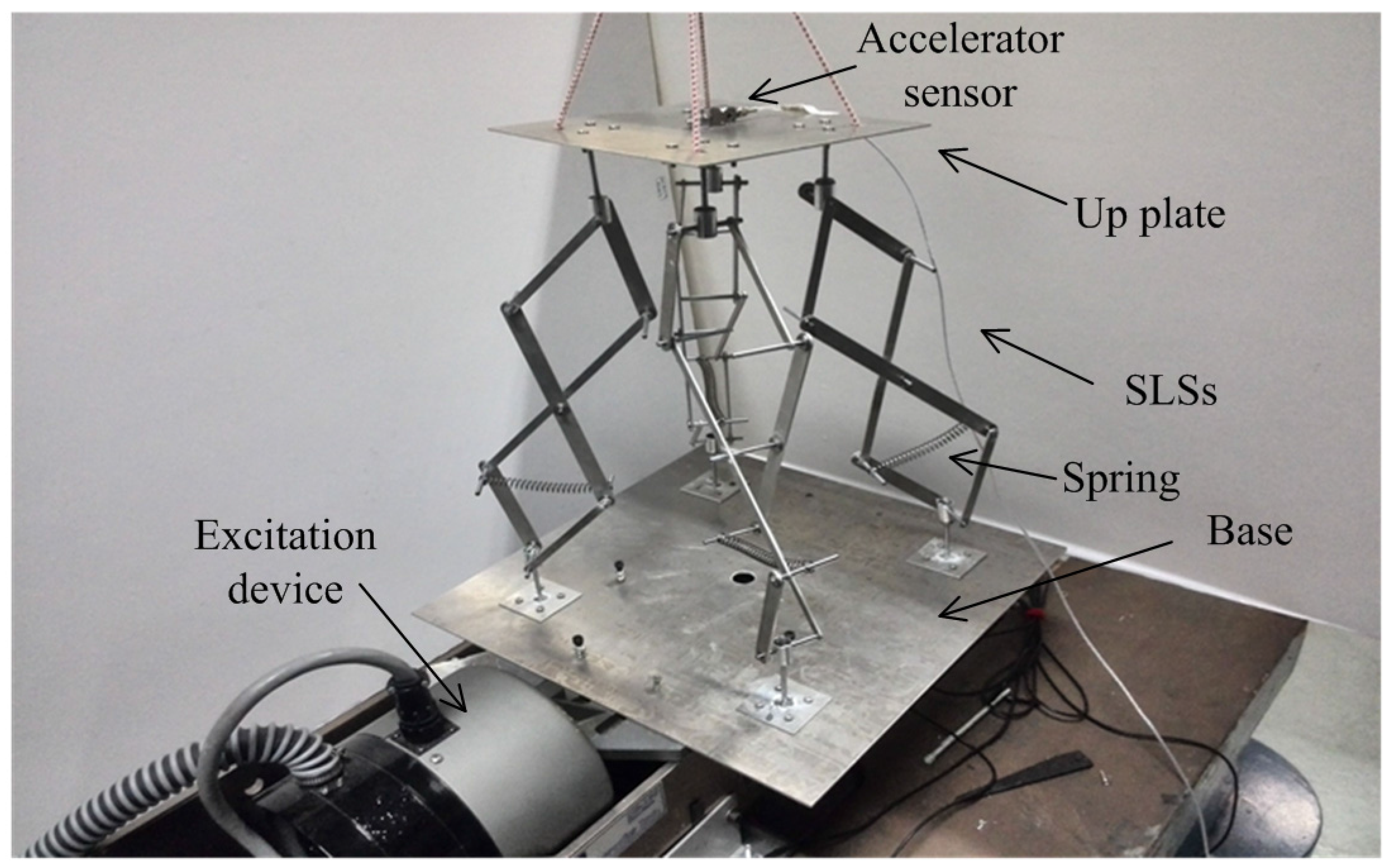
Figure 1 is the experimental prototype of the proposed MDOF isolation system with SLSs. As shown in Figure 1, the up plate of the isolation platform is connected with the base by four scissor-like structures (SLSs). The SLS consists of several connecting rods and a linear spring is assembled in one layer in each SLS.
2.2. Structural Diagram
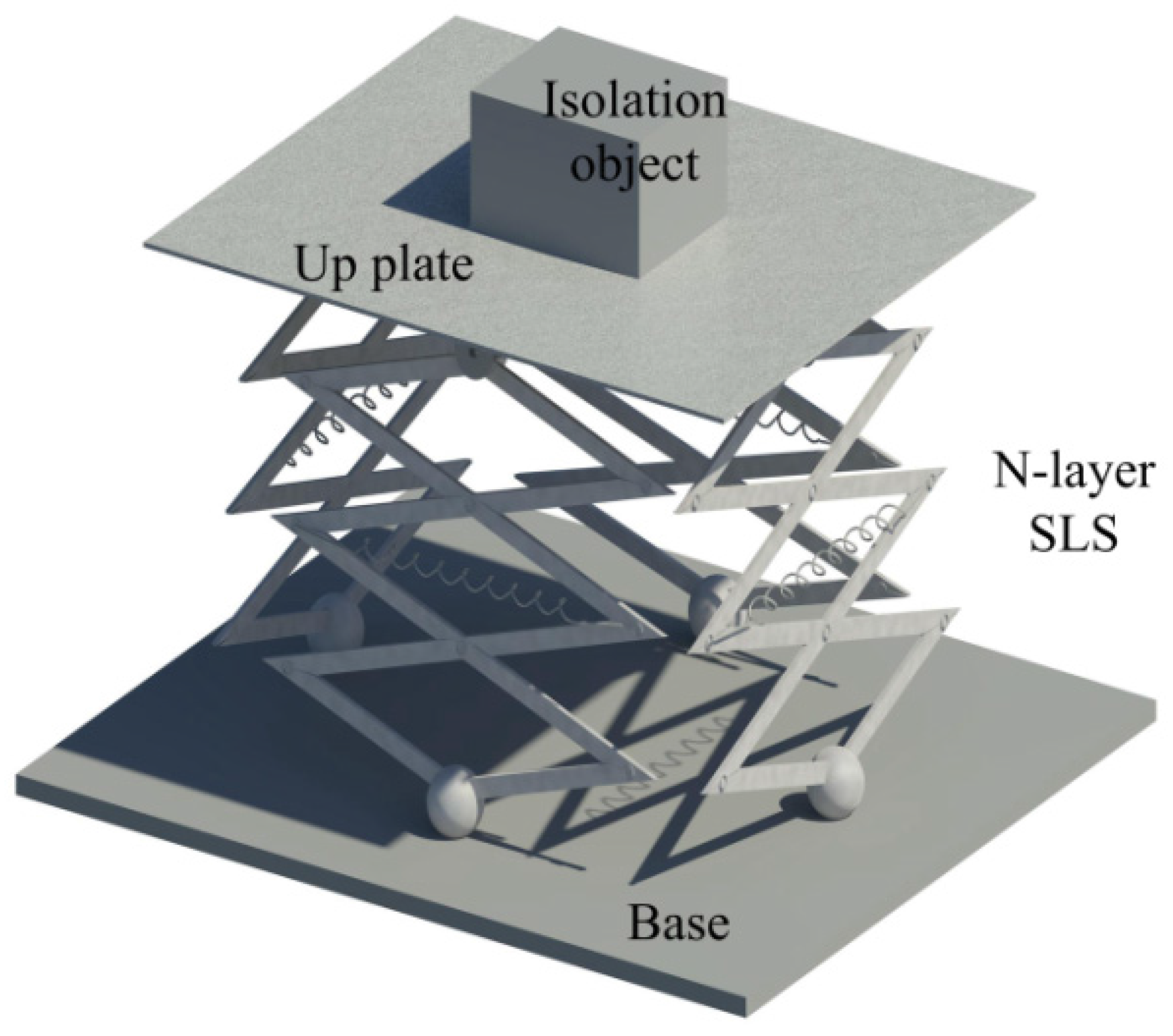
Figure 2 is the structural diagram of the isolation system. Considering the isolation platform is proposed for protecting an instrument (the isolation object) which is put in an arbitrary position on the up plate, the location of the isolation object and the connecting point of the SLS are shown in Figure 3.
In Figure 3, point (c) is the geometrical and mass center of the up plate M1 and point (m) is the center of isolation object with mass M2. The vector the origin of the up plate (c) and the isolation object (m) is as = {L1, L2, L3}. The absolute motions of the platform x = {x, y, z, φx, φy, φz} are chosen as generalized coordinates.
2.3. Modeling
Lagrange principle is used to obtain the model of the isolation platform. The mass of the connecting rods and joints in SLSs are neglected because their weights are much smaller compared to the up plate, base, and isolation object. The kinetic energy consists of the up plate and the isolation object M2, which are set as T1 and T2. The velocity of the up plate is the velocity at the center (c); thus, the kinetic energy T1 is:
For the isolation object M2 whose center has a distance from the center of the up plate, its velocity contains the translational velocity around point (c) and the rotational velocity around the center point (m). Figure 4 is the motions of the isolation object M2 which represents the isolation object (e.g., precise instruments etc.).
Figure 4 is the motion of the isolation object M2 on the up plate whose moments of inertia in different rotational directions are defined as Jxxm, Jyym, and Jzzm. Figure 5 is the deflection of one of the SLSs in the isolator. From Figure 4, the kinetic energy T2 of the isolation object is:
Therefore, the kinetic energy T of the system is:
The potential energy V of the system is from the deformation of the springs in the SLSs. The deflections of the SLSs in the system are shown in Figure 5. The points connected by the SLSs in the base are defined as A0, B0, and C0; the points in the up plate are defined as A1, B1, and C1; and the points in the up plate for deflections are defined as A′1, B′1, and C′1.
Figure 5 shows the deflections of the MDOF vibration isolation system and each SLS. From Figure 5a, it can be seen that the points A0, B0, C0, and D0 make a quadrilateral, and A1, B1, C1, and D1 also make a quadrilateral. From Figure 5b, which is the deflection of the SLS, the original length of the springs in a SLS is 2lcosθ, and the length of the springs can be obtained by . Since the absolute motions of the up plate at the center x = {x, y, z, φx, φy, φz} are chosen as generalized coordinate where x, y, and z are the absolute translational motions and φx, φy, and φz are absolute rotational motions, the location of point A′1, B′1, and C′1 can be obtained by a coordinate transformation matrix. Due to the six-excitation excitations from the base, which are xe = {xe, ye, ze, φxe, φye, φze}, the relative motions of the up plate at the center are = {, , , , , }. The transformation matrices in the three rotational directions are Rx, Ry, and Rz; thus, the rotational transformation matrix is defined as R, which is the dot product of the three transformation matrices.
where Rx, Ry, and Rz are rotational transformation matrices in the φx, φy, and φz directions.
From Figure 5, assuming the coordinate of point (c) is {0, 0, 0}, for the generalization of the results, the vector cA0, cB0, cC0, and cD0 are assumed as cA0 = {xa0, ya0, za0}, cB0 = {xb0, yb0, zb0}, cC0 = {xc0, yc0, zc0}, and cD0 = {xd0, yd0, zd0}, and the vector cA1, cB1, cC1, and cD1 are assumed as cA1 = {xa1, ya1, za1}, cB1 = {xb1, yb1, zb1}, cC1 = {xc1, yc1, zc1}, and cD1 = {xd1, yd1, zd1}. Therefore, the vector A0A′1, B0B′1, C0C′1, and D0D′1 can be obtained by the translational motion matrix and rotational transformation matrix as:
From Equation (5), the deflection of the axis of an SLS is obtained, and then the deformations of springs in an SLS can be obtained by the analysis of the shape of the SLS. Figure 6 shows the deflection of one layer of the SLS.
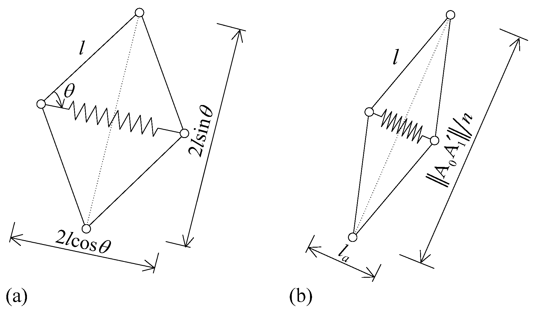
From Figure 6a, it can be seen that the original length of springs in the SLS is 2lcosθ. For deflection, the lengths of the springs in the three SLS are defined as la, lb, lc, and ld, which can be obtained by the triangular relationship shown in Figure 6b which is:
The potential energy V of the system is consisted of the elastic energy of the four springs in SLSs, which can be expressed as:
Considering the air damping of the system, the dynamic equation can be obtained by the Lagrange principle as:
where T is the kinetic energy and V is the potential energy shown as Equations (3) and (7), the mass matrix M of the system is:
After first-order Taylor series expansion, the stiffness matrix K is:
where , and matrix C is the damping matrix of the system:
where ci (i = 1, …, 6) are damping coefficients in the six coordinates.
Due to the assumptions that the amplitudes of motions are sufficiently small, each term in the dynamic equation can be expanded by a Taylor series and higher-order terms can be neglected. Therefore, the dynamic equation of the system is:
where M is the mass matrix, K is the stiffness matrix, and C is the damping matrix, respectively, and x is the motion vector and xe is the base excitation vector. It can be seen that the stiffness coefficients in the stiffness matrix K are dependent on the structural parameters. The parameters θ and n are considered as adjustable parameters for the requirements of different applications.
According to the stiffness matrix K, the linear stiffness equals zero in the φz direction; thus, the minimum natural frequency of the system is zero. Therefore, it defined the value of the frequency where the first resonant peak occurs as the fundamental natural frequency of the proposed system. In this six-direction isolation system, the structural parameters’ stiffness and damping coefficients k and ci are difficult to be changed because the springs and dampers are fixed components, while the structural parameters of SLSs n, θ, and l are easily adjusted. For M1 = 2.75 (kg), M2 = 0.34375 (kg), k = 10,000 (N·m−1), L1 = 0.05 (m), L2 = 0.05 (m), L3 = 0.025 (m), Jxc = Jyc = 0.0573, Jzc = 0.11458, Jxm = Jym = Jzm = 0.0001432, l1 = 0.2 (m), l2 = 0.5 (m), and ci = 2 (N·s·m−1), the values of the natural frequencies of the system for different values of n, θ, and l are shown in Figure 7.
From Figure 7, the fundamental natural frequency of the isolation platform with SLSs can be adjusted by different structural parameters n, θ, and l. It can be seen that the fundamental natural frequency is reduced for increasing n or decreasing θ and l of the SLSs in the isolation platform. As the layer of SLSs increases from one layer to five layers, the fundamental natural frequency reduces from about 70 rad/s to 20 rad/s, as raising the assembly angle of the connecting rods in SLSs from 0.4 to 1.2 rad, the natural frequency increases to about 110 rad/s, and for increasing the length of the rods to 0.4 m, the natural frequency increases to 50 rad/s. Therefore, adjusting the structural parameters of the SLSs in the isolation platform system is effective in reducing the natural frequency, which could improve the isolation effectiveness of the system.
3. Isolation Effect
3.1. Solutions of the System
The isolation effect of the proposed MDOF isolation platform with SLSs reflected by displacement transmissibility is based on the dynamic equation (Equation (12)) and the responses for different structural parameters can be obtained by solving the linearized dynamic equations. When vibration only exits in one direction, the natural frequency in this direction follows , e.g., for ; for ; for . While there are vibrations in all the three directions, the stiffness matrix in Equation (13) reveals that the three-direction vibrations are coupled in linear parts; thus, the anti-frequency band, where the amplitude of response is very small because of the anti-frequency point, occurs and the bandwidth of the bandgap is dependent on the adjustable structural parameters n, θ, and φ. When the excitation is harmonic excitation, such as xei = eicosωt, the responses could be set as xi = aicos(ωt + ϕ). Then, the displacement transmissibility Ti (dB) could be defined as the ratio between the amplitude of the response and the excitation in respective directions as:
where ai is the amplitude of response and ei is the amplitude of the harmonic excitation in different directions. The dynamic equation (Equation (12)) and mass, stiffness, and damping matrices, reveal that the values of the components of the dynamic equations of each degree of freedom can be adjusted by changing the values of the structural parameters n, θ, and l. The isolation effects for different structural parameters are shown in Figure 8.
From Figure 8, it can be seen that, firstly, the natural frequency where has largest peak is reduced by increasing n, or decreasing θ and l, which verifies the analysis of natural frequencies in the previous section. Secondly, the value of the peak is reduced by increasing n and l, while changing θ has no obvious effect on the value of the peak and, thirdly, the response of the amplitudes are lower for larger n and l, or smaller θ. Additionally, it demonstrates that the value of the displacement transmissibility (dB) in the frequency range from zero to the first resonant peak could be controlled to less than zero and the displacement transmissibility is always below zero after the first resonant peak for larger n or l and smaller θ. Therefore, it can be concluded that the isolation effectiveness in a broad frequency band of the proposed isolation platform with SLSs can be improved by adjusting the structural parameters n, θ, and l easily.
3.2. Comparison with a Normal Spring-Mass Isolation Platform
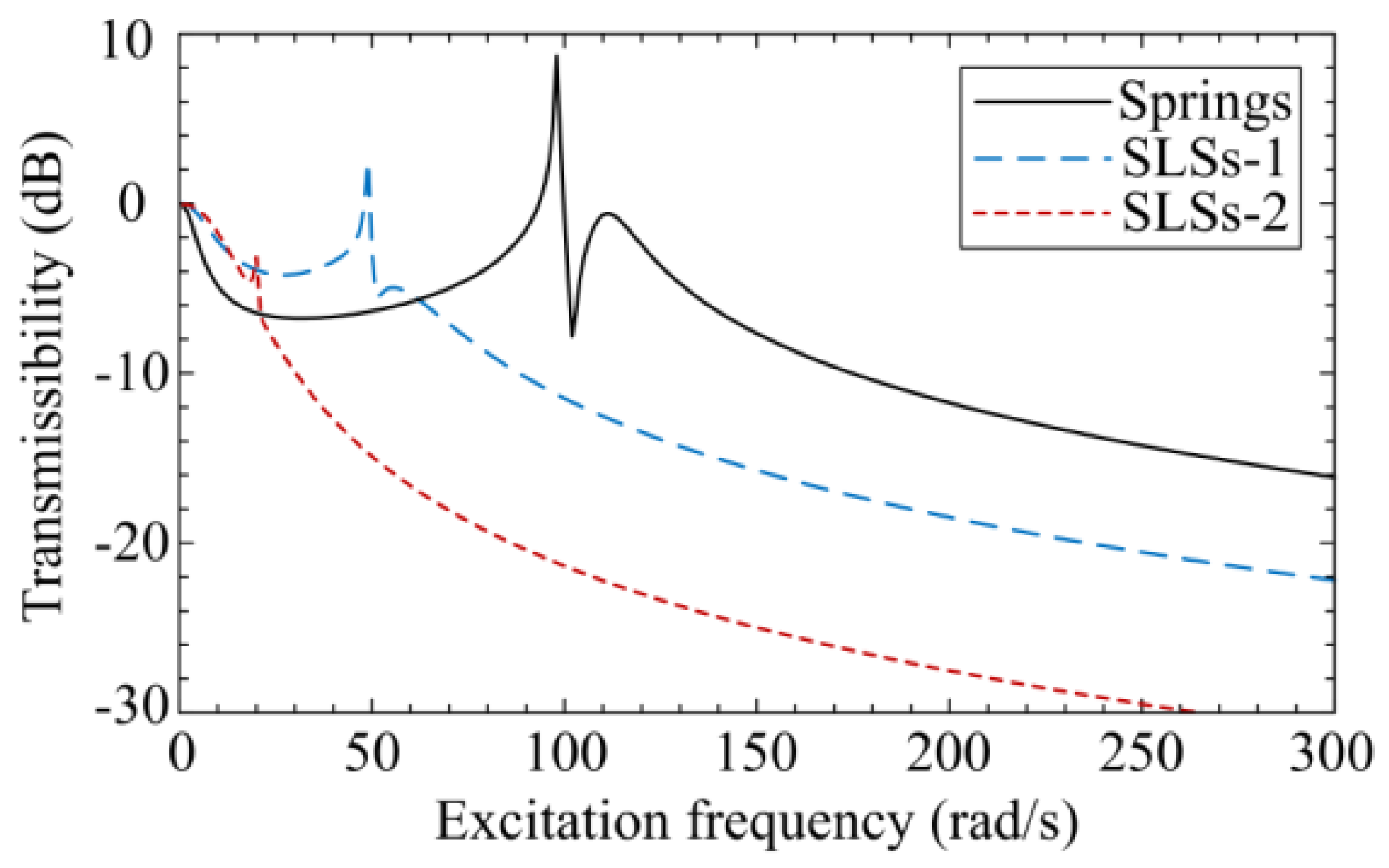
The isolation effectiveness of the isolation platform with SLSs and springs are compared, which is shown in Figure 9. For two cases, n = 2, θ = π/4, l = 0.2 (case 1) and n = 3, θ = π/6, l = 0.2 (case 2), the performances of isolation platform with springs and SLSs are obtained and shown in Figure 9.
From Figure 9, it can be seen that the isolation platform with springs has two obvious resonant peaks are about 100 and 110 rad·s−1 expect zero. While for the two cases of the isolation platform using SLSs, the fundamental natural frequency is much smaller than the one using springs. For case 1 as n = 2, θ = π/4 and l = 0.2, the first resonant peak is at about 50 rad·s−1, and for case 2 as n = 3, θ = π/6 and l = 0.2, the first resonant peak is at 25 rad·s−1. Additionally, the values of displacement transmissibility for the two cases of the platform with SLSs are much smaller than the case with springs in a broad frequency domain.
3.3. Isolation Effectiveness
In order to obtain the natural frequency of the proposed MDOF isolation platform and its isolation effectiveness, random excitation is proposed on the base and the response of the experimental prototype. The frequency domain of the random excitation is from 0 to 100 Hz. The structural parameters of the experimental prototype are n = 2, l = 0.1, l2 = 0.285, l1 = 0.105, M2 = 0.22, M1 = 0, L1 = L2 = L3 = 0, and other structural parameters θ and kl could be adjusted easily for different isolation requirements. In Figure 10, two cases of isolation effectiveness are shown with θ = π/3 and kl = 900.
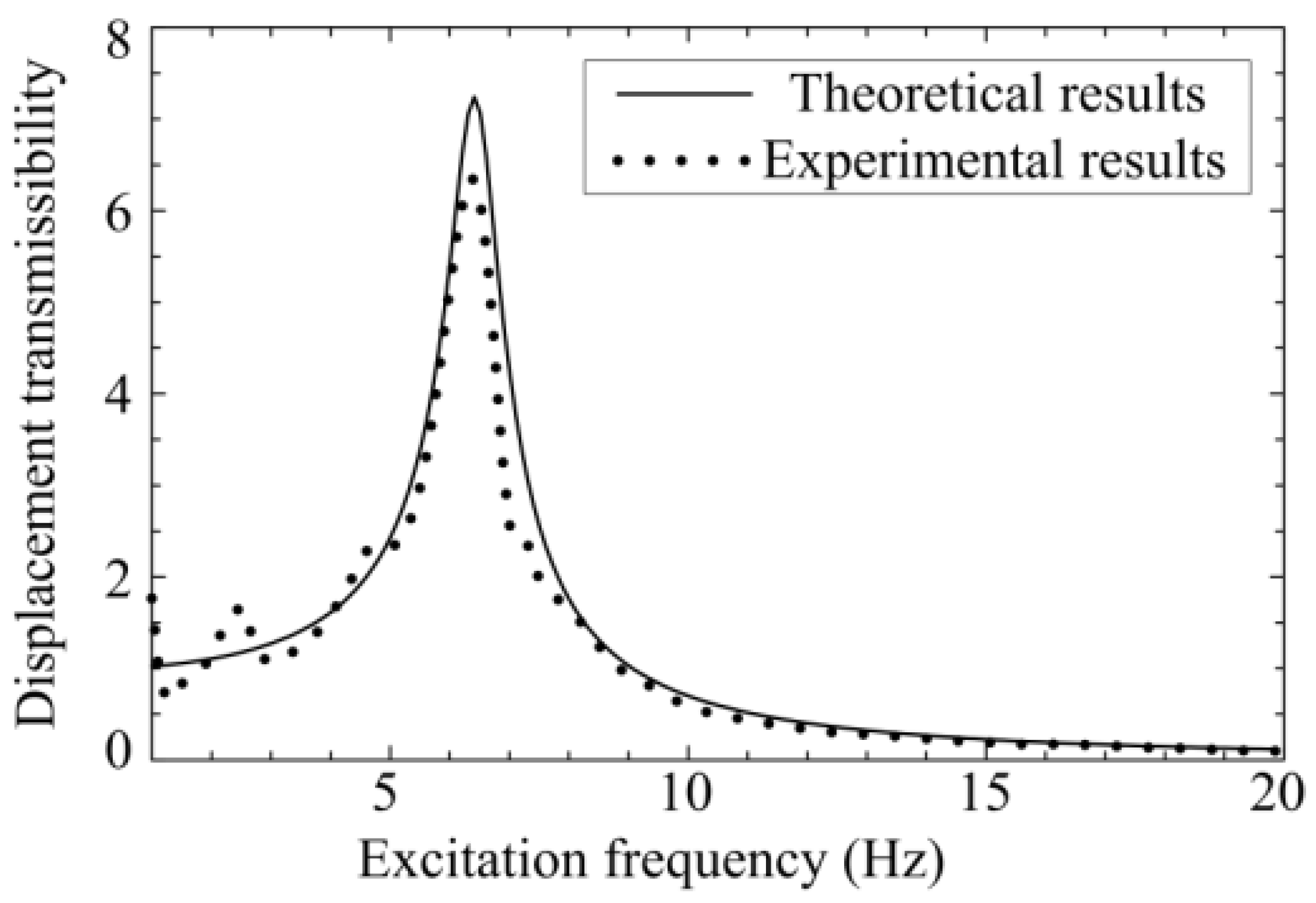
Figure 11 shows the comparison between the theoretical results and experimental results for the periodic excitation with ze = 0.03, xe = ye = φxe = φye = φze = 0, θ = π/3, and kl = 900. The signals of the measured base and the up plate are acceleration signals and the acceleration signals are converted to displacement signals by dividing the square of the frequency since the vibrations are periodic motions.
From Figure 11, the natural frequency of the proposed isolation platform could be reduced by adjusting the structural parameters of the SLSs for different structural parameters. When utilizing four springs with kl = 900 in a normal spring-damping isolator, the vertical-direction natural frequency is as ≈ 20.38 Hz, while for utilizing the SLSs the natural frequency could be reduced to about 6.4, Hz as shown in Figure 11 for θ = π/3, kl = 900. Therefore, using SLSs instead of springs could improve the isolation effectiveness, based on the fact that the natural frequency is reduced and the effective isolation range is increased.
4. Conclusions
This study proposed a MDOF vibration isolation platform with four symmetrical scissor-like structures (SLSs), which is designed for multi-direction isolation applications, especially in microgravity environments, such as protecting instruments and isolation devices in aerospace applications. Theoretical modeling, analysis, and comparison studies demonstrated its advantages and versatility in vibration isolation/control. The advantages of this isolation platform are listed as follows:
- (a)
- By designing the structural parameters of SLSs, the proposed MDOF isolation platform can achieve a lower natural frequency and a much larger effective isolation frequency range compared with normal spring-mass isolators;
- (b)
- Due to the stiffness property with small linear coefficients in different directions of the proposed isolation platform, the system becomes an improved MDOF adjustable isolation platform; and
- (c)
- The adjustable stiffness coefficients in different directions and isolation effectiveness of the isolation platform with SLSs are verified by an experimental prototype and experimental results.
Further studies will focus on the effect of active control for a MDOF vibration isolation system using the scissor-like structures (SLSs) and the combined effect of control parameters and nonlinear coefficients on isolation performance.
Acknowledgments
The authors would like to gratefully acknowledge the support from NSF projects (Ref 11602141) of China.
Author Contributions
Youshuo Song and Xiuting Sun conceived and designed the experiments; Xiuting Sun performed the experiments; Youshuo Song and Xiuting Sun analyzed the data; Xiuting Sun contributed reagents/materials/analysis tools; and Youshuo Song wrote the paper.
Conflicts of Interest
The authors declare no conflict of interest. The founding sponsors had no role in the design of the study; in the collection, analyses, or interpretation of data; in the writing of the manuscript; or in the decision to publish the results.
References
- Lee, Y.Y.; Su, R.K.L.; Ng, C.F.; Hui, C.K. The Effect of Modal Energy Transfer on the Sound Radiation and Vibration of a Curved Panel: Theory and Experiment. J. Sound Vib. 2009, 324, 1003–1015. [Google Scholar] [CrossRef]
- Tusset, A.M.; Balthazar, J.M.; Chavarette, F.R.; Pelix, J.L. On Energy Transfer Phenomena, in a Nonlinear Ideal and Nonideal Essential Vibrating Systems, Coupled to a (MR) MagnetoRheological Damper. Nonlinear Dyn. 2012, 69, 1859–1880. [Google Scholar] [CrossRef]
- Kurt, M.; Eriten, M.; McFarland, D.M.; Bergman, L.A.; Vakakis, A.F. Strongly nonlinear beats in the dynamics of an elastic system with a strong local stiffness nonlinearity: Analysis and identification. J. Sound Vib. 2014, 333, 2054–2072. [Google Scholar] [CrossRef]
- Kurt, M.; Eriten, M.; McFarland, D.M.; Bergman, L.A.; Vakakis, A.F. Frequency–energy plots of steady-state solutions for forced and damped systems, and vibration isolation by nonlinear mode localization. Commun. Nonlinear Sci. Numer. Simul. 2014, 19, 2905–2917. [Google Scholar] [CrossRef]
- Kurt, M.; Slavkin, I.; Eriten, M.; Mcfarland, D.M.; Gendelman, O.V.; Bergman, L.A. Effect of 1:3 resonance on the steady-state dynamics of a forced strongly nonlinear oscillator with a linear light attachment. Arch. Appl. Mech. 2014, 84, 1189–1203. [Google Scholar] [CrossRef]
- Kurt, M. Identification Reduced Order Modeling and Model Updating of Nonlinear Mechanical Systems. Ph.D. Thesis, University of Illinois at Urbana-Champaign, Champaign, IL, USA, 2014. [Google Scholar]
- Zhao, Y.Y.; Xu, J. Effects of delayed feedback control on nonlinear vibration absorber system. J. Sound Vib. 2007, 308, 212–230. [Google Scholar] [CrossRef]
- Jalili, N.; Knowles, D.W., IV. Structural vibration control using an active resonator absorber: Modeling and control implementation. Smart Mater. Struct. 2004, 13, 998–1005. [Google Scholar] [CrossRef]
- Viguie, R.; Kerschen, G. Nonlinear vibration absorber coupled to a nonlinear primary system: A tuning methodology. J. Sound Vib. 2009, 326, 780–793. [Google Scholar] [CrossRef]
- Casciati, F.; Rodellar, J.; Yildirim, U. Active and semi-active control of structures-theory and applications: A review of recent advances. J. Intell. Mater. Syst. Struct. 2012, 23, 1181–1195. [Google Scholar] [CrossRef]
- Zhang, H.; Wang, R.R.; Wang, J.M.; Shi, Y. Robust finite frequency H-infinity static-output-feedback control with application to vibration active control of structural systems. Mechatronics 2014, 24, 354–366. [Google Scholar] [CrossRef]
- Beijen, M.A.; Tjepkema, D.; van Dijk, J. Two-sensor control in active vibration isolation using hard mounts. Control Eng. Pract. 2014, 26, 82–90. [Google Scholar] [CrossRef]
- Liu, J.G.; Li, Y.M.; Zhang, Y.; Cao, Q.; Zuo, B. Dynamics and control of a parallel mechanism for active vibration isolation in space station. Nonlinear Dyn. 2014, 76, 1737–1751. [Google Scholar] [CrossRef]
- Grodsinsky, C.M.; Whorton, M.S. Survey of active vibration isolation systems for microgravity applications. J. Spacecr. Rocket. 2000, 37, 586–596. [Google Scholar] [CrossRef]
- Mehendale, C.S.; Fialho, I.J.; Grigoriadis, K.M. A linear parameter-varying framework for adaptive active microgravity isolation. J. Vib. Control 2009, 15, 773–800. [Google Scholar] [CrossRef]
- Kovacic, I.; Brennan, M.J.; Waters, T.P. A study of a nonlinear vibration isolator with a quasi-zero stiffness characteristic. J. Sound Vib. 2008, 315, 700–711. [Google Scholar] [CrossRef]
- Gatti, G.; Kovacic, I.; Breenan, M.J. On the response of a harmonically excited two degree-of-freedom system consisting of a linear and a nonlinear quasi-zero stiffness oscillator. J. Sound Vib. 2010, 329, 1823–1835. [Google Scholar] [CrossRef]
- Xu, D.L.; Zhang, Y.Y.; Zhou, J.X.; Lou, J.J. On the analytical and experimental assessment of the performance of a quasi-zero-stiffness isolator. J. Vib. Control 2014, 20, 2314–2325. [Google Scholar] [CrossRef]
- Carrella, A.; Brennan, M.J.; Waters, T.P.; Lopes, V., Jr. Force and displacement transmissibility of a nonlinear isolator with high-static-low-dynamic-stiffness. Int. J. Mech. Sci. 2012, 55, 22–29. [Google Scholar] [CrossRef]
- Zhou, J.X.; Xu, D.L.; Bishop, S. A torsion quasi-zero stiffness vibration isolator. J. Sound Vib. 2015, 338, 121–133. [Google Scholar] [CrossRef]
- Shaw, A.D.; Neild, S.A.; Wagg, D.J. Dynamic analysis of high static low dynamic stiffness vibration isolation mounts. J. Sound Vib. 2013, 332, 1437–1455. [Google Scholar] [CrossRef]
- Carrella, A.; Friswell, M.I.; Zotov, A.; Ewins, D.J.; Tichonov, A. Using nonlinear springs to reduce the whirling of a rotating shaft. Mech. Syst. Signal Process. 2009, 23, 2228–2235. [Google Scholar] [CrossRef]
- Liu, X.T.; Huang, X.C.; Hua, H.X. On the characteristics of a quasi-zero stiffness isolator using Euler buckled beam as negative stiffness corrector. J. Sound Vib. 2013, 332, 3359–3376. [Google Scholar] [CrossRef]
- Hao, Z.F.; Cao, Q.J. The isolation characteristics of an archetypal dynamical model with stable-quasi- zero-stiffness. J. Sound Vib. 2015, 340, 61–79. [Google Scholar] [CrossRef]
- Hoque, M.E.; Mizuno, T.; Ishino, Y.; Takasaki, M. A three-axis vibration isolation system using modified zero-power controller with parallel mechanism technique. Mechatronics 2011, 21, 1055–1062. [Google Scholar] [CrossRef]
- Hoque, M.E.; Mizuno, T.; Ishino, Y.; Takasaki, M. A six-axis hybrid vibration isolation system using active zero-power control supported by passive support mechanism. J. Sound Vib. 2010, 329, 3417–3430. [Google Scholar] [CrossRef]
- Kerber, F.; Hurlebaus, S.; Beadle, B.M.; Stobener, U. Control concepts for an active vibration isolation system. Mech. Syst. Signal Process. 2007, 21, 3042–3059. [Google Scholar] [CrossRef]
- Li, B.; Zhao, W.; Deng, Z.Q. Modeling and analysis of a multi-dimensional vibration isolator based on the parallel mechanism. J. Manuf. Syst. 2012, 31, 50–58. [Google Scholar] [CrossRef]
- Preumont, A.; Horodinca, M.; Romanescu, I.; de Marneffe, B.; Avraam, M.; Deraemaeker, A.; Bossensb, F.; Abu Hanieh, A. A six-axis single-stage active vibration isolator based on Stewart platform. J. Sound Vib. 2007, 300, 644–661. [Google Scholar] [CrossRef]
- Darus, I.Z.M.; Tokhi, M.O. Soft computing-based active vibration control of a flexible structure. Eng. Appl. Artif. Intell. 2005, 28, 93–114. [Google Scholar] [CrossRef]
- Yun, Y.; Li, Y.M. A general dynamics and control model of a class of multi-DOF manipulators for active vibration control. Mech. Mach. Theory 2011, 46, 1549–1574. [Google Scholar] [CrossRef]
- Ibrahim, R.A. Recent advances in nonlinear passive vibration isolators. J. Sound Vib. 2008, 314, 371–452. [Google Scholar] [CrossRef]
- Nayfeh, A.H.; Mook, D.T. Nonlinear Oscillations; Wiley-Interscience: New York, NY, USA, 1979. [Google Scholar]
Figure 1.
Experimental prototype of the MDOF isolation system with SLSs.

Figure 2.
The structural diagram of the MDOF isolation system.

Figure 3.
Geometry of the up plate and the isolation object M2 and the coordinates.
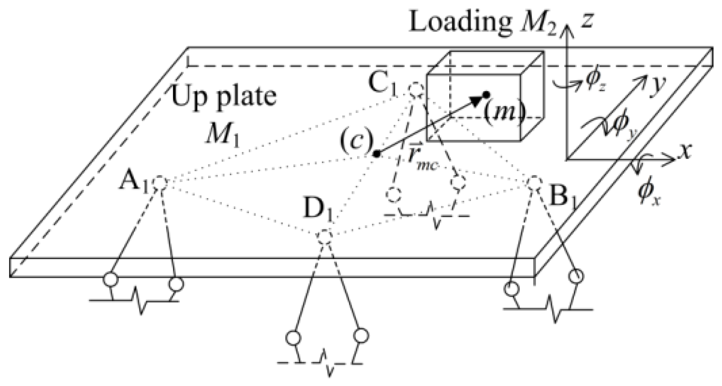
Figure 4.
The motion of the object M2 on the up plate.
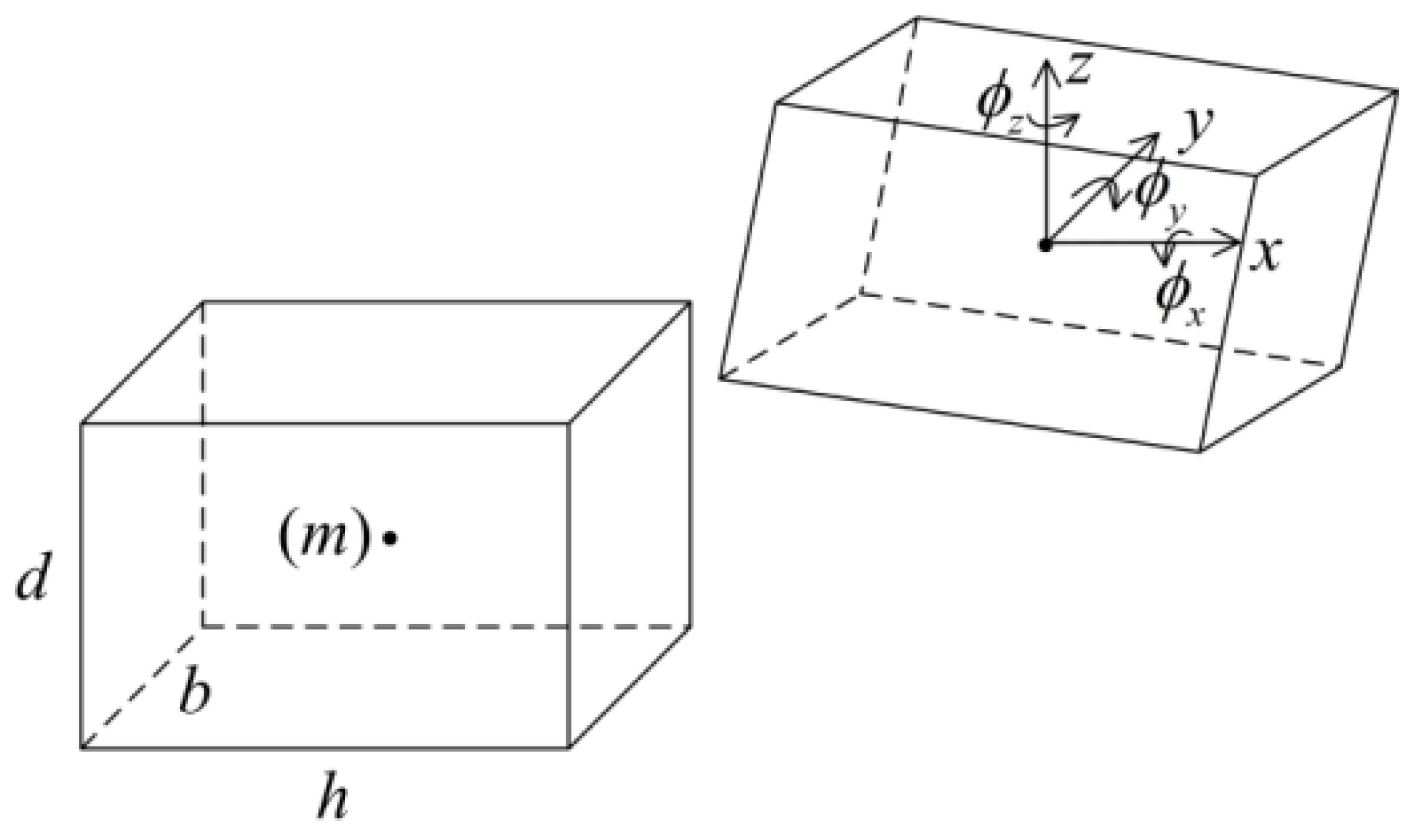
Figure 5.
Deflection of the isolation system: (a) is the location of the up plate and SLSs; and (b) is the deflection of one SLS.
Figure 5.
Deflection of the isolation system: (a) is the location of the up plate and SLSs; and (b) is the deflection of one SLS.
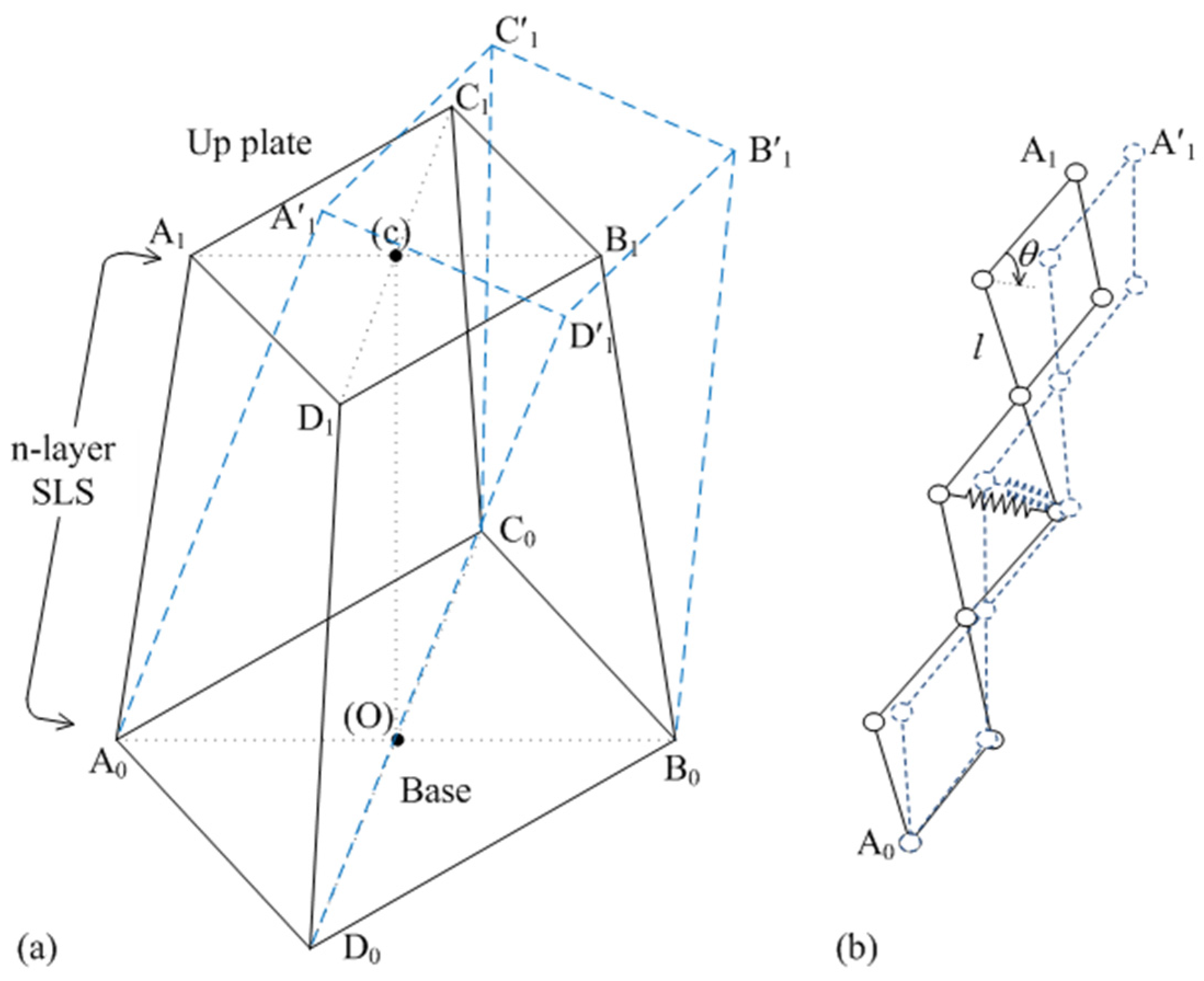
Figure 6.
The deflection of one layer in the SLS: (a) is the original shape; and (b) is the deformed shape.
Figure 6.
The deflection of one layer in the SLS: (a) is the original shape; and (b) is the deformed shape.

Figure 7.
The fundamental natural frequency for different structural parameters: (a) different n when θ = π/4 rad and l = 0.2; (b) different θ when n = 2 and l = 0.2 m; and (c) different l when n = 2 and θ = π/4 rad.
Figure 7.
The fundamental natural frequency for different structural parameters: (a) different n when θ = π/4 rad and l = 0.2; (b) different θ when n = 2 and l = 0.2 m; and (c) different l when n = 2 and θ = π/4 rad.
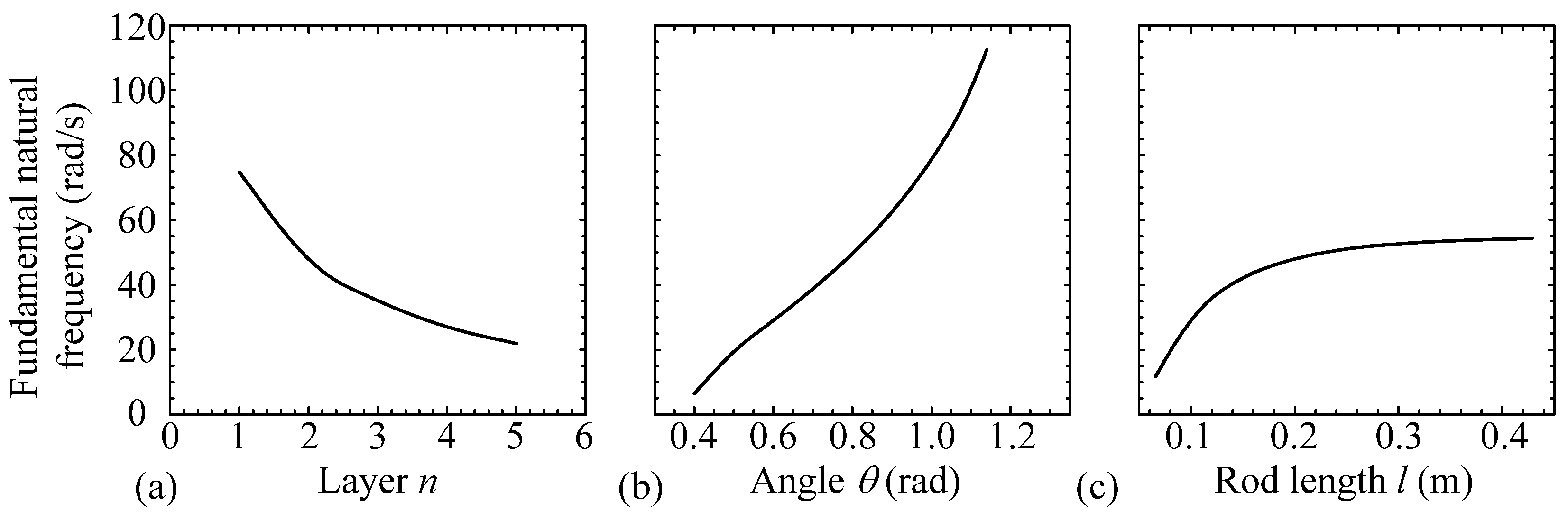
Figure 8.
Isolation effect in the x direction for different structural parameters: (a) different n; (b) different θ; and (c) different l.
Figure 8.
Isolation effect in the x direction for different structural parameters: (a) different n; (b) different θ; and (c) different l.
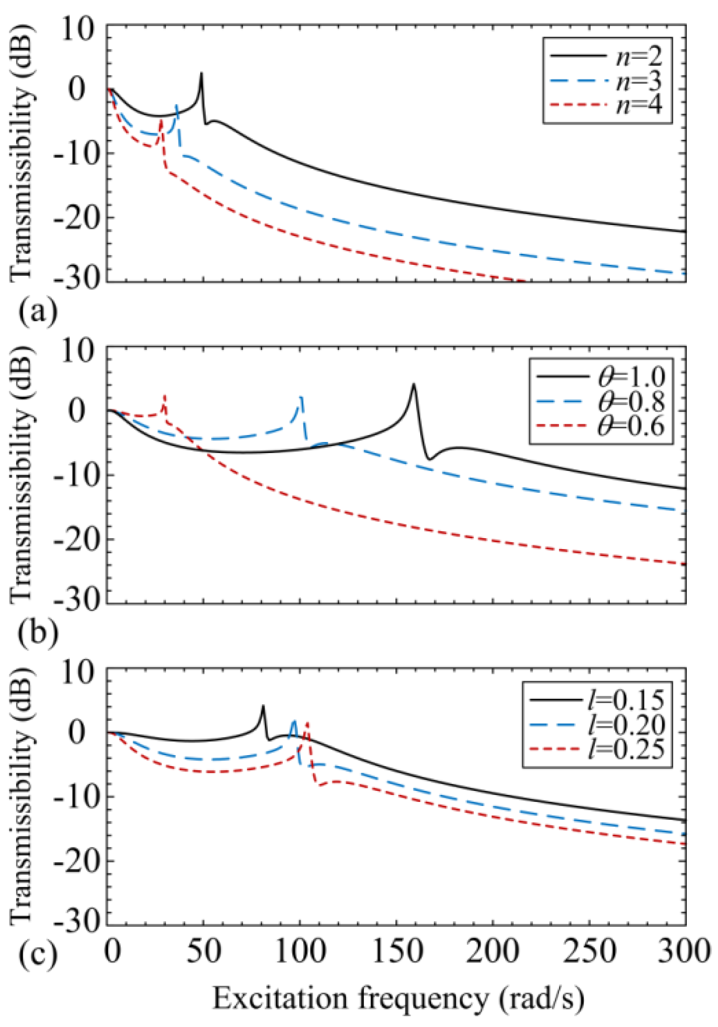
Figure 9.
The comparison of the isolation effectiveness in the x direction between the platform with springs and SLSs for n = 2, θ = π/4, and l = 0.2 (case 1) and n = 3, θ = π/6, and l = 0.2 (case 2).
Figure 9.
The comparison of the isolation effectiveness in the x direction between the platform with springs and SLSs for n = 2, θ = π/4, and l = 0.2 (case 1) and n = 3, θ = π/6, and l = 0.2 (case 2).

Figure 10.
The isolation effectiveness for different structural parameters: (a) for θ = π/3 and kl = 900; (b) θ = 2π/5 and kl = 450.
Figure 10.
The isolation effectiveness for different structural parameters: (a) for θ = π/3 and kl = 900; (b) θ = 2π/5 and kl = 450.
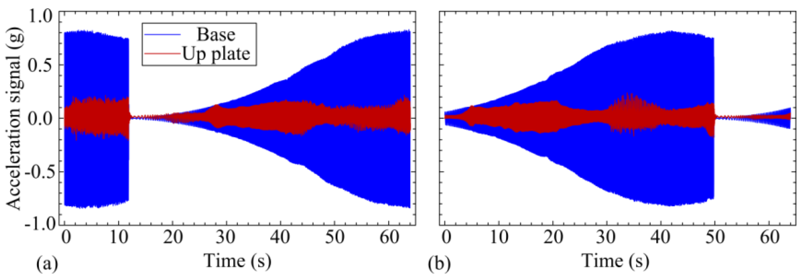
Figure 11.
The displacement transmissibility for vertical direction vibration for θ = π/3, kl = 900 and ze = 0.03.
Figure 11.
The displacement transmissibility for vertical direction vibration for θ = π/3, kl = 900 and ze = 0.03.
© 2017 by the authors. Licensee MDPI, Basel, Switzerland. This article is an open access article distributed under the terms and conditions of the Creative Commons Attribution (CC BY) license (http://creativecommons.org/licenses/by/4.0/).
Share and Cite
MDPI and ACS Style
Song, Y.; Sun, X. Modeling and Dynamics of a MDOF Isolation System. Appl. Sci. 2017, 7, 393. https://doi.org/10.3390/app7040393
AMA Style
Song Y, Sun X. Modeling and Dynamics of a MDOF Isolation System. Applied Sciences. 2017; 7(4):393. https://doi.org/10.3390/app7040393
Chicago/Turabian StyleSong, Youshuo, and Xiuting Sun. 2017. "Modeling and Dynamics of a MDOF Isolation System" Applied Sciences 7, no. 4: 393. https://doi.org/10.3390/app7040393
Note that from the first issue of 2016, this journal uses article numbers instead of page numbers. See further details here.