
Zero-Voltage Ride-Through Capability of Single-Phase Grid-Connected Photovoltaic Systems


1
Department of Electrical Engineering, School of Automation, Northwestern Polytechnical University, Xi’an 710072, China
2
Department of Energy Technology, Aalborg University, Aalborg 9220, Denmark
*
Author to whom correspondence should be addressed.
Appl. Sci. 2017, 7(4), 315; https://doi.org/10.3390/app7040315
Submission received: 10 December 2016
/
Revised: 13 March 2017
/
Accepted: 20 March 2017
/
Published: 24 March 2017
(This article belongs to the Special Issue Advancing Grid-Connected Renewable Generation Systems)
Abstract
:Distributed renewable energy systems play an increasing role in today’s energy paradigm. Thus, intensive research activities have been centered on improving the performance of renewable energy systems, including photovoltaic (PV) systems, which should be of multiple-functionality. That is, the PV systems should be more intelligent in the consideration of grid stability, reliability, and fault protection. Therefore, in this paper, the performance of single-phase grid-connected PV systems under an extreme grid fault (i.e., when the grid voltage dips to zero) is explored. It has been revealed that combining a fast and accurate synchronization mechanism with appropriate control strategies for the zero-voltage ride-through (ZVRT) operation is mandatory. Accordingly, the representative synchronization techniques (i.e., the phase-locked loop (PLL) methods) in the ZVRT operation are compared in terms of detection precision and dynamic response. It shows that the second-order generalized integrator (SOGI-PLL) is a promising solution for single-phase systems in the case of fault ride-through. A control strategy by modifying the SOGI-PLL scheme is then introduced to single-phase grid-connected PV systems for ZVRT operation. Simulations are performed to verify the discussions. The results have demonstrated that the proposed method can help single-phase PV systems to temporarily ride through zero-voltage faults with good dynamics.
1. Introduction
Being an important part of the modern energy infrastructure, distributed renewable energy (DRE) systems have been developed at a fast rate. For instance, in recent years, due to the continuous reduction of the photovoltaic (PV) module price and the strong global demand for environment-friendly energy conversion systems, the solar PV markets have been particularly booming. The capacity of solar PV was increased by 25% in 2014 (i.e., approximately 50 GW), bringing the global total to 227 GW. The annual market in 2015 was nearly 10 times the world’s cumulative solar PV capacity of the last decade. In future, the DRE systems satisfy the requirements for the generation closer to the consumption points [1,2,3]. However, with the fast development of distributed renewable power generations, stability and security have been attracting extensive attention [2].
To cope with the challenges due to a high penetration level of PV systems, many research activities have been conducted recently to improve the integration of PV systems. In summary, it is expected that the grid-friendly PV systems should be multiple-functional. That is, for instance, reactive power control, maximum power point tracking (MPPT), fault islanding detection, harmonic compensation, and fault ride-through (FRT) operation are required for PV systems [4,5,6,7,8,9,10,11,12,13,14]. Actually, some PV power systems on today’s market are already able to provide such services. Nevertheless, the PV systems should be more intelligent in consideration of grid stability, reliability, and fault protection at a high penetration level. A direct reflection of the increasing demands for PV systems is that many countries have revised or have been revising the national grid regulations, where the distributed generations are required to provide advanced grid fault-handling functionalities [15,16,17]. According to the requirements, the PV systems should remain connected under grid faults, and also provide reactive power if demanded. This is also referred to as the low-voltage ride-through (LVRT) capability [13,14,15,16,17]. In extreme cases, i.e., the grid voltage dips to zero, and the disconnection from the grid is also not allowed within a predefined short-time interval (e.g., 150 ms) [15,16], known as the zero-voltage ride-through (ZVRT) capability [18,19,20]. Similarly, in zero-voltage conditions, the PV systems should also support the grid recovery by means of reactive current injection.
Although the ZVRT operation can be taken as a special case of LVRT, a more dedicated control strategy should be performed during the FRT operation. Especially in single-phase grid-connected PV systems, when the fault occurs, the systems still inject sinusoidal reactive current to support the grid without grid information. Challenging issues for the ZVRT operation in the single-phase PV system include how to detect the grid voltage sags quickly, how to switch to the ZVRT operation mode with no grid information, and after the fault, how to resynchronize rapidly without triggering the overcurrent protection. As aforementioned, the single-phase grid-connected PV system is required to operate in different modes accurately and rapidly in complicated situations. In order to implement the ZVRT operation, the following should be considered:
- Grid voltage sag detection—grid monitoring and synchronization control strategies with high robustness and fast dynamics;
- Power calculation and power profiles—the power and current references are adjusted fast and accurately in both normal and FRT operation modes.
The grid synchronization is a fundamental task but a crucial technique in the connection of the PV system to the grid. The capability of instantaneous responses of the synchronization technique has a direct impact on the performance of FRT in terms of accuracy and dynamics. Thus, a lot of synchronization techniques can be found in the recent publications, such as the zero-crossing detection method [21,22], the Kalman filter (KF)-based synchronization method [23], and the discrete Fourier transform method [24], and the phase-locked loop (PLL) methods. The synchronization based on PLL techniques is very attractive among the various synchronization methods because of its easy implementation, high robustness and cost-effectiveness [2,25,26,27,28,29].
Moreover, due to harmonic resonances and grid voltage sags caused by the high penetration of the renewable energy system in low-voltage distributed networks, the more advanced and efficient control strategies in single-phase PV systems are desirable in order to ride through the grid faults. The conventional dual-loop control structure in single-phase PV systems could be applied under the grid fault by directly calculating the current references [30]. When the instantaneous power theory is adopted in single-phase PV systems, the single-phase instantaneous active and reactive powers (PQ) theory [31] can be used to independently control the active and reactive power under LVRT as reported in [11,12,13,14]. In addition, the droop control methods could be considered as an alternative for regulating the active and reactive power under the grid fault [32], on condition that the grid is mainly inductive.
Nonetheless, in light of the above, it becomes essential to combine a fast and accurate synchronization mechanism with a dedicated control strategy for the ZVRT operation. Thus, in this paper, the performance of single-phase PV systems under an extreme grid fault (i.e., the grid voltage dips to zero) is explored. First, an overview of the typical control structure of the single-phase PV system is presented. Furthermore, the performance of the commonly-employed and recently developed PLL methods are assessed in terms of accuracy and dynamics. A control strategy is then proposed for the single-phase grid-connected PV system in the case of ZVRT operation. Simulations are performed in order to validate the performance of the proposed control strategy. Results have verified the effectiveness of the proposed method. Finally, concluding remarks are drawn.
2. System Configuration
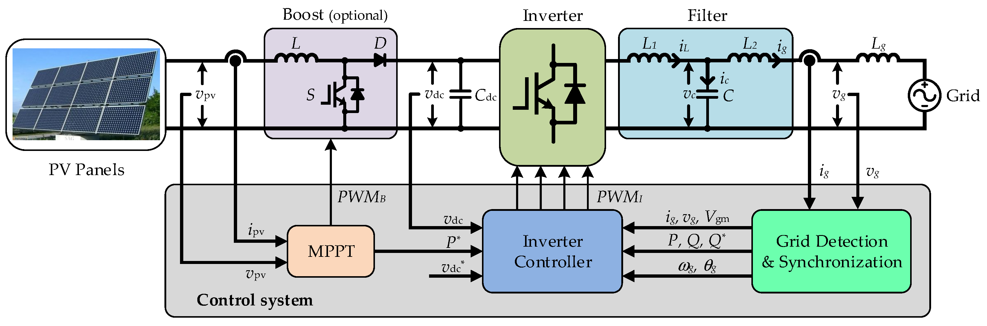
In the low-voltage DRE system, the single-phase configuration is a more competitive solution [11,12,13,14]. A generic control structure of the single-phase grid-connected PV system is shown in Figure 1, with an option of a DC-DC converter, which is used to boost up the PV panel voltage to a suitable level of the following-stage DC-AC converter. The choice of single- or two-stage (i.e., without or with the DC-DC converter) is dependent on the control strategy, efficiency, cost, size and weight, etc. [13,14,30]. To guarantee a high-quality sinusoidal grid current, the inductor–capacitor–inductor (LCL) filter is adopted to improve the switching harmonic with lighter and smaller inductors [33].
In normal conditions, the PV system draws the maximum power from the PV arrays (i.e., in MPPT operation) and transfers it to the grid at unity power factor by using control strategy. The widely employed control strategy in single-phase inverters has two cascaded control loops [3,30]. The inner loop is a current loop, in which the grid current quality can be guaranteed and the overcurrent protection is also ensured. The outer loop is a voltage or power control loop, in which the voltage of the DC-side can be ensured and a reference of the inner current loop is calculated simultaneously in the outer loop.
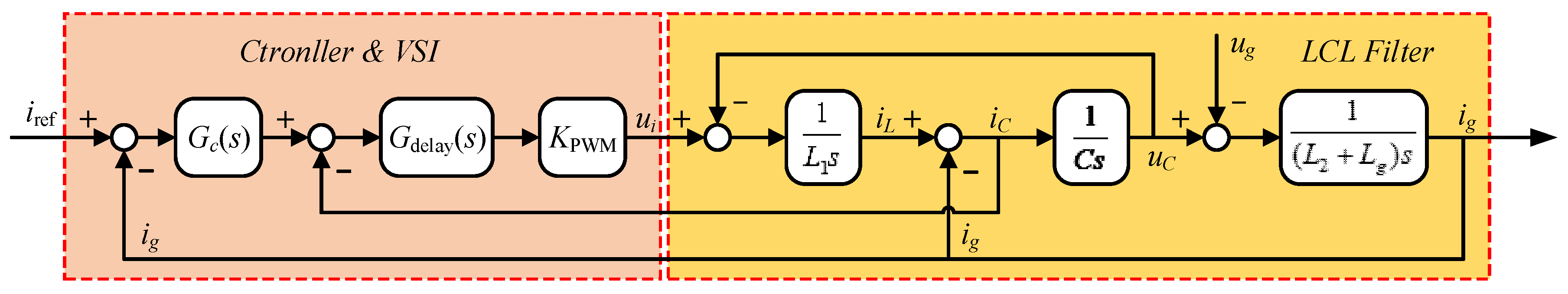
According to Figure 1, the current control loop is responsible for the quality of the injected sinusoidal current, i.e., it needs to satisfy the requirements of the grid code regarding power quality [34]. The control diagram of the current control loop is presented in Figure 2. The capacitor-current-feedback is measured for active damping [35]. The error of the grid-current reference iref and the measured grid-current ig is sent to the current controller Gc(s). For the digital implementation, the time delay should be considered, and Gdelay is used to reflect the total time delay including pulse width modulation (PWM) processing and the delay because of computation [36]. Considering that the switching-frequency is much higher than the fundamental frequency of the grid voltage, KPWM is then the equivalent transfer function of the inverter. As a consequence, the closed-loop current transfer function (i.e., the transfer function for ig and iref) can be derived as
where L1 is the inverter-side inductor, L2 is the grid-side inductor, Lg is the grid impedance, and C is the LCL filter capacitor.
3. Overview of PLL Synchronization Techniques
In the grid-connected PV system, the grid synchronization is very important in the control system, as aforementioned [3,13,21,22,23,24,25,26,27,28,29,30]. A good synchronization can help the system operate at unity power factor in the normal operational mode. Meanwhile, when a grid voltage fault occurs, the PV system should respond immediately by switching to the grid fault operational mode instead of directly shutting down. Therefore, the PLL synchronization techniques should be of fast and accurate dynamics [25,26,27,28,29]. A general structure of a PLL system is shown in Figure 3. It can be divided into three fundamental blocks: (1) Phase Detector (PD); (2) Loop Filter (LF); and (3) Voltage Controlled Oscillator (VCO). Typically, the LF block is represented by a proportional plus integral (PI) controller to improve the PLL filtering capability. The VCO block is represented as an integrator.
The basic PD can be a sinusoidal multiplier. The major drawback of the basic PLL with a sinusoidal multiplier is the output containing double-frequency ripples, which are difficult to be eliminated by the LF, even in an ideal case [3]. Hence, many modified single-phase PLL methods are presented in the literature [3,25,26,27,28,29], where the tasks have been focused on how to advance the PD unit. Each of the PLL methods has its merits in the normal operational mode. However, in response to zero-voltage phase-to-ground faults, the focuses should be shifted towards evaluating the steady-state phase-angle error, dynamics, harmonic rejection and grid fault detection.
The orthogonal signal generator (OSG)-based PD and the modified mixer PD using an adaptive notch filtering (ANF) structure are the desirable solutions, mainly beneficial from their simplicity, robustness and effectiveness [25,26,27,28,29]. Several different structures are established to implement the OSG system or the ANF function. Combined with practical ZVRT operation demands, in addition to the fast dynamics, the capability of grid voltage sag detection is essential. Hence, two representative single-phase PLL methods based on the PD techniques as mentioned above, respectively, will be compared and evaluated.
3.1. Enhanced PLL (EPLL)
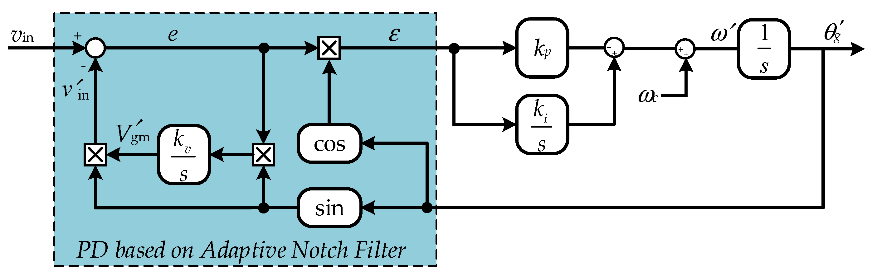
The enhanced PLL (EPLL) improves the performance of the basic PLL structure by employing an ANF-based PD system [3]. A general structure of an EPLL is shown in Figure 4. The control loop achieves phase-angle tracking and amplitude estimating, and the aforementioned major drawbacks of the standard PLL are overcome. Assuming that the input grid voltage vin is a purely sinusoidal waveform at the rated grid frequency, which can be defined as vin = Vgm sin θi, and the output estimated signal can be defined as vout = Vgm′ sin θo′. Therefore, the phase error output of the PD can be expressed as
Meanwhile, in order to estimate the amplitude of the grid voltage, the output signal x can be expressed as
Considering the steady state, the estimated outputs Vgm′, θo′ can then be approximated as Vgm = Vgm′, θi = θo′. Consequently, the double-frequency term approaches zero. The phase angle, frequency, and amplitude of the estimated signals will contain no double-frequency ripples [28].
As aforementioned, compared with the conventional PLL structure, the EPLL can track the major information both in phase and in amplitude with no double-frequency. In order to evaluate the performance of the accuracy and stability of the EPLL, from Figure 4, the transfer functions of the EPLL for amplitude and phase-angle estimations (denoted as GA(s) and Gθ(s), respectively) can be derived as
where kv, kp, and ki are the parameters for adjusting the accuracy and the stability of the EPLL, and , , . The characteristic transfer function shows that the amplitude and phase-angle estimations are a type-II control system. Therefore, the settling time is measured from the start time to the time in which the system stays within 5% of the steady-state errors. The settling time ts can approximately be calculated as
From (4) to (6), it is clear that the control parameters kp and ki mainly affect the convergence rate of the frequency and phase angle. The control parameter kv determines the performance of the amplitude estimation process in the PD. Moreover, in the normal condition, the grid voltage input signal is assumed as an input signal with a unity amplitude, i.e., Vgm = 1. Hence, in the LVRT/ZVRT operations, the response of the EPLL depends on the amplitude estimation of the grid voltage.
3.2. Second-Order Generalized Integrator-Based PLL (SOGI-PLL)
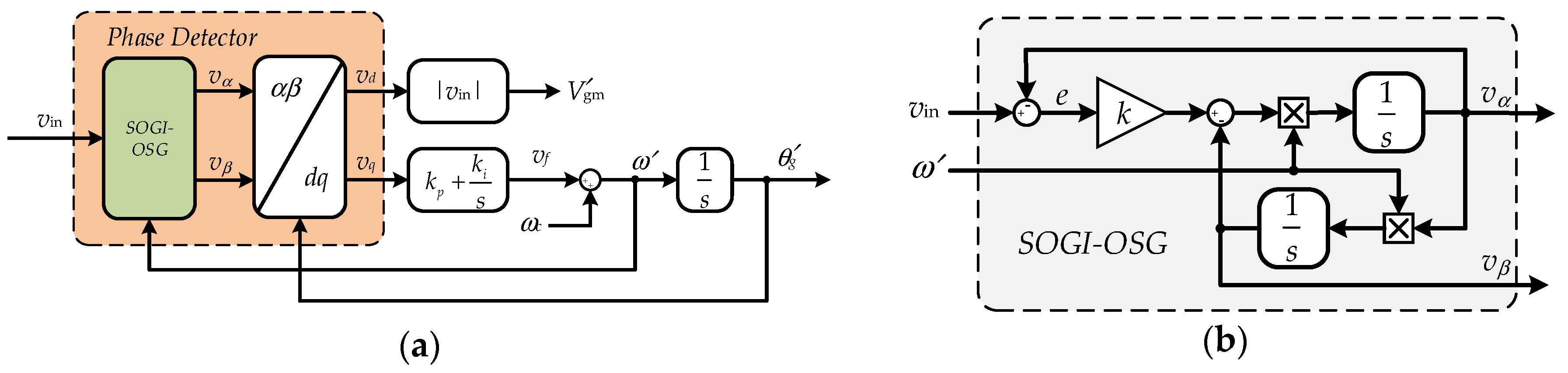
The second-order generalized integrator-based PLL (SOGI-PLL) is an effective approach to implement the OSG-based PD to generate the orthogonal signals, and then the conventional synchronization can be adopted [29]. A general structure of a SOGI-PLL is shown in Figure 5. The quadrature signal generation (QSG) contains a pair of 90°-shifted output signals, vα and vβ, which are generated by a second-order adaptive filter, also known as a sinusoidal integrator (more specific, a second-order generalized integrator (SOGI)). The OSG-based PD unit is followed by Park transformation that gives the dq-voltages, vd and vq. The SOGI-based PD has the advantages of frequency adaptability and harmonic rejection [26,29].
The characteristic transfer function of the adaptive filtering based on the SOGI is given as
in which ω′ is the estimated grid angular frequency. Further analyzing the SOGI-OSG-based PD block in Figure 5, the closed-loop transfer functions can be derived as
where k is the control parameter that can regulate the bandwidth and dynamic response of the estimated output signals. Considering the grid voltage input signal as vin = Vgm cos(ωt + φi), the time domain outputs can be derived as
in which Aα, Aβ, φα,, and φβ are functions of Vgm, φi, and k. From (9), assuming that the instantaneous phase angle is defined as ωt + φi = θi, and the output estimated signal phase angle is defined as θo′, applying the Park transformation yields the signals in the dq-reference frame as [26]
At the steady state, the high-frequency fluctuating terms in (9) and (10) with the time constant of 2/kω will be zero. And thus,
which shows that vd estimates the amplitude of the input grid voltage, and the phase angle detected by the PLL is provided by vq. Furthermore, the error transfer function of the PD based on the SOGI-OSG can be approximated as [25,26,27]
where Vgm′ is the estimated amplitude of the grid voltage, eθ = θi − θo′, and τ = 2/kω. Hence, the transfer functions of the SOGI-PLL for phase angle estimations can be derived as
As aforementioned, the dynamic response of the SOGI-PLL is also affected by the amplitude of the grid voltage. Due to the LVRT/ZVRT operations, the relationship between the settling time and overshoot in the dynamic response should be balanced. For the amplitude detection of the grid voltage, the passband and dynamic response are only dependent on the control parameter k. In order to evaluate the performance of the SOGI-OSG-based PLL, the settling time (5%) can be approximated as
An optimal relationship between the settling time and overshoot is achieved by taking k = 0.707.
3.3. Comparison of the PLLs
According to the aforementioned analysis, the applicability of the selected PLL methods should be identified, which can detect the grid fault precisely and rapidly under grid voltage faults (even drop to zero). The system and control parameters are shown in Table 1. Since a fault case of the grid voltage occurs, the steady-state output signal should maintain at the rated frequency with small or no fluctuation and overshoot. Therefore, the comparison will be focused on the speed and precision of detecting the grid voltage, frequency and phase by the selected PLL systems.
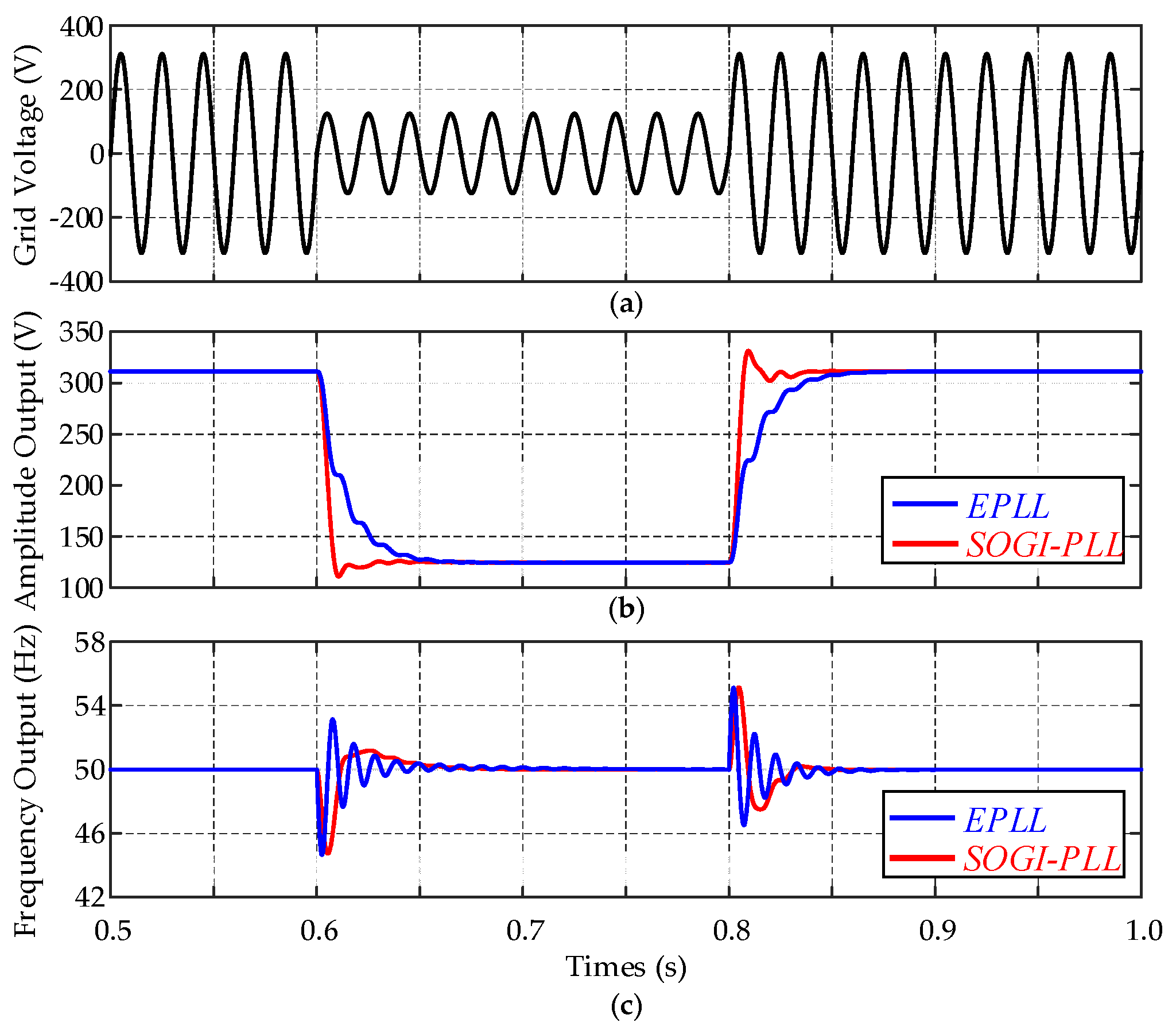
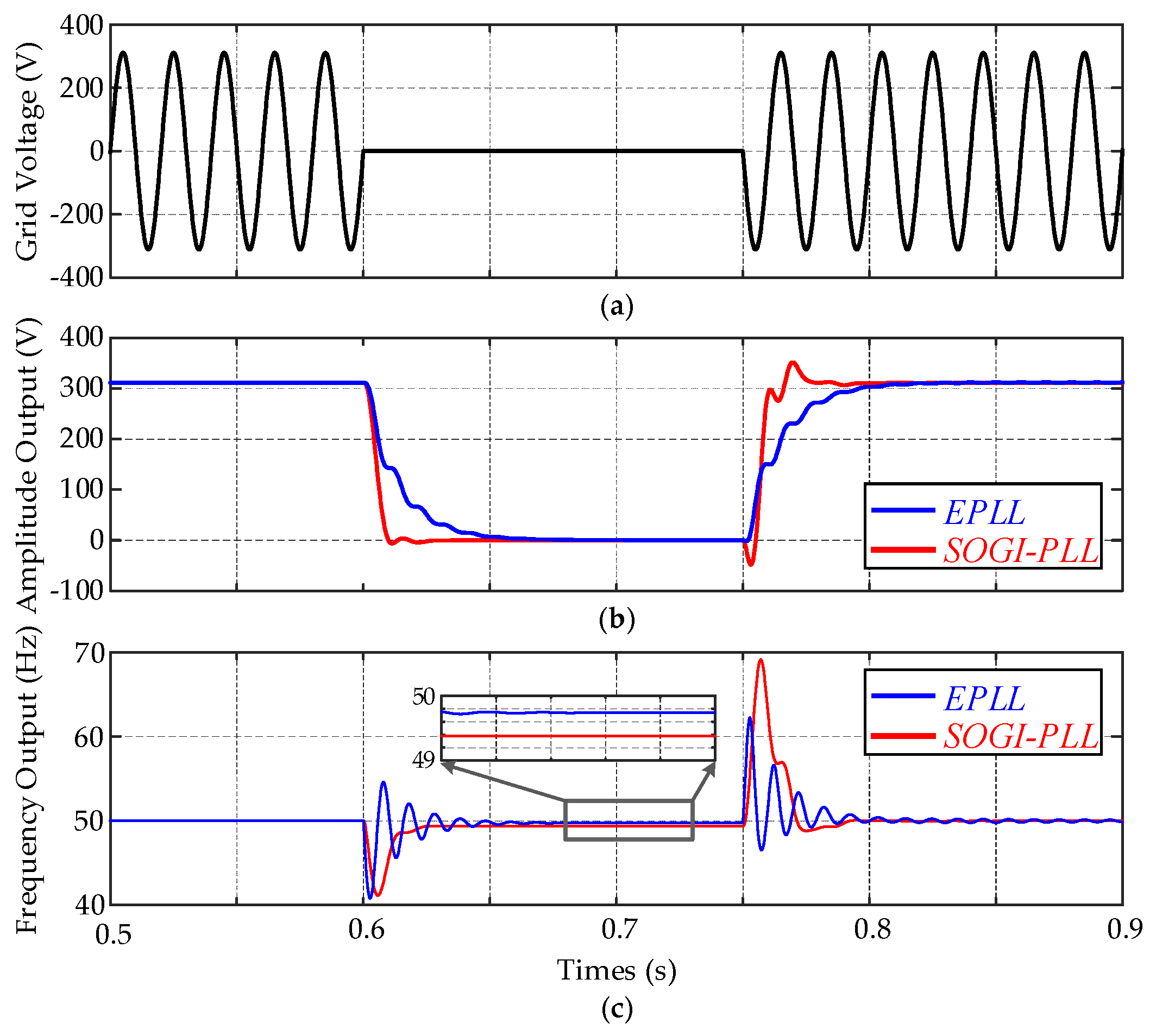
Figure 6 shows the dynamics of the PLLs under a grid voltage drop of 0.6 p.u. Both methods can estimate the amplitude and the frequency of the grid voltage without double-frequency ripples in the steady-state condition, as shown in Figure 6. When comparing with the EPLL, the SOGI-PLL approaches the steady state faster. However, the overshoot of the SOGI-PLL is observed in the progress of the amplitude detection. Figure 7 then shows the dynamics of the PLLs under a voltage sag of 100% (i.e., the grid voltage drops to zero). Compared with the LVRT condition, the superior performance of the SOGI-PLL is significant, as seen from Figure 7. However, the EPLL takes the advantage in suppressing the overshoot. Moreover, it should be noted that the estimated frequency outputs have steady-state errors in both the SOGI-PLL and EPLL when the grid voltage drops. It will affect the accuracy of the phase and frequency detection in the ZVRT operation.
A comparative analysis of the EPLL and SOGI-PLL reveals that both of them can estimate the amplitude and filter out the harmonics, resulting in clean signals for synchronization. However, the output signals of the EPLL present large variations during transients, and the output signals of the SOGI-PLL present large overshoots. Compared with the EPLL, the SOGI-PLL approaches the steady state much faster, and that is more effective depending on the voltage sag depth. Thus, in general, the SOGI-PLL system can be a promising solution for a monitoring and synchronization technique used in single-phase applications, especially in the case of LVRT/ZVRT operations. However, the steady-state error in the case of zero-voltage faults is also observed.
4. Control Strategy in Zero-Voltage Ride-Through Operation
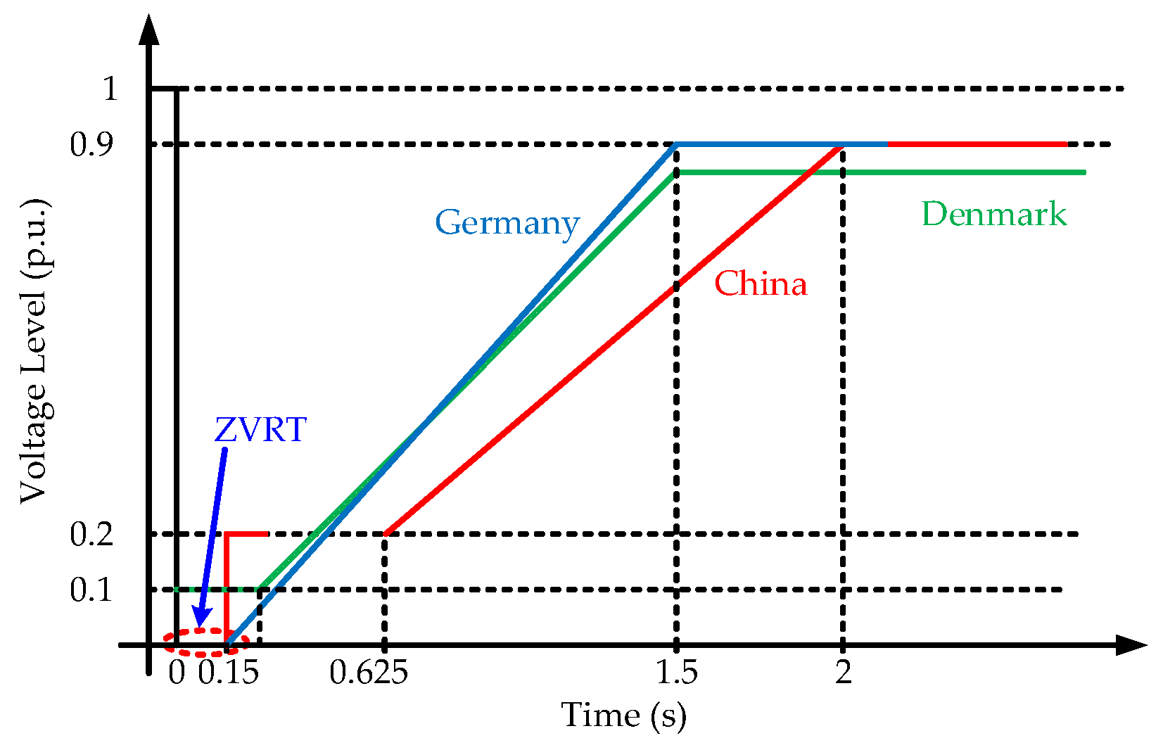
Once the grid phase-to-ground fault is detected by the grid synchronization, the photovoltaic (PV) system should switch to the grid fault operational mode with reactive power injection to support the grid recovery. In different countries, to fulfill various local conditions under national realities, the suitable grid code has been proposed [15,16,17]. Figure 8 exemplifies the voltage profiles for the possible fault condition in some countries, where the PV systems should operate under the specific condition when the grid voltage is above the curves [15,16,17].
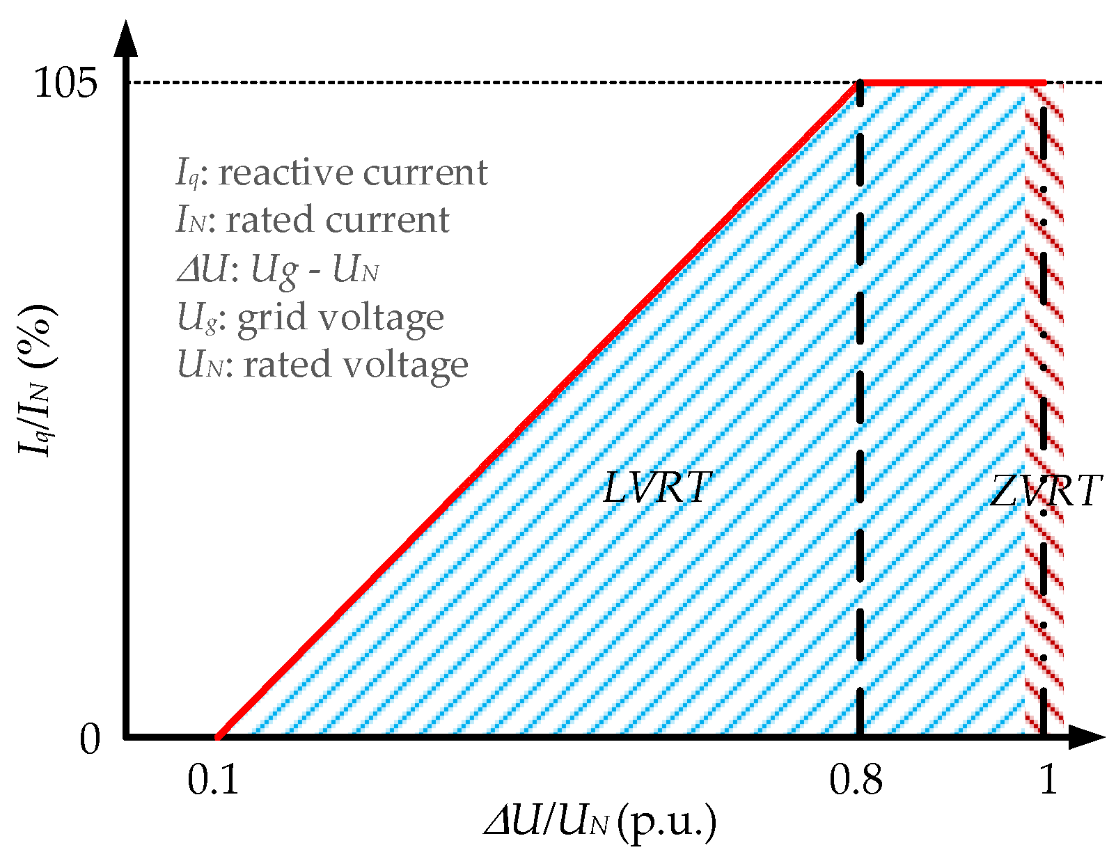
According to the requirements in Figure 8, it is clear that different from the anti-islanding protection, the ZVRT requires that in a short-time interval (e.g., 150 ms) even with a grid voltage amplitude of 0 V in Germany and China [15,16], the system should remain connected. Thus, in order to support the grid recovery, the controller should provide additional functionality to adjust the current reference for reactive power injection. The reactive current injection profile in China is presented in Figure 9 [16]. As it is shown in Figure 9, the required reactive current Iq to support the grid voltage in the Chinese grid regulations is defined. The characteristic in the grid code is the injected reactive current increased with the depth of the grid voltage sag (i.e., the fault severity). At certain critical points, it should inject one p.u. of the reactive current. The required reactive current Iq in the Chinese grid code can be given as [16]
where UN and IN are the nominal grid voltage and the nominal inverter current, ΔU is the depth of grid voltage sag, and Iq is the required injected reactive current when the fault occurs.
As in the above discussions, it is known that the current reference should be properly generated under grid faults. Hence, the conventional dual-loop control structure for single-phase PV systems can be applied, where the current references can be directly calculated. The control diagram of the single-phase dual-loop control structure is shown in Figure 10. Based on the single-phase instantaneous power control theory, the current reference of the inner control loop can be obtained through the active power and reactive power references (i.e., P* and Q*), as shown in Figure 10. As aforementioned, the reactive current injection is dependent on the voltage sag depth. It is calculated considering the amplitude detection of the PLL system.
According to the single-phase PQ theory [13,14,31,34], the active and reactive power can be controlled independently in the outer power control loop, and then the grid current references are generated, being a dual-loop control structure [30]. In order to regulate the power reference, an OSG system is needed to generate the quadrature components, vα and vβ. The grid current references are given by
where iα* is the grid current reference ig*, vgα, vgβ, igα, and igβ are the orthogonal components in the αβ-frame, P* and Q* are the active power and reactive power references, respectively.
For the inner current control loop, a hybrid controller including a proportional resonant (PR) and a harmonic compensator (HC) is selected considering both control complexity and power quality [6,13,14,30]. The PR controller overcomes the most drawbacks of the classical PI controller, which is steady-state error [30]. In addition, the HC controller provides a good capability of harmonics rejection. As a consequence, the hybrid PR with HC controller shows a better performance. The current controller relating PR controller Gc(s) and HC controller Gh(s) can be expressed as
where kp is the proportional gain, ki and kih are the resonant and harmonic compensator gains, h is the harmonic order, and ω0 is the fundamental frequency.
During ZVRT operation, the system loses all the grid information. The PV system should switch to the ZVRT operation mode from the normal condition or the LVRT operation mode, when the grid voltage sags to zero. The injection current from the grid-connected inverter should totally be reactive current in order to support the grid recovery. As the requirement of the grid code, the system must achieve the voltage fault detection, operation mode switch, and reactive current injection as soon as possible. The fast dynamics and accuracy of the grid fault detection are then essential.
However, in the ZVRT operation, the estimated grid voltage is in an undefined and abnormal condition caused by no grid information. As discussed previously, the steady-state error of the PLL estimated frequency output is not zero in the case of ZVRT faults. Therefore, the common implementation of PLL methods does not provide the ride-through ability. A feasible solution is to adjust the parameters of the LF (i.e., kp, ki) to reduce the steady-state error. However, the dynamics will be sacrificed during fault ride-through, making it not very practical. Hence, a novel approach is proposed.
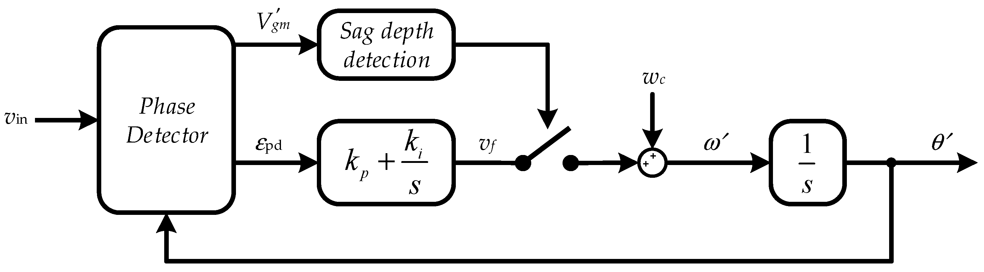
Basically, the idea is that the detected grid voltage controls a switch to change the operational mode of the PLL, as shown in Figure 11. According to the Chinese grid code [16], the system should inject only reactive current in the case of voltage faults (below 0.8 p.u.). Therefore, the voltage sag of 0.8 p.u. can be set as the threshold to change the PLL operational mode. More specifically, when the grid voltage level is above 0.8 p.u., the PLL continuously estimates the grid phase angle, frequency, and amplitude. Once the grid voltage sags (i.e., below 0.8 p.u.), a fixed frequency (i.e., being the nominal grid frequency) is imposed to the VCO, and then the phase angle for the control system is generated, as shown in Figure 11.
5. Performance Evaluation
The performance of the control strategy in ZVRT operation is examined in this section. The SOGI-PLL system is used to detect the fault condition by monitoring the grid voltage frequency and the amplitude [13,14]. The entire system is simulated in MATALB/Simulink. A PV array block in MATLAB/Simulink/Renewables/Solar is used to implement an array of photovoltaic (PV) modules. In normal MPPT operation mode, the active power reference P* is the tracked MPPT output power of the PV panels. In the faulty grid operation mode, the PV panels should reduce its output power when the grid presents a voltage fault. The reduced power level is dependent on the voltage sag depth and the nominal current. The parameters for the system are listed in Table 2. The parameters of the SOGI-PLL are the same as those in Table 1. The results are shown in Figure 12, Figure 13 and Figure 14.
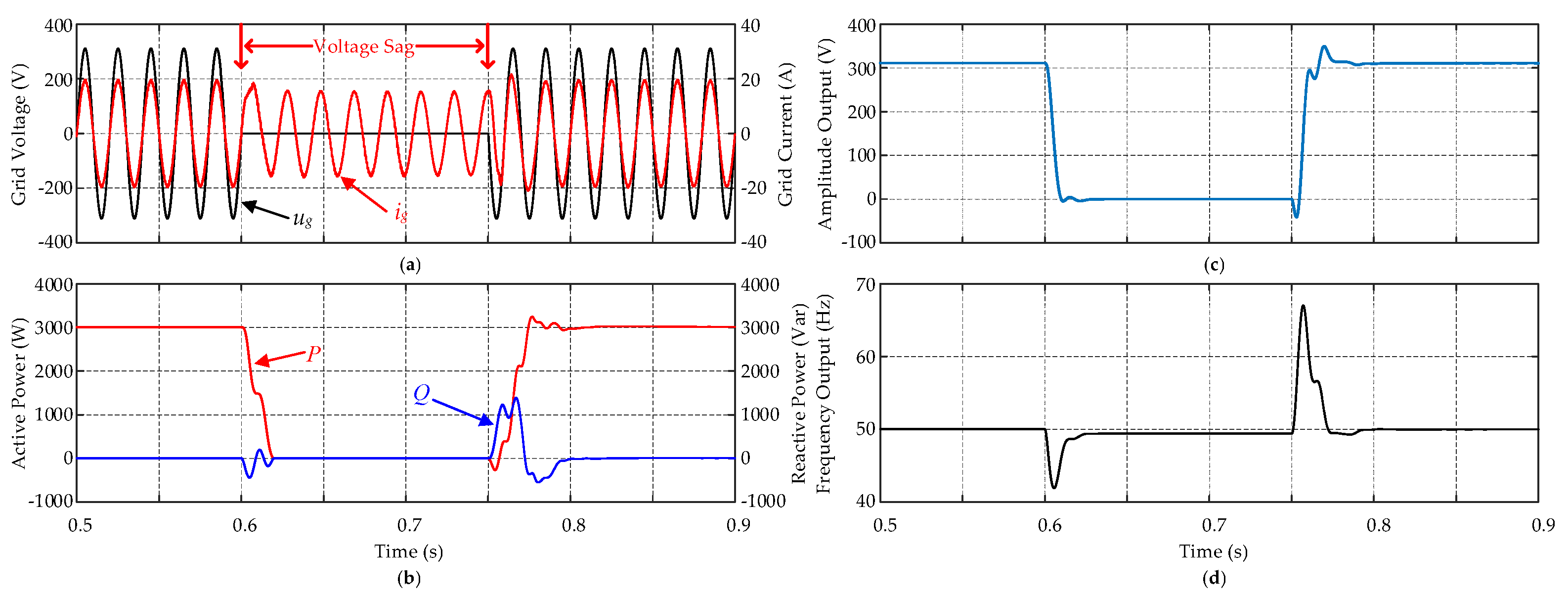
Simulation results in the case of ZVRT operations with the normal SOGI-PLL and the modified PLL based on the SOGI-OSG are shown in Figure 12 and Figure 13. It can be seen that at t = 0.6 s, a phase-to-ground fault occurs (i.e., the grid voltage sags to 0 V). Once the zero-voltage grid fault is detected, the system is controlled to continuously inject currents in order to support the grid recovery. When the grid voltage recovers to normal conditions at t = 0.75 s, both methods guarantee a seamless operation transition to the unity power factor mode. In contrast, the frequency of the injected reactive currents in the ZVRT operation with the normal SOGI-PLL has been observed with small steady-state errors. When the grid voltage recovers, the overshoot of the amplitude and frequency estimation in the ZVRT operation with the normal SOGI-PLL is more obvious. However, in the ZVRT operation with the proposed modified PLL structure, both the steady-state error and the overshoot have been reduced. Furthermore, the recovery response time has been improved slightly.
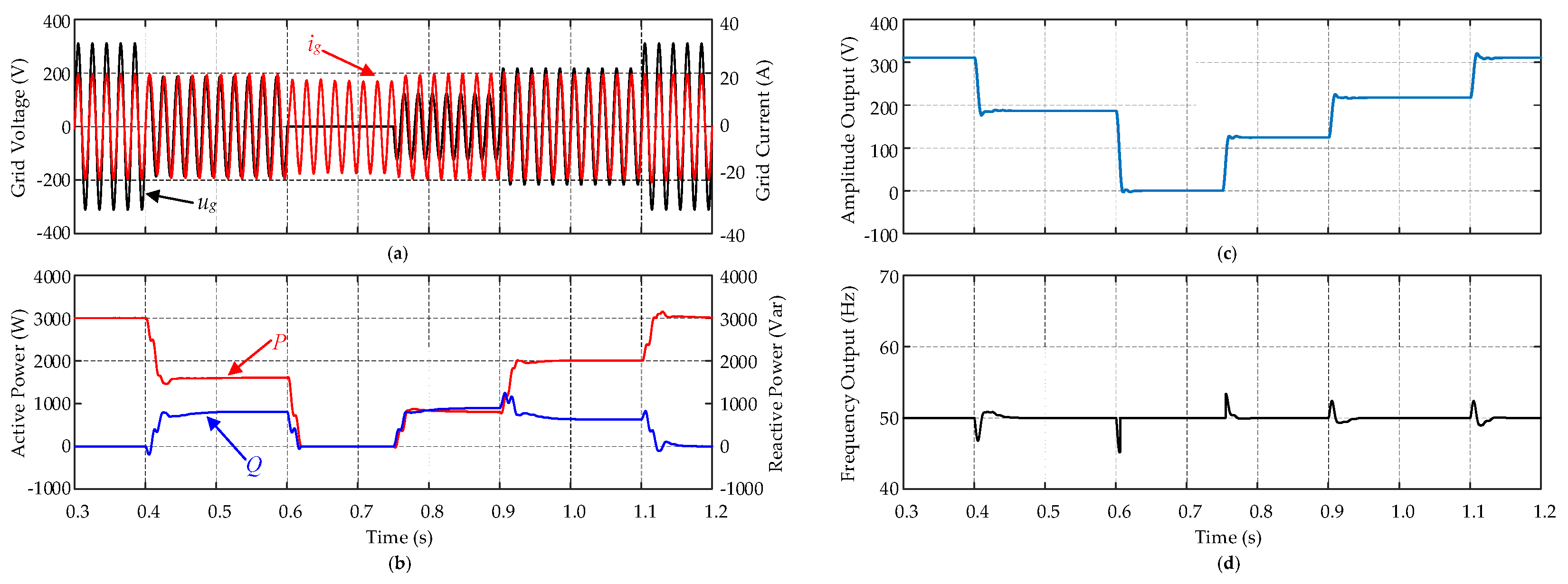
As it is further shown in Figure 14, a recurring grid voltage fault is evaluated. It can be seen in Figure 14 that at t = 0.4 s, a phase-to-ground fault occurs when the grid voltage drops to 0.6 p.u., similar to the case in Figure 13a, and the system switches to the LVRT operation mode to adjust the active and reactive power injection to the grid. When the voltage continues to drop to zero at t = 0.6 s, the system has been switched to the ZVRT operation mode. The active and reactive power are both zero since the grid voltage is zero. However, the reactive current should still be injected for grid support. It is obvious that the power response drops slightly. The overshoots of the estimated amplitude and frequency are small, when the voltage recovers to 0.4 p.u. at t = 0.75 s, as shown in Figure 14c,d. Furthermore, when the voltage continues to recover to 0.7 p.u. at t = 0.9 s, the system increases the active power injection to 70% of its rated power. Until the fault is cleared at t = 1.1 s, the system goes back to the normal operational mode. Compared with the case where the grid voltage directly drops to zero as shown in Figure 12 and Figure 13, the proposed control method guarantees a good dynamic performance under the recurring grid voltage fault.
6. Conclusions
The performance of single-phase grid-connected PV systems in the ZVRT operation has been explored in this paper. Typical techniques of monitoring and synchronization using PLL systems have been compared and analyzed in detail. The selected PLL methods have been compared in terms of accuracy and dynamic response to the ZVRT operation. The benchmarking has revealed that the SOGI-PLL system is a promising solution for monitoring and synchronization in single-phase applications under the LVRT/ZVRT operations. However, the steady-state error during the ZVRT operation should be reduced or eliminated. Then, a control strategy based on the modified SOGI-PLL system has been proposed in this paper for single-phase grid-connected PV systems in the ZVRT operation. The performances of the single-phase grid-connected PV systems in the case of ZVRT operations with the proposed control strategy have been evaluated. Results have validated the effectiveness of the proposal in terms of fast dynamics and accurate responses.
Acknowledgments
The authors would like to thank China Scholarship Council (CSC) for supporting this joint-supervising Ph.D. project in the Department of Energy Technology at Aalborg University, Denmark.
Author Contributions
Z.Z. and Y.Y. conceived and designed the research idea and the framework; Z.Z. performed the simulations; Y.Y., R.M. and F.B. analyzed the data. Z.Z. wrote the paper.
Conflicts of Interest
The authors declare no conflict of interest.
References
- REN21. Renewables 2016: Global Status Report (GRS). Available online: http://www.ren21.net/status-of-renewables/global-status-report/ (accessed on 10 December 2016).
- Energinet.dk. Electricity Security of Supply Report 2016. Available online: http://www.energinet.dk/EN/El/Nyheder/Sider/Forsyningssikkerhed-for-el-i-Danmark-er-fortsat-meget-hoej-aspx (accessed on 10 December 2016).
- Teodorescu, R.; Liserre, M.; Rodriguez, P.P. Grid Converters for Photovoltaic and Wind Power Systems; Wiley: Hoboken, NJ, USA, 2011. [Google Scholar]
- Yaosuo, X.; Liuchen, C.; Sren Baekhj, K.; Bordonau, J.; Shimizu, T. Topologies of single-phase inverters for small distributed power generators: an overview. IEEE Trans. Power Electron. 2004, 19, 1305–1314. [Google Scholar]
- Anurag, A.; Yang, Y.; Blaabjerg, F. Thermal performance and reliability analysis of single-phase PV inverters with reactive power injection outside feed-in operating hours. IEEE J. Emerg. Sel. Top. Power Electron. 2015, 3, 870–880. [Google Scholar] [CrossRef]
- Turitsyn, K.; Sulc, P.; Backhaus, S.; Chertkov, M. Options for control of reactive power by distributed photovoltaic generators. Proc. IEEE 2011, 99, 1063–1073. [Google Scholar] [CrossRef]
- Demirok, E.; González, P.C.; Frederiksen, K.H.B.; Sera, D.; Rodriguez, P.; Teodorescu, R. Local Reactive Power Control Methods for Overvoltage Prevention of Distributed Solar Inverters in Low-Voltage Grids. IEEE J. Photovolt. 2011, 1, 174–182. [Google Scholar] [CrossRef]
- Subudhi, B.; Pradhan, R. A Comparative Study on Maximum Power Point Tracking Techniques for Photovoltaic Power Systems. IEEE Trans. Sustain. Energy 2013, 4, 89–98. [Google Scholar] [CrossRef]
- Ciobotaru, M.; Agelidis, V.G.; Teodorescu, R.; Blaabjerg, F. Accurate and Less-Disturbing Active Antiislanding Method Based on PLL for Grid-Connected Converters. IEEE Trans. Power Electron. 2010, 25, 1576–1584. [Google Scholar] [CrossRef]
- Wang, W.; Yan, L.; Zeng, X.; Fan, B.; Guerrero, J.M. Principle and Design of a Single-Phase Inverter Based Grounding System for Neutral-to-ground Voltage Compensation in Distribution Networks. IEEE Trans. Ind. Electron. 2016. [Google Scholar] [CrossRef]
- Yang, Y.; Zhou, K.; Blaabjerg, F. Current Harmonics from Single-Phase Grid-Connected Inverters—Examination and Suppression. IEEE J. Emerg. Sel. Top. Power Electron. 2016, 4, 221–233. [Google Scholar] [CrossRef]
- Enslin, J.H.R.; Heskes, P.J.M. Harmonic interaction between a large number of distributed power inverters and the distribution network. IEEE Trans. Power Electron. 2004, 19, 1586–1593. [Google Scholar] [CrossRef]
- Yang, Y.; Blaabjerg, F.; Zou, Z. Benchmarking of Grid Fault Modes in Single-Phase Grid-Connected Photovoltaic Systems. IEEE Trans. Ind. Appl. 2013, 49, 2167–2176. [Google Scholar] [CrossRef]
- Yang, Y.; Blaabjerg, F.; Wang, H. Low-Voltage Ride-Through of Single-Phase Transformerless Photovoltaic Inverters. IEEE Trans. Ind. Appl. 2014, 50, 1942–1952. [Google Scholar] [CrossRef]
- Grid Code–High and Extra High Voltage; E.ON GmbH: Bayreuth, Germany, 2006.
- Standardization Administration of China. Technical Requirements for Connecting Photovoltaic Power Station to Power System; GB/T 19964-2012; Standardization Administration of China: Beijing, China, 2012. [Google Scholar]
- Energinet.dk. Technical Regulation 3.2.2 for PV Power Plants with a Power Output above 11 kW; Energinet.dk: Fredericia, Denmark, 2015. [Google Scholar]
- Ota, J.I.Y.; Shibano, Y.; Akagi, H. A Phase-Shifted PWM D-STATCOM Using a Modular Multilevel Cascade Converter (SSBC)—Part II: Zero-Voltage-Ride-Through Capability. IEEE Trans. Ind. Appl. 2015, 51, 289–296. [Google Scholar] [CrossRef]
- Khamphakdi, P.; Nitta, M.; Hagiwara, M.; Akagi, H. Zero-Voltage Ride-Through Capability of a Transformerless Back-to-Back System Using Modular Multilevel Cascade Converters for Power Distribution Systems. IEEE Trans. Power Electron. 2016, 31, 2730–2741. [Google Scholar] [CrossRef]
- Vinothkumar, K.; Selvan, M.P. Novel scheme for enhancement of fault ride-through capability of doubly fed induction generator based wind farms. Energy Convers. Manag. 2011, 52, 2651–2658. [Google Scholar] [CrossRef]
- Weidenbrug, R.; Dawson, F.P.; Bonert, R. New synchronization method for thyristor power converters to weak AC-systems. IEEE Trans. Ind. Electron. 1993, 40, 505–511. [Google Scholar] [CrossRef]
- Vainio, O.; Ovaska, S.J. Noise reduction in zero crossing detection by predictive digital filtering. IEEE Trans. Ind. Electron. 1995, 42, 58–62. [Google Scholar] [CrossRef]
- Reza, M.S.; Ciobotaru, M.; Agelidis, V.G. Instantaneous power quality analysis using frequency adaptive Kalman filter technique. In Proceedings of the 7th International Power Electronics and Motion Control Conference (IPEMC 2012), Harbin, China, 2–5 June 2012; pp. 81–87. [Google Scholar]
- McGrath, B.P.; Holmes, D.G.; Galloway, J.J.H. Power converter line synchronization using a discrete Fourier transform (DFT) based on a variable sample rate. IEEE Trans. Power Electron. 2005, 20, 877–884. [Google Scholar] [CrossRef]
- Filho, R.M.S.; Seixas, P.F.; Cortizo, P.C.; Torres, L.A.B.; Souza, A.F. Comparison of Three Single-Phase PLL Algorithms for UPS Applications. IEEE Trans. Ind. Electron. 2008, 55, 2923–2932. [Google Scholar] [CrossRef]
- Golestan, S.; Monfared, M.; Freijedo, F.D.; Guerrero, J.M. Dynamics Assessment of Advanced Single-Phase PLL Structures. IEEE Trans. Ind. Electron. 2013, 60, 2167–2177. [Google Scholar] [CrossRef]
- Han, Y.; Luo, M.; Zhao, X.; Guerrero, J.M.; Xu, L. Comparative Performance Evaluation of Orthogonal-Signal-Generators-Based Single-Phase PLL Algorithms—A Survey. IEEE Trans. Power Electron. 2016, 31, 3932–3944. [Google Scholar] [CrossRef]
- Karimi-Ghartemani, M. Linear and Pseudolinear Enhanced Phased-Locked Loop (EPLL) Structures. IEEE Trans. Ind. Electron. 2014, 61, 1464–1474. [Google Scholar] [CrossRef]
- Ciobotaru, M.; Teodorescu, R.; Blaabjerg, F. A New Single-Phase PLL Structure Based on Second Order Generalized Integrator. In Proceedings of the 37th IEEE Power Electronics Specialists Conference (PESC ‘06), Jeju, Korea, 18–22 June 2006; pp. 1–6. [Google Scholar]
- Ciobotaru, M.; Teodorescu, R.; Blaabjerg, F. Control of single-stage single-phase PV inverter. In Proceedings of the 11th European Conference on Power Electronics and Applications (EPE 2005), Dresden, Germany, 11–14 September 2005. [Google Scholar]
- Haque, M.T. Single-Phase PQ theory. In Proceedings of the 32rd IEEE Power Electronics Specialists Conference (PESC ’02), Cairns, Australia, 23–27 June 2002; pp. 1815–1820. [Google Scholar]
- Liu, H.; Loh, P.C.; Wang, X.; Yang, Y.; Wang, W.; Xu, D. Droop Control with Improved Disturbance Adaption for a PV System with Two Power Conversion Stages. IEEE Trans. Ind. Electron. 2016, 63, 6073–6085. [Google Scholar] [CrossRef]
- Liserre, M.; Blaabjerg, F.; Hansen, S. Design and control of an LCL-filter-based three-phase active rectifier. IEEE Trans. Ind. Appl. 2005, 41, 1281–1291. [Google Scholar] [CrossRef]
- Ebrahimi, M.; Khajehoddin, S.A.; Karimi-Ghartemani, M. Fast and Robust Single-Phase DQ Current Controller for Smart Inverter Applications. IEEE Trans. Power Electron. 2016, 31, 3968–3976. [Google Scholar] [CrossRef]
- Pan, D.; Ruan, X.; Bao, C.; Li, W.; Wang, X. Capacitor-Current-Feedback Active Damping with Reduced Computation Delay for Improving Robustness of LCL-Type Grid-Connected Inverter. IEEE Trans. Power Electron. 2014, 29, 3414–3427. [Google Scholar] [CrossRef]
- Peña-Alzola, R.; Liserre, M.; Blaabjerg, F.; Ordonez, M.; Yang, Y. LCL-Filter Design for Robust Active Damping in Grid-Connected Converters. IEEE Trans. Ind. Inform. 2014, 10, 2192–2203. [Google Scholar] [CrossRef]
Figure 1.
Generic control structure of the single-phase grid-connected photovoltaic (PV) system. Maximum power point tracking (MPPT).
Figure 1.
Generic control structure of the single-phase grid-connected photovoltaic (PV) system. Maximum power point tracking (MPPT).

Figure 2.
Current control block diagram of the LCL-filtered grid-connected inverter.

Figure 3.
Basic structure of a phase-locked loop (PLL) system.
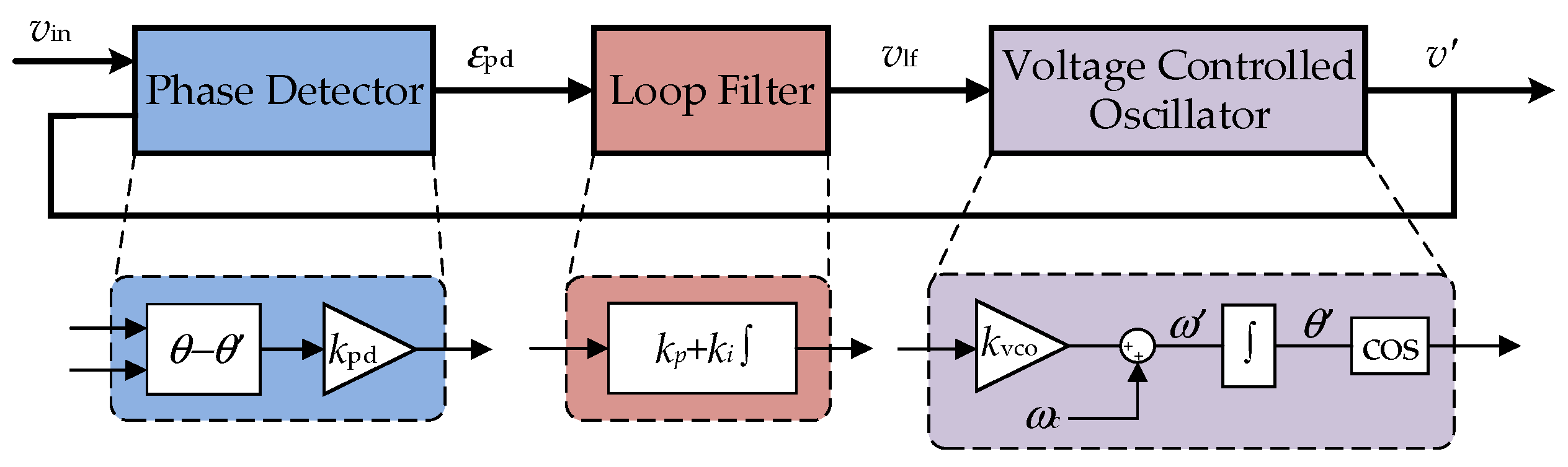
Figure 4.
General structure of the Enhanced PLL (EPLL).

Figure 5.
General structure of the Second-Order Generalized Integrator-based PLL (SOGI-PLL): (a) entire PLL structure; (b) the orthogonal signal generator (OSG)-based Phase Detector (PD).
Figure 5.
General structure of the Second-Order Generalized Integrator-based PLL (SOGI-PLL): (a) entire PLL structure; (b) the orthogonal signal generator (OSG)-based Phase Detector (PD).

Figure 6.
Performance comparison of the selected PLLs under a grid voltage fault with a 0.6 p.u. voltage drop: (a) grid voltage; (b) PLL estimated voltage amplitude output; (c) PLL estimated frequency output.
Figure 6.
Performance comparison of the selected PLLs under a grid voltage fault with a 0.6 p.u. voltage drop: (a) grid voltage; (b) PLL estimated voltage amplitude output; (c) PLL estimated frequency output.

Figure 7.
Performance comparison of the selected PLLs under a voltage sag depth of 100% (i.e., zero-voltage fault): (a) grid voltage; (b) PLL estimated voltage amplitude output; (c) PLL estimated frequency output.
Figure 7.
Performance comparison of the selected PLLs under a voltage sag depth of 100% (i.e., zero-voltage fault): (a) grid voltage; (b) PLL estimated voltage amplitude output; (c) PLL estimated frequency output.

Figure 8.
Low-voltage (and zero-voltage) ride-through requirements for grid-connected systems in different countries [15,16,17].

Figure 9.
Reactive current injection requirements under low-voltage ride-through/zero-voltage ride-through (LVRT/ZVRT) operations in China [16].
Figure 9.
Reactive current injection requirements under low-voltage ride-through/zero-voltage ride-through (LVRT/ZVRT) operations in China [16].

Figure 10.
Control diagram of the single-phase PV system based on the single-phase instantaneous active and reactive powers (PQ) theory.
Figure 10.
Control diagram of the single-phase PV system based on the single-phase instantaneous active and reactive powers (PQ) theory.
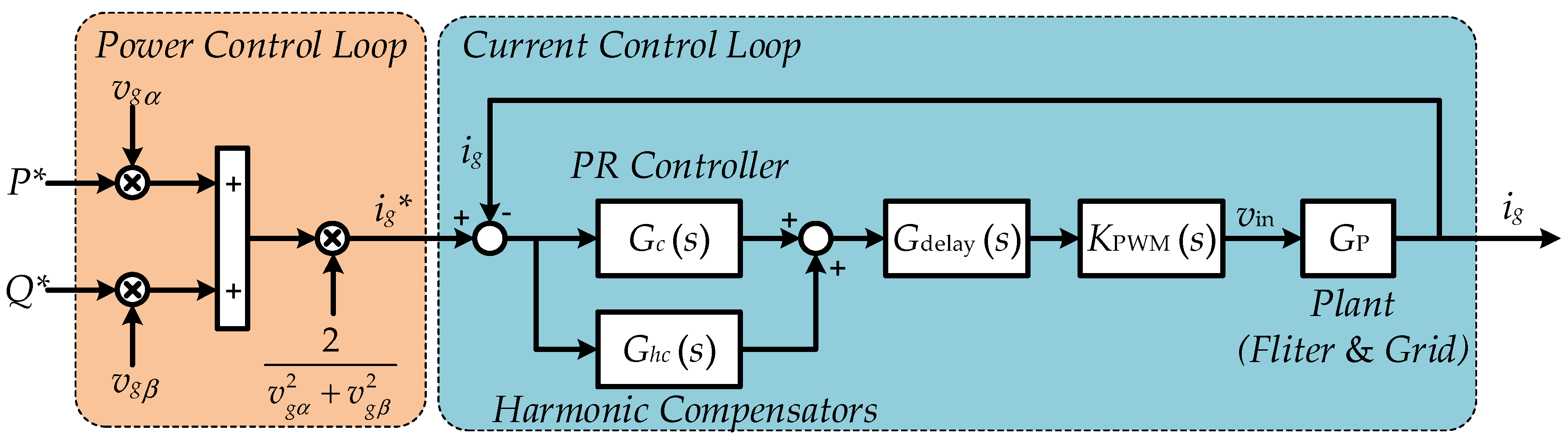
Figure 11.
Modified PLL structure to meet the requirement of the ZVRT operation.

Figure 12.
Performance of the PV system with normal SOGI-PLL during ZVRT: (a) grid voltage and current; (b) active and reactive power; (c) amplitude estimation; (d) frequency estimation.
Figure 12.
Performance of the PV system with normal SOGI-PLL during ZVRT: (a) grid voltage and current; (b) active and reactive power; (c) amplitude estimation; (d) frequency estimation.

Figure 13.
Performance of the PV system with modified PLL-based SOGI-OSG during ZVRT: (a) grid voltage and current; (b) active and reactive power; (c) amplitude estimation; (d) frequency estimation.
Figure 13.
Performance of the PV system with modified PLL-based SOGI-OSG during ZVRT: (a) grid voltage and current; (b) active and reactive power; (c) amplitude estimation; (d) frequency estimation.
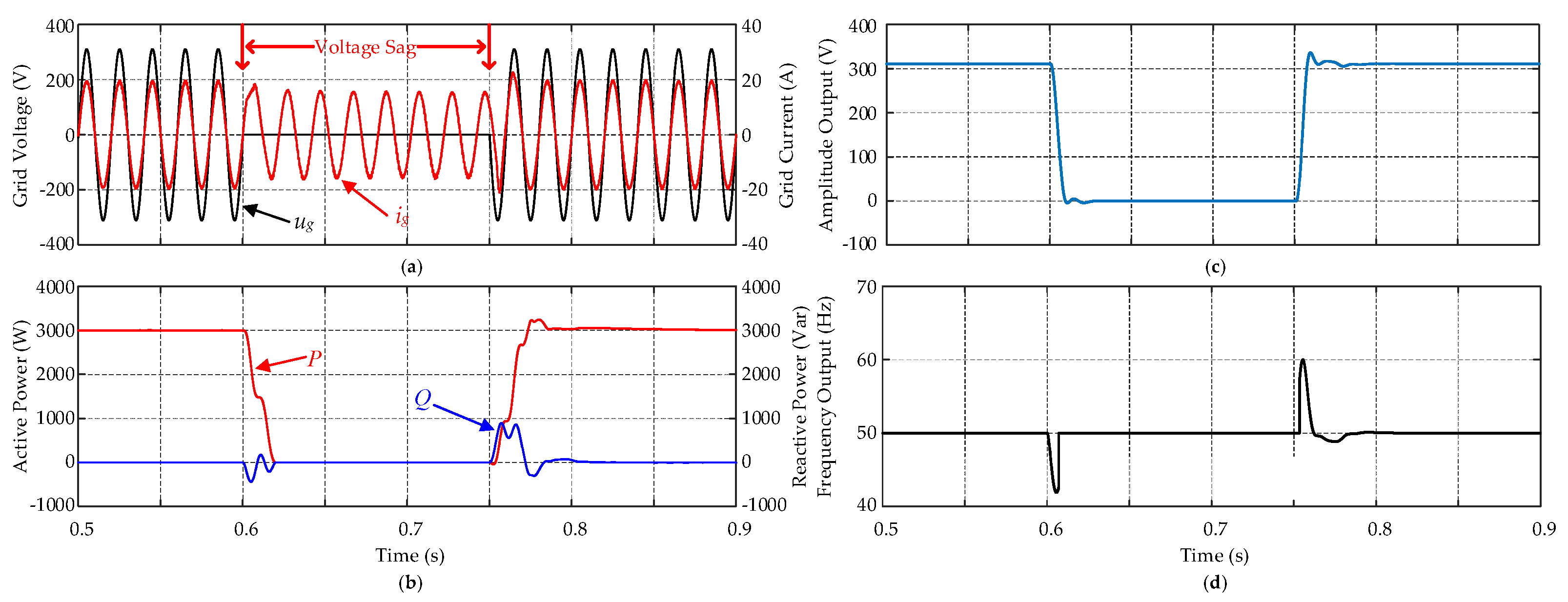
Figure 14.
A single-phase PV system under grid voltage fault with modified PLL-based SOGI-OSG: (a) grid voltage and current; (b) active and reactive power; (c) amplitude estimation; (d) frequency estimation.
Figure 14.
A single-phase PV system under grid voltage fault with modified PLL-based SOGI-OSG: (a) grid voltage and current; (b) active and reactive power; (c) amplitude estimation; (d) frequency estimation.

Table 1.
Parameters of the PLL system in the single-phase grid-connected system.
| Parameter Description | Value |
|---|---|
| Normal voltage amplitude | Vgm = 311 V |
| Normal grid frequency | ωg = 314 rad/s |
| Sampling and switching frequency | fs = fsf = 10 kHz |
| plus integral (PI) controller of Loop Filter (LF) for all (phase-locked loop) PLLs | kp = 112.7, ki = 1054 |
| Control parameters | kEPLL = 150, kSOGI = 0.707 |
Table 2.
Simulation parameters of the single-phase grid-connected PV system.
| Parameter Description | Value |
|---|---|
| Normal voltage amplitude | Vgm = 311 V |
| Normal grid frequency | ωg = 314 rad/s |
| Sampling and switching frequency | fs = fsf = 10 kHz |
| PV rated power | Pmax = 3 kW (i.e., 1.5 kW/PV string) |
| DC-link capacitor | CDC = 3000 μF |
| LCL filter | L1 = 3.6 mH, C = 2.35 μF, L2 = 4 mH |
| Hybrid proportional resonant (PR) and harmonic compensator (HC) controller | kp = 65, ki = 5000, kih = 500 |
© 2017 by the authors. Licensee MDPI, Basel, Switzerland. This article is an open access article distributed under the terms and conditions of the Creative Commons Attribution (CC BY) license (http://creativecommons.org/licenses/by/4.0/).
Share and Cite
MDPI and ACS Style
Zhang, Z.; Yang, Y.; Ma, R.; Blaabjerg, F. Zero-Voltage Ride-Through Capability of Single-Phase Grid-Connected Photovoltaic Systems. Appl. Sci. 2017, 7, 315. https://doi.org/10.3390/app7040315
AMA Style
Zhang Z, Yang Y, Ma R, Blaabjerg F. Zero-Voltage Ride-Through Capability of Single-Phase Grid-Connected Photovoltaic Systems. Applied Sciences. 2017; 7(4):315. https://doi.org/10.3390/app7040315
Chicago/Turabian StyleZhang, Zhen, Yongheng Yang, Ruiqing Ma, and Frede Blaabjerg. 2017. "Zero-Voltage Ride-Through Capability of Single-Phase Grid-Connected Photovoltaic Systems" Applied Sciences 7, no. 4: 315. https://doi.org/10.3390/app7040315
Note that from the first issue of 2016, this journal uses article numbers instead of page numbers. See further details here.