Article

Selected Issues of the Indicating Measurements in a Spark Ignition Engine with an Additional Expansion Process

Institute of Automobiles and Internal Combustion Engines, Division of Mechatronics, Cracow University of Technology, Al. Jana Pawla II 37, 31-864 Kraków, Poland
Appl. Sci. 2017, 7(3), 295; https://doi.org/10.3390/app7030295
Submission received: 1 February 2017 / Revised: 14 March 2017 / Accepted: 14 March 2017 / Published: 17 March 2017
(This article belongs to the Special Issue Internal Combustion Engines (ICE) for Ground Transport)

Abstract

:
The paper presents the results of research on the turbocharged spark ignition engine with additional exhaust expansion in a separate cylinder, which is commonly known as the five-stroke engine. The research engine has been constructed based on the four cylinder engine in which two outer cylinders work as the fired cylinders, while two internally connected inner cylinders constitute the volume of the additional expansion process. The engine represents a powertrain realizing an ultra-expansion cycle. The purpose of the study was to find an effective additional expansion process in the five-stroke engine. Cylinder-pressure indicating measurements were carried out for one of the fired cylinders and the additional expansion cylinder. The study was performed for over 20 different points on the engine operation map. This allowed us to determine a dependence between the pressure indicated in the fired cylinders and in the additional expansion cylinders. A function of the mean pressure indicated in the additional expansion cylinder versus a brake mean effective pressure was also presented. This showed a load threshold from which the work of the cylinders of additional expansion produced benefits for the output of the experimental engine. The issues of mechanical efficiency and effective efficiency of this engine were also discussed.

Graphical Abstract

1. Introduction

Spark ignition engines, which have been used in motor vehicles for over 140 years, still have a relatively low effective efficiency of conversion of fuel combustion energy into mechanical energy of rotation, despite significant developments. The best spark ignition engines used in motor vehicles currently obtain a peak effective efficiency of about 40% [1], what means that in the best case scenario, 60% of the energy delivered with the fuel is lost. In the case of low engine load, the loss of energy may exceed 80% of the value resulting from fuel combustion. To solve this and other problems, the European Commission has initiatives aimed at obtaining automotive engines with significantly increased efficiency. A peak thermal conversion efficiency of more than 50% is expected for engines developed in the Horizon 2020 Program [2]. However, at the moment this is only one of the targets for R&D projects which will be finished in the years 2020 to 2021, so an implementation of the developed engines for mass production will undoubtedly take place in the next few years. There are many different methods to improve this situation. It is worth mentioning here the most important methods, such as direct injection, thermal insulation of the combustion chamber, turbocharging, downsizing, downspeeding, the implementation of exhaust energy recovery using thermoelectric generators [3], or the advanced mechatronic systems, such as variable valve timing or continuously variable valve lift.
Among the ways to improve the effective efficiency (fuel conversion efficiency) of an internal combustion engine, an interesting method is to increase the expansion ratio to be significantly higher than the compression ratio of the engine. This leads to a significant increase in the thermal efficiency of the theoretical comparative cycle of the engine [4], but also gives tangible benefits in the effective efficiency of the engine performing such a cycle [5]. Figure 1 presents the concept of using an increased expansion ratio to improve the efficiency of an internal combustion engine. In a particular case, the working medium pressure can be decreased to match the ambient pressure.
Differentiation of the compression and expansion ratios of the engine may be accomplished in several ways. The first well-known solution was developed by the English engineer James Atkinson in the second half of the nineteenth century [6]. The engine concept by Atkinson was characterized by shorter intake and compression strokes than the power and exhaust strokes. This solution, however, was a significant disadvantage due to the sophisticated crank mechanism with respect to classical four-stroke engine. The increased interest in construction solutions of engines with increased expansion occurred in the second half of the twentieth century, when the concept by Ralph Miller [7] was developed. This concept was based on the classic four-stroke engine, but with suitably modified valve timing so as to get a reduced effective length of the compression stroke—Late Intake Valve Closing—or by reducing the degree of filling of the cylinder in a supercharged engine with an additional charge cooling by expansion in the intake stroke as a result of an Early Intake Valve Closing strategy. Engines performing an Atkinson/Miller cycle, but based on the classic four-stroke engine, have been used in motor vehicles since the mid-1990s [8]. Due to the specific characteristics of this type of solution, they often occur in vehicles with hybrid drive systems, diesel locomotives, and in industrial applications [9], where the engine operates with an average high load. The Atkinson cycle is also used in modern engines for conventional propulsion systems in order to reduce pumping losses in the low load region [10]. Research and development of engines performing Atkinson/Miller cycles are also carried out in Poland at several universities [11,12].
An entirely different approach to the problem of an internal combustion engine with an expansion ratio greater than the compression ratio was applied in the five-stroke engine developed according to the concept by Gerhard Schmitz [13,14]. In this engine, a significantly increased expansion is done after the exhaust process by a second expansion of the working medium in a separate cylinder. This cylinder has a displacement volume that is about twice as high in comparison to the cylinder where the combustion occurs. The engine provides practically unlimited possibilities in terms of establishing the compression and expansion ratios, without losing a significant part of the displacement volume of a working cylinder, as it is a classic engine implementing a Atkinson/Miller cycle.

Five-Stroke Engine Developed at Cracow University of Technology

In the years 2012–2014 at the Cracow University of Technology (CUT), an engine which worked according to the concept of Gerhard Schmitz [13] was developed. The main difference of this engine is the fact that it was not designed from scratch as a new engine, but its design was based on the classic four-stroke engine [15]. The tested engine was based on a mass-produced four-cylinder turbocharged spark ignition engine and a displacement volume of 2.0 L [16]. The concept of retrofitting the classic engine to five-stroke is shown in Figure 2.
As may be seen in the figure above, the engine after modification has two fired cylinders operating in a classical four-stroke mode with a phase shift of 360 Crank Angle Degrees (CAD), while cylinders No. 2 and 3 are permanently connected by the channel in the cylinder head where the process of additional expansion of the working medium occurs. These cylinders work as one in the two-stroke mode and are filled by exhaust gasses alternately from cylinder No. 1 and cylinder No. 4. The research engine has 4 valves per cylinder.
During the development of the engine with the additional expansion of exhaust gas, a thermodynamic cycle taking into account the specific characteristics of the tested engine was proposed [17]. Extensive simulation studies of a similar engine, but with a single-cylinder of additional expansion, was also carried out by Li et al. at Shanghai Jiao Tong University [18,19]. Initial simulation studies on a five-stroke engine were also performed by Palanivendhan et al. [20].

2. Materials and Methods
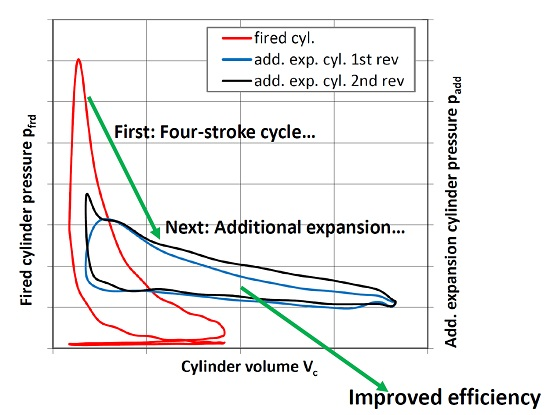
2.1. Background

The described engine has a high overall expansion ratio (εdcp) of the cylinder charge equal to 21. This value results from the fact that the compression and expansion ratios of the fired cylinders of the engine are equal to 10.5. The volume of the additional expansion cylinders at Bottom Dead Center (BDC), at the end of the second expansion, is twice as high as the volume of the gas at the end of the first expansion. The mentioned value of εdcp allows us to obtain a relatively high degree of energy recovery of the exhaust gas in the additional expansion cylinders at wide open throttle (WOT). In one study [5], the results of the theoretical calculations of the increase of the thermal efficiency of an engine cycle with the additional expansion were presented. To standardize the analysis of the engine cycle, processes are described as though the additional expansion was carried out in the same working volume. In the Otto-cycle, in which the compression and expansion ratios are the same, the thermal efficiency of the cycle is independent of the amount of heat added to the cycle. In the cycle in which the expansion ratio is higher than the compression ratio (e.g., five-stroke engine cycle), the increase in thermal efficiency is higher with more heat is added to the cycle. Under some simplification, the heat added to the theoretical cycle may be identified as the load of a real engine, so the higher the load, the higher the increase in the efficiency can be expected. On the other hand, in the real engine at partial load, when the cylinder pressure does not reach high values, the additional expansion process may give a charge pressure lower than the ambient pressure, which causes negative work and energy losses. In this situation, you should take into account that the cylinders of additional expansion, instead of giving additional power to the engine shaft, will be required to bring the power from the fired cylinders, which is a highly undesirable phenomenon for obvious reasons. The idea of an additional expansion process carried out in a separate cylinder together with the undesirable phenomenon of expansion below the ambient pressure in some cylinders is shown in Figure 3. As seen in the figure above, when the maximum pressure of the cycle is too low, a vacuum occurs in the additional expansion cylinders. This will produce an area of negative work of the cycle. When it becomes dominant over the rest of the cycle of the second expansion, it turns out that the overall balance of the additional expansion cylinder is negative—instead of giving power to the engine shaft, it will require its delivery and will act as an additional load of the engine, decreasing its efficiency.
In addition, in the five-stroke engine, the volume of the transfer port connecting the fired cylinder with the cylinder of an additional expansion is a parasitic volume, because expansion of exhaust gases occurring there causes the loss of part of the energy. In an ideal situation, this volume should be equal to 0. In practice, this is impossible due to the constraints of the conventional engine arrangement. Similarly, it would be preferable that the volume of the chamber above the piston in the cylinder of the additional expansion would be as small as possible. Unfortunately, in the tested engine, improvement of these parameters was not feasible, because during the construction of the test engine, a modified cylinder head of the original mass-produced engine was used.

2.2. Purpose of the Work

The purpose of this work was to evaluate the relationship between the indicated mean effective pressure of the fired cylinders (IMEPfrd) and the indicated mean effective pressure of the additional expansion cylinders (IMEPadd) of the tested engine, depending on the load and rotational speed of the engine. This approach allows us to estimate the load level below which the operation of the engine with the additional expansion of exhaust gases is not fully consistent with the main assumptions of such an engine, i.e., when an additional expansion process does not bring a positive effect. The results of this research also allow us to assess the mechanical efficiency of the tested engine and to show how the effective efficiency of the engine changes in various test conditions.

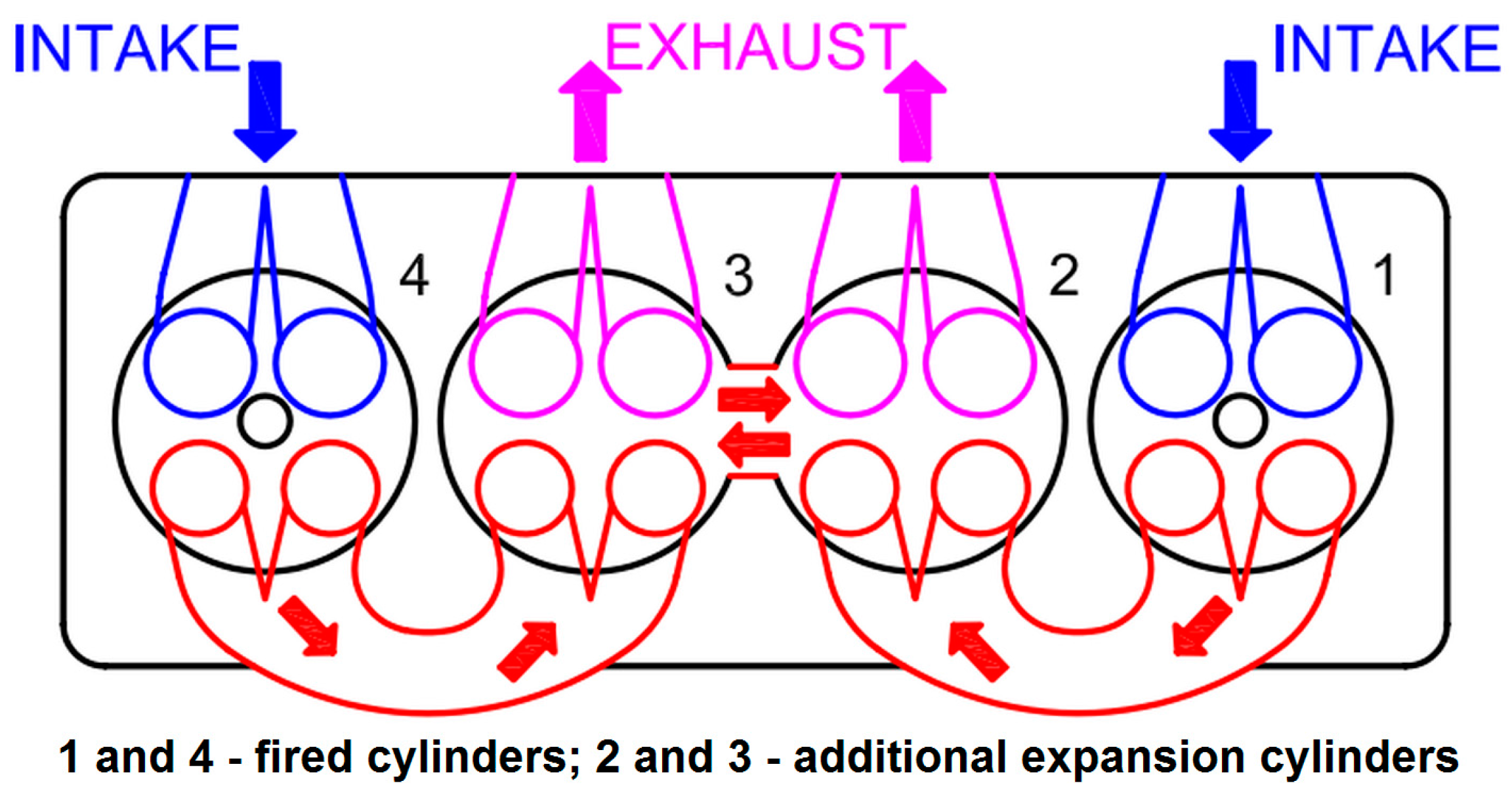
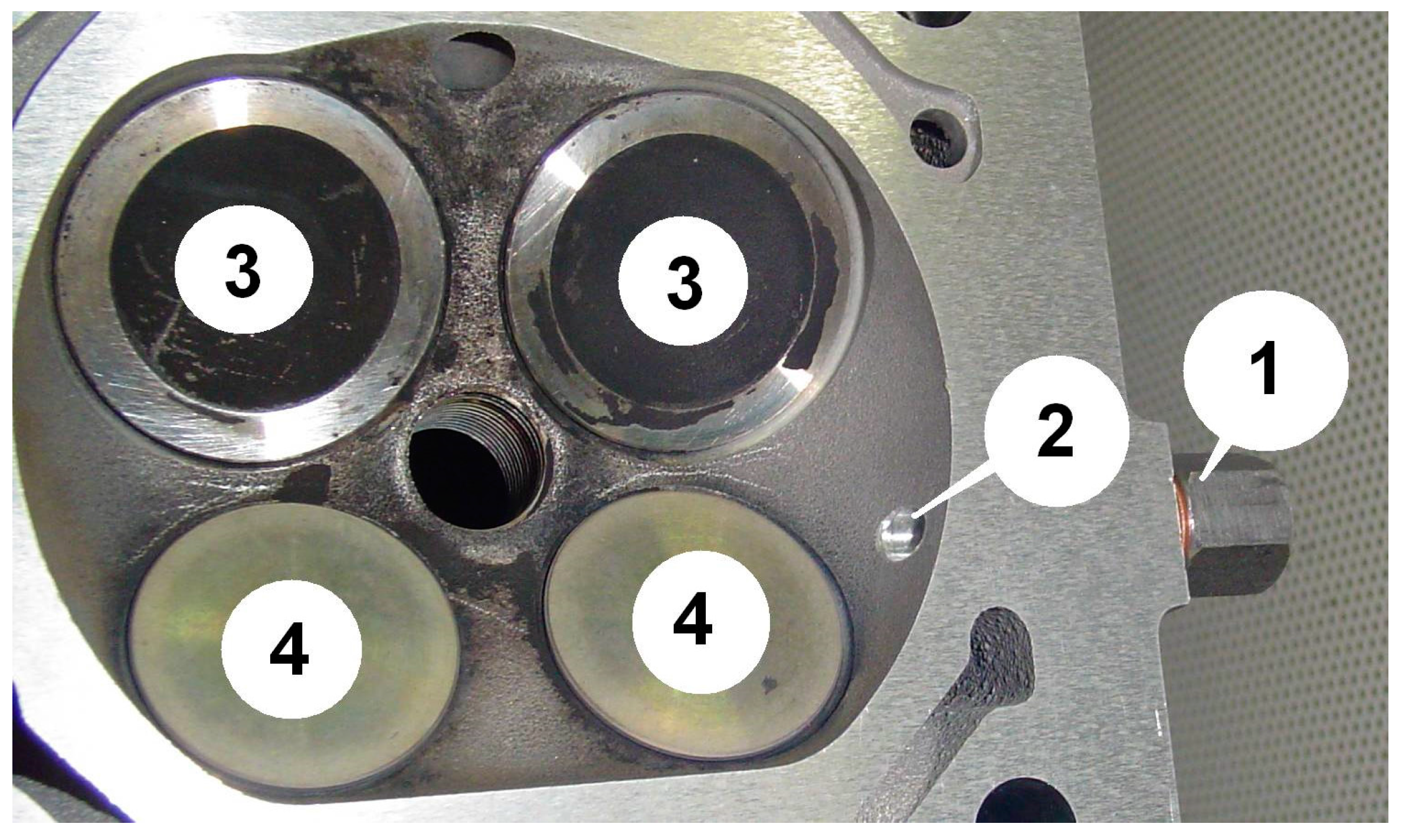
2.3. Specific Features of the Test Engine
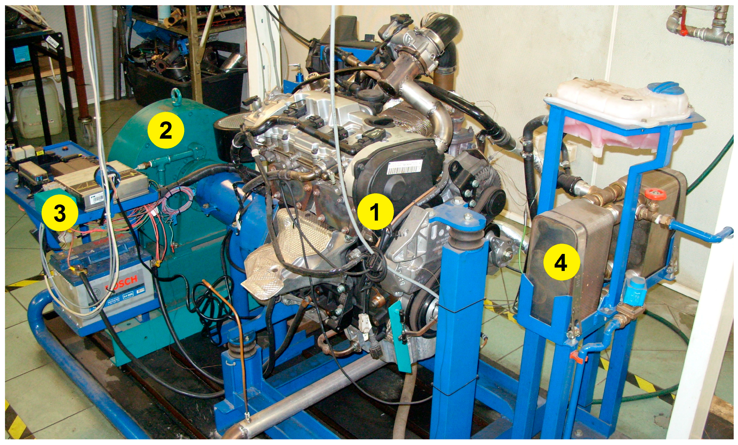
As mentioned above, the basis for the development of the test engine was a mass-produced four-cylinder turbocharged spark-ignition engine. This engine is equipped with a gasoline direct injection system. The engine adaptation for this research was mainly focused on the modification of the cylinder head and camshaft. A different turbocharger dedicated to the engine with a smaller displacement was used. The control of the boost pressure was done through the wastegate valve integrated in the turbine housing. For the test engine, the exhaust and intake manifolds were designed and manufactured. The test engine is fully autonomous, which means that the power to drive the high-pressure fuel pump, alternator, water, and oil pumps is derived from the engine rather than from external sources. Basic technical data of the engine are summarized in Table 1.
An engine management system (EMS) was built based on the stand alone AEM controller cooperating with the wide-band oxygen sensor. This EMS allowed us to change the operating parameters of the engine in real time during operation. High-pressure fuel injectors supplied with increased voltage were controlled using the Denso injector driver, because the EMS only allowed us to control high-resistance injectors.
Implementation of the engine concept presented in the scheme in Figure 2 required us to also develop modified camshafts, which provided valve timing as shown in Figure 4.

2.4. The Test Stand

The engine was mounted on a test stand with an Eddy-current brake dynamometer with a nominal power of 100 kW. A brake controller has a module for measuring and recording the temperature measured at selected positions. Fuel consumption measurement was conducted using a gravimetric method with electronic registration of instantaneous values of this parameter. Figure 5 shows a general view of the test bench.

2.5. Methodology for Measurement of the In-Cylinder Pressure

Pressure measurements in the fired cylinder and the additional expansion cylinder were carried out by the use of an optical sensor type Optrand AutoPSI-TC (D822D6-SP) with temperature-compensated output signal [21]. The pressure sensor with a threaded adapter was fitted to the combustion chamber of the fired cylinder (No. 4) through the drilled hole in its side surface. The hole was machined parallel to the bottom plane of the cylinder head.
Figure 6 shows a photo of the combustion chamber of the fired cylinder with a visible hole for in-cylinder pressure measurement and the adapter for the pressure sensor.
The view of the pressure sensor installed in the fired cylinder of the test engine is shown in Figure 7.
The in-cylinder pressure sensor for the cylinders of additional expansion was installed in cylinder No. 3 to the adapter mounted in the place of the spark plug. The sensors were able to measure the combustion pressure up to 10 MPa (with a possible short-term overload of 50%) and sensitivity equal to 385.8 mV/MPa. In order to perform a correlation of the recorded waveform of the in-cylinder pressure with the momentary position of the crankshaft, an incremental encoder was mounted to the test engine. The encoder had a resolution of 360 pulses per 1 revolution with a separate output phase for the Top Dead Center (TDC) marker.
The registration of waveforms of the in-cylinder pressure of the fired and additional expansion cylinders using Optrand sensors was performed using a PC equipped with a multifunctional data acquisition card with a 14-bit resolution of Analog-to-Digital Converter (ADC). The data acquisition process was carried out using a specialized application developed for this purpose in the LabView environment. The results presented in the following parts of this work were obtained by averaging the data from dozens of engine cycles for each measurement point. The study was preceded by an experimental procedure of the encoder settings to TDC of the cylinder No. 1.

3. Results

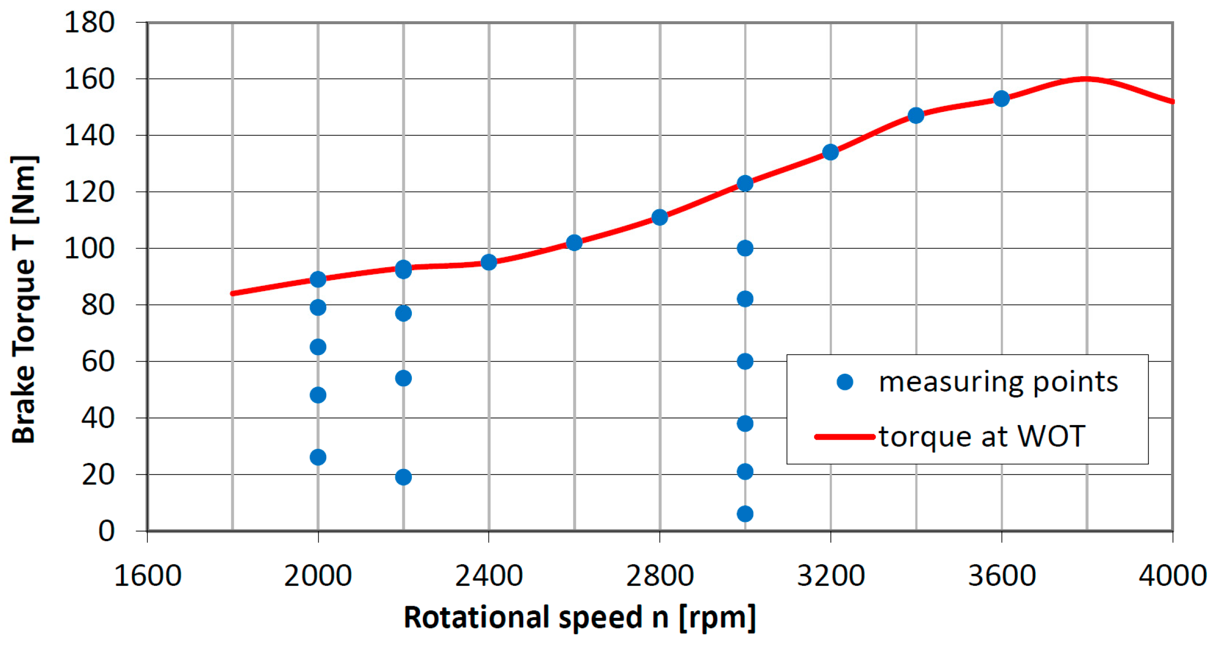
3.1. Range of the Implemented Research

Pressure measurements in the fired cylinder and additional expansion cylinder were carried out for the selected points of the engine operating map. The maximum boost pressure (pbst) was limited in the study to 0.9 bar. Figure 8 shows the operating map of the engine with the additional expansion of exhaust gas, with the highlighted points in which the in-cylinder pressure waveforms were recorded.
As shown in Figure 8, the in-cylinder pressure of the tested engine were measured at various values of the engine brake torque in the rotational speed (n) range from 2000 to 3600 rpm. During these tests, the engine throttle was fully open (WOT), and the wastegate valve of the exhaust gases remained closed. In addition, measurements of pressure in the cylinders at partial load for rotational speeds of 2000, 2200, and 3000 rpm were carried out. For the rotational speed of 3000 rpm of the engine, a minimum brake specific fuel consumption was achieved. During the course of the tests, a stoichiometric composition of the air-fuel mixture was maintained—relative air-to-fuel ratio was equal to 1 (rel. AFR). The engine was fueled with gasoline during the tests.

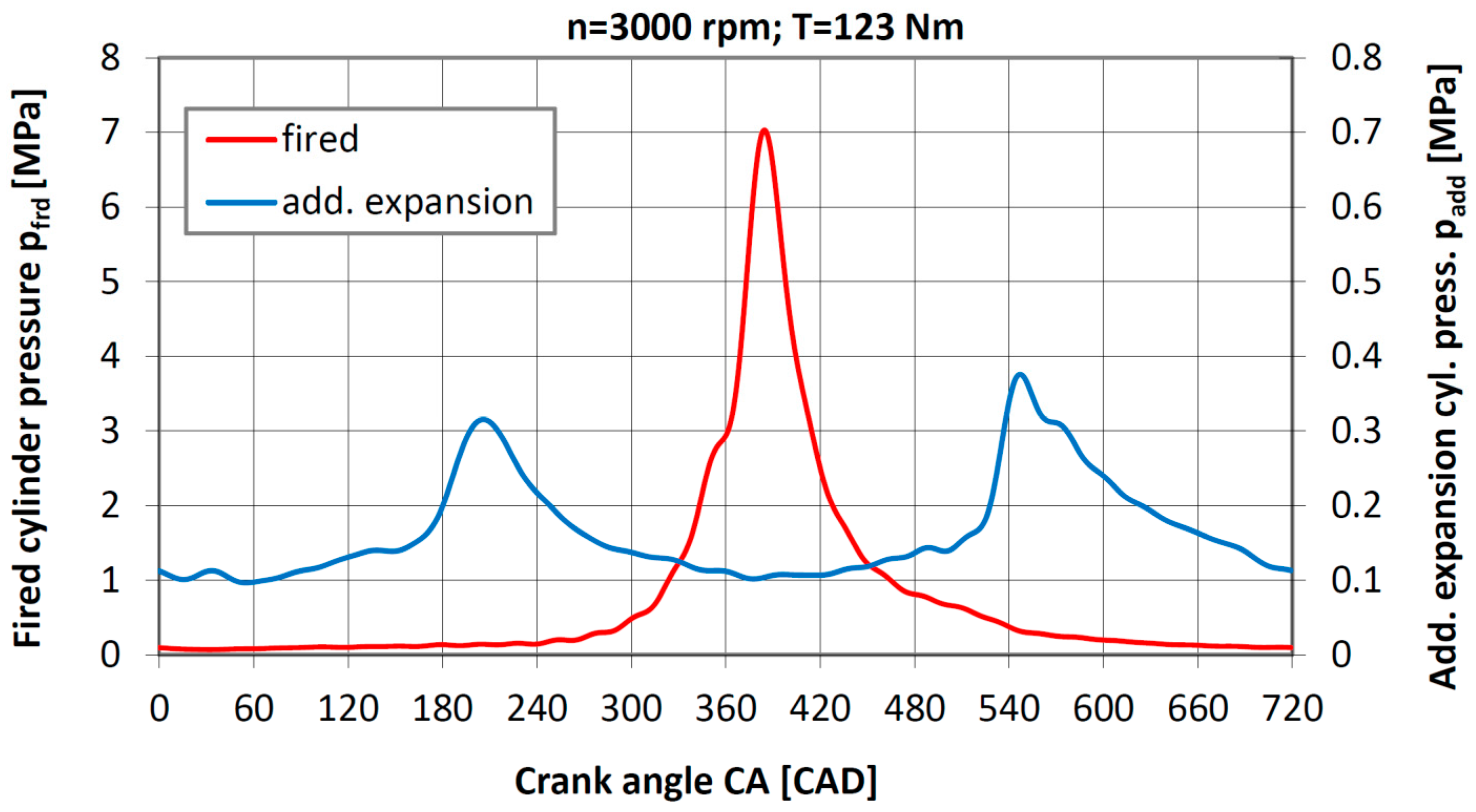
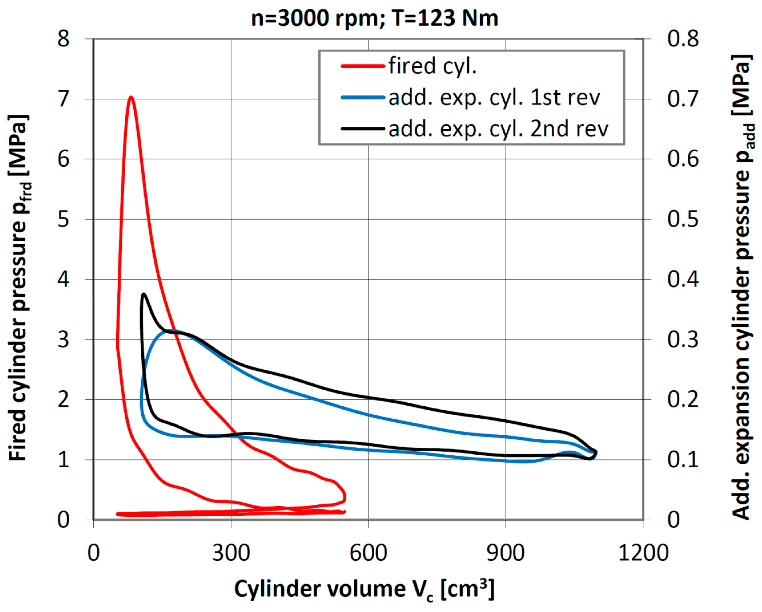
3.2. Measurements of the In-Cylinder Pressure of the Tested Engine

After testing the engine the results saved to the files were calculated in a popular spreadsheet software, but using a specialized template in order to shorten the calculation time. This allowed us to obtain the average waveforms of pressure in the fired cylinder and in the cylinders of additional expansion as a function of the crank angle (CA). Furthermore, after introducing the geometrical data of the engine into the calculation program, p-V diagrams were developed for the fired cylinders, as well as for the cylinders of the additional expansion. Development of the p-V indicator diagrams allowed the calculation of the indicated mean effective pressure and the indicated power for fired cylinders and additional expansion cylinders for each of the measurement points.
The following are examples of the work carried out on the recorded waveforms of in-cylinder pressure for the fired and additional expansion cylinders.
In Figure 9 the p-CA diagram of the engine with the additional-expansion registered for a full load 123 Nm at 3000 rpm rotational speed is presented. A turbocharger wastegate valve remained closed, and the boost pressure was 0.5 bar. The exhaust gas temperature measured at the outlet of the turbine had a value of 437 °C.
The peak pressure in the fired cylinder reached 7 MPa for the case above, for the position of the crankshaft at 380 CAD ATDC (Crank Angle Degrees) (After Top Dead Center). The difference in pressure peaks recorded in the cylinders of additional expansion in the case of filling by exhaust cylinder No. 3 from fired cylinder No. 4 and No. 1 (through cylinder No. 2 and the passage) was approximately 0.06 MPa.
The aforementioned difference in the value of the maximum pressure in the additional expansion cylinder for the crank angle of approximately 180 CAD and approximately 540 CAD are caused by throttling the flow in the connecting passage between the expansion cylinders 2 and 3. The pressure value obtained for 540 CAD occurs when the exhaust goes to the additional expansion cylinder No. 3 from the adjacent fired cylinder No. 4, in which the in-cylinder pressure is also measured. The pressure registered at 180 CAD resulted from filling the assembly of the cylinders of additional expansion by exhaust gases from cylinder No. 1. In this case, the exhaust gases were first delivered into cylinder 2, then through the connecting channel in the cylinder head to cylinder No. 3, where the measurement was carried out. During the calculation of the indicated work of the additional expansion cylinders, its value was determined in consideration of the fact that in the cylinders of additional expansion, the pressure is variable in a cyclic manner as described above.
In Figure 10, the in-cylinder pressure curves are shown as a function of cylinder volume (Vc) for the fired and additional expansion cylinders registered for a full load of 123 Nm at 3000 rpm rotational speed.
The assembly of additional expansion cylinders of the engine works in a two-stroke mode, therefore the in-cylinder pressure waveform shown in the above chart includes two complete processes of additional expansion and the exhaust process, as shown in the p-CA diagram. The values of the indicated mean effective pressure in the fired cylinder (IMEPfrd) and in the additional expansion cylinders (IMEPadd) were calculated by numerical integration of relevant areas of the p-V chart. These values were: IMEPfrd was equal to 1.72 MPa, and IMEPadd was equal to 0.08 MPa. The indicated power in the working cylinders (Pi_frd) was then calculated using Formula (1):
P i _ frd = 2 · IMEP frd · V frd · n 120000 ,   kW
The formula presented above takes into account the used units, including the speed and four-stroke nature of the work of the two working cylinders. Similarly, the formula for calculating the indicated power of the cylinder of additional expansion (Pi_add) is presented as Formula (2):
P i _ add = IMEP add · V add · n 60000 ,   kW
This formula takes into account that both cylinders of additional expansion work in a two-stroke mode as a single working volume. The calculated value of the indicated power of the fired cylinders at this operating point is 42.77 kW, and the value of the indicated power in the cylinders of additional expansion is approximately 3.98 kW, which is more than 9% of the Pi_frd value.
A similar analysis of the waveforms of in-cylinder pressure for the fired and additional expansion cylinders was carried out for the results obtained in the other measuring points. This made it possible to determine the relationship between IMEPfrd and IMEPadd. This is shown graphically in the form of a plot in Figure 11.
The course has been approximated by a straight line, and the equation is presented in the chart. The achieved value for the IMEPadd/IMEPfrd ratio is greater when the IMEPfrd is higher. The highest value (the last point on the top of the graph) is 0.063. With regards to the relations of the indicated power, the mentioned ratio will be about 12.6%, as the additional expansion cylinders operate in a two-stroke mode. This is an important energy recovery ratio in the additional expansion process of the working medium.
In order to determine the load of the five-stroke engine from which the cylinders of additional expansion start to give power to the output, the dependence of the Brake Mean Effective Pressure (BMEP) as a function of the Indicated Mean Effective Pressure of the additional expansion cylinders (IMEPadd) was defined. Figure 12 shows a graph of this function. Similarly, as in the previous case, the obtained waveform is approximated by a straight line whose equation is given in the chart.
BMEP values were determined from the value of the torque, taking into account the displacement volume of the fired cylinders (2 × Vfrd = 992 cm3). The volume of the cylinders of additional expansion cannot be taken into account while calculating BMEP, because there is no combustion process in these cylinders. The determination of this function was aimed at finding a load limit before which the additional expansion cylinders take power from the engine instead of delivering power to the engine. The value of the intercept of the function from Figure 12 is equal to about 0.6. This means that if the BMEP is lower than 0.6 MPa, then additional expansion cylinders require power from the engine. Above this value, the additional expansion process becomes positive for the engine work. Taking into account the volume of the cylinder, the engine, and the mechanical efficiency, this means that the assembly of the cylinders of additional expansion transmit additional power to the engine output from the time when the measured torque exceeds 60 Nm. This fact means that the five-stroke engine would be most suitable for applications where it would work mainly in the field of medium and high loads.

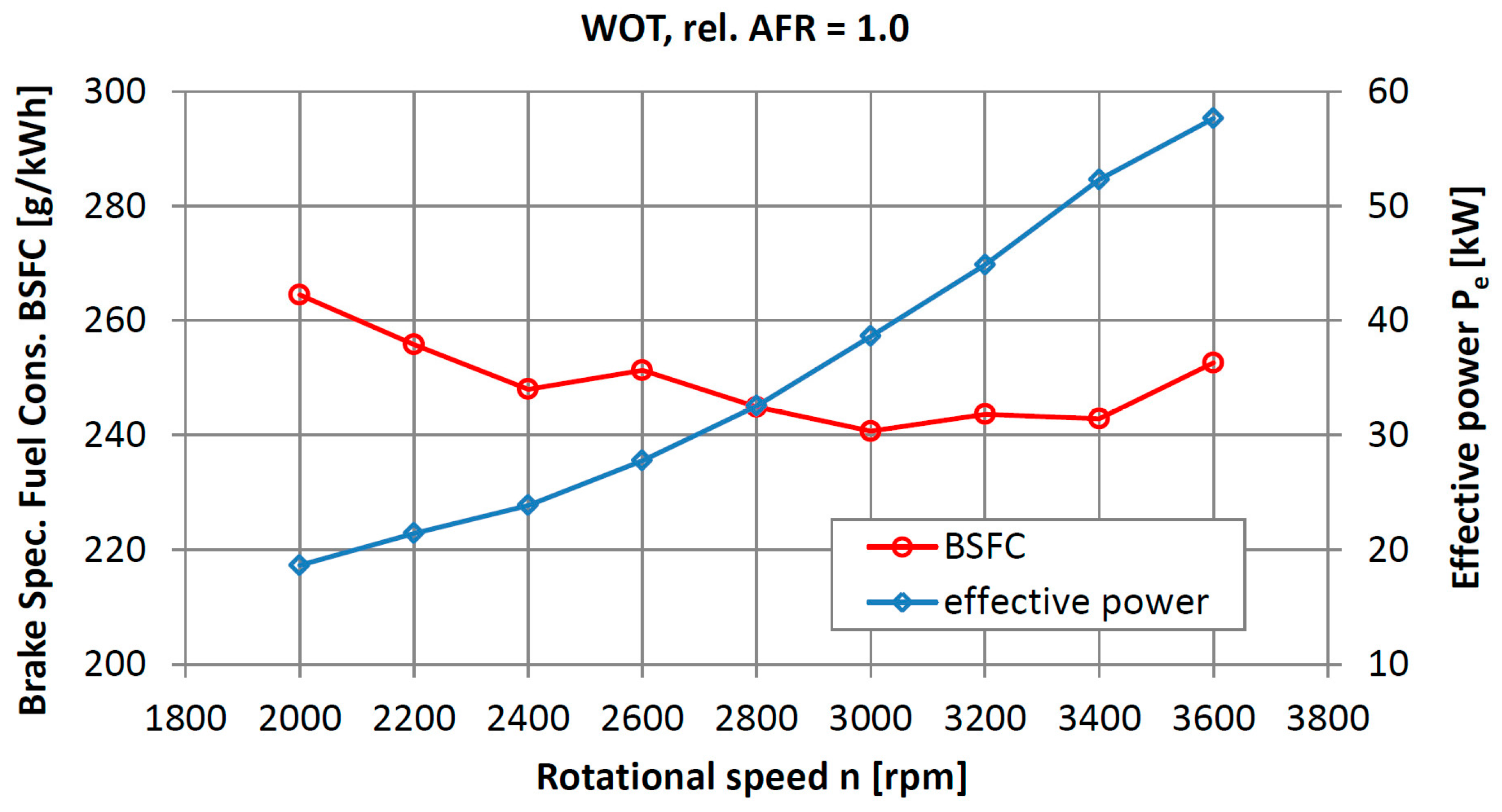
3.3. Brake Specific Fuel Consumption and Effective Power

The results of this research also allow us to determine the effective power (Pe) and Brake Specific Fuel Consumption (BSFC) of the engine. In Figure 13, the curves of BSFC and effective power as a function of engine rotational speed at wide open throttle (WOT) are presented. A stoichiometric air-fuel mixture composition was maintained.
The minimum value of the specific fuel consumption was 240 g/kW·h. This value was obtained at a speed of 3000 rpm and a boost pressure pbst of 0.5 bar. For higher values of the rotational speed, especially for 3600 rpm, the obtained value of the brake specific fuel consumption tended to increase, which resulted in a discontinuation of the tests for higher values of the rotational speed.

3.4. Mechanical Efficiency of the Tested Engine

For conventional internal combustion engines, calculations of the mechanical efficiency (ηm_cnv) based on the known indicated mean effective pressure do not pose any problems. This is described by Formula (3):
η m _ cnv = BMEP IMEP = P e P i ,
Brake Mean Effective Pressure at a certain rotational speed is determined by measuring the torque of the engine relative to a displacement volume of the engine and to the engine type, i.e., whether it is a two-stroke or four-stroke engine. Indicated Mean Effective Pressure is determined based on the measured in-cylinder pressure as a function of CA. For a multi-cylinder engine, the pressure is typically measured for one cylinder and it is assumed that all the other cylinders operate in the same way. For obvious reasons, for the classic engine, the BMEP/IMPEP ratio is exactly the same as the ratio of effective power (Pe) to the indicated power of the engine (Pi).
In the case of an engine with the additional expansion of exhaust gas in a separate cylinder, the situation becomes more complicated. Besides the cylinders, where a conventional four-stroke working cycle is carried out, the engine has a cylinder for the additional expansion of the exhaust, which should deliver work to the output of the engine. This cylinder is an integral part of the engine so its effect cannot be ignored in the analysis of the mechanical efficiency of the engine, because the calculated value of the mechanical efficiency would be artificially high and, in particular, the engine operating conditions could prove to be even higher than 1. Under the conditions of a sufficiently high load of the engine, where the cylinder of additional expansion provides additional power to the output, its indicated mean effective pressure is higher than zero. In the case of low engine load when the pressure of the exhaust gas going into the cylinder is low, the additional expansion cylinder requires additional propulsion from the engine, and the value of the indicated mean effective pressure becomes negative; of course, the same thing happens to the value of power indicated from the cylinder. Considering the case above, we conclude that the effect of the operation of the additional expansion cylinder has to be included in a certain way when determining the mechanical efficiency of the five-stroke engine. The values of IMEP for the fired and additional expansion cylinders are not additive. This happens because in a general case they relate the different displacement volumes, and it should be noted that the fired cylinders operate in four-stroke mode, while the cylinders of additional expansion operate in two-stroke mode. Avoiding this problem is possible by calculating the mechanical efficiency from the calculated values of the effective power and the indicated power of the engine. To determine the mechanical efficiency of the five-stroke engine, the author of this paper proposes a summation of the indicated power for the fired cylinders Pi_frd and indicated power of the cylinders of additional expansion Pi_add when the indicated power Pi_add is greater than zero—Formula (4). In contrast, if the indicated power of the cylinder of additional expansion Pi_add is zero or less than zero, it acts as a load (like the oil pump, water pump, and alternator), and in this situation the indicated power of the cylinder of additional expansion Pi_add should not be taken into account while calculating the mechanical efficiency of the engine with an additional expansion of exhaust gas in a separate cylinder (ηm)—Formula (5).
for   P i _ add   >   0 , η m = P e P i _ frd + P i _ add ,
for   P i _ add     0 , η m = P e P i _ frd ,
Figure 14 shows curves of the mechanical efficiency of the engine with the additional expansion of the exhaust gases for various values of rotational speed and its dependence on the brake torque.
An analysis of the diagram indicates that the obtained value of the mechanical efficiency of the engine increases with engine load, reaching a value slightly larger than 0.8. This took place at the rotational speed of 3000 rpm, when the boost pressure pbst was 0.5 bar. It is also seen that in the analyzed range of the rotational speed of the engine, the mechanical efficiency does not depend significantly on the rotational speed.
Figure 15 presents charts of the effective efficiency and boost pressure of the tested engine versus the rotational speed at full throttle (WOT) and with a stoichiometric air-fuel mixture composition.
The maximum value of the mechanical efficiency of the tested engine was 85.5% and was recorded at a rotational speed of 3400 rpm. Above this value, the boost pressure increased to 0.9 bar, and the mechanical efficiency began to decrease. The effect of a significant increase in BSFC was also demonstrated (shown in Figure 13). The resulting course of the boost pressure indicates that the used turbocharger starts to work effectively with the tested engine at rotational speeds of 3000–3200 rpm.

4. Discussion

The results of the experimental test of the engine with an additional expansion of exhaust gases are presented in this study. After the analysis, the author attempted to compare the obtained results mainly to that from [14], which shows the results obtained for a similar engine, but which was designed and built from scratch. Summary of the results of the comparison is as follows:
  • During the tests, significant differences in the maximum pressure in the two cylinders of additional expansion were observed. These differences arise from the small area of the cross-section of the passage between the cylinders. This is a limitation of the base engine. In the developed engine, there are two smaller cylinders of additional expansion instead of one larger cylinder. Improvement of the existing motor can consist only of a larger cross-section of the channel, which connects the cylinders of additional expansion.
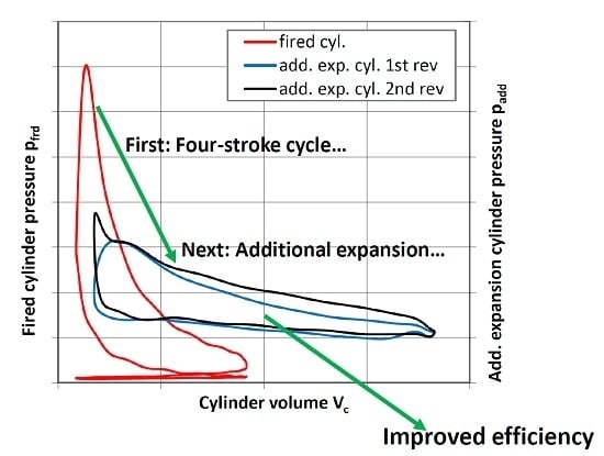
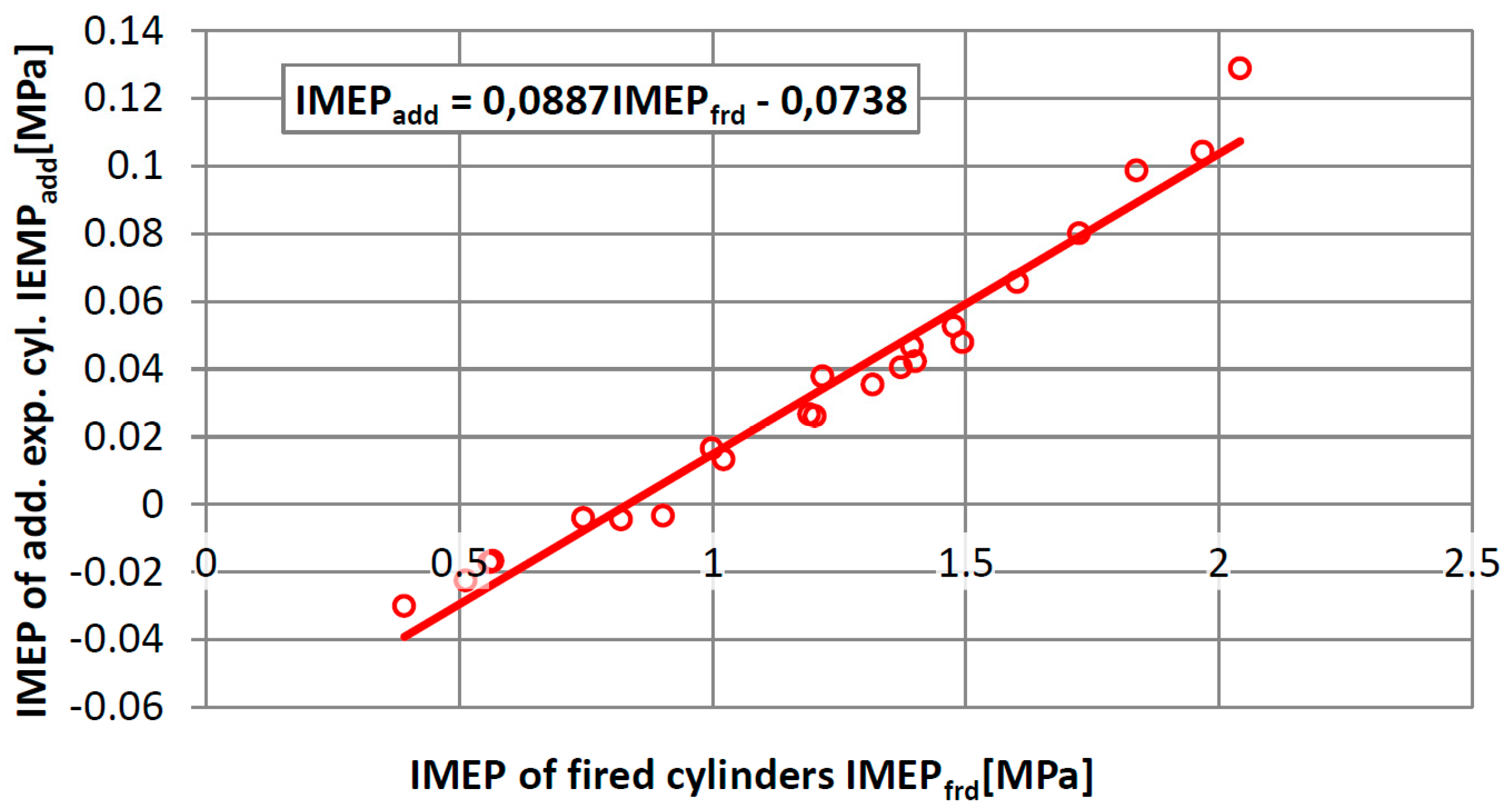
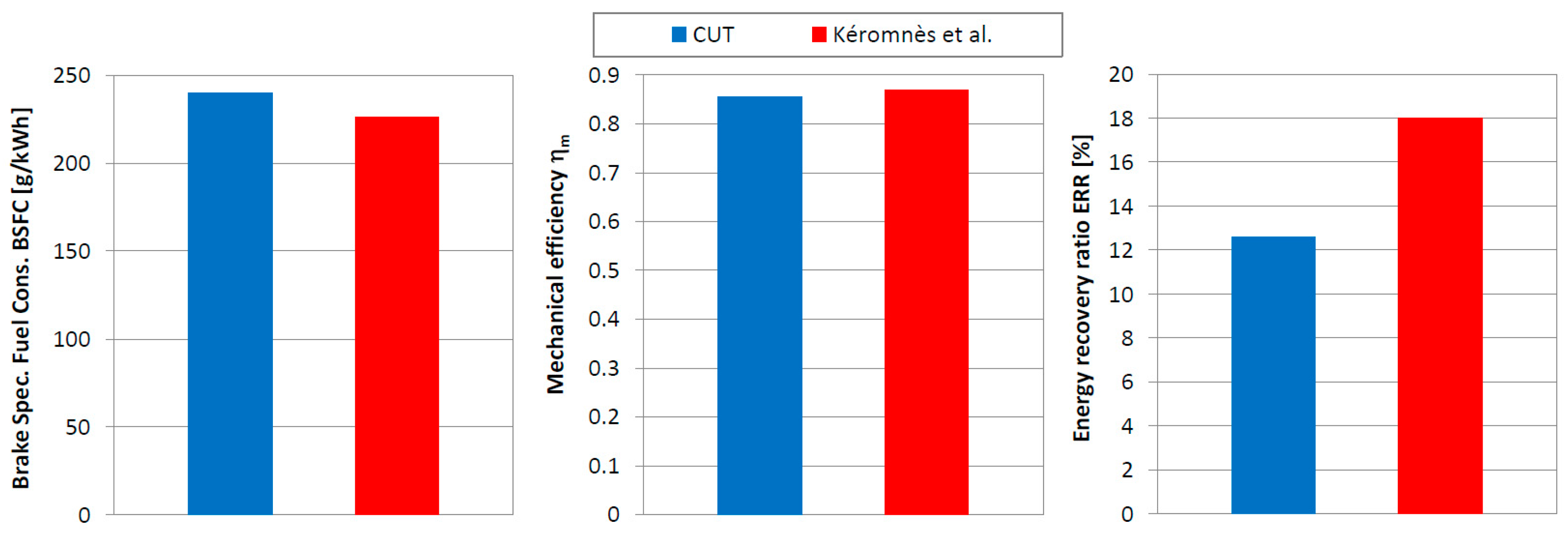
  • The energy recovery ratio—the indicated power of the additional expansion cylinders—is up to 12.6% of the indicated power of the fired cylinders. Obstacles to achieving better results were: high volume of the transfer ports between the fired cylinders and additional expansion cylinder, as well as the unchanged volume of the former combustion chambers in the cylinders of additional expansion, and also the division of the additional expansion volume into two cylinders. Kéromnès et al. showed a significantly higher ratio of the indicated work of the additional expansion cylinder to the indicated work of the fired cylinder. They obtained a value of about 18%—[14] (p. 265).
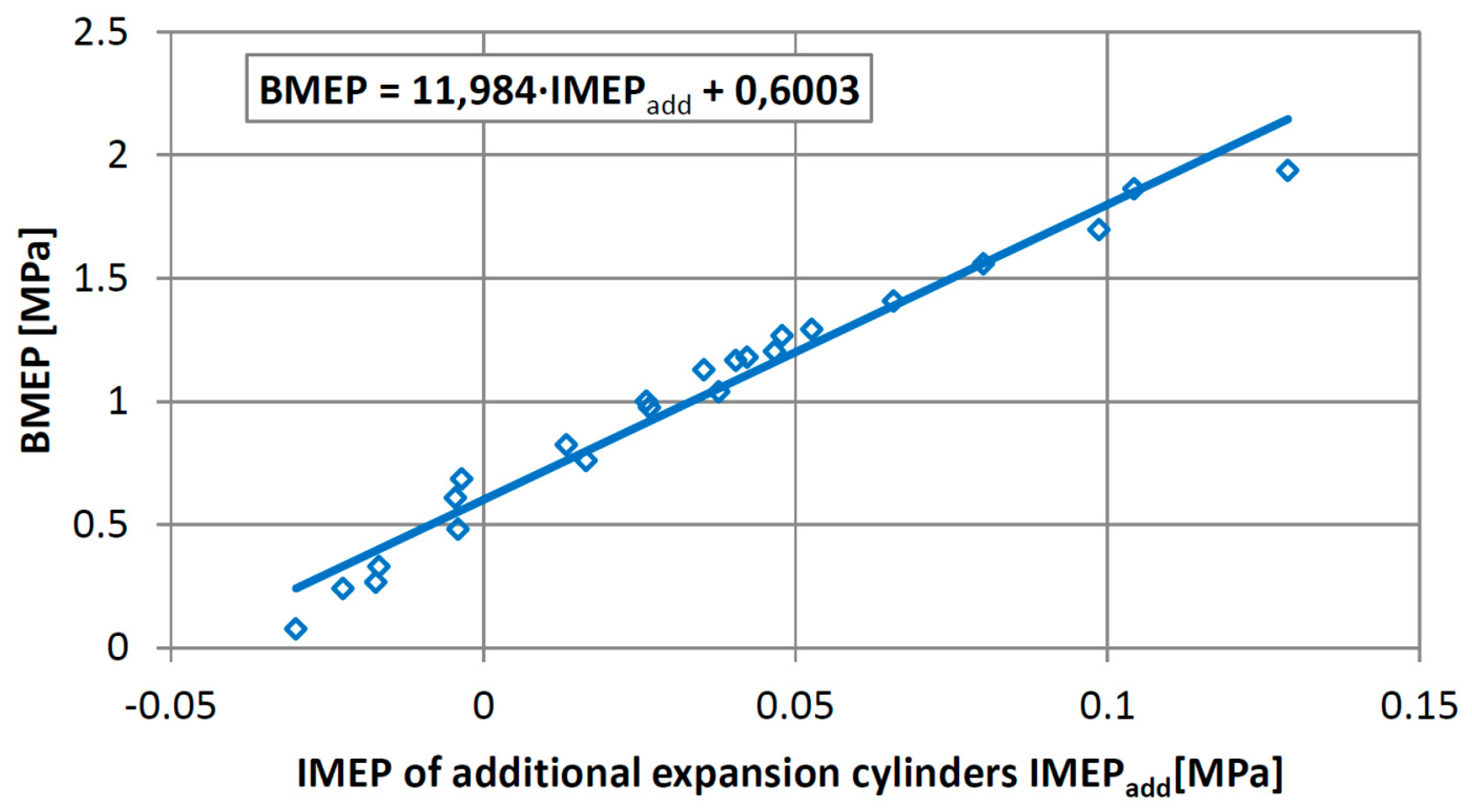
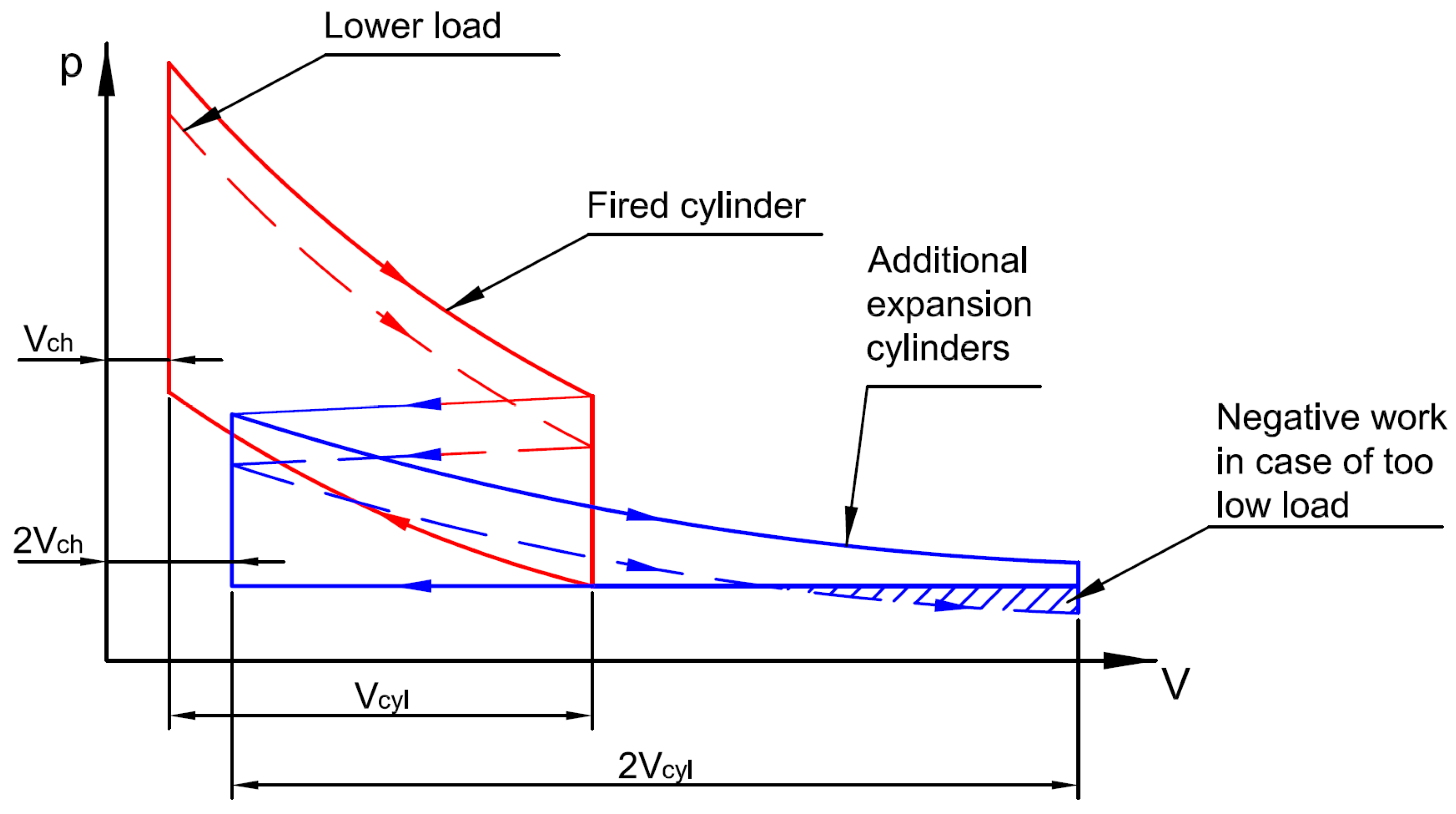
  • During the engine testing, a high value of load was obtained, from which the cylinders of additional expansion of the engine gave power to the output. This was about 60 Nm and was caused by the limitations of the above-mentioned structure of the base engine, mainly from the loss of energy in the parasitic volumes. Below 60 Nm of torque, the engine still operates at a relatively low BSFC, but is related to the effect of downsizing, instead of the additional effects of the second expansion of exhaust gas. This aspect of the five-stroke engine was not strongly emphasized in [14]. The problem of the selection of an appropriate displacement volume of the second expansion cylinder linked to this issue was analyzed by Li et al. in [18].
  • This research revealed an additional problem, which was not described in the work content; the increased consumption of oil lubricating the engine when working with low load. The increased consumption of lubricating oil is caused by the occurrence of negative pressure in the inlet channel of the turbine at the opening of the exhaust valves of the engine. This significantly changes the operation of an oil seal of the turbocharger rotor shaft and the sucking of oil into the exhaust system occurs.
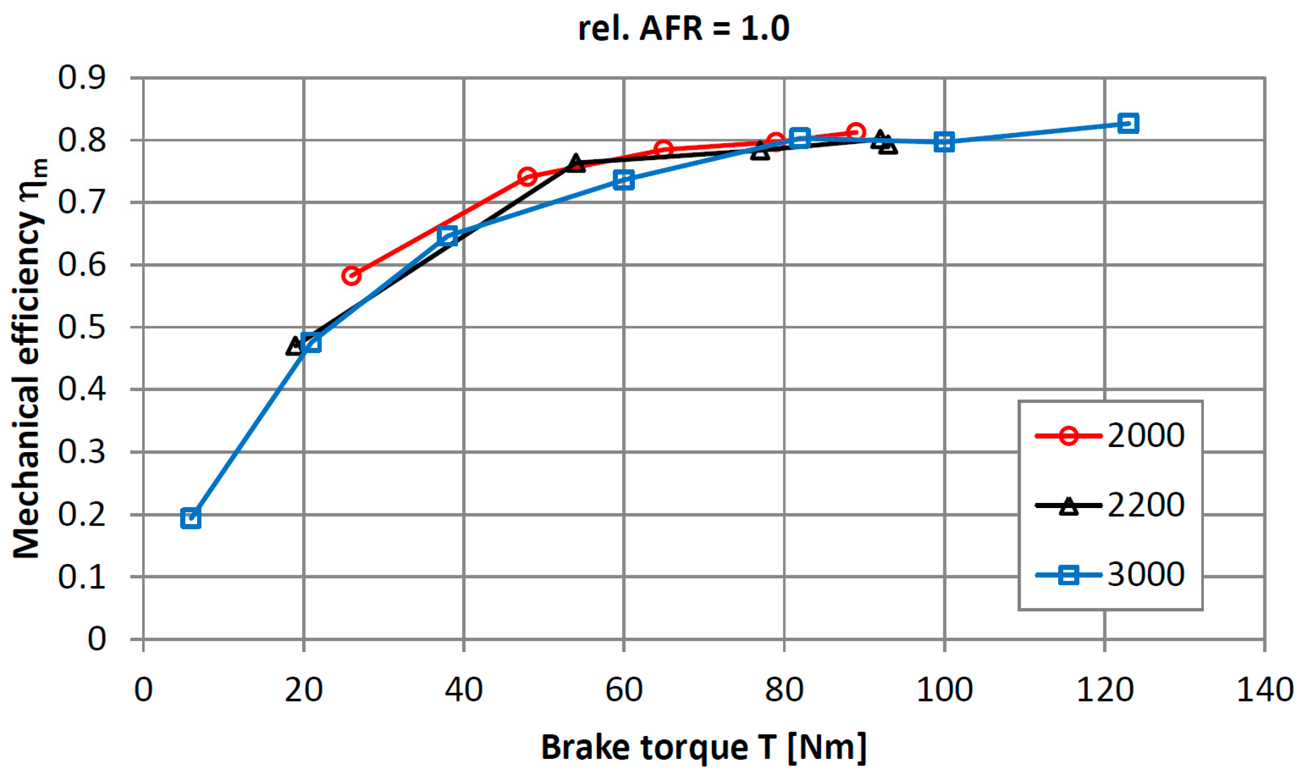
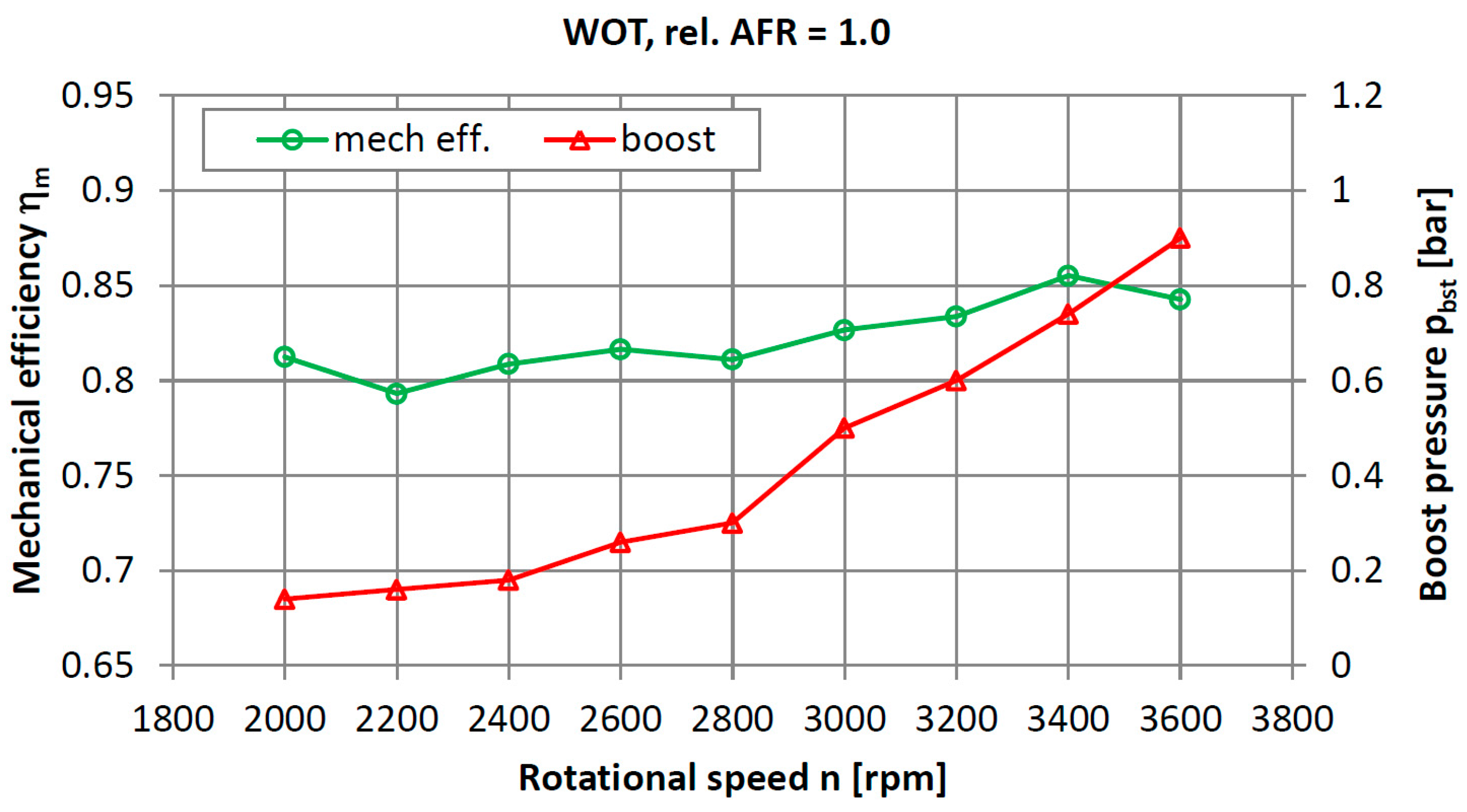
  • The maximum values of the mechanical efficiency of the engine achieved by the author correspond to the results presented in [14]. This indicates a good level of technical modification made to the engine.
  • The minimum brake specific fuel consumption amounted to 240 g/kWh. One should remember that the tested engine worked with all the equipment necessary for autonomous operation, i.e., with the alternator, oil pump, coolant pump, and the high pressure fuel pump. A low-pressure fuel pump was also supplied from the engine power grid. Kéromnès et al. obtained a BSFC of 226.4 g/kWh, but the engine was working without propelling an oil pump and a water pump, and probably also without the alternator. A drive of these devices by the engine undoubtedly caused an increase in the brake specific fuel consumption.
As a summary of this part of the work, Figure 16 shows the results of the above-described comparisons of these two engines, presented in graphical form.
Considering the obtained results, but also the indicated imperfections and limitations of the developed engine, the author plans for further development of the design. These activities will mostly cover:
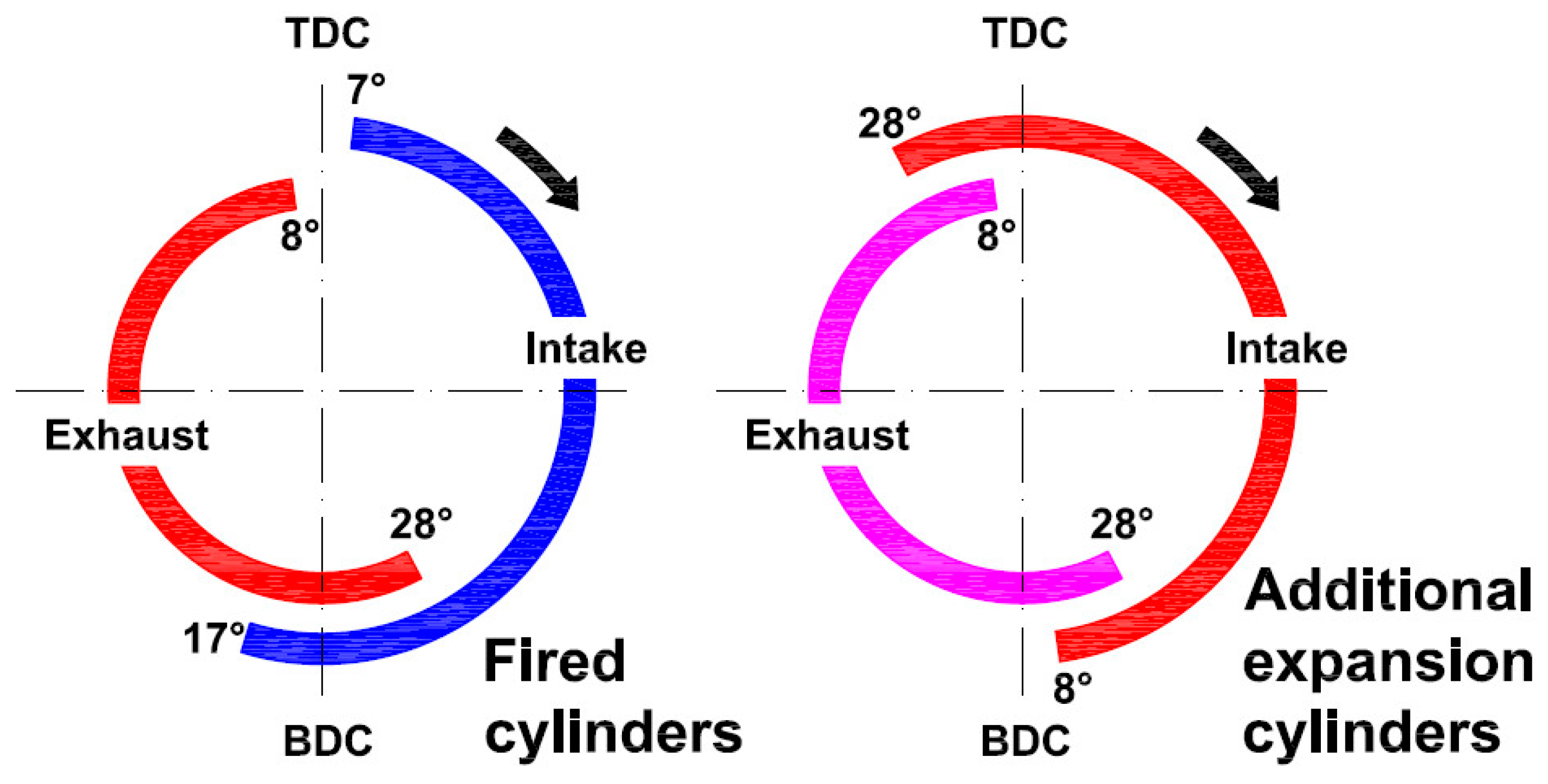
  • Simulations to optimize the valve timing of the tested engine, or the development of new camshafts. The current valve timing is based on four-stroke engine settings and is not optimized for the new engine with a significantly different design and performance.
  • An enlargement of the crossover passage between the additional expansion cylinders, and a reduction of the parasitic volume of the second expansion cylinders by the use of modified pistons, since it is the only modification to the combustion chambers of the cylinders of additional expansion that is possible to make in the developed engine.
  • Selection of a turbocharger more matched to the specific parameters of the engine with the additional expansion of the exhaust gas. The plan is to apply a different turbocharger controlled by the wastegate valve. The initial analysis of this issue indicated that a VNT-turbocharger may not be suitable for the tested engine.
  • Changing the method of control of the high fuel pressure—a pressure relief valve is currently used, which introduces a loss of power to the system. the plan is to develop a pressure control system by varying the flow rate of the high-pressure pump, similar to the base engine. This action requires the development of a separate electronic controller, because the used stand-alone engine management system does not offer such feasibility.
  • After improving the engine, emissions testing will be carried out and selection of the aftertreatment system will be made, taking into consideration the specificity of the engine.

5. Conclusions

Basing on the results of the research described in the paper, the following conclusions were formulated:
  • The results obtained by the author are so promising that despite the significant limitations in the feasibility of developing the design resulting from the adoption of a mass-produced four-cylinder engine as a base, he intends to lead its further development.
  • The engine developed according to the concept of the five-stroke engine has many advantages, especially if it is designed from scratch, but it also has some drawbacks that make it not quite suitable for use in the classical drive system of cars. At low loads, there are some problems, such as the expansion of the exhaust gas below the ambient pressure, which results in energy loss, or problems with the operation of the turbocharger.
  • Under heavy load, the engine achieves high efficiency while maintaining a high power-to-weight ratio. This makes this type of engine very well suited for applications where would it work with average high load, that is, for example, as a stationary electric generator or as an engine for the hybrid powertrain of a motor vehicle, in particular in series arrangement, but also under certain conditions for a power-split hybrid. A similar application field for such an engine is also indicated by the authors of study [14], who developed the five-stroke engine as the main power source for an extended-range electric vehicle or for a series-hybrid arrangement.

Acknowledgments

This research was conducted in the framework of task No. M-4/353/2016/DS, which was a subsidy for research granted by the Ministry of Science and Higher Education of the Republic of Poland. The author of the paper would like to thank Łukasz Rodak from Cracow University of Technology for support in the data acquisition process.

Conflicts of Interest

The author declares no conflict of interest. The founding sponsors had no role in the design of the study; in the collection, analyses, or interpretation of data; in the writing of the manuscript, and in the decision to publish the results.

References

  1. Ota, Y.; Ito, Y.; Kawamura, A.; Nishiura, H.; Matsuo, S. Fuel Economy Improvement Technologies of the ESTEC 2ZR-FXE Engine. Toyota Tech. Rev. 2016, 10, 54–59. [Google Scholar]
  2. European Commission. Horizon 2020 Work Programme 2016–2017 Smart, Green and Integrated Transport. Available online: https://ec.europa.eu/research/participants/data/ref/h2020/wp/2016_2017/main/h2020-wp1617-transport_en.pdf (accessed on 27 December 2016).
  3. Merkisz, J.; Fuć, P.; Lijewski, P.; Ziółkowski, A.; Galant, M.; Siedlecki, M. Analysis of an Increase in the Efficiency of a Spark Ignition Engine Through the Application of an Automotive Thermoelectric Generator. J. Electron. Mater. 2016, 45, 4028–4037. [Google Scholar] [CrossRef]
  4. Mendera, K. Deliberations on thermodynamic cycle of the engine with extended expansion. In Proceedings of the KONMOT ’76 Automotive Conference, Krakow, Poland, 20–23 April 1976; pp. 253–263. (In Polish)
  5. Noga, M.; Sendyka, B. Determination of the theorethical and total efficiency of the five-stroke SI engine. Int. J. Automot. Technol. 2014, 15, 1083–1089. [Google Scholar] [CrossRef]
  6. Cummins, C.L. Internal Fire, 3rd ed.; Carnot Press: Wilsonville, OR, USA, 2000; pp. 219–223. [Google Scholar]
  7. Miller, R.H. Supercharging and internal cooling cycle for high output. ASME Trans. 1947, 69, 453–464. [Google Scholar]
  8. Goto, T.; Hatamura, K.; Takizawa, S.; Hayama, N.; Abe, H.; Kanesaka, H. Development of V6 Miller Cycle Gasoline Engine; SAE Technical Paper 940198; SAE International: Warrendale, PA, USA, 1994. [Google Scholar]
  9. Malcev, V.; Bozhenov, A.; Schwab, R.; Müther, M. High Power Density High Speed Diesel. MTZ Ind. 2016, 2, 14–21. [Google Scholar] [CrossRef]
  10. Harada, S.; Shinagawa, T.; Kondo, T.; Togawa, K.; Kudo, M.; Matsubara, W. The New Toyota 1.2-Liter Inline 4-Cylinder ESTEC D-4T Engine. Toyota Tech. Rev. 2016, 10, 54–59. [Google Scholar]
  11. Grab-Rogaliński, K.; Szwaja, S. Influence of Intake Valve Closure Angle on IC Engine Indicated Parameters. J. KONES 2015, 22, 29–35. [Google Scholar]
  12. Pielecha, I.; Czajka, J.; Borowski, P.; Wisłocki, K. Thermodynamic indexes of Atkinson cycle combustion engine operation under transient conditions. Combust. Engines 2013, 154, 517–524. [Google Scholar]
  13. Schmitz, G. Five-Stroke Internal Combustion Engine. U.S. Patent 6553977, 29 April 2003. Available online: http://www.google.com/patents/US6553977 (accessed on 27 December 2016). [Google Scholar]
  14. Kéromnès, A.; Delaporte, B.; Schmitz, G.; Le Moyne, L. Development and validation of a 5 stroke engine for range extenders application. Energy Convers. Manag. 2014, 82, 259–267. [Google Scholar] [CrossRef]
  15. Krebs, R.; Böhme, J.; Dornhöfer, R.; Wurms, R.; Friedmann, K.; Helbig, J.; Hatz, W. The new Audi 2.0T FSI engine—The first direct injection turbo gasoline engine from Audi. In Proceedings of the 25th International Vienna Motor Symposium, Vienna, Austria, 29–30 April 2004; VDI-Verlag: Düsseldorf, Germany, 2004; pp. 224–246. [Google Scholar]
  16. Noga, M.; Sendyka, B. New design of the five stroke SI engine. J. KONES 2013, 20, 239–246. [Google Scholar] [CrossRef]
  17. Noga, M.; Sendyka, B. Increase of efficiency of SI engine through the implementation of thermodynamic cycle with additional expansion. Bull. Pol. Acad. Sci. Tech. Sci. 2014, 62, 349–355. [Google Scholar] [CrossRef]
  18. Li, T.; Zheng, B.; Yin, T. Fuel conversion efficiency improvements in a highly boosted spark-ignition engine with ultra-expansion cycle. Energy Convers. Manag. 2015, 103, 448–458. [Google Scholar] [CrossRef]
  19. Li, T.; Wang, B.; Zheng, B. A comparison between Miller and five-stroke cycles for enabling deeply downsized, highly boosted, spark-ignition engines with ultra expansion. Energy Convers. Manag. 2016, 123, 140–152. [Google Scholar] [CrossRef]
  20. Palanivendhan, M.; Modi, H.; Bansal, G. Five Stroke Internal Combustion Engine. Int. J. Control Theory Appl. 2016, 13, 5855–5862. [Google Scholar]
  21. Wlodarczyk, M.T. Fiber optic-based in-cylinder pressure sensor for advanced engine control and monitoring. Combust. Engines 2012, 151, 3–8. [Google Scholar]
Figure 1. Potential of exhaust energy recovery using additional expansion.
Applsci 07 00295 g001
Figure 2. Scheme of the engine with an additional expansion process developed at Cracow University of Technology.
Applsci 07 00295 g002
Figure 3. The concept of realizing the additional expansion process in a separate cylinder; Vcyl—displacement of one cylinder of the engine; Vch—volume of the combustion chamber.
Applsci 07 00295 g003
Figure 4. Valve timing of the test engine; Top Dead Center (TDC).
Applsci 07 00295 g004
Figure 5. General view of the test stand of the engine with the additional expansion of exhaust gases; 1—Tested engine, 2—Eddy-current brake dynamometer, 3—Engine management system, 4—Engine coolant heat exchangers.
Applsci 07 00295 g005
Figure 6. Combustion chamber of the fired cylinder (No. 4); 1—Adapter of the combustion pressure sensor, 2—Hole in the combustion chamber wall, 3—Intake Valves, 4—Exhaust valves.
Applsci 07 00295 g006
Figure 7. View of the combustion pressure sensor installed in the fired cylinder of the research engine (location of the sensor is indicated by the yellow arrow).
Applsci 07 00295 g007
Figure 8. Measuring points for indicating measurements of the engine; Brake Torque (T).
Applsci 07 00295 g008
Figure 9. Chart in a p-CA for the fired cylinder and additional expansion cylinder recorded at 3000 rpm and a torque equal to 123 Nm.
Applsci 07 00295 g009
Figure 10. p-V diagrams for the fired cylinder and additional expansion cylinder recorded at 3000 rpm and a torque equal to 123 Nm.
Applsci 07 00295 g010
Figure 11. The Indicated Mean Effective Pressure in the cylinders of additional expansion as a function of the Indicated Mean Effective Pressure in the fired cylinders.
Applsci 07 00295 g011
Figure 12. The Brake Mean Effective Pressure of the five-stroke engine as a function of the Indicated Mean Effective Pressure of the additional expansion cylinders.
Applsci 07 00295 g012
Figure 13. Effective power and BSFC as a function of engine rotational speed at WOT and with rel. AFR = 1.0; Brake Specific Fuel Consumption (BSFC); Wide Open Throttle (WOT); Relative Air-to-Fuel Ratio (rel. AFR).
Applsci 07 00295 g013
Figure 14. Mechanical efficiency as a function of the load for three different values of the rotational speed.
Applsci 07 00295 g014
Figure 15. Mechanical efficiency and boost pressure as a function of the rotational speed at WOT.
Applsci 07 00295 g015
Figure 16. Comparison of the best results obtained for the engine developed at CUT and that developed by Kéromnès et al.
Applsci 07 00295 g016
Table 1. Basic technical data of the test engine.
ParameterValue
Bore82.5 mm
Stroke92.8 mm
Compression ratio, εcp10.5
No. of cylinders4 in-line, 2 fired and 2 add. expansion
Displacement of a fired cylinder, Vfrd2 cylinders, 496 cm3 each
Displacement of both add. expansion cylinders, Vadd992 cm3
Overall expansion ratio εdcp21
No. of valves4 per cylinder
Turbocharger typeKP39
Control systemAEM EMS 30-1010
High-pressure injector driverDenso 131000-1041
Control method of high-pressure of fuelpressure relief valve

