Article

Development of a Staggered PCD End Mill for Carbon Fiber Reinforced Plastic

1
School of Mechanical Engineering, Tongji University, Shanghai 201804, China
2
School of Mechanical and Power Engineering, Harbin University of Science and Technology, Harbin 150080, Heilongjiang, China
*
Author to whom correspondence should be addressed.
Appl. Sci. 2017, 7(3), 245; https://doi.org/10.3390/app7030245
Submission received: 23 December 2016 / Accepted: 27 February 2017 / Published: 3 March 2017

Abstract

:
This work presents a PCD (polycrystalline diamond) end mill with a new staggered structure for the milling of CFRP (carbon fiber reinforced plastic). The magnitude and direction of cutting force is decreased and changed by side-edge re-configuration of the structure. The flute and insert pocket of the staggered PCD end mill are designed considering the tool’s stiffness and welding process. The milling process and machining defects of the staggered PCD end mill are analyzed, and the structural parameters of the staggered PCD end mill are determined. The staggered PCD end mill is fabricated by the process of wire cutting, NC (Numerical Control) machining, high-frequency induction brazing, welding, grinding and passivation. Milling tests of multidirectional CFRP with the staggered PCD end mill is conducted on CNC (Computerized Numerical Control) milling machine. The milling force is measured by a dynamometer. A range analysis of the numerical results of milling force is conducted after milling test, and the influence of milling parameters on milling force is analyzed. A regression model of the milling force is built and verified by experiment. The effects of fiber cutting angle on milling force are obtained through milling CFRP with different fiber orientation angles.

1. Introduction

CFRP (Carbon fiber reinforced plastic) is widely used in high-performance applications due to its high-grade mechanical and physical properties [1,2]. Milling is a basic machining operation of CFRP, and the inhomogeneous and anisotropic properties of CFRP present a challenge to the milling process [3].
End mills are mostly used in CFRP milling. The hard machinability of CFRP requires updates to the cutting tools [4]. The fiber of CFRP can be broken by the cutting edge and the fiber will wear the tool, which requires that the cutting edge must be sharp enough and have sufficient strength and wear resistance [5]. High milling force results in fast tool wear and low machining accuracy, so an optimized structure of the tool is preferred. As milling is an intermittent machining process, the tool should have high stiffness and stability. In short, tool structure and materials for milling CFRP should have a sharp cutting edge, low cutting force, good wear resistance and high stiffness and strength.
Many studies have been done in recent years concerning the CFRP milling technique. Uhlmann and Schröer [6] developed ceramic end mills for CFRP machining, and the influence of flute grinding parameters and tool structural parameters are studied. Tanaka et al. [7] proposed an evaluation method of cutting edge and machinability of inclined planetary motion milling for CFRP. Mathivanan et al. [8] studied the influence of process parameters on machining forces during milling of CFRP, and a lower feed rate at higher speeds is recommended for optimal milling operation. Gao et al. [9] investigated the influences of machining parameters on cutting force and surface roughness of CFRP milling using finite element method. Ghafarizadeh et al. [10] built a finite element model to investigate the cutting forces, chip formation, and machining damage during CFRP milling. Hosokawa et al. [11] developed two types of DLC (Diamond-like Carbon)-coated end mills with different helix angles for the side milling of CFRP. Pecat et al. [12] investigated the relationship between the cutting parameters, conditions and the surface integrity of CFRP. Hintze et al. [13] studied the correlation between weave-induced fiber undulation and delamination when milling CFRP. Leone et al. [14] proposed a laser-milling method for CFRP. Jenarthanan and Jeyapaul [15] presented a mathematical model for the surface delamination and analyzed the influences of machining parameters in milling of CFRP. Maegawa et al. [16] built a new cutting-forces model for down-milling unidirectional CFRP laminates. Karpat et al. [17,18] proposed a mechanistic force model for milling CFRP with double helix tools. Wang et al. [19] developed a roughness model by response surface methodology. Krishnaraj et al. [20], Chibane et al. [21] and Jenarthanan et al. [22] proposed optimal cutting conditions for milling of CFRP. Haddad and Zitoune et al. investigated the defects generated by different machining processes, tools and machining parameters [23,24]. Their results show that defects generated during the trimming process with a cutting tool are fibers pull-out and resin degradation, mainly located in layers with fibers oriented at −45° and 90°, and that the machined surface quality is affected by cutting speed and feed speed. However, in abrasive water jet and abrasive diamond machining, defects are streaks and not related to fiber orientation. Haddad and Zitoune et al. [25,26] also found that the mechanical strength of specimens trimmed by abrasive water-jet machining is greater than the strengths of specimens trimmed by diamond-cutter machining and conventional cutting tool machining, and abrasive water-jet machining provides greater inter-laminar shear strengths and a low dispersion on the compressive strength.
In this work, the influence of tool structure on the milling defect of CFRP is analyzed, a new staggered PCD end mill is designed and the fabrication of the staggered PCD end mill is conducted. The influence of milling parameters and fiber orientations on milling force is investigated by a CFRP milling test with the staggered PCD end mill. The milling force is analyzed by range analysis, and the mathematical model of the milling force is established and verified by milling test.

2. Design of Staggered PCD End Mill

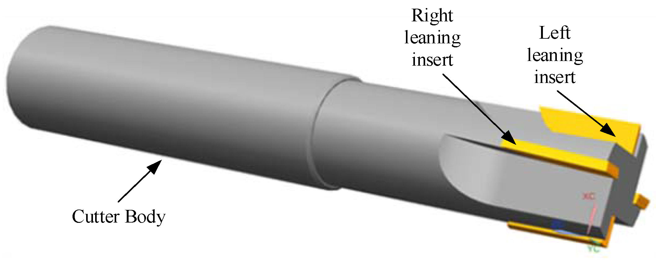
2.1. Structural Design

Helix edge is often used in the side edge of cemented carbide or coated end mills [27]. These kinds of end mill have good cutting performance, but the wear resistance is poor. Straight edge is often used in PCD cutter and it has high machining accuracy. However, the straight-edge structure will generate large cutting force in machining. To reduce machining defects, improve machined surface quality and increase the cutter’s life, this work combines the advantages of helix-edge and straight-edge structures in the design of staggered PCD end mill. The magnitude and direction of cutting force is decreased and changed by side-edge re-configuration of the staggered PCD end mill. Figure 1 shows the structure of the staggered PCD end mill.
Traditional PCD end mill has co-rotating cutting-edge inclination [28], while in the staggered PCD end mill, the directions of cutting-edge inclination of two adjacent side edges are opposite. The staggered PCD end mill is composed of a cemented carbide body and four PCD inserts with different inclination directions. Two adjacent inserts have the same inclination magnitudes and different directions, and they form a pair of cutting units. The staggered PCD end mill can be used in flank milling and end milling.

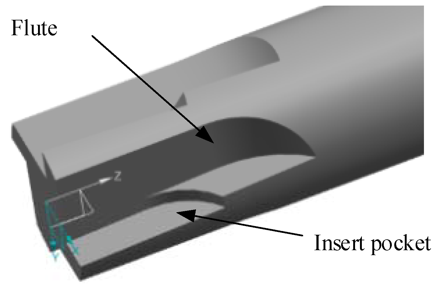
2.2. Design of Flute and Insert Pocket

The flute is designed for rapid chip removal in CFRP milling. The size and shape of flute directly affect the tool’s stiffness. A large-space flute makes for easy chip removal while decreasing the tool’s stiffness, which restricts high-speed and large-feed machining as well as improves machining efficiency. However, a small-space flute results in decreased smoothness and fast tool wear. Therefore, a large-space flute should be designed considering the tool’s stiffness. CFRP has a powdered chip and a large feed can be used, so chip removal is easy. Considering tool fabrication, the flute shown in Figure 2 is designed.
The insert pocket determines the geometric angles after insert welding, including rake angle, relief angle and cutting-edge angle. As the PCD welding process is used to fabricate the tool in this work, the tool’s geometric angles after welding and the shape of PCD composite film after cutting should be considered when designing the insert pocket. According to actual conditions, the insert pocket shown in Figure 2 is designed, which is good for positioning during welding and can reduce fabrication cost.

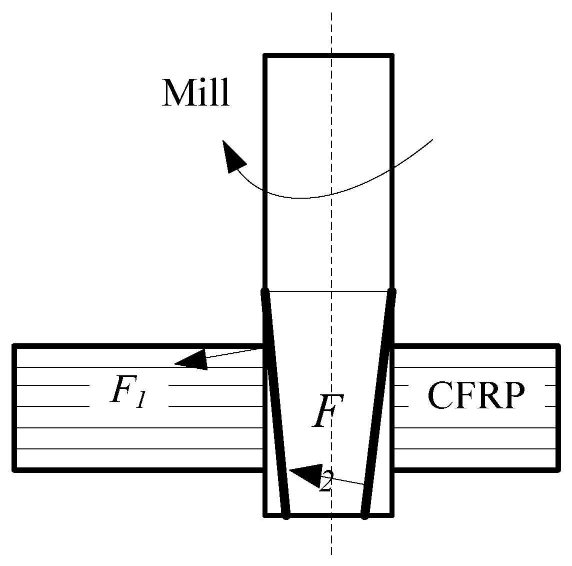
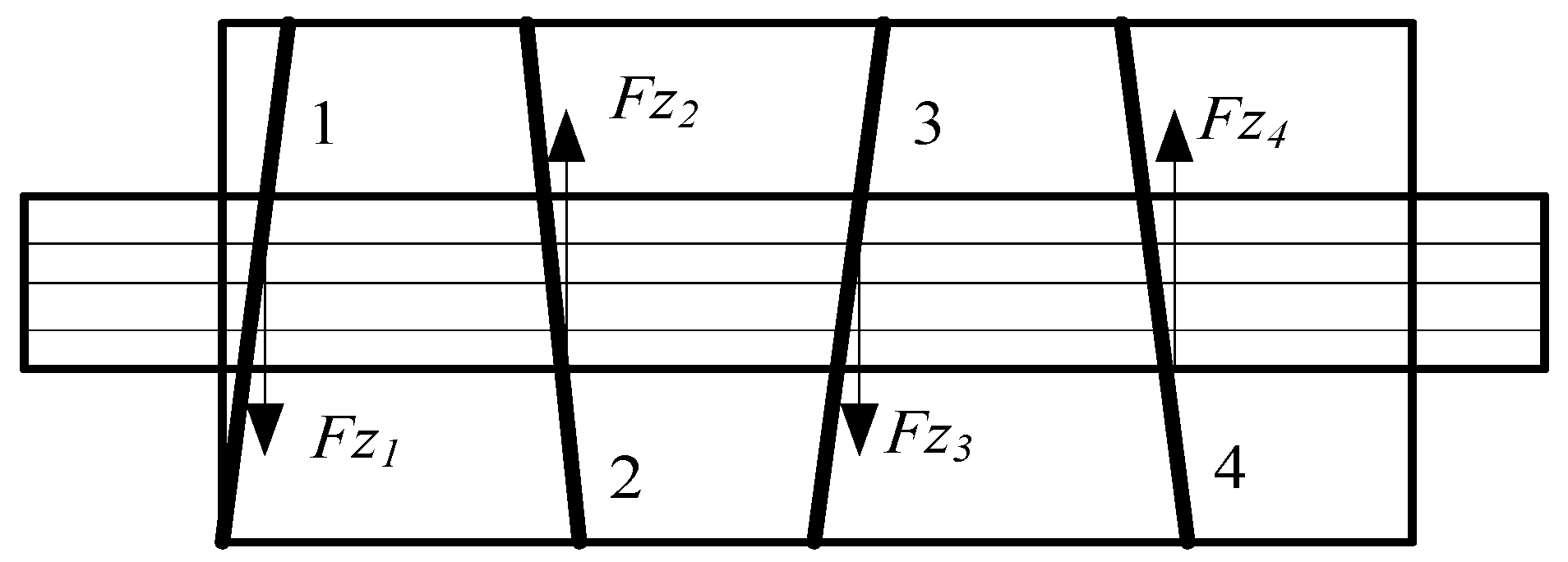
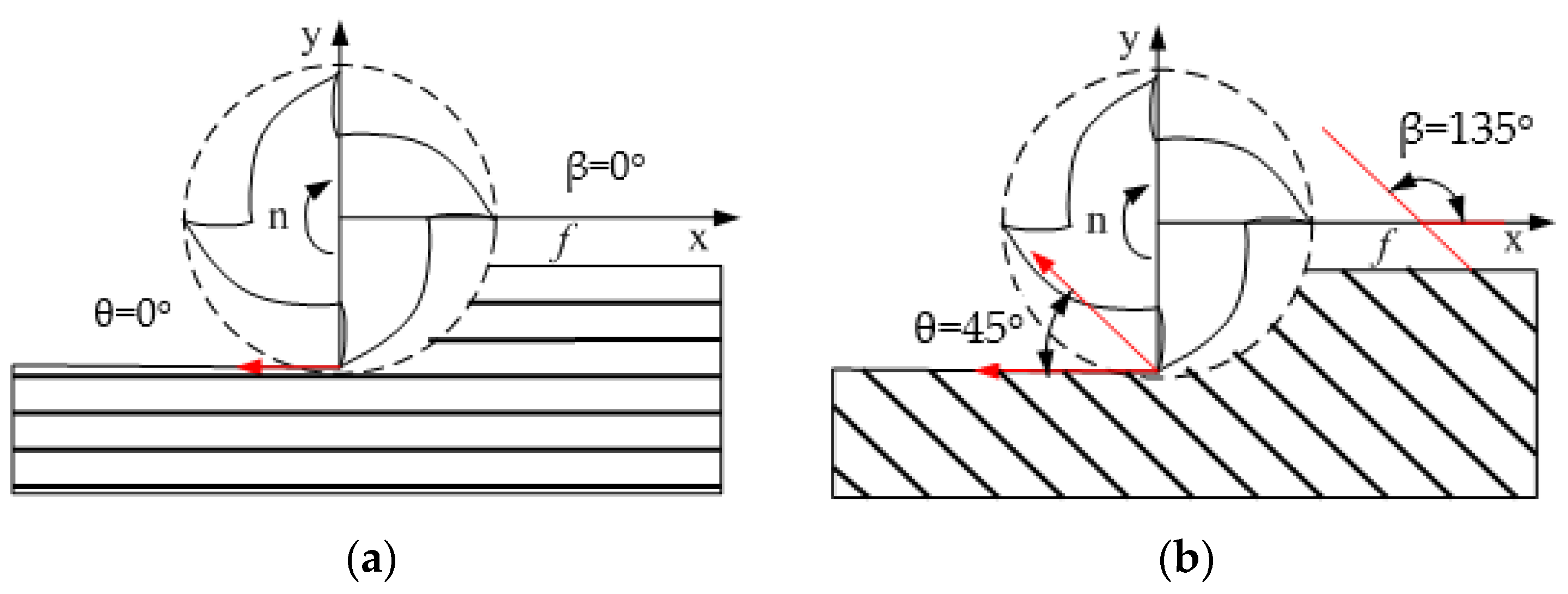
2.3. Analysis of Milling Process

The cutting-edge inclination and axial rake angle of the staggered PCD end mill are increased due to tool inclination. The radial and tangential forces of the staggered PCD end mill are less than the end mill with straight-tooth structure. Since the cutting-edge inclination directions of the staggered PCD end mill are opposite between two adjacent cutting edges, the direction of the axial force changes alternatively during milling and the changing frequency is cyclical. The cutting edge inclination is usually small due to restrictions of PCD materials and welding assembly.
In cut-in and cut-out of the end mill with straight-tooth, the contact between the cutting edge and workpiece is line contact, and the instantaneous impedance is very large. However, the contact between the cutting edge and workpiece of the staggered PCD end mill is point contact in cut-in and cut-out. Figure 3a shows the cutting of the left-leaning cutting edge, and Figure 3b shows the cutting of the right-leaning cutting edge. When cutting by the right-leaning cutting edge, the cutting edge first cuts in the point A, the cutting length involving cutting edge gradually increases and the cutting length decreases with cut-out. The left-leaning cutting edge has the same cutting process. During cutting, the cutting force increases or decreases gradually. The cutting process is more stable than the end mill with straight-tooth.

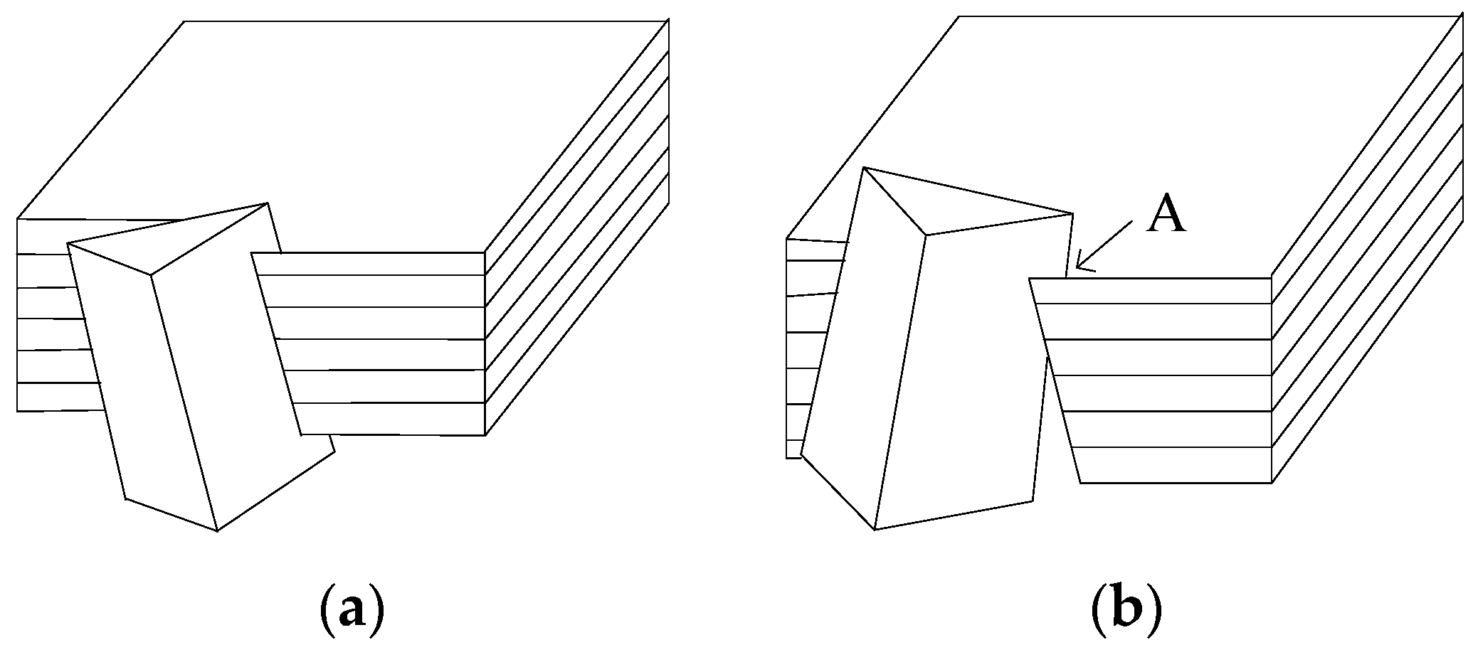
2.4. Analysis of Machining Defects

When milling CFRP laminate under the extrusion of cutting force, the fiber in the top layer will not be restrained by the outside, so it is easy to delaminate the layer. If the fiber is not cut by the tool in time, it will remain in the edge of the workpiece surface and form burr defects. If the burr is caught in the cutting area of the tool and forcibly pulled off, a tearing defect will be formed. Milling burrs and tears often appear in the surface of the fiber layer. In the machining process, a combination of cutting, shearing and fracture along the fiber/matrix interface will be observed [29,30,31].
Taking the upper surface of the workpiece, for example, as shown in Figure 4 and Figure 5, when cutting edge 1 of the staggered PCD end mill is involved in milling, the upper surface is subjected to downward axial force, and the fiber layer near the upper surface can be cut without delamination due to the support of the CFRP sheet. When cutting edge 2 is involved in milling, the upper surface is subjected to upward milling force and the fiber layer near the upper surface layer is given to local cracking owing to loss of external support, but the milling range is small and the resulting defects do not affect the cutting performance. Cutting edge 3 is involved in milling in the same way as cutting edge 1 and it generates a downward cutting force and cuts the burr generated by cutting edge 2. In high-speed milling, the left-right alternative cutting edges work like scissors in the cutting process, and good surface quality can be obtained even in high-speed and large-feed conditions.

2.5. Material of the Staggered PCD End Mill

High cutting speed of CFRP requires high strength and high stiffness [32,33]. Therefore cemented carbide is more suitable and this work selects the cemented carbide K40UF as the tool body material.
Medium grain (6.8 μm) PCD tool has good wear resistance and processing adaptability. The PCD composite film COMPAX1300P with moderate grain size is suitable for CFRP milling due to its high stiffness, high strength and wear resistance. Therefore, the PCD composite sheet COMPAX1300P is used in this work.

2.6. Structural Parameters of the Staggered PCD End Mill

Tool fracture easily occurs when cutting with large-rake-angle PCD tools, due to the high strength and hardness of CFRP, so a smaller rake angle should be used. Considering the conditions of PCD welding and grinding, the rake angle γ f is designed to be 3°.
If the relief angle is too small, fast tool wear will be found. If the relief angle is too large, the tool strength will be insufficient. To enhance the cutting edge and consider fiber resilience of CFRP and the impact of the feed on relief angle, the radial relief angle α f is designed to be 10° and the axial relief angle α p is designed to be 10°.
The inclination angle directly affects the magnitude of the axial force during milling. Axial milling force may result in delamination due to low binding force between CFRP layers. Considering the constraints of fabrication process, a small inclination angle is preferred. So in this work, the inclination angle is 3°.
The main structural parameters of the PCD end mill are shown in Table 1.

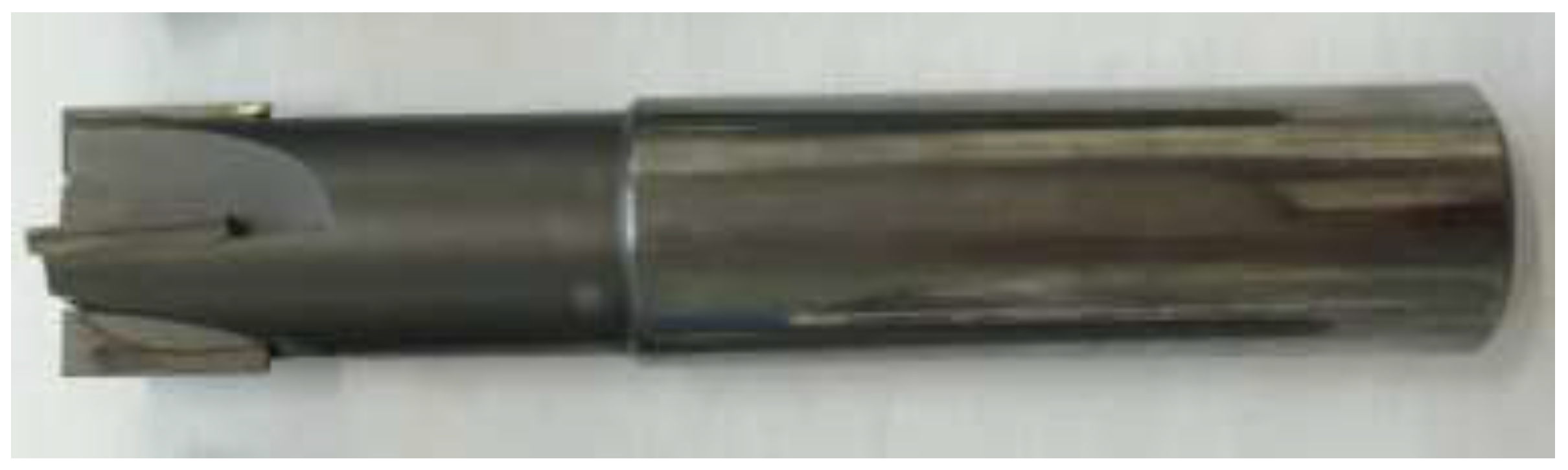
3. Fabrication of the Staggered PCD End Mill

The fabrication of the staggered PCD end mill is as follows:
(1)
Preparation and cutting of PCD composite film: according to the shape of the flute, the PCD composite film is cut into the designed shape by wire cutting.
(2)
NC machining of flute and insert pockets for the cemented carbide tool body: A 5-axis CNC grinding center is used to process the flute and insert pockets according to the design requirements.
(3)
Welding of PCD insert: Using high frequency induction brazing, silver-based solder and QJ102 silver brazing flux are used to weld the PCD inserts to the cemented carbide cutter tool body.
(4)
Grinding and passivation of the PCD cutting edges: The EWAG super-hard tool grinder is used to grind the flank of the PCD tool.
The fabricated staggered PCD end mills are shown in Figure 6.

4. Milling Experiment of CFRP

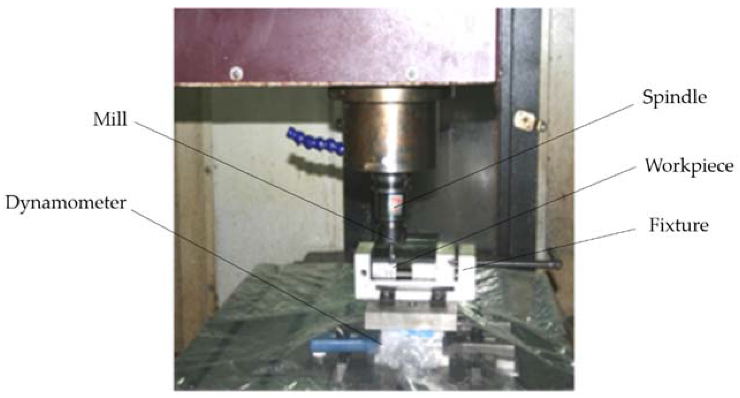
4.1. Experimental Setup

A series of milling tests of multidirectional CFRP with the staggered PCD end mill is conducted on the three-axis CNC milling machine VDL-1000E, as shown in Figure 7. The milling force measurement system is used to measure and record the milling force. The force measurement system consists of a dynamometer, charge amplifier, data acquisition system and acquisition software.
As the carbon fiber chip is powdered, a plastic sheet needs to be paved on the workpiece fixture during milling to protect the CNC machine. No coolant is used in the milling test. An industrial vacuum cleaner is used to vacuum chips near the cutter. Chips are cleaned before removing the workpiece.
Carbon fiber T700 is used as the reinforcing material of the CFRP laminate, and the base material is epoxy resin. The physical and mechanical properties of CFRP are different due to the ply methods and resin types. The main performance [23] and structural parameters of the CFRP laminate in this work are shown in Table 2 and Table 3, respectively.

4.2. Design of Experiment with the Staggered PCD End Mill

4.2.1. Design of Experiment

Design of experiment is employed in this work. Cutting speed ν , milling width a e and feed per tooth f z are selected as factors, and each factor has 4 levels. The orthogonal table of the 3 factors at 4 levels is designed, as shown in Table 4.
In the milling process, the milling force signal measured by the dynamometer is processed by software to obtain the milling force waveforms. As milling is intermittent, the mean peak cutting force is characterized as the milling force. The experimental results are shown in Table 5.

4.2.2. Range Analysis

According to the results of each experimental program, the average corresponding level of each parameter is calculated, and a range analysis of the numerical results of milling force is conducted. The range tables are shown in Table 6, Table 7 and Table 8. It is seen that feed per tooth f z and milling width a e have the greatest influence on the main cutting force F x . Feed per tooth f z has the greatest influence on the radial cutting force F y . The influence on the axial force F z in the order of principal and subordinate relationship is: feed per tooth > milling width > cutting speed.
The effects of cutting parameters on the milling forces are different. The main cutting force F x is more easily affected by the cutting parameters than the radial cutting force F y and axial force F z .

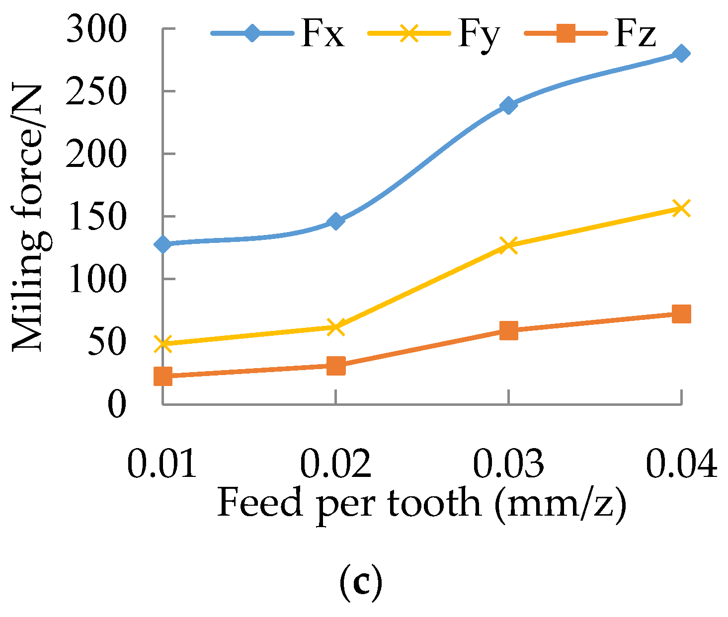
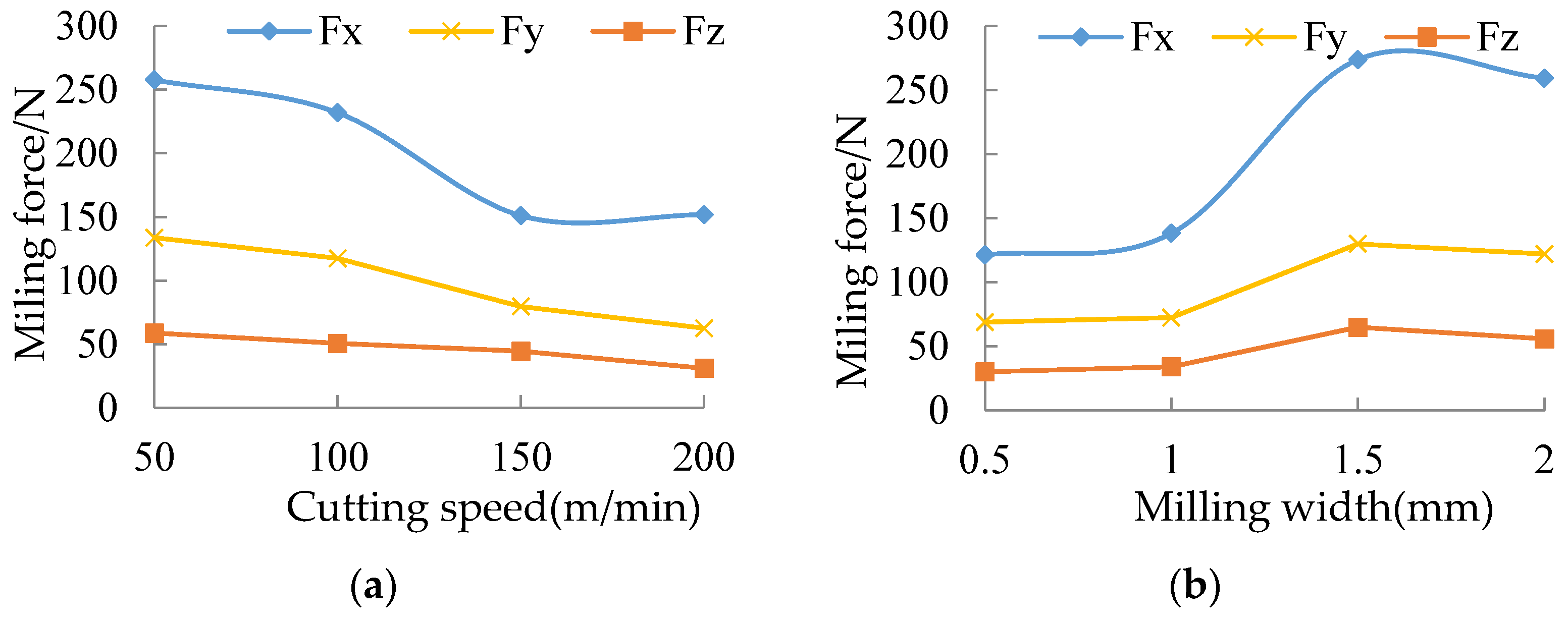
4.3. Influence of Milling Parameters on Milling Force

According to the results of the range analysis of milling force, the variation of milling forces with milling parameters is shown in Figure 8. It is seen that the milling force decreases with cutting speed, and the main cutting force varies significantly, as shown in Figure 8a. When ν = 100 150   m / min , the main cutting force decreases rapidly. When   ν = 150 200   m / min , the main cutting force only has a little increase. This is because the actual shear angle of the cutter increases with the spindle rotation speed, resulting in a decrease in shear force. As the milling temperature increases with cutting speed [25], too high a cutting speed will aggravate tool wear and the cutting force will tend to increase.
As shown in Figure 8b, the milling force has a little increase when a e = 0.5 1   mm . When a e exceeds 1 mm, the milling force increases significantly. However, when a e exceeds 1.5 mm, the milling force decreases slightly. This is because the milling material volume per tooth increases with the increase of milling width, resulting in a rapid increasing of milling force. During down milling, the milling width increases results over a distance which in turn increases the distance of each tooth participating in the milling. Therefore, the milling force tends to be stable when the milling width increases to a certain extent.
As shown in Figure 8c, the milling force increases as feed per tooth increases. Feed per tooth directly causes an increase in the milling width per tooth and the cutting area, which increases the deformation resistance and the friction force of the flank face. When f z = 0.01 0.02   mm / z , the milling force increases slowly. When f z = 0.02 0.04   mm / z , the milling force increases quickly.

5. Regression Model of Milling Force

5.1. Regression Model

In the experiment, the three parameters that affect milling force are ν ,   a e ,   and   f z . Generally, there is a certain function relationship between the cutting force and cutting parameters. The general mathematical expression between the cutting force and cutting parameters is established according to the results of orthogonal test:
F i = K i ν b 1 a e b 2 f z b 3  
where F i is generalized milling force including X, Y and Z components in three directions; K i is a coefficient determined by workpiece material and machining conditions; b 1 ,   b 2 ,   and   b 3 are exponents.
Taking the logarithm on both sides of Equation (1):
log F i = log K i + b 1 log ν + b 2 log a e + b 3 log f z
Let y j = log F i ,   x j 1 = log ν ,   x j 2 = log a e ,   x j 3 = log f z ,   b 0 = log K i
Then:
y j = b 0 + b 1 x j 1 + b 2 x j 2 + b 3 x j 3
Multiple linear regression equations can be established as:
{ y 1 = β 0 + β 1 x 11 + β 2 x 12 + β 3 x 13 + n 1 y 2 = β 0 + β 1 x 21 + β 2 x 22 + β 3 x 23 + n 2   y 16 = β 0 + β 1 x 16   1 + β 2 x 16   2 + β 3 x 16   3 + n 16
where n i is the random variable error in the experiment.
The above equations can be expressed as a matrix:
Y = Xβ + n
where
Y = [ y 1 y 2 y 3 ] ; X = [ 1 x 11 x 12 x 13 1 x 21 x 22 x 23 1 x 16   1 x 16   2 x 16   3 ] ;   β = [ β 0 β 1 β 2 β 3 ] ;   n = [ n 1 n 2 n 3 ]
Assuming that b 0 ,     b 1 ,     b 2   and   b 3 are respectively the least square estimations of β 0 ,     β 1 ,     β 2   and   β 3 , then the regression equation is:
y ^ = b 0 + b 1 x 1 + b 2 x 2 + b 3 x 3
where y ^ is the statistical variable; b 0 ,   b 1 ,   b 2   a n d   b 3 are the regression coefficients which can be calculated by:
b = ( X X ) 1 XY
Analyzing the test data by using multiple linear regression, the least square estimations of b 0 ,   b 1 ,   b 2   and   b 3 can be done, and finally the linear regression model between milling forces and milling parameters is as follows:
{ F x = 10 3.644 ν 0.280 a e 0.559 f z 0.514 F y = 10 4.199 ν 0.426 a e 0.327 f z 0.863 F z = 10 3.526 ν 0.222 a e 0.468 f z 0.909
where F x ,   F y   and   F z are the milling forces in X, Y, and Z directions, respectively.

5.2. Significance Test of Regression Model

Equation (9) is based on the cutting theory and experimental data, but the theoretical assumptions cannot reflect the significance between the model and the factors. The following is an example of the significance test of F x .
(1) Goodness of fit test of regression model
The least squares regression method is used to estimate the regression coefficients, and the goodness of fit is tested for the regression model. From Table 9, it can be seen that R 2 is greater than 0.8 in the regression model, which shows that the regression model has a good goodness of fit.
(2) Significance test of regression model (F test)
As can be seen from Table 10, the freedom degree of the sum of the residual squares is:
np − 1 = 12 (n = 16)
When significant level α = 0.05 , the critical value is:
F 0.05 ( 3 , 12 ) = 3.490
According to the F-distribution table:
F = 18.182 > F 0.05 ( 3 , 12 )
which shows the three variables of the regression model as a whole have a significant linear correlation with F x . Therefore, the regression model is significant.
(3) Significance test of regression coefficient (t test)
The significance test of regression coefficient is shown in Table 11, and:
t α / 2 ( n p 1 ) = t 0.025 ( 11 ) = 2.201
Therefore, in terms of F x , the influence of each parameter on the model is significant.
According to the process above, the significance test of regression model of the milling forces F y and F z can be done by the same way, and the results show that the regression model of the milling forces F y   and   F z is significant.

5.3. Experimental Verification

Three sets of data are selected randomly for milling test. At the same time, the milling force regression model is verified by comparing the predicted value with the test value of the milling force obtained by Equation (9). The predicted values and the test values are shown in Table 12. According to Table 12, the overall error between the test data and the theoretical results is less than 12%, so that the above-mentioned milling force model meets the requirements within the allowable error range.

6. Effects of Fiber Cutting Angle on Milling Force

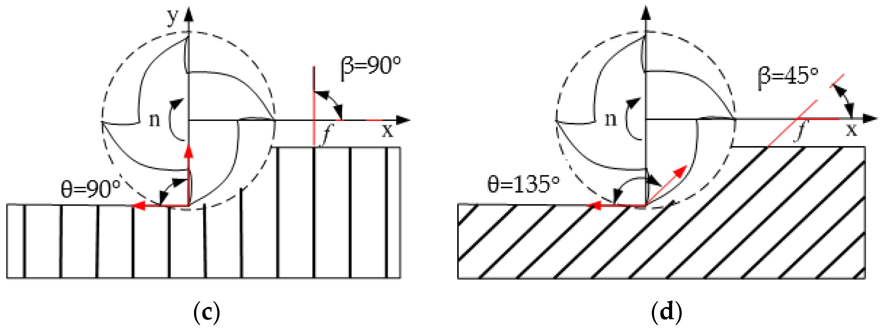
6.1. Definition of Fiber-Cutting Angle

The fiber-cutting angle of CFRP down milling can be defined according to the orthogonal cutting model of unidirectional CFRP material. In the orthogonal plane, the angle where the feed direction rotates counterclockwise to the fiber axis is defined as the milling direction angle β, and the angle between the cutting direction of the tool and the fiber axis is defined as the fiber-cutting angle θ. β and θ are used to characterize the tool path during cutting. When the milling direction angle is constant, the instantaneous fiber-cutting angle changes with tool rotation. However, the machining surface is mainly determined by the cut-out state of the tool. When the tool mills CFRP material in different milling directions during down milling, the corresponding fiber-cutting angles are different, as shown in Figure 9.

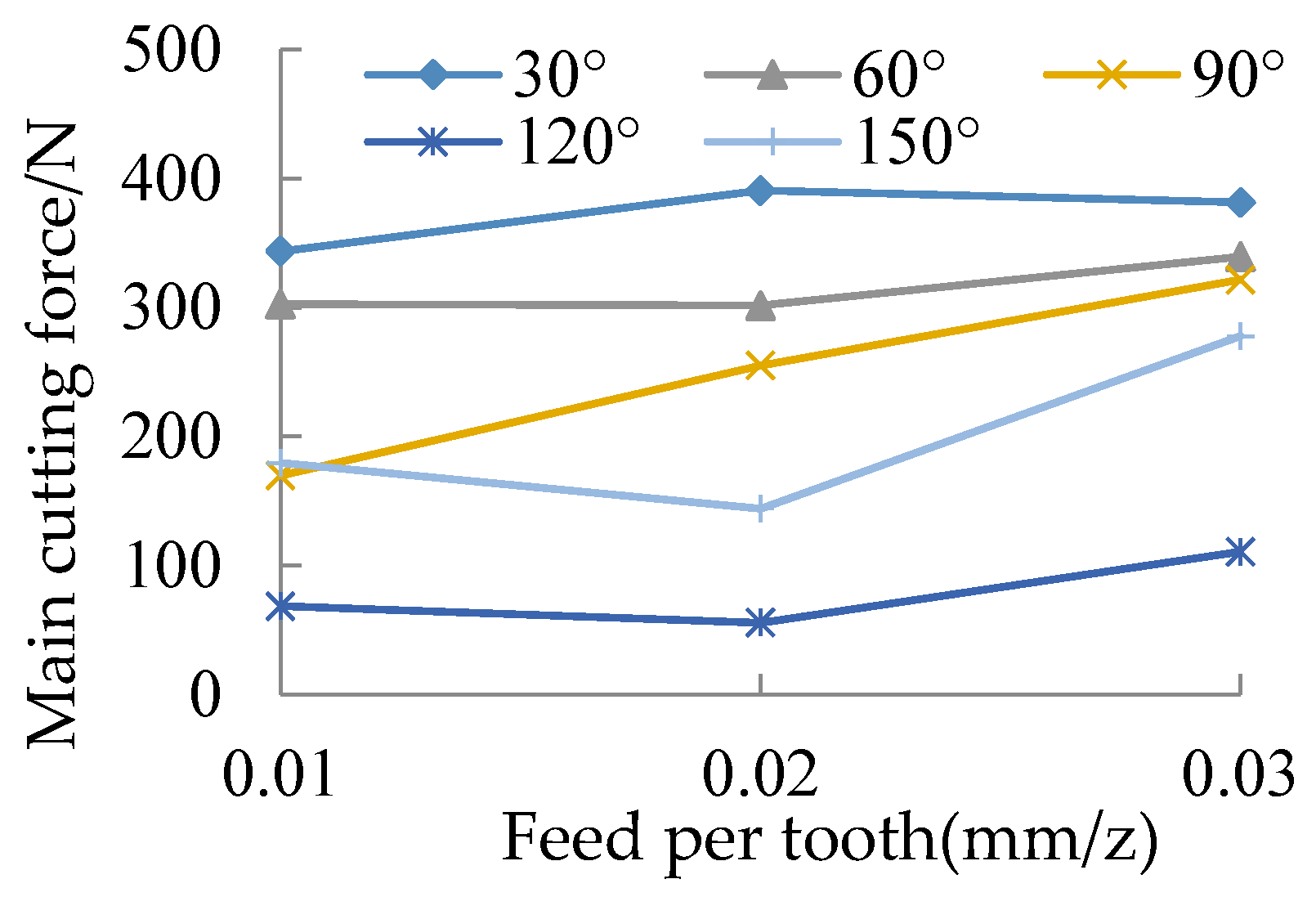
6.2. Influence of Trimming Fiber Orientation on Milling Force

The staggered PCD end mill is used in the milling of unidirectional fiber laminates. The milling parameters are: ν = 100 m / min ,   a e = 2   mm   and   f z = 0.01 ,   0.02   and   0.03   mm / z . The fiber orientation angle is 30°, 60°, 90°, 120° and 150°. The influence of fiber-cutting angle on the main cutting force is shown in Figure 10.
It is seen that the sequence of the size of the main cutting force under different fiber-cutting angles is 30° > 60° > 90° > 150° > 120°. That is, the cutting force under down milling (0° < θ < 90°) is greater than it in up milling (90° < θ < 180°). During down milling, tensile fracture of carbon fiber is found, and with the increasing of the fiber-cutting angle, tensile fracture of carbon fiber occurs more and more. During up milling, the fracture of the fiber is mainly bending fracture, and with the increase in the fiber-cutting angle, the bending fracture of the material occurs more and more. As the tensile strength of the material is higher than the bending fracture strength, in terms of cutting force, the cutting performance of up milling is better than down milling. During down milling, the cutting force increases firstly and then decreases with the increase in feed per tooth; during up milling, the cutting force decreases firstly and then increases with the increase in feed per tooth.

7. Conclusions

(1)
A staggered PCD end mill is designed for CFRP milling. The milling process of the staggered PCD end mill is analyzed, and the structural parameters of the tool are designed as the tool diameter is 12 mm, the rake angle is 3°, the rear angle is 10° and the inclination angle is 3°. The cemented carbide K40UF is selected as the tool body material.
(2)
Tool grinding and PCD composite cutting are conducted, and the welding process of the staggered PCD end mill is proposed. The tool fabrication is done using high-frequency induction brazing and cutting-edge grinding.
(3)
An empirical prediction model of milling force is established, and the significance test of the regression model is verified. It is found that the milling force decreases with the milling speed and increases with the feed per tooth and milling width.
(4)
In unidirectional CFRP milling, the main cutting force in down milling (0° < θ < 90°) is larger than that in up milling (90° < θ < 180°). During down milling, the cutting force increases first and then decreases with the increase in feed per tooth; during up milling, the cutting force decreases first and then increases with the increase in feed per tooth.

Acknowledgments

The authors would like to acknowledge the support of the International S&T Cooperation Program of China (Grant No. 2014DFA70400), the Program for New Century Excellent Talents in Heilongjiang Provincial University (Grant No. 1254-NCET-007), the Program for Harbin Science & Technology Innovation Talents (Grant No. 2015RQQXJ039), the Fundamental Research Funds for the Central Universities, and the Shanghai Natural Science Foundation (Grant No. 14ZR1443100).

Author Contributions

Guangjun Liu and Tao Chen designed the staggered PCD end mill in the work. Fei Gao conducted the milling experiment of CFRP. Xin Qian established the regression model of milling force. Hongyuan Chen analyzed the effects of fiber direction on milling force.

Conflicts of Interest

The authors declare no conflict of interest.

References

  1. Abena, A.; Soo, S.L.; Essa, K. A finite element simulation for orthogonal cutting of UD-CFRP incorporating a novel fibre-matrix interface model. Procedia CIRP 2015, 31, 539–544. [Google Scholar] [CrossRef]
  2. Slamani, M.; Gauthier, S.; Chatelain, J.F. A study of the combined effects of machining parameters on cutting force components during high speed robotic trimming of CFRPs. Measurement 2015, 59, 268–283. [Google Scholar] [CrossRef]
  3. Chen, L.; Zhang, K.; Cheng, H.; Qi, Z.; Meng, Q. A cutting force predicting model in orthogonal machining of unidirectional CFRP for entire range of fiber orientation. Int. J. Adv. Manuf. Technol. 2017, 89, 833–846. [Google Scholar] [CrossRef]
  4. Yuan, S.; Zhang, C.; Amin, M.; Fan, H.; Liu, M. Development of a cutting force prediction model based on brittle fracture for carbon fiber reinforced polymers for rotary ultrasonic drilling. Int. J. Adv. Manuf. Technol. 2015, 81, 1223–1231. [Google Scholar] [CrossRef]
  5. Khairusshima, M.K.N.; Hassan, C.H.C.; Jaharah, A.G.; Amin, A.K.M.; Idriss, A.N.M. Effect of chilled air on tool wear and workpiece quality during milling of carbon fibre-reinforced plastic. Wear 2013, 302, 1113–1123. [Google Scholar] [CrossRef]
  6. Uhlmann, E.; Schröer, N. Advances in tool grinding and development of end mills for machining of fibre reinforced plastics. Procedia CIRP 2015, 35, 38–44. [Google Scholar] [CrossRef]
  7. Tanaka, H.; Kitamura, M.; Sai, T. An Evaluation of cutting edge and machinability of inclined planetary motion milling for difficult-to-cut materials. Procedia CIRP 2015, 35, 96–100. [Google Scholar] [CrossRef]
  8. Mathivanan, N.R.; Mahesh, B.S.; Shetty, H.A. An Experimental investigation on the process parameters influencing machining forces during milling of carbon and glass fiber laminates. Measurement 2016, 91, 39–45. [Google Scholar] [CrossRef]
  9. Gao, C.; Xiao, J.; Xu, J.; Ke, Y. Factor analysis of machining parameters of fiber-reinforced polymer composites based on finite element simulation with experimental investigation. Int. J. Adv. Manuf. Technol. 2016, 83, 1113–1125. [Google Scholar] [CrossRef]
  10. Ghafarizadeh, S.; Chatelain, J.F.; Lebrun, G. Finite element analysis of surface milling of carbon fiber-reinforced composites. Int. J. Adv. Manuf. Technol. 2016, 87, 399–409. [Google Scholar] [CrossRef]
  11. Hosokawa, A.; Hirose, N.; Ueda, T.; Furumoto, T. High-quality machining of CFRP with high helix end mill. CIRP Ann. Manuf. Technol. 2014, 63, 89–92. [Google Scholar] [CrossRef]
  12. Pecat, O.; Rentsch, R.; Brinksmeier, E. Influence of milling process parameters on the surface integrity of CFRP. Procedia CIRP 2012, 1, 466–470. [Google Scholar] [CrossRef]
  13. Hintze, W.; Cordes, M.; Koerkel, G. Influence of weave structure on delamination when milling CFRP. J. Mater. Process. Technol. 2015, 216, 199–205. [Google Scholar] [CrossRef]
  14. Leone, C.; Papa, I.; Tagliaferri, F.; Lopresto, V. Investigation of CFRP laser milling using a 30 W Q-switched Yb:YAG fiber laser: Effect of process parameters on removal mechanisms and HAZ formation. Compos. A Appl. Sci. Manuf. 2013, 55, 129–142. [Google Scholar] [CrossRef]
  15. Jeyapaul, R.; Jenarthanan, M.P. Machinability study of carbon fibre reinforced polymer (CFRP) composites using design of experiment technique. Pigment Resin Technol. 2013, 43, 35–44. [Google Scholar]
  16. Maegawa, S.; Morikawa, Y.; Hayakawa, S.; Itoigawa, F.; Nalamura, T. Mechanism for changes in cutting forces for down-milling of unidirectional carbon fiber reinforced polymer laminates: Modeling and experimentation. Int. J. Mach. Tools Manuf. 2015, 100, 7–13. [Google Scholar] [CrossRef]
  17. Karpat, Y.; Polat, N. Mechanistic force modeling for milling of carbon fiber reinforced polymers with double helix tools. CIRP Ann. Manuf. Technol. 2013, 62, 95–98. [Google Scholar] [CrossRef] [Green Version]
  18. Karpat, Y.; Bahtiyar, O.; Değer, B. Mechanistic force modeling for milling of unidirectional carbon fiber reinforced polymer laminates. Int. J. Mach. Tools Manuf. 2012, 56, 79–93. [Google Scholar] [CrossRef]
  19. Wang, H.; Sun, J.; Li, J.; Li, W. Roughness modelling analysis for milling of carbon fibre reinforced polymer composites. Mater. Technology 2015, 30, A46–A50. [Google Scholar] [CrossRef]
  20. Krishnaraj, V.; Prabukarthi, A.; Ramanathan, A.; Elanghovan, N.; Kumar, M.S. Optimization of machining parameters at high speed drilling of carbon fiber reinforced plastic (CFRP) laminates. Compos. B Eng. 2012, 43, 1791–1799. [Google Scholar] [CrossRef]
  21. Chibane, H.; Morandeau, A.; Serra, R.; Bouchou, A.; Leroy, R. Optimal milling conditions for carbon/epoxy composite material using damage and vibration analysis. Int. J. Adv. Manuf. Technol. 2013, 68, 1111–1121. [Google Scholar] [CrossRef]
  22. Jenarthanan, M.P.; Jeyapaul, R. Analysis and optimisation of machinability behaviour of CFRP composites using fuzzy logic. Pigment Resin Technol. 2015, 44, 48–55. [Google Scholar] [CrossRef]
  23. Haddad, M.; Zitounea, R.; Bougherara, H.; Eyma, F.; Castanié, B. Study of trimming damages of CFRP structures in function of the machining processes and their impact on the mechanical behavior. Compos. B Eng. 2014, 57, 136–143. [Google Scholar] [CrossRef]
  24. Haddad, M.; Zitounea, R.; Eyma, F.; Castanié, B. Machinability and surface quality during high speed trimming of multi directional CFRP. Int. J. Mach. Machinability Mater. 2013, 13, 289–310. [Google Scholar] [CrossRef]
  25. Haddad, M.; Zitounea, R.; Eyma, F.; Castanié, B. Influence of machining process and machining induced surface roughness on mechanical properties of continuous fiber composites. Exp. Mech. 2015, 55, 519–528. [Google Scholar] [CrossRef]
  26. Haddad, M.; Zitounea, R.; Eyma, F.; Castanié, B. Study of the surface defects and dust generated during trimming of CFRP: Influence of tool geometry, machining parameters and cutting speed range. Compos. A Appl. Sci. Manuf. 2014, 66, 142–154. [Google Scholar] [CrossRef]
  27. Çolak, O.; Sunar, T. Cutting Forces and 3D surface analysis of CFRP milling with PCD cutting tools. Procedia CIRP 2016, 45, 75–78. [Google Scholar] [CrossRef]
  28. Maegawa, S.; Hayakawa, S.; Itoigawa, F.; Nakamura, T. Development of novel tool for cutting of carbon-fiber-reinforced plastics (Positive use of abrasive wear at tool edge for reduction in cutting force). Mech. Eng. J. 2015, 2, 15-00295. [Google Scholar] [CrossRef]
  29. Wang, D.H.; Ramulu, M.; Arola, D. Orthogonal cutting mechanisms of graphite/epoxy composite. Part I: Unidirectional laminate. Int. J. Mach. Tools Manuf. 1995, 35, 1623–1638. [Google Scholar] [CrossRef]
  30. Wern, C.W.; Ramulu, M.; Shukla, A. Investigation of stresses in he orthogonal cutting of fiber-reinforced plastics. Exp. Mech. 1996, 36, 33–41. [Google Scholar] [CrossRef]
  31. Zitoune, R.; Collombet, F.; Lachaud, F.; Piquet, R.; Pasquet, P. Experiment–calculation comparison of the cutting conditions representative of the long fiber composite drilling phase. Compos. Sci. Technol. 2005, 65, 455–466. [Google Scholar] [CrossRef]
  32. Yashiro, T.; Ogawa, T.; Sasahara, H. Temperature measurement of cutting tool and machined surface layer in milling of CFRP. Int. J. Mach. Tools Manuf. 2013, 70, 63–69. [Google Scholar] [CrossRef]
  33. Senthilkumar, M.; Prabukarthi, A.; Krishnaraj, V. Study on tool wear and chip formation during drilling carbon fiber reinforced polymer (CFRP)/titanium alloy (Ti6Al4 V) stacks. Procedia Eng. 2013, 64, 582–592. [Google Scholar] [CrossRef]
Figure 1. Structure of the staggered PCD end mill.
Applsci 07 00245 g001
Figure 2. Flute and insert pocket of the staggered PCD end mill.
Applsci 07 00245 g002
Figure 3. Analysis of milling process: (a) Cutting by left-leaning cutting edge; (b) Cutting by right-leaning cutting edge.
Applsci 07 00245 g003
Figure 4. Force analysis of the staggered PCD end mill.
Applsci 07 00245 g004
Figure 5. Unfolding axial force analysis of cutting edges of the staggered PCD end mill.
Applsci 07 00245 g005
Figure 6. The staggered PCD end mill.
Applsci 07 00245 g006
Figure 7. Experimental setup.
Applsci 07 00245 g007
Figure 8. Milling parameters versus milling forces: (a) Cutting speed versus cutting forces; (b) Milling width versus mil forces; (c) Feed per tooth versus milling forces.
Applsci 07 00245 g008aApplsci 07 00245 g008b
Figure 9. Fiber cutting direction in milling: (a) θ = 0°; (b) θ = 45°; (c) θ = 90°; (d) θ = 135°.
Applsci 07 00245 g009aApplsci 07 00245 g009b
Figure 10. Influence fiber-cutting angle on the main cutting force.
Applsci 07 00245 g010
Table 1. Structural parameters of the PCD end mill.
Rake Angle γ f / γ p Relief Angle α f / α p Inclination AngleTool LengthTool DiameterEdge Radius
3°/3°10°/10°Staggered 3°70 mm12 mm10 μm
Table 2. Mechanical properties of the multidirectional carbon fiber composite laminate.
Filament CountFilament RadiusLongitudinal Young ModulusTransversal Young ModulusShear ModulusElongationDensity
12,0007 µm142 GPa8.4 GPa3.8 GPa2.11%1.8 g/cm3
Table 3. Structural parameters of the multidirectional carbon fiber composite laminate.
Ply OrientationsVolume Ratio of Carbon FiberReinforcing MaterialMatrix MaterialSize (mm)
0°/45°/90°/135°60% ± 5%T700AG-80 epoxy200 × 110 × 5
Table 4. Design of experiment.
LevelCutting Speed v (m/min)Milling Width a e (mm)Feed Peer Tooth f z (mm/z)
1500.50.01
210010.02
31501.50.03
420020.04
Table 5. Results of the milling test.
No. v (m/min) a e (mm) f z (mm/z) F x (N) F y (N) F z (N)
1500.50.0193.4041.2515.08
25010.02137.9082.5030.16
3501.50.03365.60171.1589.70
45020.04434.00239.8599.97
51000.50.02117.2051.3024.57
610010.01112.3043.0514.30
71001.50.04394.30217.9592.04
810020.03304.00157.5071.37
91500.50.03119.6096.1541.21
1015010.04137.3081.4557.98
111501.50.01176.4079.6543.68
1215020.02170.9061.3534.97
132000.50.04155.0087.0039.65
1420010.03165.4082.5033.83
152001.50.02158.7051.3034.06
1620020.01128.2029.2516.90
Table 6. Range table of F x (N).
No.A Cutting Speed v B Milling Width a e C Feed per Tooth f z
1257.73121.30127.58
2231.95138.23146.18
3151.05273.75238.65
4151.83259.28280.15
R(Max. − Min.)106.68152.45152.58
Rank of primary-secondaryC, B, A
Table 7. Range table of F y (N).
No.A Cutting Speed v B Milling Width a e C Feed per Tooth f z
1133.6968.9348.30
2117.4572.3861.61
379.65130.01126.83
462.51121.99156.56
R(Max. − Min.)71.1861.09108.26
Rank of primary-secondaryC, A, B
Table 8. Range table of F z (N).
No.A Cutting Speed v B Milling Width a e C Feed per Tooth f z
158.7330.1322.49
250.5734.0730.94
344.4664.8759.03
431.1155.8072.41
R(Max. − Min.)27.6234.7449.92
Rank of primary-secondaryC, B, A
Table 9. Goodness of fit for regression model of milling force.
Correlation Coefficient R R 2 Adjustment R 2 Standard Error
0.9050.8200.7760.099
Table 10. Regression variance of F x .
Variance SourceDegree of FreedomSum of Squares (SS)Mean Square (MS)FSignificance
Regression30.5360.17918.1820.000
Residual120.1180.010
Sum150.654
Table 11. Significance test of regression coefficient.
Coefficien tb1b2b3Significance of Regression Coefficient
| v | | a e | | f z |
t2.5515.1014.692 b 2 > b 3 > b 1 > 2.201
Table 12. Test of regression model for milling force.
Experiment No. 1Experiment No. 2Experiment No. 3
v (m/min)75125175
a e (mm)0.751.251.75
f z (mm/z)0.0150.0250.035
Milling force (N) F x F y F z F x F y F z F x F y F z
Experimental (N)119.8759.4522.26185.1284.9339.61231.73110.2659.36
Predicted (N)129.3261.024.74193.990.1243.62253.2116.5465.82
Error (%)7.882.6111.124.746.1110.129.265.6910.88

