Article

Surface Quality of Staggered PCD End Mill in Milling of Carbon Fiber Reinforced Plastics

1
School of Mechanical Engineering, Tongji University, Shanghai 201804, China
2
School of Mechanical and Power Engineering, Harbin University of Science and Technology, Harbin 150080, China
*
Author to whom correspondence should be addressed.
Appl. Sci. 2017, 7(2), 199; https://doi.org/10.3390/app7020199
Submission received: 14 January 2017 / Revised: 4 February 2017 / Accepted: 10 February 2017 / Published: 17 February 2017

Abstract

:
Machined surface quality determines the reliability, wear resistance and service life of carbon fiber reinforced plastic (CFRP) workpieces. In this work, the formation mechanism of the surface topography and the machining defects of CFRPs are proposed, and the influence of milling parameters and fiber cutting angles on the surface quality of CFRPs is obtained, which can provide a reference for extended tool life and good surface quality. Trimming and slot milling tests of unidirectional CFRP laminates are performed. The surface roughness of the machined surface is measured, and the influence of milling parameters on the surface roughness is analyzed. A regression model for the surface roughness of CFRP milling is established. A significance test of the regression model is conducted. The machined surface topography of milling CFRP unidirectional laminates with different fiber orientations is analyzed, and the effect of fiber cutting angle on the surface topography of the machined surface is presented by using a digital super depth-of-field microscope and scanning electron microscope (SEM). To study the influence of fiber cutting angle on machining defects, the machined topography under different fiber orientations is analyzed. The slot milling defects and their formation mechanism under different fiber cutting angles are investigated.

1. Introduction

Carbon fiber reinforced plastics (CFRPs) are being extensively used in various fields due to their excellent mechanical properties [1,2]. As a difficult-to-cut material, machining of CFRP has attracted increasing attention [3,4,5]. Due to various machining defects of CFRPs, the machined surface quality of these materials is difficult to control [6], which makes CFRPs difficult to cut. Machined surface quality determines the reliability, wear resistance and service life of CFRP workpieces. The machined surface quality is affected by cutting parameters, cutting tools and cutting angles [7].
Milling is a basic machining operation of CFRPs [8]. Surface quality and machining defects play an important role in CFRP milling [9,10,11]. CFRPs are made of carbon fiber layers, and the interlaminar strength is lower than that of the inner layer. When the component force between layers is larger than the interfacial bonding strength, delamination will occur in milling. Meanwhile, the surface fiber can easily be pulled, causing burrs and tears. The main machining defects in the CFRP milling process include surface fiber burrs, surface fiber tears, and interlayer delamination [12,13]:
(1)
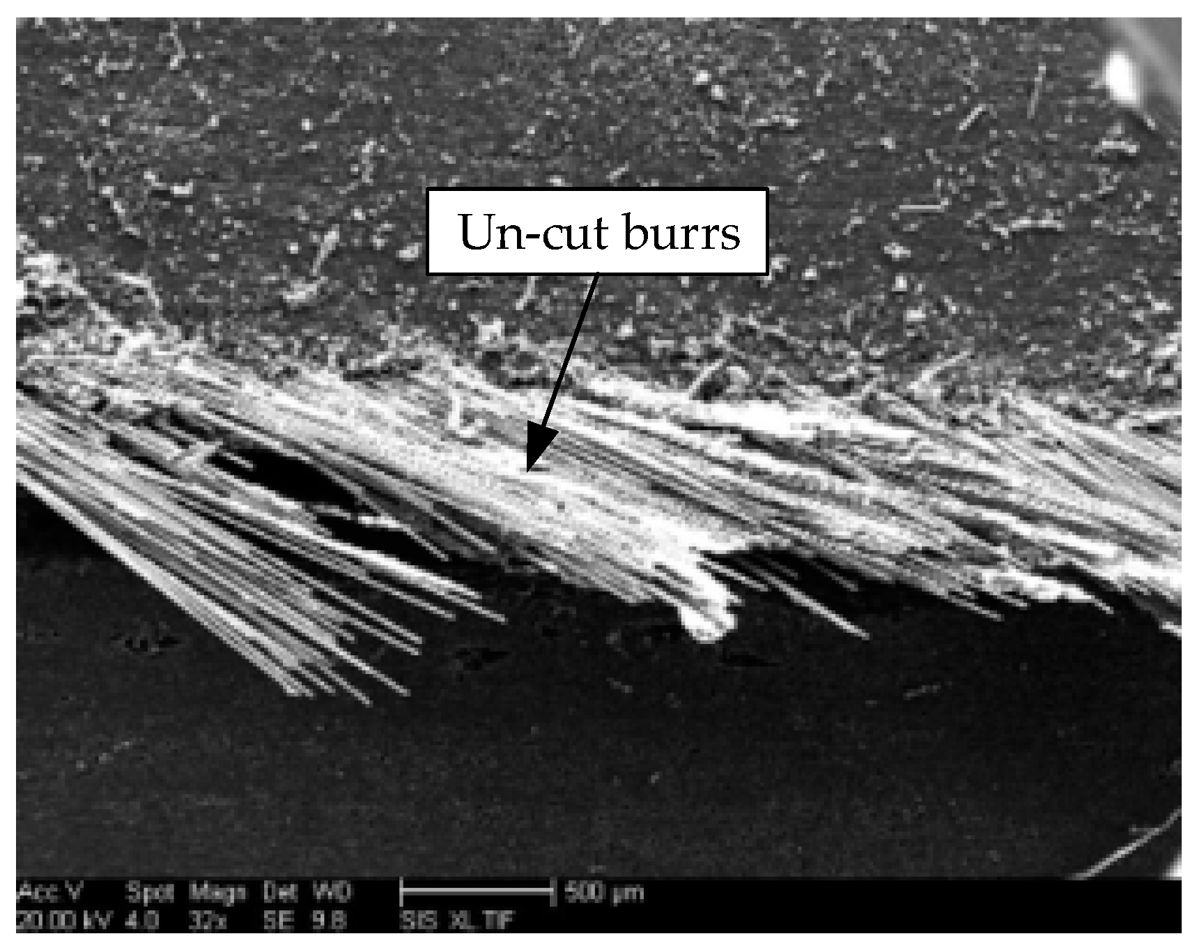
Surface fiber burr: In the milling process, the surface carbon fibers will be affected by the axial cutting force outward from the surface [14]. When the axial force is greater than the interlayer bonding force in milling, fiber debonding will occur, which means a detachment from the resin. Bending deformation occurs under a cutting force after fiber debonding. Because there is no material support outside of the surface, the un-cut carbon fiber remains on the machined surface and forms burrs. The burr direction generally follows the fiber direction.
(2)
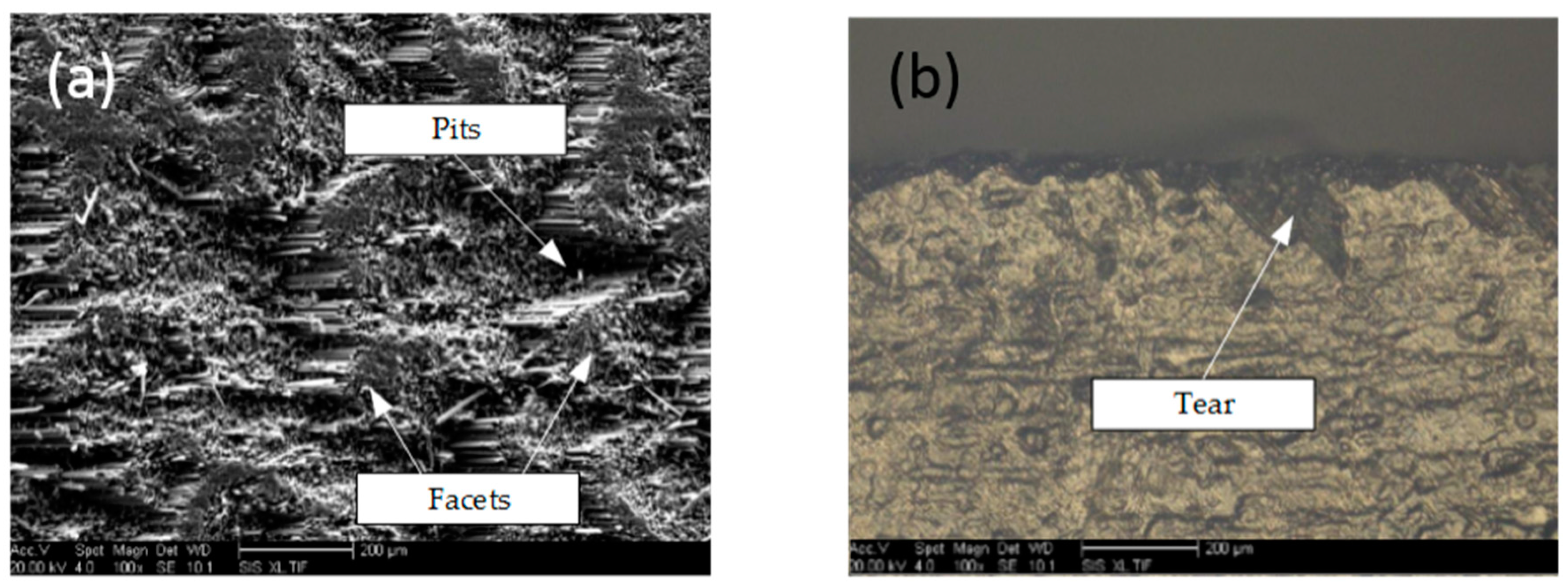
Surface fiber tear: During milling, in the inverse fiber direction, the surface carbon fiber is bent and broken by the tool, and the broken crack stretches deep into the material of the surface layer of the workpiece, and a tear defect is formed [15,16,17,18]. If the residual burr is extremely long, it can easily be twined by the cutter tooth and break the fiber. The fracture location is generally deep in the surface of the workpiece, and the tear defect is formed on the surface of the workpiece; the depth is influenced by the tear angle and cutting edge sharpness. As the axial tensile strength of the fiber is greater than the interlayer bonding strength, the fiber layer is separated from the matrix material before tensile fracture, and the tear direction is generally along the surface fiber direction. Tearing of the milling surface is generally accompanied by burr defects, and they have a similar variation tendency.
(3)
Interlayer delamination of the machined surface: When the interlayer stress exceeds the interlayer bonding strength and fiber bonding strength in the milling process, debonding will occur between the carbon fiber bundles and matrix material, accompanying the deformation of the fiber layer. The deformation of the fiber layer will gradually recover after cutting; however, the delamination defect is permanent as the matrix loses its adhesive capacity. Interlayer delamination defects may occur in any fiber layer of the milling fracture [19,20]. If they occur on the surface, there will be tear and burrs. Therefore, delamination of the surface layer is the source of the development of tear and burrs. Delamination will directly affect the material strength and fatigue resistance performance.
Milling CFRP materials is quite a complex task due to its heterogeneity [21,22]. In modern industries, components made of CFRP are increasingly used in relation to their dimensional precision as well as their surface quality [23,24]. Due to these applications, there is a great need to understand the questions associated with the machined surface quality of CFRPs [25,26]. Considering the machining defects induced by the CFRP machining process, Zenia et al. [2] proposed a finite element model for the prediction of machining defects. Çolak et al. [4] measured the 3D surface topography of a machined CFRP surface and evaluated the influences of fiber orientation on the surface quality. Gao et al. [5] built a 3D finite element model for CFRP machining and studied the influences of machining parameters on the cutting force and surface roughness. Pecat et al. [6], Rajasekaran et al. [7], Schorník et al. [12], Lissek et al. [13] and Wang et al. [14] studied the influence of cutting parameters on the surface quality of CFRPs using an experimental approach. Konneh et al. [8], Haddad et al. [9] and Voß et al. [10] investigated machining defects under various tool geometries and cutting parameters. Calzada et al. [11] developed a microstructure-based finite element model for CFRP machining to describe the fiber failure mode in the chip formation process. Hintze et al. [19] proposed a delamination model for milling unidirectional CFRPs. Maegawa et al. [27,28] studied the effects of fiber orientation direction on tool wear in the milling of CFRPs.
In this work, the machined surface quality of CFRPs is studied based on milling experiments. The focus is the formation mechanism of the surface topography and the machining defects of CFRP milling. The influence of milling parameters and fiber cutting angles on the surface quality of CFRPs is determined and analyzed.

2. Materials and Methods

A series of milling tests on multidirectional CFRPs, with a newly developed staggered PCD (Polycrystalline diamond) end mill, were conducted using the three-axis CNC milling machine VDL-1000E (Dalian R&C Machinery, Dalian, China) as shown in Figure 1.
The staggered PCD end mills used in the experiment are shown in Figure 2, and the main structural parameters of the PCD end mill are shown in Table 1.
As the carbon fiber chip is powdered, a plastic sheet is paved on the fixture during milling to protect the CNC machine. No coolant is used in the milling test. An industrial vacuum cleaner is used to vacuum chips near the mill. The chip is cleaned before removing the workpiece.
The mechanical properties and structural parameters of the CFRP laminate in this work are shown in Table 2 and Table 3, respectively.

3. Machined Surface Roughness

3.1. Experimental Procedure

Trimming and slot milling tests of unidirectional CFRP laminates were conducted. The milling parameters are shown in Table 4.
After the milling tests, the surface roughness of the machined surface was measured using a 3D profilometer to analyze the influence of the milling parameters on the surface roughness. After the experiment, the surface roughness of the machined surface was measured.

3.2. Range Analysis of Surface Roughness

The experimental results of surface roughness are shown in Table 4. Range analysis of the surface roughness results was conducted, and the range table is shown in Table 5.
It is seen that feed per tooth fz has the greatest influence on the surface roughness, and the milling width ae has the least influence on the surface roughness.

3.3. Influence of Milling Parameters on Surface Roughness

According to the range analysis of surface roughness and the experimental results, the influence of the cutting parameters on the surface roughness is shown in Figure 3.
As shown in Figure 3a, the surface roughness decreases with increasing milling speed. Because the high temperature resistance of carbon fiber is higher than that of resin material, and because the temperature will rise during high speed milling, the resin material is heated and softened. The resin coating on the machined surface increases due to the heating effect of the tool. In addition, during high speed milling, the cutting time of carbon fiber is shortened, and the fiber deformation is reduced, so the surface roughness is low.
In Figure 3b, the surface roughness increases a little with increasing milling width. In Figure 3c, with the increase in feed per tooth, the surface roughness increases. When the feed per tooth increases, the amount of fiber cut by the mill in each tooth increases, resulting in more machining defects. Meanwhile, with an increase in the feed per tooth, the springback effect of carbon fiber is enhanced, the resin coating is reduced, and the fracture of carbon fiber is increased, which result in an increase in the surface roughness.
When 0.02 mm/tooth < fz < 0.03 mm/tooth and 1 mm < ae < 1.5 mm, the surface roughness changes slightly. In this range of fz and ae, cutting speed v has the greatest influence on the surface roughness, and influences of fz and ae are relatively small. When the variations of fz and ae are small and fz is small, the surface roughness changes slightly. However, when cutting speed vc changes, the cutting temperature will change, resulting in complex surface topography.

3.4. Regression Model of Surface Roughness and Its Significance Test

In the experiment, three parameters that affect surface roughness are v, ae and fz. Generally, there is a certain functional relationship between the surface roughness and milling parameters. According to the results of the orthogonal test and the machining theory, the general mathematical expression for the relationship between the surface roughness and milling parameters can be established as:
R a = 10 1.147 v 0.227 a e 0.083 f z 0.236
In Equation (1), the correlation coefficient R is 0.897, which is calculated by the least square method. As R2 = 0.894, the regression model has a good goodness of fit. According to the significance test on the regression model, the F statistic is 34.1. According to the F-distribution table:
F > F 0.05 ( 3 , 12 ) = 3.49
Therefore, the regression model is significant.

4. Effects of Fiber Orientation on the Machined Surface

4.1. Surface Topography of the Machined Surface

4.1.1. Experimental Procedure

A down-milling experiment was conducted to observe the machined surface topography. The workpiece is CFRP unidirectional laminates with fiber direction θ = 0°, 45°, 90° and 135°. The milling parameters are v = 100 m/min, ae = 1 mm and fz = 0.02 mm/tooth.
After the experiment, the effect of fiber cutting angle on the surface topography of the machined surface was analyzed using a digital super depth-of-field microscope and scanning electron microscope (SEM).

4.1.2. Surface Topography

Figure 4a is the surface topography when θ = 45°. The carbon fiber material easily undergoes bending fracture and shear fracture, and the two kinds of fracture modes coexist. The fracture of the carbon fiber is perpendicular to the fiber axis, which is 45° relative to the machined surface, and simultaneously, the top of the fiber fracture is slightly broken under the squeezing of the tool flank face. The resin matrix of the carbon fiber has a typical shear failure, and the sheared matrix is pressed into debris adhered on the exposed fiber fracture surface, as shown in Figure 4b.
As the resin is heated and softened, it is extruded by the flank and coated on the surface fibers of the machined surface, which results in a smooth machined surface. However, when milling the CFRPs along the fiber direction, burrs on the edge of the machined surface are found, as shown in Figure 5. During milling, the surface fibers are bent by the milling force. Due to a lack of external support, the fibers are debonded under the milling force [19,20]. The stiffness of the carbon fiber is decreased, and the carbon fibers are pushed to the outside, so that they cannot be cut off by the mill over time. With the milling process, the debonded fibers are rebounded, and surface burrs are formed.
The machined surface topography is shown in Figure 6 when θ = 90°. Serious resin coating is seen in Figure 6a, and only slight fiber bareness is found, which shows a machined surface with straight-forward fiber features. Because 90° is the critical angle of the straight-forward and reversal machined surface, the carbon fiber in the cutting layer can easily undergo bending deformation. However, due to high stiffness of the carbon fiber in this direction, the bending deformation is small. After the shear fracture of the matrix, the interface is also broken by shear stress. A smooth machined surface with a small section of bare fiber appears, as shown in Figure 6b. The machined surface is further crushed under the extrusion of the tool flank, forming a fiber fracture perpendicular to the axial direction. The fracture has no obvious fracture characteristics, and the broken fibers are scattered on the top of the fracture. The matrix is squeezed by the tool flank and adheres to the top of the fracture. Meanwhile, the matrix is softened by heating and is coated on the fiber surface, as shown in Figure 6.
Figure 7 is the machined surface topography when θ = 135°. It is seen that there are bare fiber bundles on the machined surface, while many pits appear on the roots of the fiber bundles, as shown in Figure 7a. It is also observed that the lamination gaps appear in the root of fiber bundles, which is caused by the rebounding of the laminated carbon fiber. Therefore, there are pits on the machined surface, and the bottom of the pits are located at the root of the fiber bundle. The pit distribution is not continuous, and there are some cutting planes with different sizes between the pits, as shown in Figure 7a, which also appears on the machined surface topography of the multi-direction fiber laminate. For the cutting layer of the rake face, the farther away from the rake face, the lower of the deformation of the cutting layer. The large deformed cutting layer close to the rake face and small deformed cutting layer away from the rake face are simultaneously cut off during high speed machining, and pits and facets alternate on the machined surface as a sawtooth. Tear defects mainly happen at the edge of the material surface when milling CFRPs in the reverse fiber direction, as shown in Figure 7b. This is because of the surface fiber bends and fractures, and the fracture position occurs deep into the surface of the workpiece, finally forming a tear defect.
When the fiber cutting angle θ = 0°, that is, the cutting direction is parallel to the fiber direction, a surface topography of a parallel tiled fiber bundle is formed with a certain direction, as shown in Figure 8. There is almost no intact tiled fiber remaining. Tensile fracture topography along the axial direction is seen. Due to workpiece clamping, fiber ply and tool vibration, the fiber cutting angle cannot be completely zero [21,29]. The actual milling is machining with a small fiber cutting angle. When the surface springback fiber is squeezed and rubbed by the tool flank, a tensile fracture of the carbon fiber will occur on the machined surface. The resin matrix is extruded and may break to be patchily distributed in the fiber gap. The outer surface of the fiber is smooth, and only a little chip adheres on the fiber, as shown in Figure 8. This is because the position of the maximum bending stress of the layered fiber is above the cutting plane, and the position of the fractured fiber is higher than that of the machined surface.
In the milling process, the fiber on the surface is pulled out to form pits, or the fiber protrudes from the surface, and the fiber may be separated from the matrix. The machined surface appears as a complex structure. As the mechanical properties of the fiber and matrix differ considerably, their cutting mechanism is also different [30]. A rough surface is generated in CFRP milling, as shown in Figure 8, and surface roughness close to the metal cutting is difficult to obtain. Due to differences in the hardness and strength of the matrix and carbon fiber, the milling force changes abruptly when the end mill is transferred between the matrix and carbon fiber, which can result in machining defects in the transition area.

4.2. Slot Milling Defects

As presented above, it was found that the burr and tear defects mainly occurred in the upper and lower surfaces of the CFRP laminate. When the fiber cutting angle was 45°, the edges of the upper and lower surfaces of the laminate easily formed burrs. When the fiber cutting angle was 135°, the edges of the upper and lower surfaces easily formed tear defects.

4.2.1. Experimental Procedure

To study the influence of fiber cutting angle on the tear and burr defects, by using a worn mill, of which the flank wear VB = 0.08–0.1 mm, v = 100 m/min, fz = 0.02 mm/ tooth, a slot milling experiment was performed using four unidirectional CFRP laminates with fiber cutting angles of 0°, 45°, 90° and 135°.
After the experiment, the machined surface topography was observed, and the influence of the fiber cutting angle on the machining defects was analyzed.

4.2.2. Analysis of Machining Defects

In the milling process, with the rotation of the end mill, the fiber cutting angle in milling is constantly varied. The fiber cutting angle is 90°, and 0° is the demarcation point between milling along the fiber direction and reverse fiber direction. In addition, 45° and 135° are typical feature points of the two kinds of milling, so the surface topography at these intervals is very important. Figure 9 shows the fiber cutting angle when the angle between the feed direction and the fiber direction is β = 45°. The surface defect of the slot milling under different fiber cutting angles is presented in Figure 10, which shows the slot topographies of four fiber directions and the corresponding fiber cutting angles.
When β = 0°, the edge of the left half of the slot is neat and without burrs, as shown in Figure 10a, in which θ on the fiber cutting angle diagram is 180°–90°, i.e., belongs to reverse fiber cutting. However, the right half has a typical burr defect, in which θ on the fiber cutting angle diagram is 90°–0°, i.e., belongs to milling along the fiber direction. Tears and burrs are mainly located on the outer layer of the surface. They are the most common machining defects of CFRPs [29,31]. Tears are caused by milling force and extend along the fiber direction of the outer layer.
Through the analysis, when β is 45°, 90° and 35°, it is seen that burrs are more concentrated in the fiber cutting angle 0°–90° (cutting along the fiber direction), as shown in Figure 10b–d. For fiber cutting angle 90°–180° (reverse fiber milling), a smooth topography with no macroscopic defects is seen. However, through the observation of the digital super depth-of-field microscope, it can be seen that tears occur. When the tool is worn, there will be burr defects in the cutting area along the fiber direction, but in the reverse cutting area, even if the tool is badly worn, there will be no burr defects, as shown in Figure 10d. Thus, it can be concluded that in the milling process, by choosing a reasonable milling path and ensuring the surface fiber is in the inverse cutting state, a worn tool can be continuously used for milling so as to promote tool life and reduce production costs.

5. Conclusions

(1)
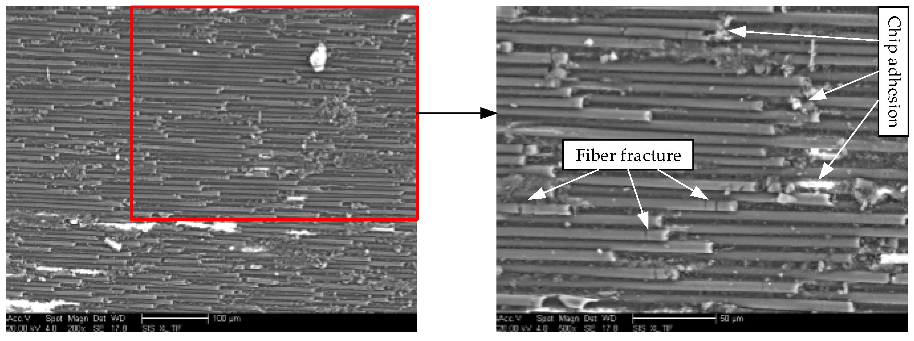
The experiment shows that the machining defects of CFRPs mainly include delamination, tearing and burrs. Tears are generally accompanied by burrs. Debonding and instability of CFRP surface material fiber is the cause of machining defects.
(2)
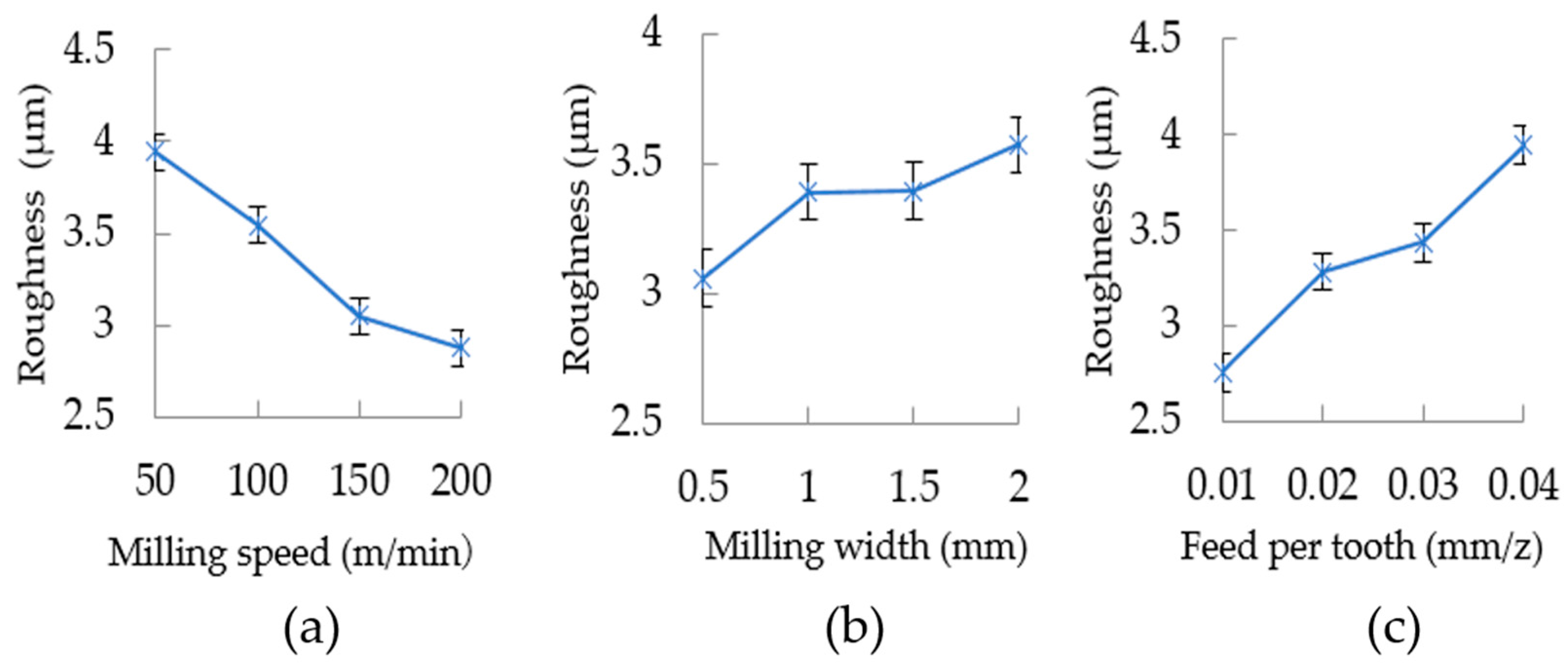
In trimming milling, the surface roughness increases with increasing feed rate and milling width and decreases with increasing milling speed. The feed rate has a greater influence on surface roughness. Increasing the milling speed and milling width can increase machining efficiency and improve machined surface quality.
(3)
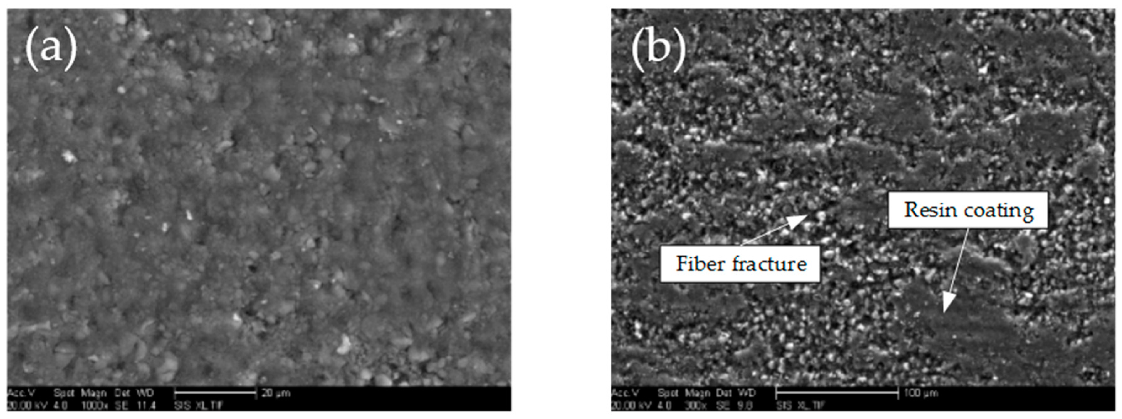
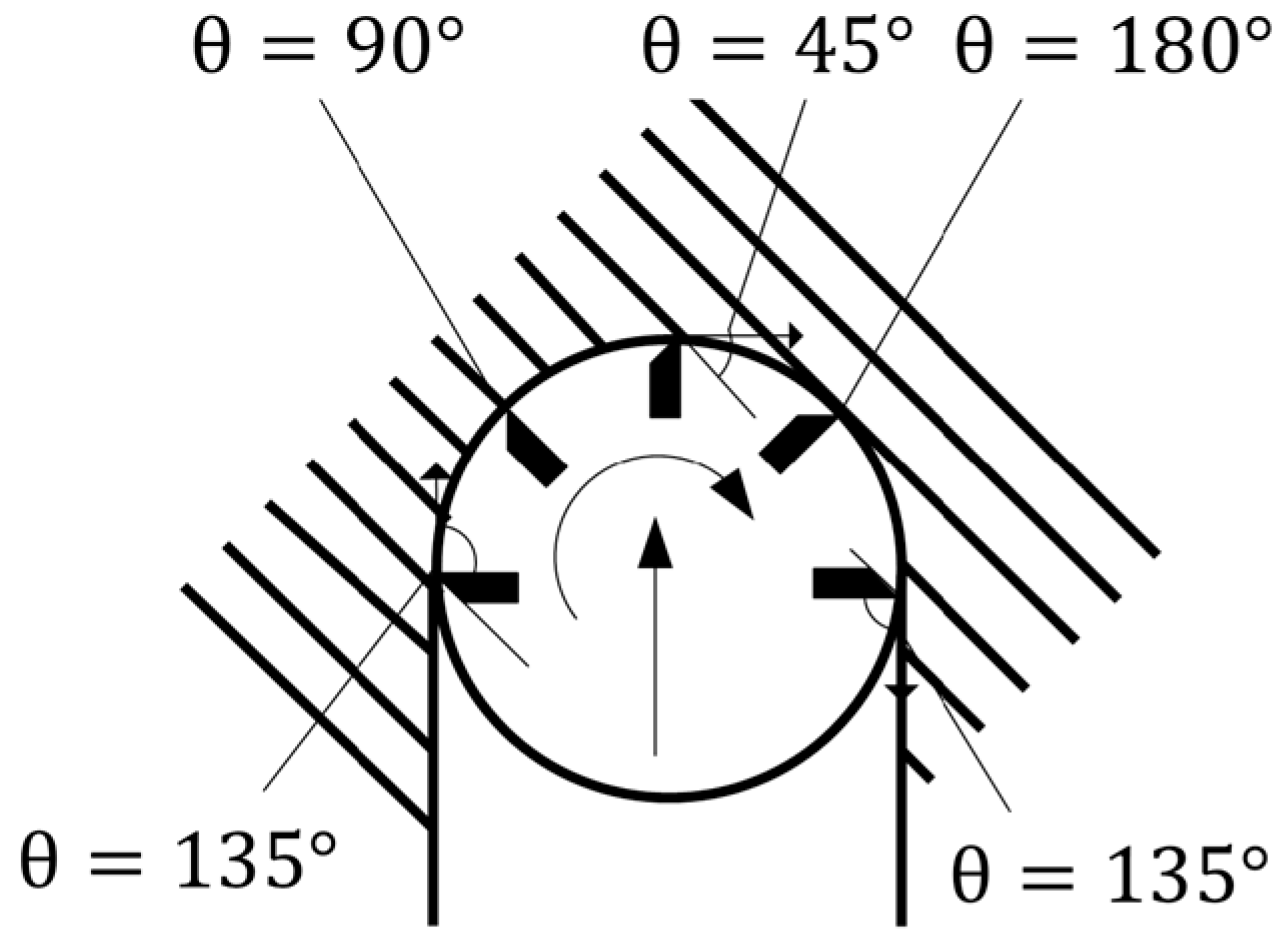
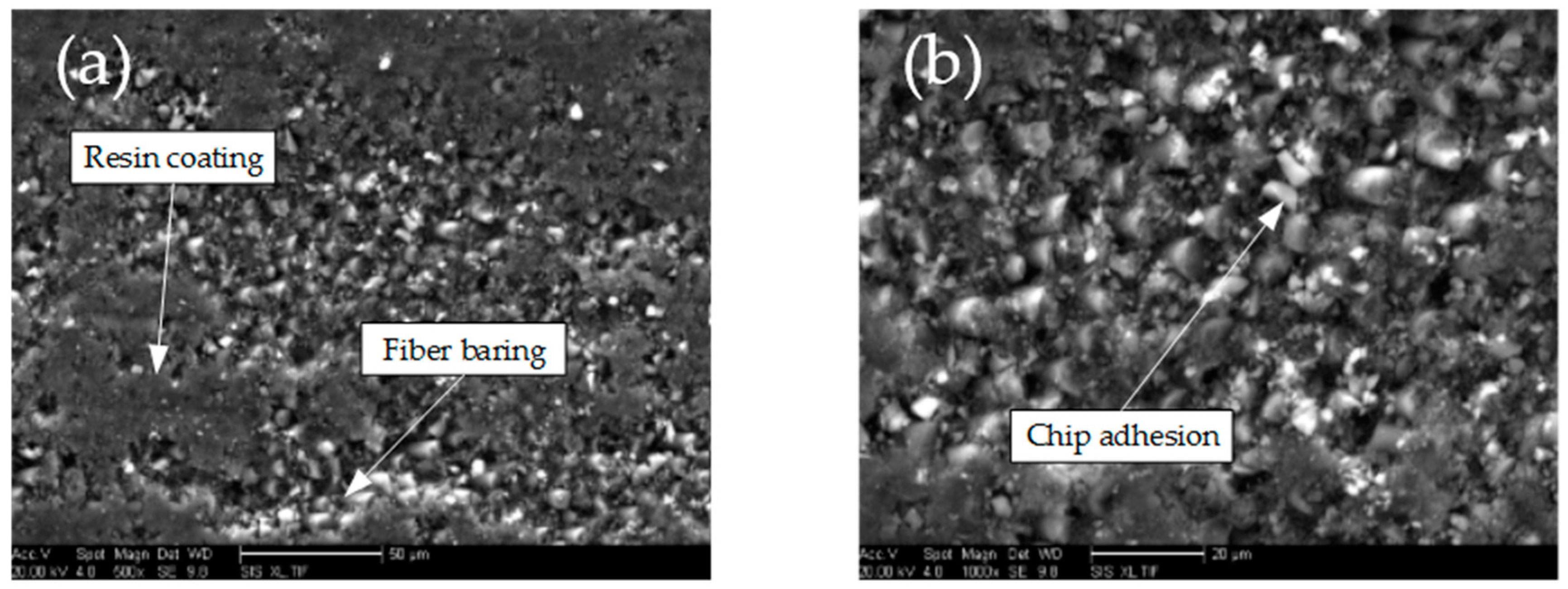
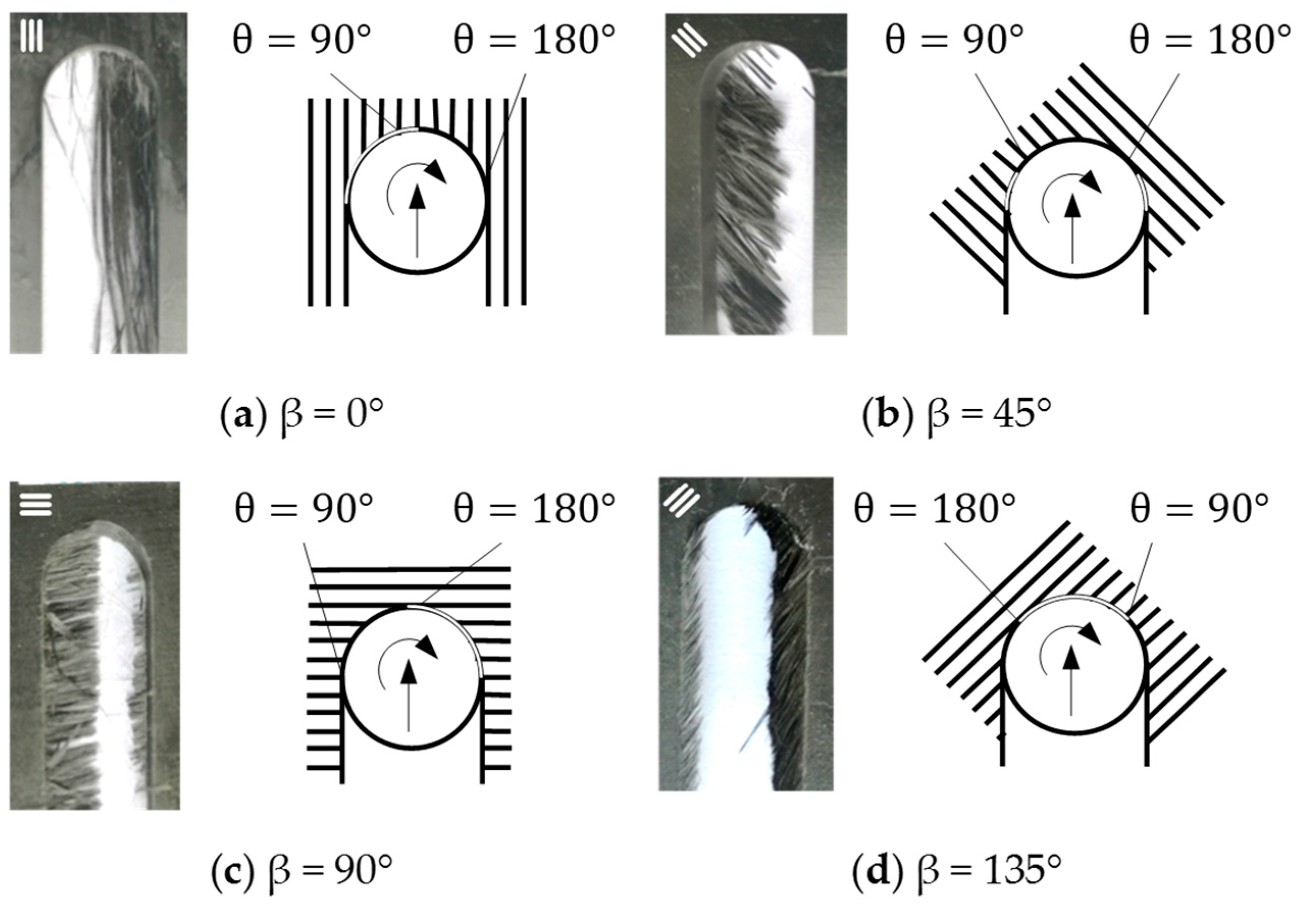
In slot milling, when cutting along the fiber direction (fiber cutting angle 0°–90°), the machining surface has severe resin coating and burrs. In reverse cutting (fiber cutting angle 90°–180°), the machined surface has serrated fractures, and tear defects occur.
(4)
In slot milling, there will be no burr defects in the reverse cutting area, even if the tool is badly worn. Therefore, by choosing a reasonable milling path and ensuring the surface fiber is in the inverse cutting state, a prolonged tool life and good surface quality can be obtained.

Acknowledgments

The authors would like to acknowledge the support of the International S&T Cooperation Program of China (Grant No. 2014DFA70400), the Program for New Century Excellent Talents in Heilongjiang Provincial University (Grant No. 1254-NCET-007), and the Fundamental Research Funds for the Central Universities.

Author Contributions

Guangjun Liu and Tao Chen designed and conducted the CFRP milling experiment. Hongyuan Chen established the regression model of surface roughness. Zhen Huang and Fei Gao analyzed the effects of fiber orientation on the machined surface.

Conflicts of Interest

The authors declare no conflict of interest.

References

  1. Slamani, M.; Gauthier, S.; Chatelain, J.F. A Study of the Combined Effects of Machining Parameters on Cutting Force Components during High speed Robotic Trimming of CFRPs. Measurement 2015, 59, 268–283. [Google Scholar] [CrossRef]
  2. Zenia, S.; Ayed, L.B.; Nouari, M.; Delamézière, A. An Elastoplastic Constitutive Damage Model to Simulate the Chip Formation Process and Workpiece Subsurface Defects when Machining CFRP Composites. Procedia CIRP 2015, 31, 100–105. [Google Scholar] [CrossRef]
  3. Voß, R.; Henerichs, M.; Kuster, F.; Wegener, K. Chip Root Analysis after Machining Carbon Fiber Reinforced Plastics (CFRP) at Different Fiber Orientations. Procedia CIRP 2014, 14, 217–222. [Google Scholar] [CrossRef]
  4. Çolak, O.; Sunar, T. Cutting Forces and 3D Surface Analysis of CFRP Milling with PCD Cutting Tools. Procedia CIRP 2016, 45, 75–78. [Google Scholar] [CrossRef]
  5. Gao, C.; Xiao, J.; Xu, J.; Ke, Y. Factor Analysis of Machining Parameters of Fiber-reinforced Polymer Composites Based on Finite Element Simulation with Experimental Investigation. Int. J. Adv. Manuf. Technol. 2016, 83, 1113–1125. [Google Scholar] [CrossRef]
  6. Pecat, O.; Rentsch, R.; Brinksmeier, E. Influence of Milling Process Parameters on the Surface Integrity of CFRP. Procedia CIRP 2012, 1, 466–470. [Google Scholar] [CrossRef]
  7. Rajasekaran, T.; Palanikumar, K.; Arunachalam, S. Investigation on the Turning Parameters for Surface Roughness Using Taguchi Analysis. Procedia Eng. 2013, 51, 781–790. [Google Scholar] [CrossRef]
  8. Konneh, M.; Izman, S.; Kassim, A.A.R. Milling Damage on Carbon Fibre Reinforced Polymer Using TiAlN Coated End Mills. J. Phys. Conf. Ser. 2015, 628, 12033–12040. [Google Scholar] [CrossRef]
  9. Haddad, M.; Zitoune, R.; Eyma, F.; Castanie, B. Study of the Surface Defects and Dust Generated during Trimming of CFRP: Influence of Tool Geometry, Machining Parameters and Cutting Speed Range. Compos. A Appl. Sci. Manuf. 2014, 66, 142–154. [Google Scholar] [CrossRef]
  10. Voß, R.; Henerichs, M.; Rupp, S.; Kuster, F.; Wegener, K. Evaluation of Bore Exit Quality for Fibre Reinforced Plastics Including Delamination and Uncut Fibres. CIRP J. Manuf. Sci. Technol. 2016, 12, 56–66. [Google Scholar] [CrossRef]
  11. Calzada, K.A.; Kapoor, S.G.; Devor, R.E.; Samuel, J.; Srivastava, A.K. Modeling and Interpretation of Fiber Orientation-based Failure Mechanisms in Machining of Carbon Fiber-reinforced Polymer Composites. J. Manuf. Process. 2012, 14, 141–149. [Google Scholar] [CrossRef]
  12. Schorník, V.; Daňa, M.; Zetková, I. The Influence of the Cutting Conditions on the Machined Surface Quality when the CFRP Is Machined. Procedia Eng. 2015, 100, 1270–1276. [Google Scholar] [CrossRef]
  13. Lissek, F.; Tegas, J.; Kaufeld, M. Damage Quantification for the Machining of CFRP: An Introduction about Characteristic Values Considering Shape and Orientation of Drilling-induced Delamination. Procedia Eng. 2016, 149, 2–16. [Google Scholar] [CrossRef]
  14. Wang, H.; Sun, J.; Li, J.; Li, W. Roughness Modelling Analysis for Milling of Carbon Fibre Reinforced Polymer Composites. Mater. Technol. 2015, 30, A46–A50. [Google Scholar] [CrossRef]
  15. Kiliçkap, E.; Yardimeden, A.; Çelik, H.Y. Investigation of Experimental Study of End Milling of CFRP Composite. Sci. Eng. Compos. Mater. 2015, 22, 89–95. [Google Scholar] [CrossRef]
  16. Geng, D.; Zhang, D.; Xu, Y.; He, F.; Liu, D.; Duan, Z. Rotary Ultrasonic Elliptical Machining for Side Milling of CFRP: Tool Performance and Surface Integrity. Ultrasonics 2015, 59, 128–137. [Google Scholar] [CrossRef] [PubMed]
  17. Yagishita, H. Experimental Research on Circular Milling of Bi-layer Composite Materials Consisting of CFRP Laminates and Titanium Alloys. Key Eng. Mater. 2014, 622, 1207–1214. [Google Scholar] [CrossRef]
  18. Shyha, I.; Soo, S.L.; Aspinwall, D.; Bradley, S. Effect of Laminate Configuration and Feed rate on Cutting Performance when Drilling Holes in Carbon Fibre Reinforced Plastic Composites. J. Mater. Process. Technol. 2010, 210, 1023–1034. [Google Scholar] [CrossRef]
  19. Hintze, W.; Hartmann, D. Modeling of Delamination during Milling of Unidirectional CFRP. Procedia CIRP 2013, 8, 444–449. [Google Scholar] [CrossRef]
  20. Hintze, W.; Cordes, M.; Koerkel, G. Influence of Weave Structure on Delamination when Milling CFRP. J. Mater. Process. Technol. 2015, 216, 199–205. [Google Scholar] [CrossRef]
  21. Davim, J.P. Machinability of Fibre-Reinforced Plastics; DE Gruyter: Berlin, Germany, 2015. [Google Scholar]
  22. Davim, J.P. Machining Composite Materials; ISTE-Wiley: London, UK, 2009. [Google Scholar]
  23. Davim, J.P.; Reis, P.; António, C.C. A Study on Milling of Glass Fiber Reinforced Plastics Manufactured by Hand-lay up Using Statistical Analysis (ANOVA). Compos. Struct. 2004, 64, 493–500. [Google Scholar] [CrossRef]
  24. Davim, J.P.; Mata, F.; Gaitonde, V.N.; Karnik, S.R. Machinability Evaluation in Unreinforced and Reinforced PEEK Composites Using Response Surface Models. J. Thermoplast. Compos. Mater. 2010, 23, 5–18. [Google Scholar] [CrossRef]
  25. Davim, J.P.; Silva, L.R.; Festas, A.; Abrão, A.M. Machinability Study on Precision Turning of PA66 Polyamide with and without Glass Fiber Reinforcing. Mater. Des. 2009, 30, 228–234. [Google Scholar] [CrossRef]
  26. Davim, J.P.; Mata, F. Physical Cutting Model of Polyetheretherketone Composites. Mater. Des. 2006, 27, 847–852. [Google Scholar] [CrossRef]
  27. Maegawa, S.; Morikawa, Y.; Hayakawa, S.; Itoigawa, F.; Nakamura, T. Mechanism for Changes in Cutting Forces for Down-milling of Unidirectional Carbon Fiber Reinforced Polymer Laminates: Modeling and Experimentation. Int. J. Mach. Tool. Manuf. 2016, 100, 7–13. [Google Scholar] [CrossRef]
  28. Maegawa, S.; Morikawa, Y.; Hayakawa, S.; Itoigawa, F.; Nakamura, T. Effects of Fiber Orientation Direction on Tool-wear Processes in Down-milling of Carbon Fiber-reinforced Plastic Laminates. Int. J. Autom. Technol. 2015, 9, 356–364. [Google Scholar]
  29. Davim, J.P.; Rubiob, J.C.; Abraob, A.M. A Novel Approach Based on Digital Image Analysis to Evaluate the Delamination Factor after Drilling Composite Laminates. Compos. Sci. Technol. 2007, 67, 1939–1945. [Google Scholar] [CrossRef]
  30. Davim, J.P.; Mata, F. Optimisation of Surface Roughness on Turning Fibre-reinforced Plastics (FRPs) with Diamond Cutting Tools. Int. J. Adv. Manuf. Technol. 2005, 26, 319–323. [Google Scholar] [CrossRef]
  31. Davim, J.P.; Reis, P. Machinability Study on Composite (Polyetheretherketone Reinforced with 30% Glass Fibre–PEEK GF 30) Using Polycrystalline Diamond (PCD) and Cemented Carbide (K20) Tools. Int. J. Adv. Manuf. Technol. 2004, 23, 412–418. [Google Scholar] [CrossRef]
Figure 1. Experimental setup.
Applsci 07 00199 g001
Figure 2. The staggered PCD (Polycrystalline diamond) end mills.
Applsci 07 00199 g002
Figure 3. Influence of milling parameters on surface roughness. (a) Ra versus v; (b) Ra versus ae; (c) Ra versus fz.
Applsci 07 00199 g003
Figure 4. Machined surface topography when θ = 45°. (a) Resin coating and fiber baring (SEM micrograph); (b) Chip adhesion (SEM micrograph).
Applsci 07 00199 g004
Figure 5. Surface burrs when θ = 45° (SEM micrograph).
Applsci 07 00199 g005
Figure 6. Machined surface topography when θ = 90°. (a) Serious resin coating (SEM micrograph); (b) Slight resin coating (SEM micrograph).
Applsci 07 00199 g006
Figure 7. Machined surface topography when θ = 135°. (a) Machined surface topography (SEM micrograph); (b) Upper surface tearing (microscope image).
Applsci 07 00199 g007
Figure 8. Machined surface topography when θ = 0° (SEM micrograph).
Applsci 07 00199 g008
Figure 9. Diagram of slot milling cutting angle.
Applsci 07 00199 g009
Figure 10. Slot milling topography of different fiber orientations. (a) β = 0°; (b) β = 45°; (c) β = 90°; (d) β = 135°.
Applsci 07 00199 g010
Table 1. Structural parameters of the staggered PCD end mill.
Rake AngleRelief AngleInclination AngleTool LengthTool Diameter
3 ° / 3 ° 10 ° / 10 ° Staggered 3 ° 70 mm12 mm
Table 2. Mechanical properties of carbon fiber T700.
Filament CountFilament RadiusLongitudinal Young’s ModulusTransversal Young’s ModulusShear ModulusElongationDensity
12,0000.5–1 μm230 GPa8.4 GPa3.8 GPa2.11%1.8 g / cm 3
Table 3. Structural parameters of the multidirectional CFRP (Carbon fiber reinforced plastics) laminate.
Ply OrientationVolume Ratio of Carbon FiberReinforcing MaterialMatrix MaterialSize (mm)
0 ° / 45 ° / 90 ° / 135 ° 60 % ± 5 % T700AG-80 epoxy200 × 110 × 5
Table 4. Orthogonal experimental results of surface roughness.
No.Cutting Speed v (m/min)Milling Width ae (mm)Feed Per Tooth fz (mm/tooth)Surface Roughness Ra (μm)
1500.50.012.97
25010.023.77
3501.50.034.21
45020.044.83
51000.50.023.26
610010.013.12
71001.50.044.21
810020.033.60
91500.50.033.00
1015010.043.73
111501.50.012.27
1215020.023.20
132000.50.043.01
1420010.032.93
152001.50.022.90
1620020.012.67
Table 5. Range table of surface roughness.
No.A—Cutting Speed v (m/min)B—Milling Width ae (mm)C—Feed Per Tooth fz (mm/tooth)
13.9423.0582.755
23.5473.3883.282
33.0503.3953.435
42.8773.5733.943
R(Max.−Min.)1.0650.5151.188
Rank of primary-secondaryC, A, B

