Article

Research on the Rational Yield Ratio of Isolation System and Its Application to the Design of Seismically Isolated Reinforced Concrete Frame-Core Tube Tall Buildings

1
Beijing Advanced Innovation Center for Future Urban Design, Beijing University of Civil Engineering and Architecture, Beijing 100044, China
2
School of Civil and Transportation Engineering, Beijing University of Civil Engineering and Architecture, Beijing 100044, China
3
School of Civil Engineering, Southeast University, Nanjing 210096, China
*
Author to whom correspondence should be addressed.
Appl. Sci. 2017, 7(11), 1191; https://doi.org/10.3390/app7111191
Submission received: 10 October 2017 / Revised: 14 November 2017 / Accepted: 15 November 2017 / Published: 19 November 2017

Abstract

:

Featured Application

A high-efficiency design method based on the rational yield ratio of isolation system is proposed and applied to the design of the seismically isolated RC frame-core tube tall buildings. The research outcome of this paper can guide the design of such buildings located in high seismic region and significantly improve the design efficiency.

Abstract

Resilience-based seismic design of reinforced concrete (RC) tall buildings has become an important trend in earthquake engineering. Seismic isolation technology is an effective and important method to improve the resiliency of RC frame-core tube tall buildings located in high seismic regions. However, the traditional design method for this type of building does not focus on the key design parameter, namely, the yield ratio of the isolation system and has therefore been proved to be highly inefficient. To address these issues, the rational yield ratio of isolation system for such buildings is investigated based on 28 carefully designed cases, considering the influences of total heights, yield ratios and seismically isolated schemes. The rational range of the yield ratio is recommended to be 2-3%. Based on this, a high-efficiency design method is proposed for seismically isolated RC frame-core tube tall buildings. Subsequently, a seismically isolated RC frame-core tube tall building with a height of 84.1 m is designed using the proposed design method. The rationality, reliability and efficiency of the proposed method are validated. The research outcome can serve as a reference for further development of the seismic design method for seismically isolated RC frame-core tube tall buildings.

1. Introduction

In recent years, studies on the resilience-based seismic design of next-generation cities have attracted much attention in earthquake engineering [1,2,3,4]. To achieve a seismically resilient city, it is essential to improve the seismic resilience of important buildings that can highly affect the normal operation of the city, such as the government buildings, hospitals and telecommunications buildings, which are usually constructed using reinforced concrete (RC) tall structure. For RC tall buildings located in high seismic regions, it is difficult to achieve a seismic resilient structure through traditional seismic design [5]. It is well acknowledged that the seismic isolation technology can significantly reduce or even eliminate the damage of structural and nonstructural components [6,7,8,9,10,11,12,13,14,15,16], thus enabling the buildings to achieve a resilient performance after an earthquake. Hence, the seismic isolation technology is considered an effective and important method to realize resilient RC tall buildings located in high seismic regions. The seismic design of one type of typical seismically isolated RC tall buildings, namely, the RC frame-core tube tall building, is studied here.
In comparison with the seismic design of seismically isolated multi-story buildings, it is somewhat difficult to design seismically isolated tall buildings, which satisfy all the requirements specified in the Chinese Code for seismic design of buildings (GB50011-2010) [17], including the efficiency of isolation system, the maximum bearing displacement (MBD) and the maximum tensile and compressive stresses of isolators. This is due to the characteristics of the RC frame-core tall buildings, including long fundamental period, large weight and significant overturning effect [7,9,18]. Various problems may be encountered during the design of such isolated tall building, especially in the design of the isolation system. Specifically, some of the main problems are as follows: (1) Numerous parameters are required to be determined. The selection of the isolators, including the number, size and type (which includes the lead rubber bearing (LRB) and the natural rubber bearing (NRB)) of the isolators, are extremely complicated. In addition, nonlinear fluid viscous dampers (NFVDs) may be required to control the large MBD, which is usually observed in the isolation system. (2) Design experience and comprehensive investigations on such buildings are less reported than those on the multi-story buildings. It is worth mentioning here that a step-by-step iterative design method based on a refined finite element (FE) model is usually adopted for such buildings, leading to an overwhelming workload to create such model and implement the time history analysis [9]. The traditional design method of the isolated tall buildings is conclusively considered undesirable and inefficient for the RC frame-core tube tall buildings.
In light of the issues discussed above, this study aims to (1) identify and propose a rational range of the critical design parameter for the isolation system of the RC frame-core tube buildings, (2) develop a high-efficiency design method based on such range and (3) validate the rationality and reliability of this method. The yield ratio of the isolation system (referred to as the “yield ratio” hereafter), Qy/W, is defined as the ratio of the total yield force of the LRBs (Qy) to the total seismic weight of the structure (W) [19,20,21,22,23]. Previous research has indicated that the yield ratio is a critical design parameter, which significantly affects the efficiency of the isolation system and the seismic performance of the entire building [19,20,21,22,23]. It is also notable that yield ratio is directly related to the quantity of the LRB isolators. Hence, a rational range of yield ratio can be theoretically used to guide the design of an isolation system. Various investigations on the rational value of the yield ratio have been conducted for multi-story buildings. Pourzeynali et al. [24] studied the optimal values of the parameters of the base isolation system. Shen et al. [25] investigated the influence of the yield ratio on the seismic responses of a multi-story isolated structure and found that there existed a rational range for the yield ratio. Wang et al. [26], Li [21], Providakis et al. [20] and Mollaioli et al. [22] also investigated the rational range of the yield ratio.
These investigations indicate that the rational range of the yield ratio is highly related to the seismic responses of structures. It is notable that the total height and the seismically isolated scheme also have a certain extent of influence on the seismic response of such buildings and therefore, affect the rational range of the yield ratio. However, investigations on the rational range of the yield ratio with consideration of such factors, as well as the high-efficiency design method based on this, have been rarely reported for seismically isolated RC frame-core tube tall buildings.
As described above, based on two real engineering practices (seismically isolated RC frame-core tube buildings) with different heights located in high seismic regions, 28 study cases with different yield ratios and seismically isolated schemes are designed. Subsequently, the influence of the yield ratio on the efficiency of the isolation system and the MBD are investigated. A rational range of the yield ratio is recommended and is used to propose a high-efficiency design method for the isolated tall building. Subsequently, a seismically isolated RC frame-core tube building with a height of 84.1 m is designed using the proposed design method. The rationality, reliability and efficiency of the proposed method are validated. The research outcome can serve as a reference for further development of seismic design method for seismically isolated RC frame-core tube tall buildings.

2. Rational Range of the Yield Ratio of Isolation System

As mentioned above, the yield ratio of isolation system is a critical design parameter for the seismically isolated RC frame-core tube tall buildings. To obtain a rational value for this ratio, a number of rational and comprehensive study cases are required. Specifically, (1) the cases based on real engineering practices, which are located in high seismic region with different heights, are preferred; (2) different seismically isolated schemes, which are determined according to real architectural design requirements, should be considered; (3) a number of yield ratios of isolation system, covering a sufficiently large range, are required for such investigation. To achieve these, two carefully designed real engineering practices with different heights are selected as the prototype buildings. Based on the prototype buildings, the study cases accounting for different seismically isolated schemes and yield ratios of isolation system are designed to investigate the rational yield ratio of isolation system.

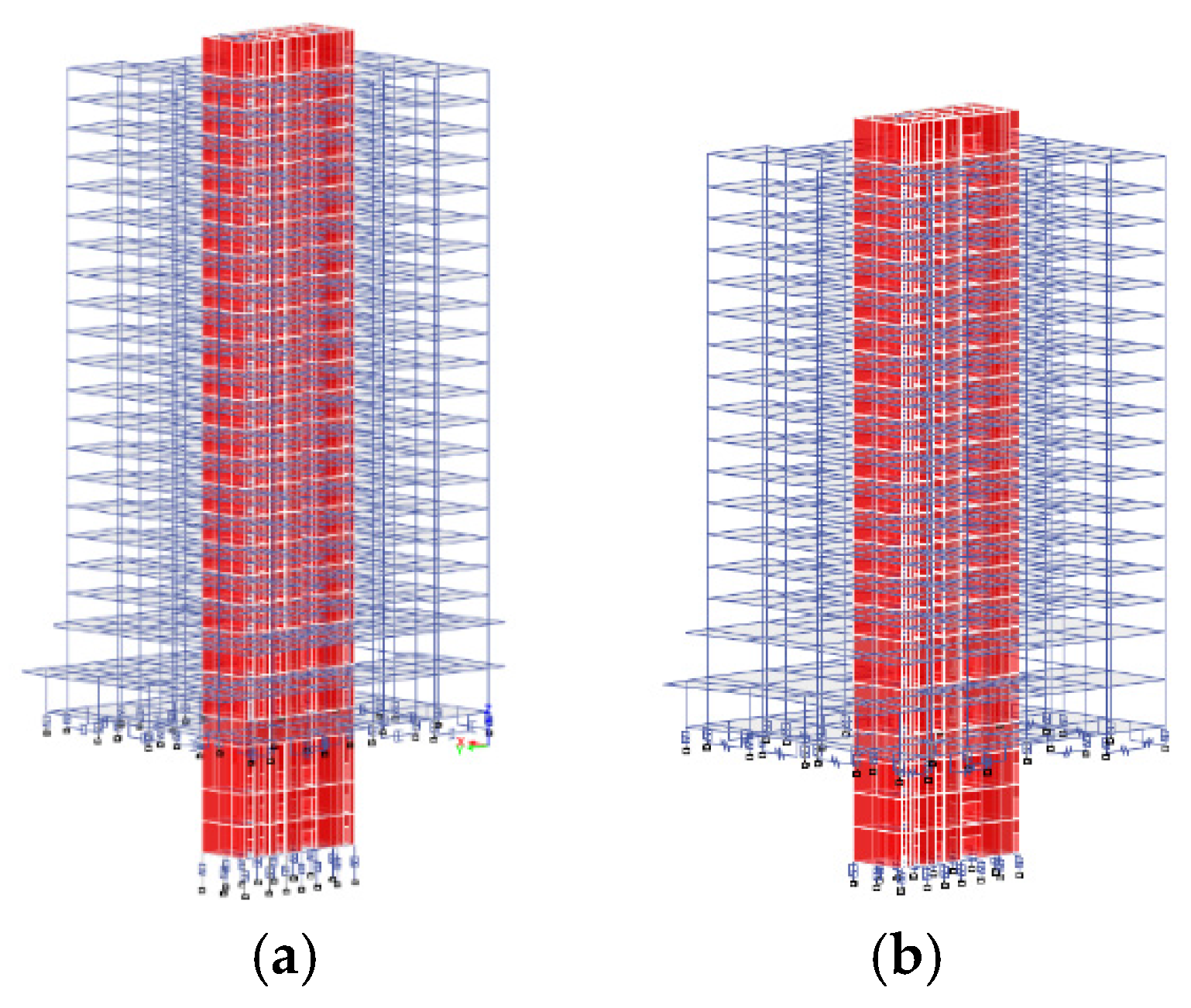
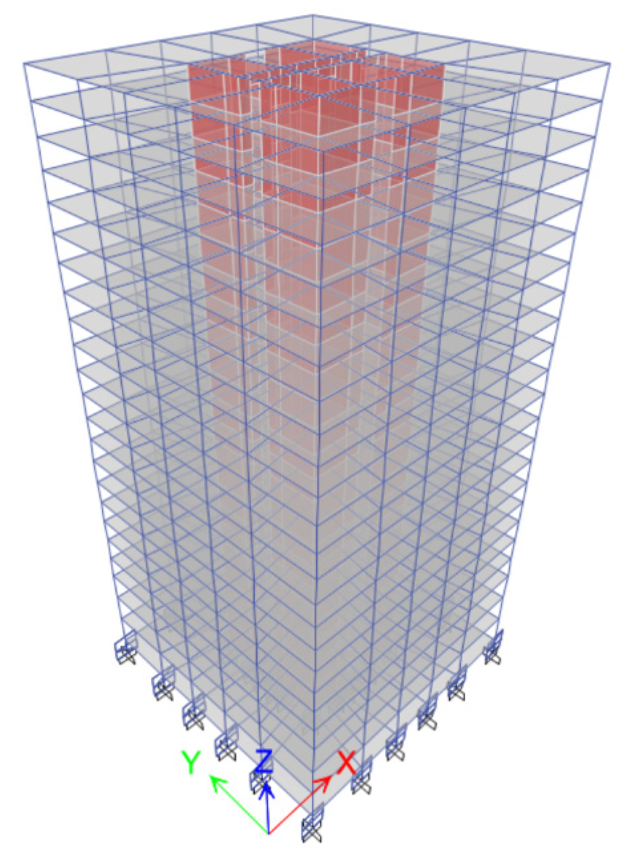
2.1. Overview of the Prototype Buildings

The selected two real engineering practices are seismically isolated RC frame-core tube tall buildings located in a near-fault region with a seismic intensity of 8.5 degree. According to GB50011-2010 [17], the 8.5 degree means that the correspond peak ground acceleration (PGA) values of the service level earthquake (SLE) (i.e., 63% probability of exceedance in 50 years), the design basis earthquake (DBE) (i.e., 10% probability of exceedance in 50 years) and the maximum considered earthquake (MCE) (i.e., 2% probability of exceedance in 50 years) are 110 cm/s2, 300 cm/s2 and 510 cm/s2, respectively. The total heights of these two buildings above the ground are 79.2 m with 22 stories (named as C1) and 65.8 m with 17 stories (named as C4), respectively. The height-to-width ratios are 2.3 and 1.91 for C1 and C4, respectively. The three-dimensional views and the plan views of the prototype buildings are presented in Figure 1 and Figure 2, respectively. The site condition belongs to the Site Class III and the second group in the GB50011-2010 [17]. The characteristic period of the site is 0.55 s. The closet distance from these two buildings to the rupture plane (i.e., Rrup) is 7.5 km. When Rrup is lower than 10 km and higher than 5 km, a near field influence coefficient with a value not less than 1.25 is introduced to consider the near field effect according to the GB50011-2010 [17]. Because the seismic design load of these buildings is extremely large and the occupancy importance of these buildings is very high, a special advisory committee (referred to as “the committee” hereafter) was established to guide and monitor the seismically isolated design. The near field influence coefficient was recommended to be 1.25 through a detailed discussion by the committee, which means the PGA values of the SLE, DBE and MCE increase to 137.5 cm/s2, 375 cm/s2 and 637.5 cm/s2, respectively.
It is notable that the basements of C1 and C4 are designed as 4 stories with a total height of 16.05 m and 14.15 m, respectively. The conventional base-isolated (CBI) scheme, which isolates the superstructure in the elevation of ±0 m, cannot satisfy the architectural design requirements. Meanwhile, the base-isolated scheme, which isolates the entire structure at the bottom of the basement, leads to a total height of approximately 95 m, thus leading to a certain extent of tensile stress in the isolators. Hence, a partially basement-isolated (PBI) scheme as shown in Figure 2 is recommended by the committee and adopted for these two buildings. Specifically, the columns are isolated in the elevation of ±0 m, while the core tubes are isolated at the bottom of the basement.
Because of the limit width of the isolation gap, which is recommended to be 600 mm by the committee, 16 NFVDs are adopted to control the MBD under the MCE. Specifically, by adopting the NFVDs, the MBD under the MCE are effectively reduced from 932 to 488 mm and 656 to 488 mm for C1 and C4, respectively. It is worth mentioning here that the authors have designed 29 different RC tall buildings located in this region and 16 NFVDs with approximately identical parameters are adopted for these buildings. The damping exponent and damping coefficient of the NFVDs are approximately 0.3 and 210 kN·s/mm. The maximum damping forces of the NFVDs in these buildings are all almost 2000 kN. Hence, the variation in numbers and parameters of NFVDs are herein not considered. The layouts of the LRB isolators, the NRB isolators and the NFVDs are schematically presented in Figure 2. The characteristic parameters of all isolators are presented in Table 1.
The critical design parameters and indexes of the prototype buildings are listed in Table 2. The fundamental period of the corresponding fixed-base structure is denoted as Tf. The isolation period, Tis, is calculated using the equivalent stiffness of the isolators when the horizontal shear strain of isolator is 100% according to the GB50011-2010 [17].
The horizontal seismic absorbing coefficient, β, which indicates the efficiency of the isolation system, is one of the most important indexes in the design of seismically isolated structures. It is defined as the maximum ratio of the shear force of the isolated structure to that of a fixed-base structure in each story subjected to the DBE [17]. For seismically isolated building with NFVDs, β is required to be no more than 0.38 according to the GB50011-2010 [17]. The horizontal seismic absorbing coefficient of C1 and C4 are both 0.36, which satisfy this specification.
The MBD under the MCE is another important design index that determines the width of the isolation gap (i.e., Dg). Specifically, MBD = max{ηi·uc}, where ηi is the torsion influence coefficient (i.e., a scale factor to consider the effects of torsion) of ith isolator with a value of 1.15 for the prototype buildings and uc is the maximum displacement of the mass center of the isolation system under the MCE [17]. For each isolator, MBD is required to be no more than the smaller of the two values of 0.55 times the effective diameter of the isolator and 3.0 times the total rubber thickness. The MBD of C1 and C4 are both 488 mm as shown in Table 2, which strictly satisfy the specification of the GB50011-2010 [17]. In addition, Dg is required to be no less than 1.2 times the MBD. As for the prototype buildings, Dg is 600 mm, which is larger than 1.2 times the MBD (i.e., 585.6 mm).
The maximum compressive and tensile stresses of the isolators are also important design indexes for the seismically isolated structures. According to the GB50011-2010 [17], the compressive stress of isolators under gravity load (i.e., σ max g ) should be no more than 15 MPa. Furthermore, the compressive and tensile stresses of isolators under the MCE (i.e., σ max p and σ max t ) should be no more than 30 MPa and 1 MPa, respectively. The typical results presented in Table 2 indicate that the design of the prototype buildings can meet the abovementioned requirements.

2.2. Design of the Study Cases

Through the introduction of the prototype buildings, it can be seen that two different heights and one seismically isolated scheme (i.e., PBI scheme) have been taken into consideration. As mentioned above, different schemes of the isolation system, which are usually determined by the real architectural design requirements, may be adopted in the design of seismically isolated RC frame-core tube tall buildings. Hence, in addition to the PBI scheme, the conventional base-isolated scheme should also be taken into account. The cases using the CBI scheme are herein designed based on the structures of C1 and C4 above the ground. Subsequently, different yield ratios are considered. 28 study cases with different yield ratios and seismically isolated schemes were redesigned based on the prototype buildings. The upper and lower limits of the yield ratios are approximately 1.5% and 3.5%, respectively. Different yield ratios are achieved through the adjustment of the type and quantity of the isolators. Detailed information (consisting of the height, seismically isolated scheme and yield ratio) and the corresponding Tis of these cases are presented in Table 3.
The single-degree-of-freedom (SDOF) model and multi-degree-of-freedom (MDOF) shear model are widely used to guide the preliminary design and conceptual research of seismically base-isolated structures exhibiting significant shear deformation mode [9,22,24,27,28,29]. However, the RC frame-core tube buildings exhibit a flexural-shear deformation mode [30]. A reliable numerical model that can consider such deformation characteristic is required. The refined finite element (FE) model, which is widely acknowledged to be capable of reflecting such deformation characteristic [31,32,33,34], is adopted here. The general-purpose commercial software ETABS [35] is used to establish the refined FE model and conduct the seismically isolated design as well as the seismic performance assessment of the abovementioned 28 cases. It is notable that the superstructure of the isolated buildings usually experiences minor damage as expected; therefore, an elastic model for the superstructure is usually adopted [36,37]. Because of this, the beams and columns of the superstructure are modeled with elastic frame elements. The shear walls are simulated using the elastic shell element. In contrast, as the plastic response of the seismically isolated structures is mostly concentrated in the isolation system, a plastic model is usually adopted for the isolation system. Hence, the Rubber Isolator element and the Gap element are herein adopted for the isolators, while the Damper-Exponential element is used for the NFVDs. The abovementioned modeling methods are widely adopted and have been proved to be reliable [20,38].
For the ground motions, two natural ground motion records and one artificial ground motion are used to design the study cases and investigate the rational yield ratio according to GB50011-2010 [17]. The response spectrum of each ground motion is compared with the design response spectrum as shown in Figure 3. The ranges of interest for the period are 1.31–1.59 s for the fixed-base structures and 3.90–4.95 s for the seismically isolated structures. It can be found that the mean response spectrum agrees well with the design response spectrum at these period ranges. The ground motions are scaled to 375 cm/s2 and 637.5 cm/s2 to conduct time history analyses (THAs) under DBE and MCE, respectively. The indexes, including σ max g , σ max p and σ max t , all meet the requirements specified in the GB50011-2010 [17]. The β and the MBD under the MCE are critical indexes to evaluate a rational yield ratio. Hence, these two critical indexes of 28 study cases will be presented and discussed in detail in the following section.

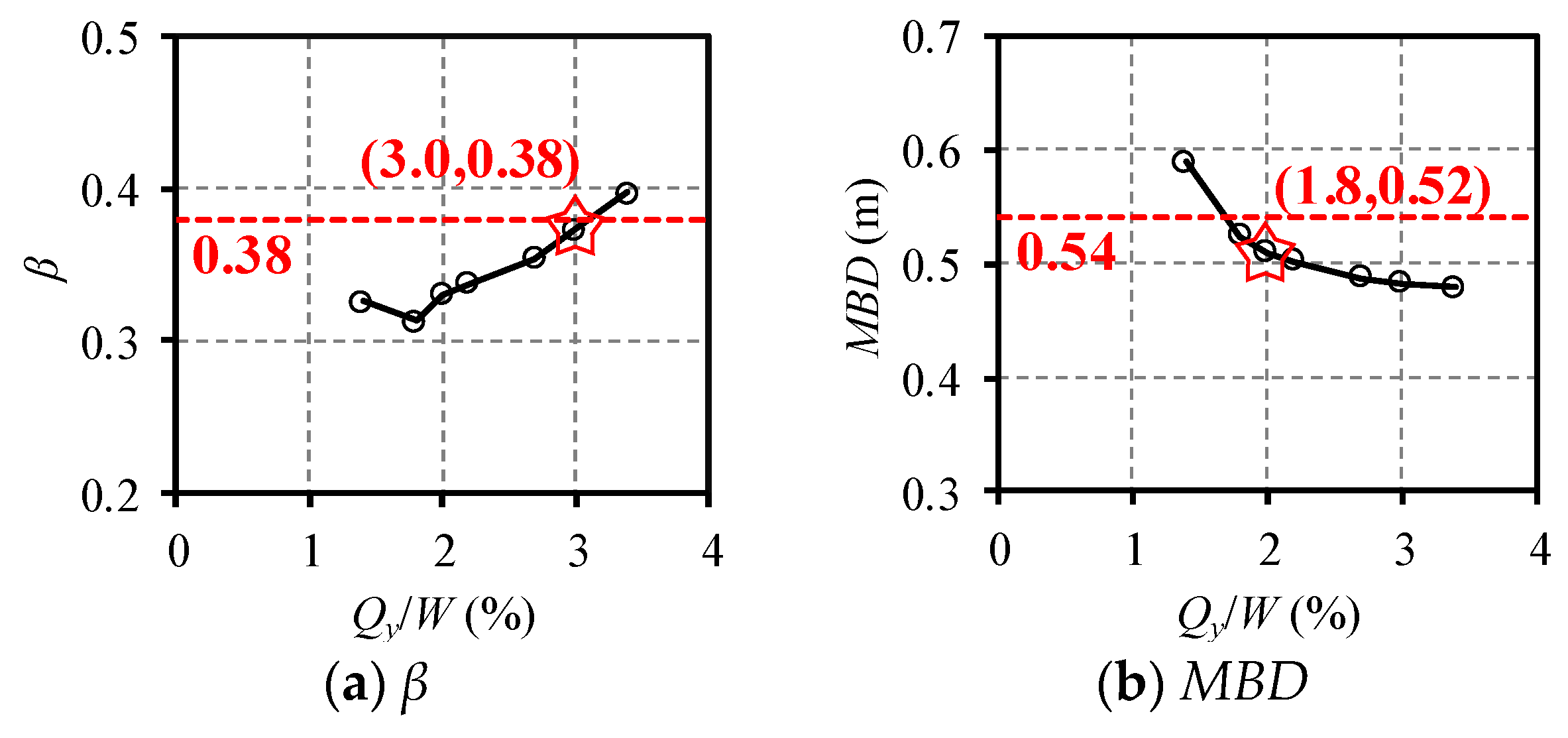
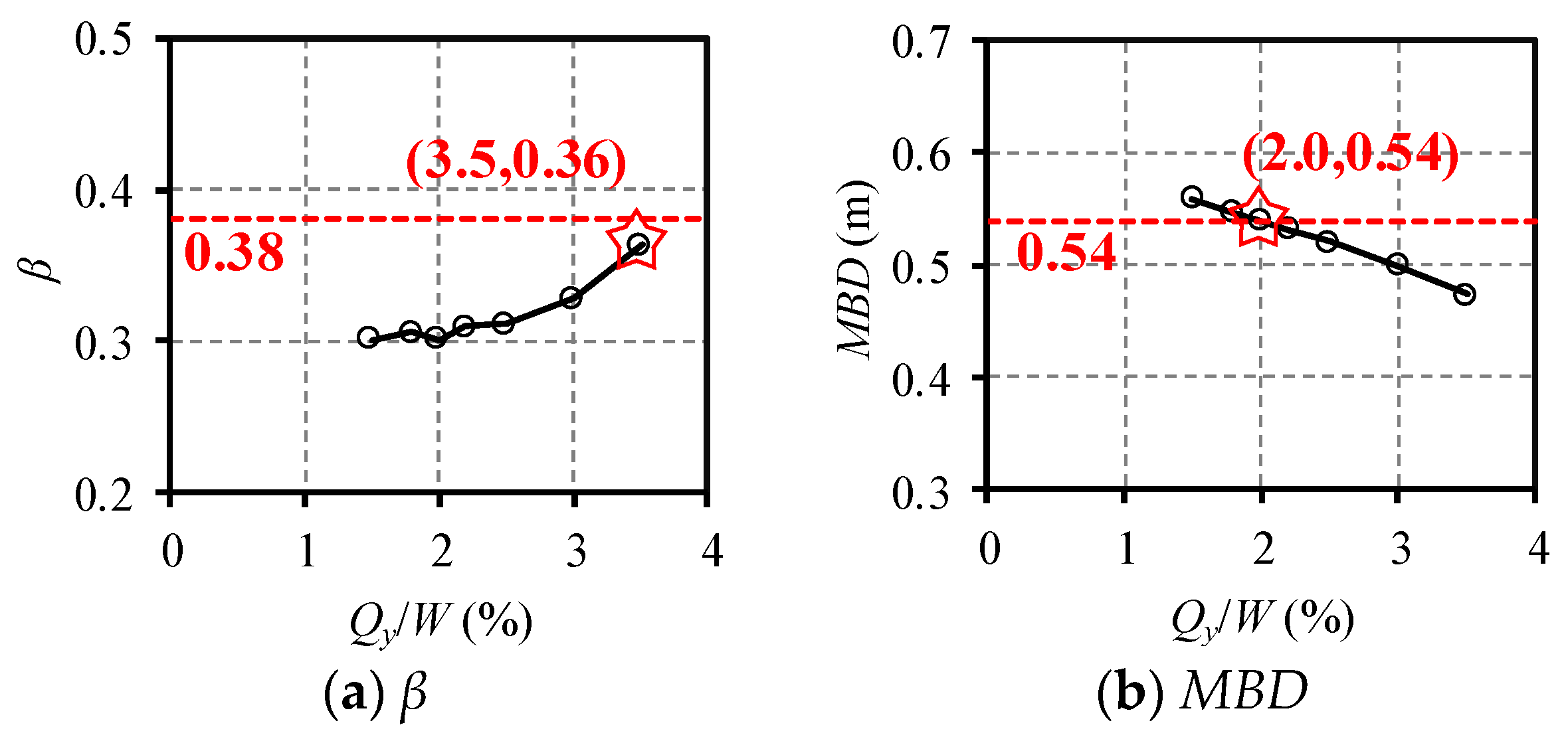
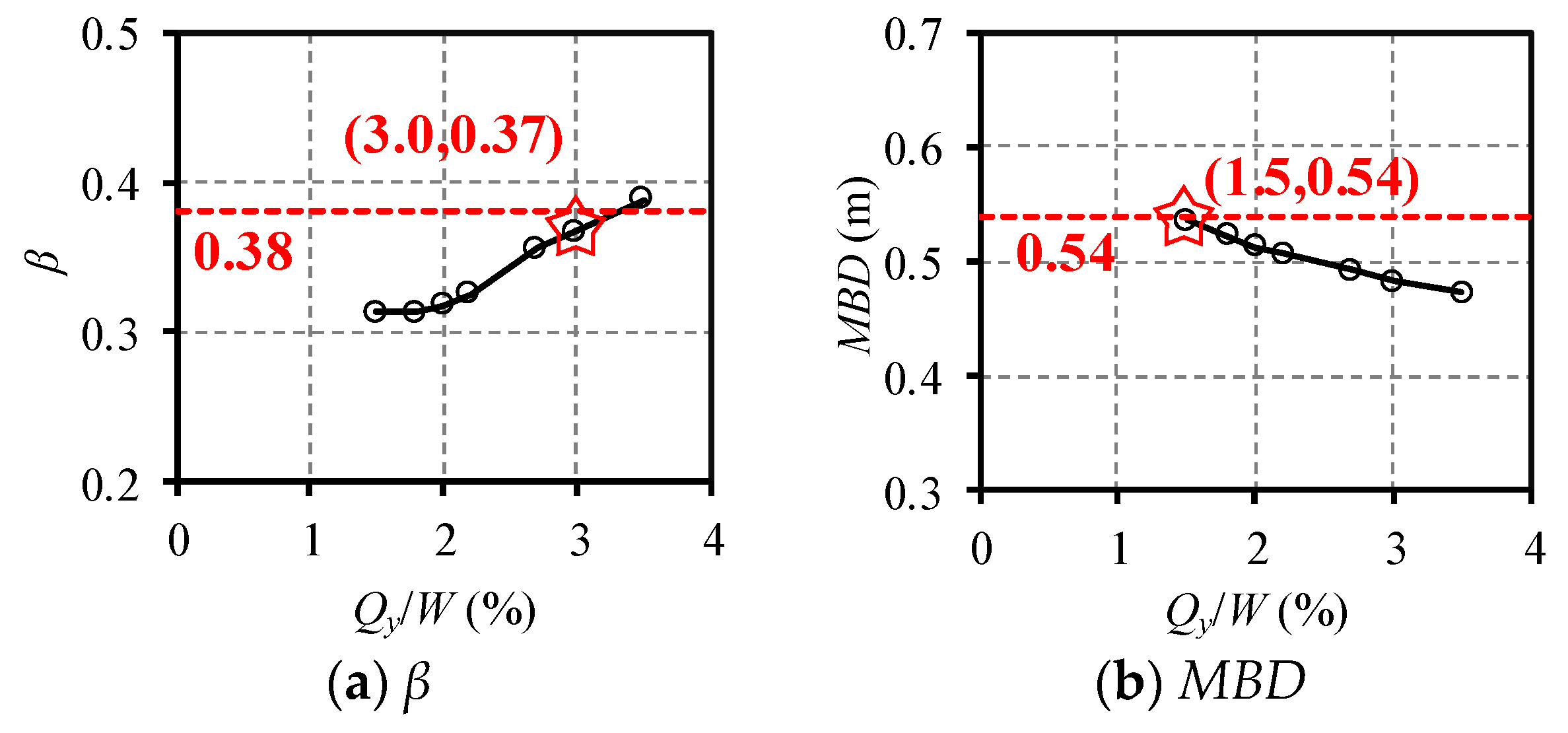
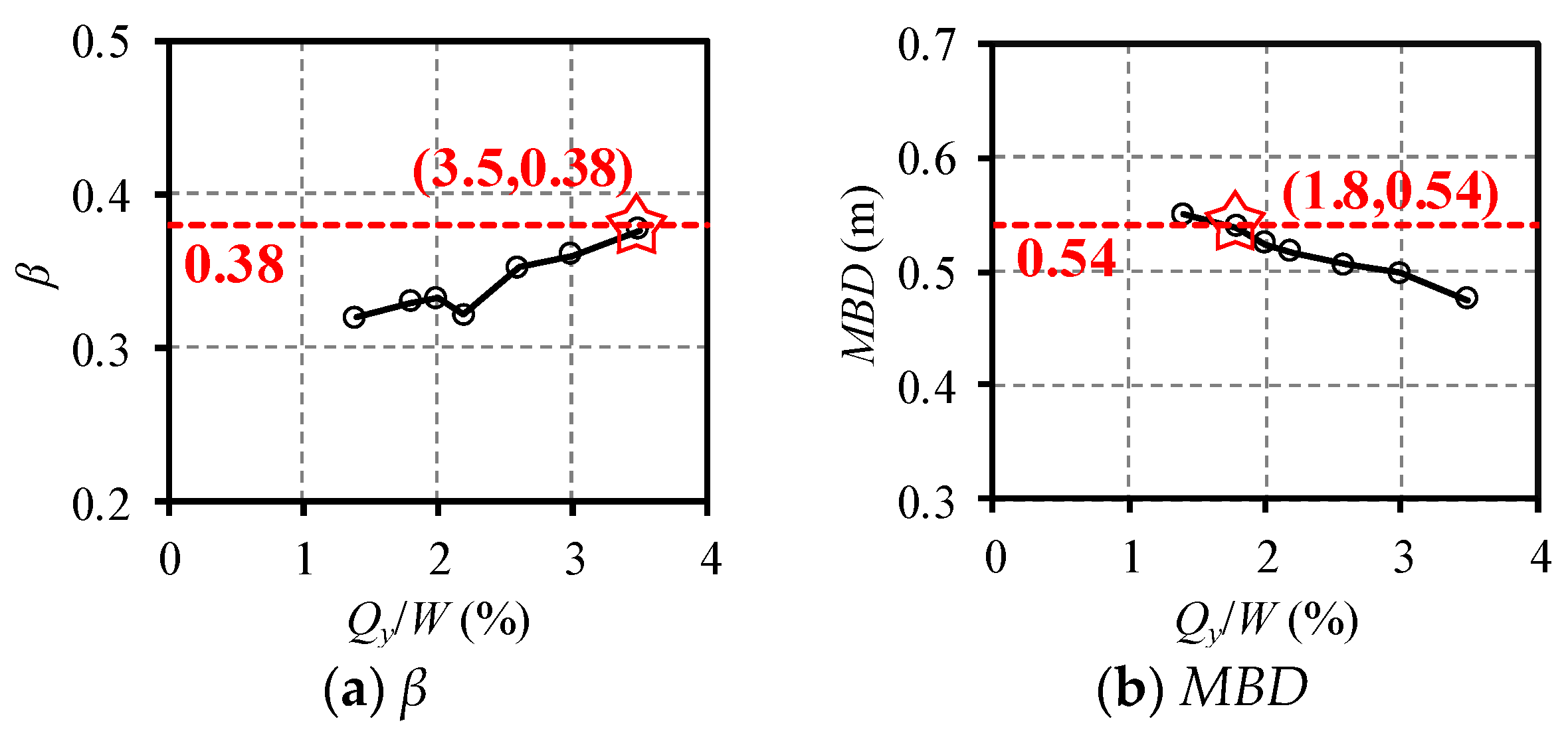
2.3. Rational Value of the Yield Ratio

To identify the rational yield ratio for the RC frame-core tube tall buildings located in high seismic regions, the following two principles are followed: (1) the horizontal seismic absorbing coefficient, β, is required to be no more than 0.38 as specified in the GB50011-2010 [17]; (2) the MBD under the MCE should not exceed 540 mm. In consideration of the difficulties in design of such seismically isolated tall buildings, the committee recommended that the limit width of the isolation gap could increase to 650 mm, which meant that the MBD could raise to approximate 540 mm (i.e., 650/1.2 ≈ 540 mm).
The values of β and MBD for the 28 study cases with different yield ratios and different seismically isolated schemes are calculated and presented in Figure 4, Figure 5, Figure 6 and Figure 7. The following conclusions can be drawn:
(1) The recommended upper limit of the yield ratio is 3% and the upper limit is determined by the β. When the yield ratio is no more than 3%, the value of β of all 28 study cases do not exceed 0.38, which means that the expected efficiency of the isolation system is successfully achieved and 3% can be regarded as the upper limit. In addition, β decreases with the decrease in yield ratio, indicating that a lower yield ratio can achieve a better isolation efficiency. However, the value of β becomes steady when the yield ratio decreases to 2%, which means the continuous decrease of the yield ratio below 2% cannot lead to better isolation efficiency.
(2) The upper limit of the yield ratio can increase to a certain level when the building height is smaller than 80 m or the CBI scheme is adopted. The upper limit of the yield ratios of C1 with the height of 79.2 m (3% for the PBI scheme) is lower than that of C4 with the height of 65.8 m (3.5% for the PBI scheme), indicating a higher upper limit of the yield ratio can be adopted for a building with a height lower than approximately 80 m. In addition, when the yield ratios of the PBI scheme and the CBI scheme both reached 3% for C1, the value of β for the CBI scheme is lower than that for the PBI scheme, indicating that a larger value of the yield ratio can be adopted for the CBI scheme.
(3) The recommended lower limit of the yield ratio is 2%. When the yield ratio is no less than 2%, the MBD under the MCE are all lower than 540 mm, which satisfy the requirements specified by the limit value of the isolation gap. The MBD generally decreases with the increase of the yield ratio, indicating that a higher yield ratio can better control the MBD, thereby satisfying the demand of the isolation gap. In addition, with the increase of the height of the building, the lower limit of the yield ratio can adopt a smaller value (e.g., 1.8% for C1 with the PBI scheme). However, the isolation efficiency becomes steady when the yield ratio decreases to 2% as mentioned above, while a considerable increase of the MBD is observed. Hence, the lower limit of the yield ratio with a value of 2% is recommended.
Based on the above discussion, it can be concluded that the upper and lower limits of the yield ratio are determined according to the requirements of the horizontal seismic absorbing coefficient and the width of the isolation gap, respectively. A yield ratio in the range of 2–3% is considered rational for the seismically isolated RC frame-core tube tall buildings.

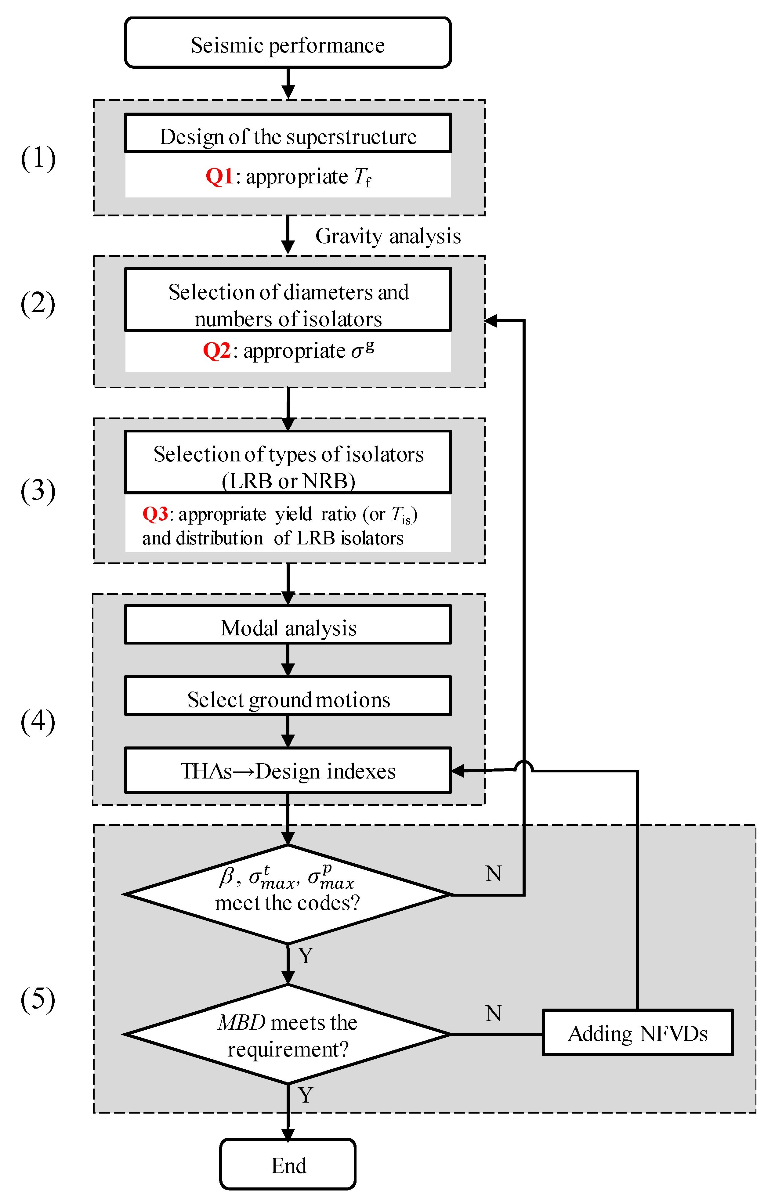
3. Design Method for Seismically Isolated RC Frame-Core Tube Tall Building

3.1. Traditional Design Method

For the traditional design method of seismically isolated tall buildings, the seismic performance targets, including the limits of the β and the MBD under the MCE, are determined first. According to the GB50011-2010 [17], β is required to be no more than 0.40 and 0.38 for the structures without and with the NFVDs in the isolation system, respectively. This indicates that the seismic forces of the superstructure are similar to that of a fixed-base structure with one-degree lower seismic intensity. Due to this fact, the seismically isolated structures are designed following a step-by-step iterative design method as shown in Figure 8.
The design method can be divided into 5 steps:
(1) Design of the superstructure.
The superstructure is first designed as a fixed-base structure with a one-degree lower seismic intensity. An appropriate superstructure is the basis for the seismic design of the isolated building. The Tf is the most critical index to be determined in this step, because it is highly associated with the seismic force of the structure and the seismic absorbing coefficient.
(2) Selection of the isolator numbers and sizes.
The numbers and sizes of isolators are determined according to the appropriate compressive stress of each isolator under gravity load (referred to as σg hereafter). It is notable that the requirements of σg for different isolators, including the isolators under the columns, the corner of core tube, the outer wall and the inner wall, are different. Due to the significant overturning effect of the RC frame-core tube tall buildings, the isolators under the columns and the corner of the core tube may possibly be under tension, a higher σg is usually required for these isolators. However, an appropriate σg for different isolators of RC frame-core tube buildings has rarely been investigated and reported, which is critical for the selection of numbers and sizes of isolators.
(3) Selection of the isolator types.
Determining the type of the isolators (LRB or NRB) is a key step in the design of such buildings. This can significantly affect the seismic performance of the isolation system and the entire structure. Specifically, an appropriate yield ratio is required first, as mentioned above. In addition, a rational distribution of the LRB isolators should be carefully designed to avoid torsion effect. However, a comprehensive investigation on the appropriate yield ratio and the distribution of the LRB isolators has rarely been proposed for the RC frame-core tube seismically isolated tall buildings.
(4) Calculation of the design indexes.
After the preliminary isolation system is established, critical design indexes, including β, MBD under the MCE, σ max p and σ max t , are assessed to validate the feasibility of the isolation system. The Tis is initially obtained through modal analysis. Then, a set of appropriate ground motions are selected according to Tf and Tis. The THAs are conducted for these two structures and critical design indexes are calculated.
(5) Validation and/ or modification of isolation system.
Three design indexes, including β,   σ max p and σ max t , are evaluated. If one of these indexes cannot meet the requirements, the sizes, numbers or types of the isolators will be constantly modified (i.e., iterate from step 2) until these indexes can satisfy the requirements. Subsequently, the MBD under the MCE is examined. The introduction of the NFVDs in the isolation system is recommended, if the MBD under the MCE exceeds the limit value specified by the allowable width of the isolation gap.
Numerous iterations are usually required to achieve a satisfactory isolation system for the traditional design method, leading to extremely low efficiency. This is attributed to the following three critical problems:
(1) An appropriate Tf is currently not available for RC frame-core tube buildings.
(2) The appropriate ranges of σg for the isolators at different locations, especially those under the columns and the corner of the core tube, are not proposed yet.
(3) A rational range of the yield ratio and associated distribution of LRB isolators have not been recommended.
Based on the above, it can be concluded that a high-efficiency design method with emphasis on the solutions of abovementioned three critical problems is required.

3.2. Proposed High-Efficiency Design Method

According to the above requirements, solutions for the three critical problems are firstly proposed here.
(1) For the appropriate Tf, a statistical regression analysis is conducted based on the seismically isolated tall buildings designed by the authors, as shown in Figure 9. An equation, which describes the relationship between the height and Tf, is obtained as shown in Equation (1). Here, H represents the total height of the structure.
Tf = 0.193H0.5
(2) A certain extent of tensile stress may be observed for the isolators under the columns due to the overturning effect, a relatively large σg is therefore usually adopted for these isolators. However, a σg with excessive value is also not recommended because it may lead to a large σ max c , which may exceed the specified limit value. Based on the design experience, the σg is recommended to be approximately 10–12 MPa for the isolators under the columns. It is notable that the stress of the isolators under the corner of the core tube when subjected to MCE is lower than this of the isolators under the columns. Hence, a lower σg can be adopted for such isolators and a σg with the value ranged from 8 to 10 MPa is recommended for the isolators under the corner of the core tube, which is also based on the design experience.
(3) The rational range of the yield ratio has been investigated in Section 2 and has been recommended in the range of 2–3%. To avoid the torsion effect, the LRB isolators are recommended for the columns and the corner of the core tube in the RC frame-core tube tall buildings. If these LRB isolators can lead to an acceptable yield ratio, the requirements of β,   σ max p and σ max t are considered easily satisfied.
Based on the above discussion, a new high-efficiency design method, as shown in Figure 10, is proposed for the seismically isolated RC frame-core tube tall buildings. The entire design procedure is presented as follows:
(1) Design of the superstructure.
According to the height of the building, an appropriate value of Tf is calculated using Equation (1). Then, the superstructure is designed as a fixed-base structure with one-degree lower seismic intensity and with a Tf value approximate to the calculated value.
(2) Selection of isolator numbers and sizes.
Gravity analysis is conducted to calculate the axial forces under the columns and the shear walls. Then, according to the recommended compressive stress for different isolators, the demand for the area of the corresponding isolators can be calculated and appropriate numbers and sizes of the isolators can be selected.
(3) Selection of the isolator types.
LRB isolators are adopted for the isolators under the columns and the corner of the core tube. Then, the yield ratio is calculated. If the calculated yield ratio is lower than 2%, more LRB isolators are recommended to be adopted under the external wall. If the calculated yield ratio is higher than 3%, the LRB isolators under the corner of the core tube can be reduced first, followed by those under the columns.
(4) Calculation of the design indexes.
Modal analysis is conducted firstly to calculate the Tis and appropriate ground motions are selected. Based on these, THAs are performed to calculate the critical design indexes.
(5) Validation and/or modification of isolation system.
Because of the rational yield ratio adopted, β, σ max p and σ max t can usually satisfy the requirements. If not, only limit modifications of the isolators are required. Subsequently, the MBD under the MCE is examined. If the MBD exceeds the limit value, the NFVDs are recommended to be introduced in the isolation system. It is notable that the quantity and parameters of the NFVDs can be determined with a few number of iterations.
The application of this high-efficiency design method will be explained in detail in the following section.

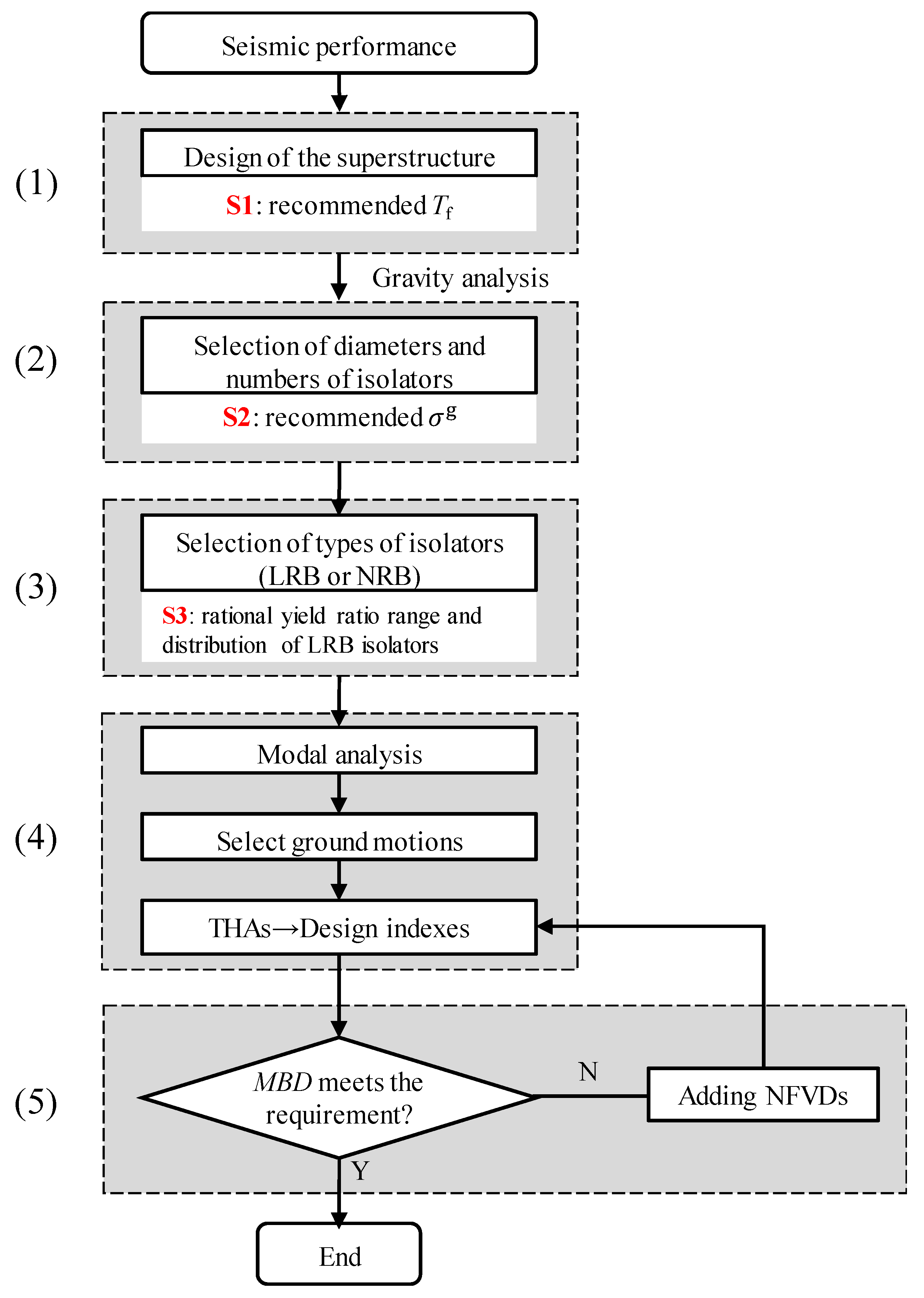
4. Application of the Design Method

To validate the reliability and applicability of the proposed design method, a seismically isolated RC frame-core tube tall building is designed using this method. The seismic intensity and the site condition of this building are identical to those of the prototype buildings in Section 2. The near field influence coefficient with a value of 1.25 is also adopted. The PGA values of the SLE, DBE and MCE are also 137.5 cm/s2, 375 cm/s2 and 637.5 cm/s2, respectively. The total height of the building is 84.1 m with 23 stories above the ground and the height-to-width ratio is 2.06. The three-dimensional view of the entire building and one typical floor are presented in Figure 11 and Figure 12, respectively.
According to the GB50011-2010 [17], β is required to be no more than 0.40 and 0.38 for the structures without and with NFVDs in the isolation system, respectively. This indicates that the seismic forces of the superstructure are similar to those of a fixed-base structure with one-degree lower seismic intensity (i.e., 7.5 degree). The Dg value of this building is 600 mm, leading to an upper limit value of the MBD under the MCE of 500 mm, which is identical to that of the above prototype buildings.

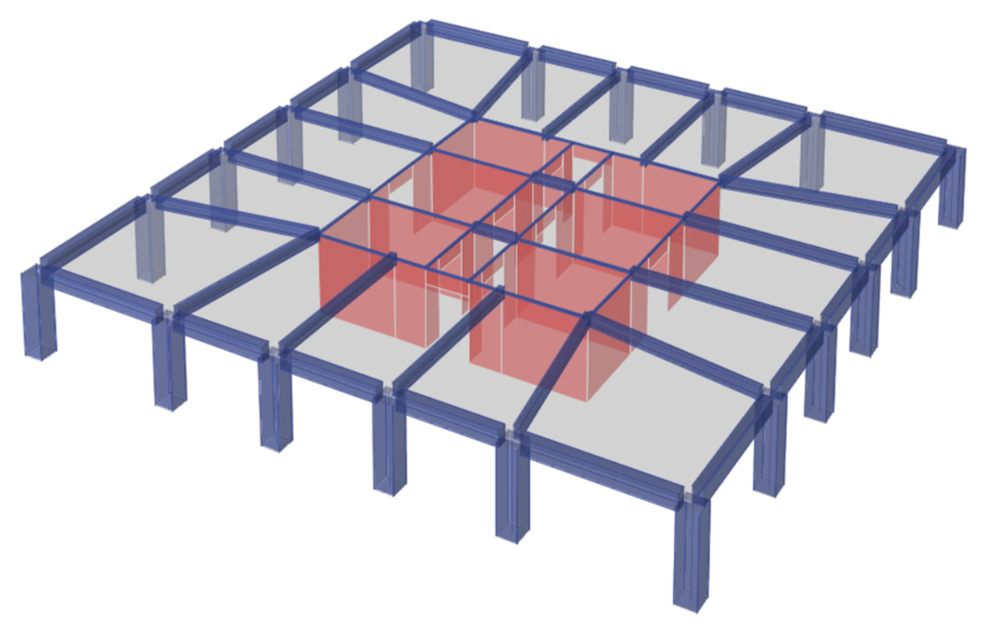
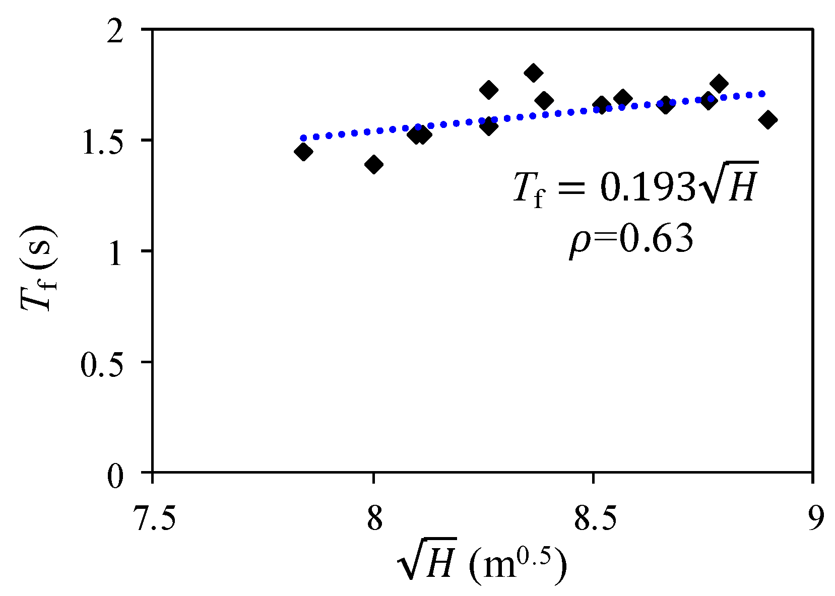
4.1. Design of the Superstructure

The superstructure of the isolated building is designed as a fixed-base structure with a seismic intensity of 7.5 degree, along with a near field coefficient of 1.25. The corresponding PGA values of the SLE, DBE and MCE are also 68.75 cm/s2, 187.5 cm/s2 and 387.5 cm/s2, respectively. The seismic design of the superstructure is conducted using the structural design software PKPM [39] under the SLE.
The appropriate Tf is calculated using Equation (1) with a value of 1.77 s. Hence, the superstructure is designed with a Tf of 1.798 s and 1.697 s for the Y-direction and the X-direction, respectively, which can approximately satisfy the requirement. The section size and the concrete strength of the superstructure are listed in Table 4. The total gravity load of the entire structure is 617338 kN. The distribution of the inter-story drift ratio of the superstructure under response spectrum analysis is presented in Figure 13. The corresponding maximum inter-story drift ratios of the X and Y directions are 0.066% and 0.072%, respectively, which are both lower than the limit value (i.e., 0.125%) specified in the GB50011-2010 [17].
It is worth mentioning here that the design of the seismically isolated building is mostly conducted using ETABS. Therefore, a reliable refined FE model should be built using ETABS. To validate the reliability of this model, typical analytical results obtained from ETABS are compared with those from PKPM. After conducting the modal analysis and the response spectrum analysis under the SLE, the fundamental periods and distribution of the inter-story drift ratios predicted by ETABS and PKPM are found to agree well with each other, with only 3% of difference. This value can be considered acceptable and therefore, validates the reliability of the refined FE model.

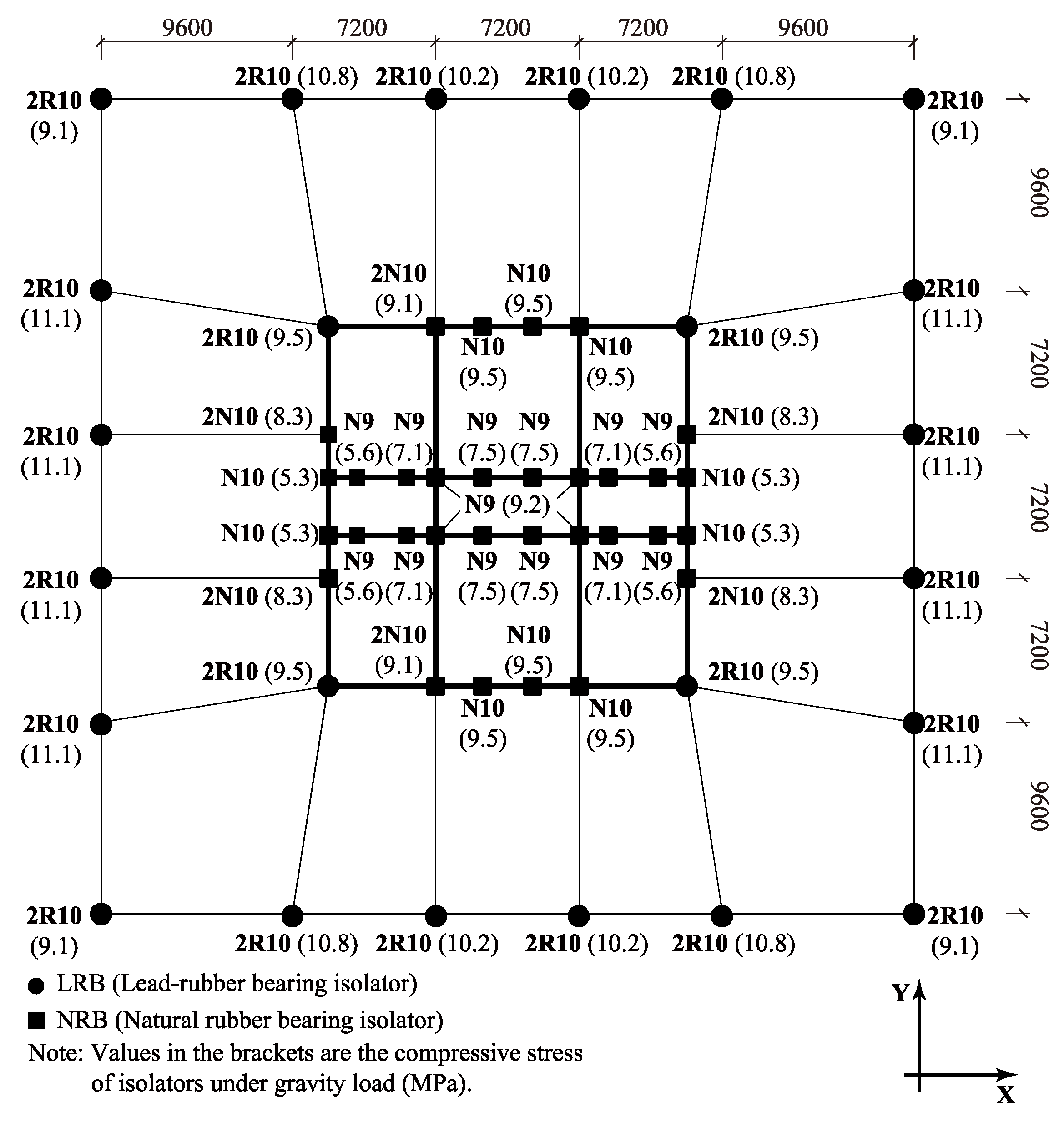
4.2. Selection of the Isolator Numbers and Sizes

Gravity analysis is conducted to obtain the axial force of the columns and shear walls at the ground story, in order to determine the sizes and numbers of the isolators under these columns and shear walls. As mentioned above, the σg of isolators under the columns and the corner of the core tube are recommended to be approximately 10–12 MPa and 8–10 MPa, respectively. To achieve these, the sizes and the diameters of the isolators under the columns and the shear walls are determined as follows:
(1) The area of the isolators under the columns except those under the corner columns is required to be no less than 1,452,250 mm2. Hence, two isolators with diameter of 1000 mm are adopted, with the corresponding value of σg found to be approximately 11 MPa. The identical numbers and diameters of the isolators under the corner columns are adopted here for convenience, although a relatively lower σg with a value of 9.1 MPa is achieved.
(2) The area of the isolators under the corner of the core tube is required to be no less than 1,491,500 mm2. Two isolators with diameter of 1000 mm are also used, leading to the value of 9.5 MPa for σg.
(3) For the external and inner shear walls, the isolators with a diameter of 1000 mm and 900 mm are adopted, respectively. This difference in diameters is attributed to the fact that the axial force of the external shear walls is larger than that of the inner shear walls.
Based on the above discussion, the sizes and numbers of isolators are determined and the process is schematically illustrated in Figure 14. In addition, the σg value of each isolator is also presented in Figure 14.

4.3. Selection of the Isolator Types (LRB or NRB)

The torsion effect of the seismically isolated tall buildings should be controlled strictly. To avoid the torsion, the rigid center of the isolation system is required to be approximately identical to the mass center of the superstructure, which is specified in the technical specification for seismic-isolation with laminated rubber bearing isolators (CECS126:2001) [40]. To achieve this, LRB isolators are usually adopted for the columns and the corner of the core tube in RC frame-core tube tall buildings. In addition, an index named eccentricity of the isolation system is introduced to quantitatively evaluate the potential torsion effect.
Based on the above, LRB isolators are adopted for the isolators under the columns and the corner of the core tube, while NRB isolators are adopted for other isolators as shown in Figure 14. The yield ratio calculated has a value of 2.3%, which lies in the proposed rational range of the yield ratio (i.e., 2–3%), indicating that there is no need to add other LRB isolators. Then, the eccentricity of isolation system is calculated to have the values of 0.0043% and 0.0007% in the X and Y directions, respectively, which are both lower than the limit of 3%.

4.4. Calculation of the Design Indexes

The fundamental periods of the isolated structure are 4.294 s and 4.242 s for the Y direction and the X direction, respectively. Based on the Tf and Tis values, three ground motions, including two natural ground motion records and one artificial ground motion, are selected according to GB50011-2010 [17]. The response spectrum of each ground motion is compared to the design response spectrum as shown in Figure 15. It can be found that the mean response spectrum agrees well with the design response spectrum at the periods of Tf and Tis. Subsequently, THAs are conducted for these two structures. The critical design indexes, including β under DBE, MBD under the MCE, σ max t and σ max p are calculated. The critical design indexes and parameters are presented in Table 5.

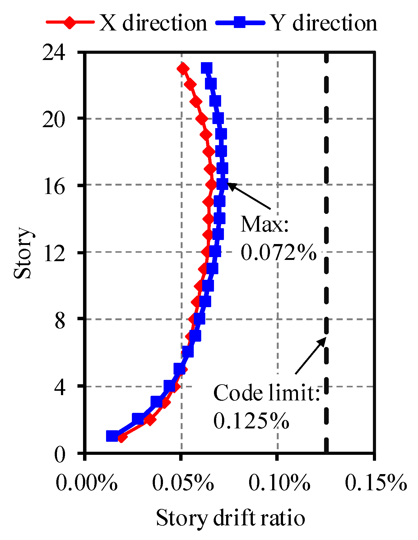
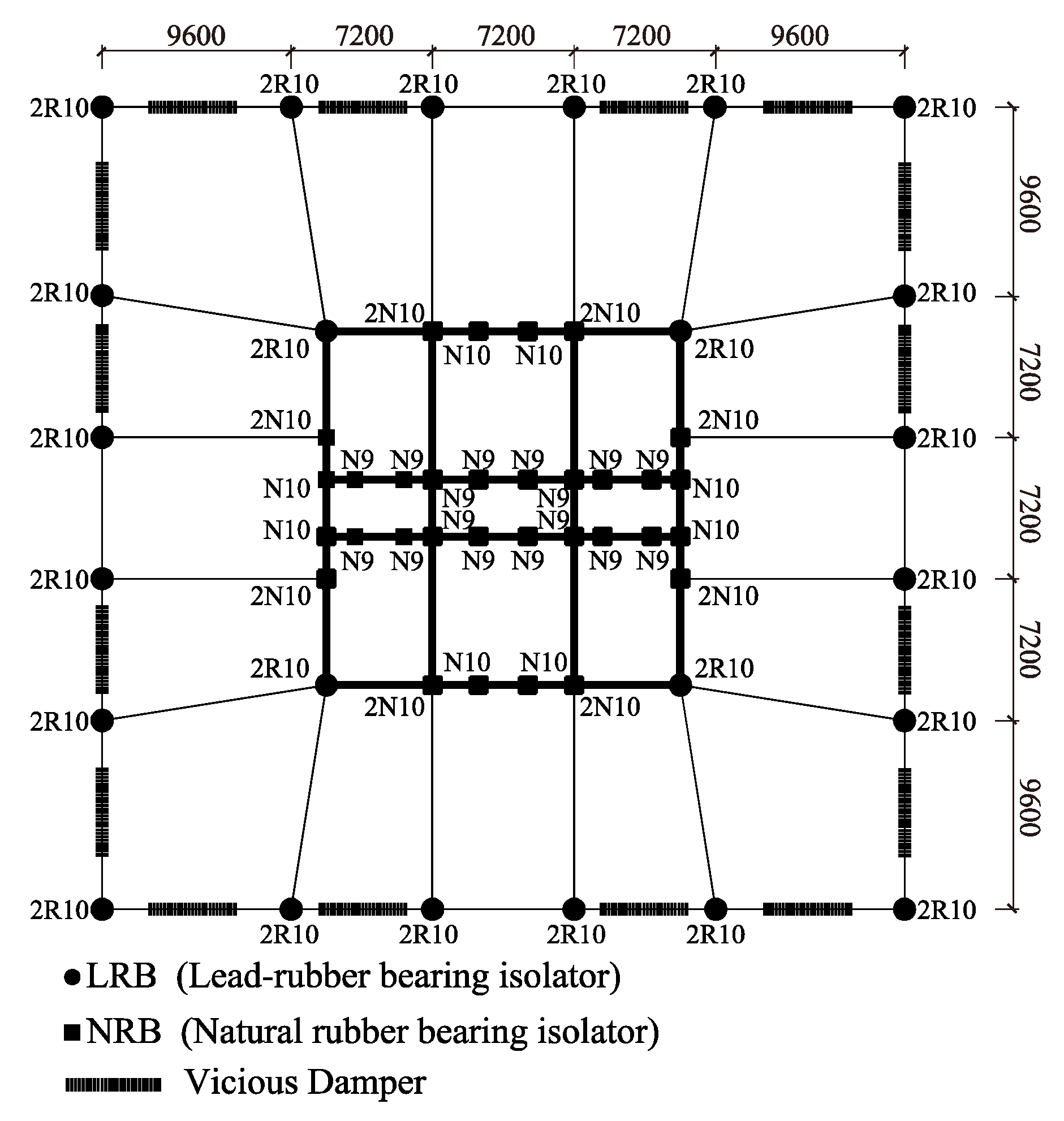
4.5. Validation and Modification of the Isolation System

It can be found from Table 5 that the efficiency of the isolation system (i.e., β) and the stresses of the isolators under the gravity and seismic loads all satisfy the requirements specified in the GB50011-2010 [17], which is consistent with the expected results of the proposed design method. However, the MBD under the MCE with a value of 788 mm exceeds the limit value of 500 mm. As expected and recommended by the proposed method, the NFVDs are introduced for further control.
From the design experience of the 29 seismically isolated tall buildings conducted by the authors, 16 NFVDs are adopted in the isolation system as shown in Figure 16. The parameters of the NFVDs are determined by a few number of trials. When the damping exponent and the damping coefficient reach 0.3 and 220 kN·s/mm, respectively, the MBD under the MCE decreases to 493 mm, which is lower than 500 mm. The maximum damping forces of these NFVDs are approximately 2000 kN. The corresponding critical design parameters and indexes are presented in Table 6. It is obvious that the seismically isolated structure achieves the expected seismic performance.
The above discussion demonstrates that the numbers, sizes and types of isolators can be directly determined with the proposed method. Only limited numbers of iteration are conducted to determine the quantity and the properties of the NFVDs. The efficiency can be substantially increased with the proposed design method.

5. Conclusions

The rational yield ratios of the isolation system for the RC frame-core tube buildings are investigated using 28 carefully designed study cases, which are designed based on two real engineering practices and considers the influences of total heights, yield ratios and seismically isolated schemes. Based on this, a high-efficiency design method is proposed for such buildings. Subsequently, a seismically isolated RC frame-core tube tall building with a height of 84.1 m is designed using the proposed design method. The following conclusions can be drawn:
(1) The upper and the lower limits of the yield ratio are determined according to the requirements of the horizontal seismic absorbing coefficient and the width of the isolation gap, respectively.
(2) A yield ratio in the range of 2–3% is considered rational and recommended for the seismically isolated RC frame-core tube tall buildings.
(3) A typical seismically isolated RC frame-core tube tall building is successfully designed using the proposed method, thereby validating the rationality, reliability and efficiency of the proposed method.
This paper focuses on the seismically isolated RC frame-core tube tall buildings with moderate height-to-width ratios, in which significantly overturning effect is not observed. Further investigations on such building with significantly overturning effect are required to be conducted. The research outcome can serve as a reference for further development of the seismic design method for seismically isolated RC frame-core tube tall buildings.

Acknowledgments

The authors are grateful for the financial support received from the National Key Technology Research and Development Program of China (No. 2017YFC0703602), the Beijing Advanced Innovation Center for Future Urban Design (No. UDC2016030200) and the Research project of Beijing University of Civil Engineering and Architecture (KYJJ2017005).

Author Contributions

Aiqun Li and Linlin Xie conceived the concept, Linlin Xie guided the students to complete the specific research and proposed the high-efficiency design method, Cantian Yang and Lide Liu investigated the rational yield ratio and applied the design method, Demin Zeng reviewed the study cases, Cantian Yang wrote the paper.

Conflicts of Interest

The authors declare no conflict of interest.

References

  1. Formisano, A.; Chieffo, N.; Marius, M. Fragility and resilience curves of an urbanised sector in the district of Naples. Int. J. Constr. Res. Civ. Eng. 2017, 3, 58–67. [Google Scholar] [CrossRef]
  2. Bozza, A.; Asprone, D.; Fabbrocino, F. Urban resilience: A civil engineering perspective. Sustainability 2017, 9. [Google Scholar] [CrossRef]
  3. Tipler, J.; Deierlein, G.; Almufti, I. Seismic Resilience of tall Buildings-Benchmarking Performance and Quantifying Improvements; Stanford University: Stanford, CA, USA, 2014. [Google Scholar]
  4. Pant, D.; Montgomery, M.; Christopoulos, C.; Xu, B.; Poon, D. Viscoelastic coupling dampers for the enhanced seismic resilience of a megatall building. In Proceedings of the 16th World Conference on Earthquake Engineering, Santiago, Chile, 9–13 January 2017. [Google Scholar]
  5. Tian, Y.; Lu, X.; Lu, X.Z.; Li, M.K.; Guan, H. Quantifying the seismic resilience of two tall buildings designed using Chinese and US codes. Earthq. Struct. 2016, 11, 925–942. [Google Scholar] [CrossRef]
  6. Heaton, T.; Hall, J.; Wald, D.; Halling, M. Response of highrise and base-isolated buildings to a hypothetical M(w)7.0 blind thrust earthquake. Science 1995, 267, 206–211. [Google Scholar] [CrossRef] [PubMed]
  7. Pan, P.; Zamfirescu, D.; Nakashima, M.; Nakayasu, N.; Kashiwa, H. Base-isolation design practice in Japan: Introduction to the post-Kobe approach. J. Earthq. Eng. 2005, 9, 147–171. [Google Scholar] [CrossRef]
  8. Zhu, H.; Zhou, F.; Yuan, Y. Development and analysis of the research on base isolated structures. Eng. Mech. 2014, 3. [Google Scholar] [CrossRef]
  9. Higashino, M.; Okamoto, S. Response Control and Seismic Isolation of Buildings; Routledge: Abingdon, UK, 2006; ISBN 978-0-415-36623-6. [Google Scholar]
  10. Zhou, Y.; Chen, P. Shaking table tests and numerical studies on the effect of viscous dampers on an isolated RC building by friction pendulum bearings. Soil Dyn. Earthq. Eng. 2017, 100, 330–344. [Google Scholar] [CrossRef]
  11. Pan, P.; Shen, S.; Shen, Z.; Gong, R. Experimental investigation on the effectiveness of laminated rubber bearings to isolate metro generated vibration. Measurement 2017. [Google Scholar] [CrossRef]
  12. Ye, K.; Li, L.; Zhu, H. A modified Kelvin impact model for pounding simulation of base-isolated building with adjacent structures. Earthq. Eng. Eng. Vib. 2009, 8, 433–446. [Google Scholar] [CrossRef]
  13. Ubertini, F.; Comodini, F.; Fulco, A.; Mezzi, M. A Simplified parametric study on occupant comfort conditions in base isolated buildings under wind loading. Adv. Civ. Eng. 2017. [Google Scholar] [CrossRef]
  14. Sorace, S.; Terenzi, G. Analysis and demonstrative application of a base isolation/supplemental damping technology. Earthq. Spectra 2008, 24, 775–793. [Google Scholar] [CrossRef]
  15. Cancellara, D.; De Angelis, F. Assessment and dynamic nonlinear analysis of different base isolation systems for a multi-storey RC building irregular in plan. Comput. Struct. 2017, 180, 74–88. [Google Scholar] [CrossRef]
  16. Becker, T.; Bao, Y.; Mahin, S. Extreme behavior in a triple friction pendulum isolated frame. Earthq. Eng. Struct. Dyn. 2017. [Google Scholar] [CrossRef]
  17. China Ministry of Construction. Code for Design of Concrete Structures (GB 50010-2010); China Ministry of Construction: Beijing, China, 2010.
  18. Hu, K.; Zhou, Y.; Jiang, L.; Chen, P.; Qu, G. A mechanical tension-resistant device for lead rubber bearings. Eng. Struct. 2017, 152, 238–250. [Google Scholar] [CrossRef]
  19. Park, J.-G.; Otsuka, H. Optimal yield level of bilinear seismic isolation devices. Earthq. Eng. Struct. Dyn. 1999, 28, 941–955. [Google Scholar] [CrossRef]
  20. Providakis, C.P. Effect of LRB isolators and supplemental viscous dampers on seismic isolated buildings under near-fault excitations. Eng. Struct. 2008, 30, 1187–1198. [Google Scholar] [CrossRef]
  21. Li, B. Computational Analysis and Research on Relevant Parameters of Isolation Layer and Seismic Response Based on Base-Isolated Benchmark Building. Master’s Thesis, Guangzhou University, Guangzhou, China, 2013. [Google Scholar]
  22. Mollaioli, F.; Lucchini, A.; Cheng, Y.; Monti, G. Intensity measures for the seismic response prediction of base-isolated buildings. Bull. Earthq. Eng. 2013, 11, 1841–1866. [Google Scholar] [CrossRef]
  23. Avşar, Ö.; Özdemir, G. Response of seismic-isolated bridges in relation to intensity measures of ordinary and pulselike ground motions. J. Bridge Eng. 2011, 18, 250–260. [Google Scholar] [CrossRef]
  24. Pourzeynali, S.; Zarif, M. Multi-objective optimization of seismically isolated high-rise building structures using genetic algorithms. J. Sound Vib. 2008, 311, 1141–1160. [Google Scholar] [CrossRef]
  25. Shen, S.; Liu, W.; Du, D.; Wang, S. Effects of nonlinear seismic response of isolated structures on spectrum characteristics of ground motions. J. Nanjing Univ. Technol. Nat. Sci. Ed. 2013, 35, 1–5. [Google Scholar] [CrossRef]
  26. Wang, S.; Zhao, X.; Miao, Q.; Liu, W.; Du, D. Parameter optimization of isolator in structure with added floors and related shaking tabsle tests. J. Vib. Eng. 2013, 26, 722–731. [Google Scholar] [CrossRef]
  27. Ma, C.F.; Zhang, Y.H.; Tan, P.; Zhou, F.L. Seismic response of base-isolated high-rise buildings under fully nonstationary excitation. Shock Vib. 2014, 2014. [Google Scholar] [CrossRef]
  28. Takewaki, I. Robustness of base-isolated high-rise buildings under code-specified ground motions. Struct. Des. Tall Spec. Build. 2008, 17, 257–271. [Google Scholar] [CrossRef]
  29. Kaplan, H.; Seireg, A. Optimal design of a base isolated system for a high-rise steel structure. Earthq. Eng. Struct. Dyn. 2001, 30, 287–302. [Google Scholar] [CrossRef]
  30. Xiong, C.; Lu, X.Z.; Guan, H.; Xu, Z. A nonlinear computational model for regional seismic simulation of tall buildings. B. Earthq. Eng. 2016, 14, 1047–1069. [Google Scholar] [CrossRef]
  31. Lu, X.; Xie, L.; Guan, H.; Huang, Y.; Lu, X. A shear wall element for nonlinear seismic analysis of super-tall buildings using OpenSees. Finite Elem. Anal. Des. 2015, 98, 14–25. [Google Scholar] [CrossRef]
  32. Lu, X.; Lu, X.Z.; Zhang, W.K.; Ye, L.P. Collapse simulation of a super high-rise building subjected to extremely strong earthquakes. Sci. China Technol. Sci. 2011, 54, 2549–2560. [Google Scholar] [CrossRef]
  33. Pan, P.; Li, W.; Nie, X.; Deng, K.; Sun, J. Seismic performance of a reinforced concrete frame equipped with a double-stage yield buckling restrained brace. Struct. Des. Tall Spec. Build. 2017, 26. [Google Scholar] [CrossRef]
  34. Su, N.; Lu, X.; Zhou, Y.; Yang, T.Y. Estimating the peak structural response of high-rise structures using spectral value-based intensity measures. Struct. Des. Tall Spec. Build. 2017, 26. [Google Scholar] [CrossRef]
  35. Computers and Structures Inc. ETABS (Version 2016). Windows; Computers and Structures Inc.: Berkeley, CA, USA, 2016. [Google Scholar]
  36. Faal, H.N.; Poursha, M. Applicability of the N2, extended N2 and modal pushover analysis methods for the seismic evaluation of base-isolated building frames with lead rubber bearings (LRBs). Soil Dyn. Earthq. Eng. 2017, 98, 84–100. [Google Scholar] [CrossRef]
  37. Cardone, D.; Gesualdi, G. Seismic rehabilitation of existing reinforced concrete buildings with seismic isolation: A case study. Earthq. Spectra 2013, 30, 1619–1642. [Google Scholar] [CrossRef]
  38. Chen, J.; Ding, J. Aseismic design of tall building of concrete filled square steel tube with energy dissipation braces. J. Tongji Univ. Nat. Sci. 2006, 34, 1431–1435. [Google Scholar]
  39. China Academy of Building Research. PKPM (Version 2010). Windows; China Academy of Building Research: Beijing, China, 2010. [Google Scholar]
  40. Guangzhou University; China Academy of Building Research. Technical Specification for Seismic Isolation with Laminated Rubber Bearing Isolators (CECS126:2001); CECS: Beijing, China, 2001. [Google Scholar]
Figure 1. Three-dimensional view of prototype buildings: (a) C1 and (b) C4.
Applsci 07 01191 g001
Figure 2. Isolation system of prototype reinforced concrete (RC) frame-core tube tall buildings: (a) C1 and (b) C4.
Applsci 07 01191 g002
Figure 3. Response spectra of design ground motions.
Applsci 07 01191 g003
Figure 4. C1 with partially basement-isolated (PBI) scheme.
Applsci 07 01191 g004
Figure 5. C1 with conventional base-isolated (CBI) scheme.
Applsci 07 01191 g005
Figure 6. C4 with PBI scheme.
Applsci 07 01191 g006
Figure 7. C4 with CBI scheme.
Applsci 07 01191 g007
Figure 8. Traditional design method for seismically isolated tall building. (Q1~Q3 denote the critical problems).
Applsci 07 01191 g008
Figure 9. Relationship between the height and fundamental period of fixed-base structure.
Applsci 07 01191 g009
Figure 10. Proposed high-efficiency design method for seismically isolated tall building based on rational range of yield ratios. (S1~S3 denote the solutions to the critical problems).
Applsci 07 01191 g010
Figure 11. Three-dimensional view of the isolated RC frame-core tube building.
Applsci 07 01191 g011
Figure 12. Three-dimensional view of one typical floor.
Applsci 07 01191 g012
Figure 13. Distribution of inter-story drift ratio of superstructure.
Applsci 07 01191 g013
Figure 14. Compressive stress of isolators under gravity load.
Applsci 07 01191 g014
Figure 15. Response spectra of the selected ground motions.
Applsci 07 01191 g015
Figure 16. Isolation system with nonlinear fluid viscous dampers (NFVDs) of the RC frame-core tube building.
Applsci 07 01191 g016
Table 1. Characteristic parameters of the isolators.
TypeNRB
900
NRB
1100
LRB
900
LRB
1000
LRB
1100
LRB
1200
NotationN9N11R9R10R11R12
Effective diameter (mm)9001100900100011001200
Total rubber thickness (mm)176216176197216235
Vertical stiffness (kN/m)3,630,0004,519,0004,168,0004,639,0005,550,0005,940,000
Equivalent stiffness at 100% shear strain (kN/m)111013582070230024502600
Post-yield stiffness (kN/m)//1070119013101470
Horizontal yield force (kN)//238294355410
Rubber shear modulus (N/mm2)0.320.320.320.320.320.32
Table 2. Critical design parameters and indexes of prototype structures.
IndexesC1C4
Tf (s)1.591.52
Tis (s)4.444.08
Qy/W (%)2.73.2
β0.360.36
MBD (mm)488488
σ max g (MPa)12.3813.17
σ max p (MPa)29.0726.43
σ max t (MPa)0.000.09
Table 3. Detailed information and corresponding Tis of the study cases.
Prototype BuildingsSeismically Isolated SchemesYield Ratio/%Tis/s
C1 (79.2 m)PBI scheme1.44.95
1.84.70
2.04.63
2.24.58
2.74.44
3.04.36
3.44.27
CBI scheme1.54.65
1.84.55
2.04.48
2.24.43
2.74.30
3.04.23
3.54.15
C4 (65.8 m)PBI scheme1.44.51
1.84.40
2.04.35
2.24.30
2.64.21
3.04.12
3.54.00
CBI scheme1.54.35
1.84.27
2.04.22
2.24.17
2.54.11
3.03.99
3.53.90
Table 4. Concrete strength and section size of components.
ComponentStoryConcreteSection/mm
Column1–8C501200 × 1200
9–10C501000 × 1000
11–15C401000 × 1000
16–18C40800 × 800
19–27C30800 × 800
Frame beam1–15C30600 × 900
16–27C30500 × 900
Floor beam1–27C30350 × 750
Shear wall ExternalInternal
1–10C50400300
11–15C40400200
16–18C40300200
19–27C30300200
Height of coupling beam ExternalInternal
1–3Same as shear wall10001000
4–276001000
Table 5. Critical design parameters and indexes of the isolated tall building.
IndexValue
Tf (s)1.798
Tis (s)4.294
Qy/W (%)2.3
β0.40 ≤ 0.40
MBD (mm)788 > 500
σ max g (MPa)11.1 < 15
σ max p (MPa)29.95 < 30
σ max t (MPa)0.00 < 1
Table 6. Critical design parameters and indexes of the isolated tall building with NFVDs.
IndexValue
Tf (s)1.798
Tis (s)4.294
Qy/W (%)2.3
β0.37 < 0.38
MBD (mm)492 < 500
σ max g (MPa)11.1 < 15
σ max p (MPa)27.5 < 30
σ max t (MPa)0.00 < 1

