1. Introduction
Microstrip antenna are very simple in design and cost effective, but they suffers from limitations such as low gain (<5 dBi) and weak radiation performance. Several techniques have been introduced to obtain the high gain and directive characteristics of microstrip antenna, such as unit cell antenna [
1], cross-Vivaldi antenna [
2], compact metamaterial antenna [
3] and slot antenna [
4], incorporating electromagnetic band gap (EBG) structures [
5], etc. This makes the antennas suitable for microwave imaging systems for breast measurements.
Metamaterials have created a new era in ultrawideband (UWB) applications due to their great potential for the implementation of microwave devices with extra-ordinary features. A negative index metamaterial is an engineered electromagnetic structure with some decent properties that are generally not found in nature. By using these metamaterial features, microwave imaging (MWI) devices, such as antennas, are developed, which have exterior properties in terms of wavelength, the control of wave beams, permittivity, permeability, etc. These features make metamaterials (MTM) antennas of great interest for medical applications. The study of metamaterials has been expanded by adopting various techniques such as split-ring-resonators (SRRs) [
6], structures based on transmission lines [
7], resonators of double-bowknot shape [
8], and complementary electric field-coupled resonators [
9]. Due to miniaturization, cost effectiveness and the capabilities of label-free detection, metamaterial-based antenna have been focused on in the design of MWI systems [
10]. An approach that increases the gain and bandwidth of simple patch antenna by using planar metamaterials on the upper patch and bottom ground of the substrate is presented in [
11].
The number of metamaterials using SRRs, capacitance-loaded strip (CLS), artificial magnetic materials with stacks of SRRs and some other planar structures [
12,
13,
14,
15] were proposed in antenna fabrication to minimize size and enhance the impedance bandwidth. By using those structures, it was found that the resonant frequency of the original patch antenna can be remarkably reduced. Therefore, the narrow bandwidth and high loss of metamaterial antennas are still issues of a challenge to achieve higher efficiency and directivity. This drawback becomes especially serious when the SRR and other inclusion types of metamaterials are used as the substrate of the patch antenna. A compact geometry structure with high gain, directive and improved radiation characteristics is needed to implement microwave imaging applications.
In this paper, a new, compact, low-cost metamaterial antenna is presented for UWB applications leading to microwave imaging. The proposed antenna consists of a novel left-handed, planar, wideband, negative index, metamaterial unit cell array (2 × 4) on the radiating patch and the ground plane, which improves the antenna bandwidth and radiation efficiency. The metamaterial unit cells are constructed with a modified-square, split-ring resonator (SRR) resulting in negative permeability and permittivity with a stable negative refractive index. Compared to antenna without left-handed metamaterial (LHM), it is shown that the bandwidth is significantly broadened up to a few megahertz and becomes more convergent leading to the achievement of desired properties for the microwave imaging applications leading to breast imaging. The size of the proposed MTM antenna structure is 26 × 22 × 1.6 mm3, fabricated on commercially available flame retardant (FR4) material of 4.6 dielectric constants. The simulation was carried out using a computer simulation technology (CST) microwave studio and measured with an Agilent E8362C vector network analyzer and a Satimo near-field anechoic chamber (UKM StarLab). The antenna achieved 3.1 GHz to 10.71 GHz of impedance bandwidth (−10 dB), which covers the full UWB band. The double-layer, negative-index, MTM-unit cell array is applied to enhance UWB performance, so that the patch antenna can have excellent performance. The near field directivity factor, radiation efficiency with a breast model and coupling efficiency are computed to proof the antenna suitability for UWB-based MIS application.
3. Unit Cell Analysis
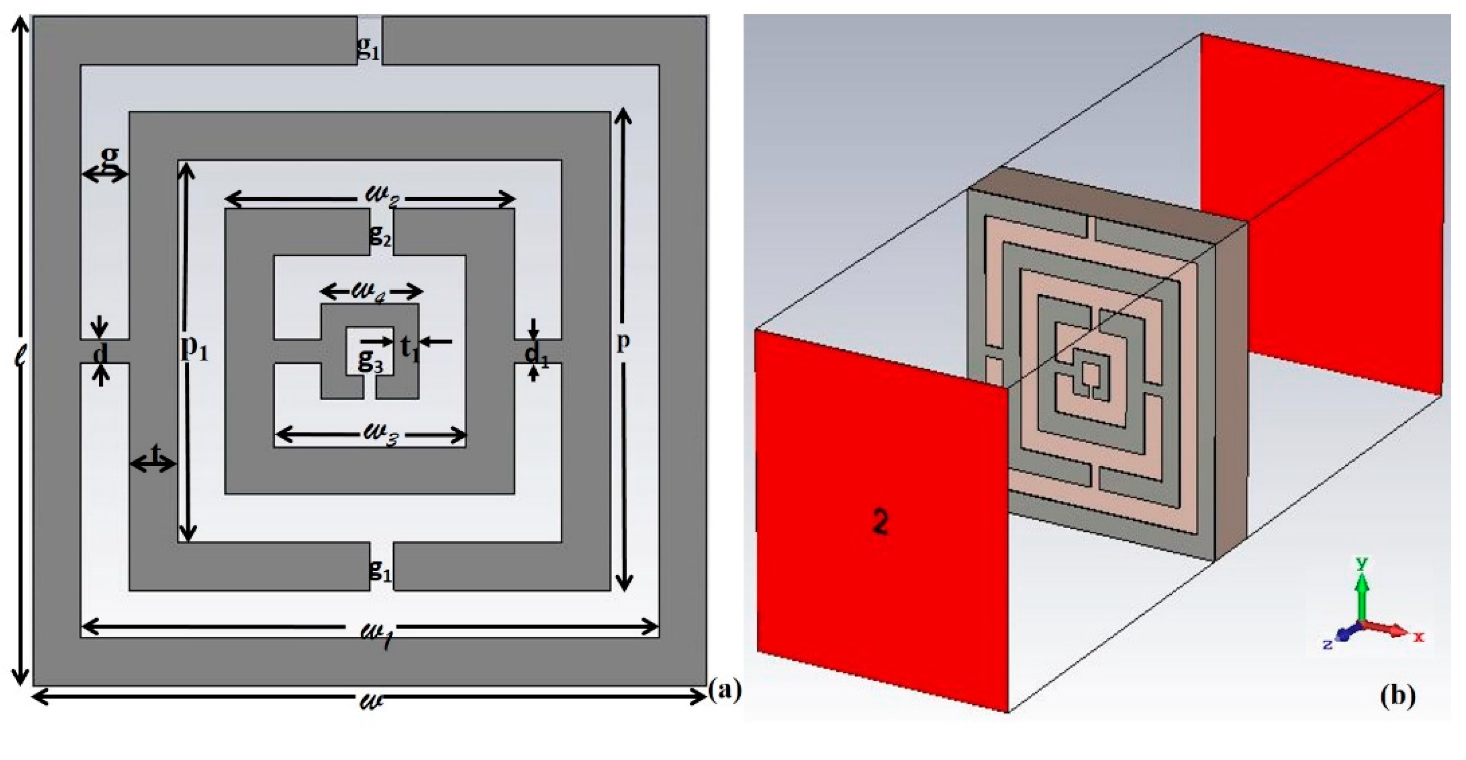
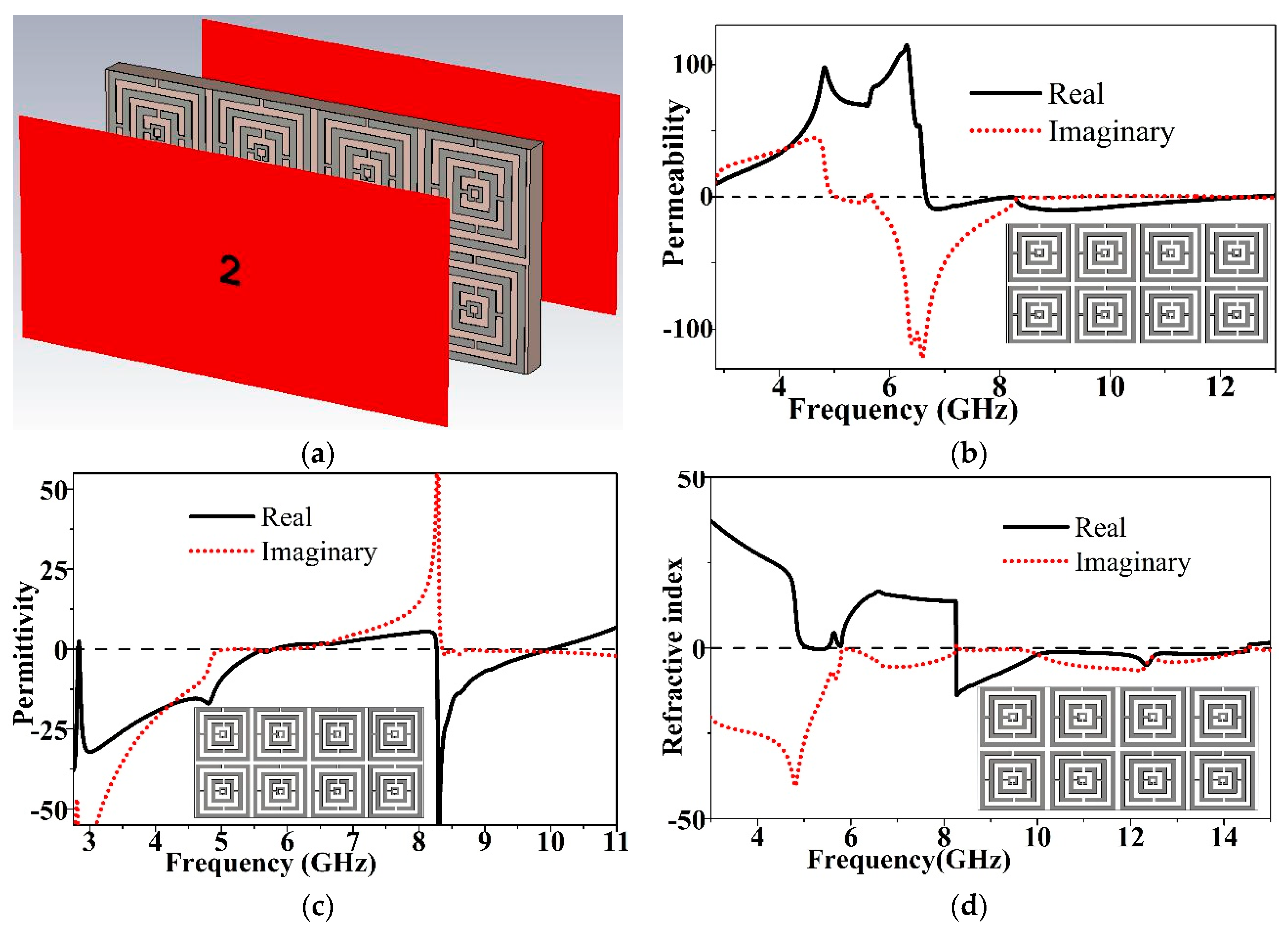
The MTM unit cell has been simulated using a computer simulation technology (CST) microwave studio based on the finite integration technique (FIT). The simulation setup of the proposed MTM unit cell is illustrated in
Figure 1b. The unit cell is placed between two waveguide ports along the negative and positive
z-axis. The perfect electric conductor boundary was placed perpendicular to the
x-axis, whereas the ideal magnetic conductor is perpendicular to the
y-axis. A tetrahedral mesh of frequency domain solver with an adaptive mesh scheme was used for both the array configuration and unit cell investigation. A total of 50 ohms normalized impedance was set with a 2.5–14 GHz operating frequency.
The S-parameters (reflection co-efficient
S11 and transmission co-efficient
S21) for both the elementary item and array structures were studied to understand the electromagnetic characteristics of the proposed MTM unit cell. The electromagnetic properties of MTM depend on the dimensions of the unit cell, and the working wavelength in the media should be larger than that of the unit cell wavelength [
16]. The simulated S-parameters of the unit cell are exported to Math CAD. The
S11 and
S21 of the proposed unit cell is illustrated in
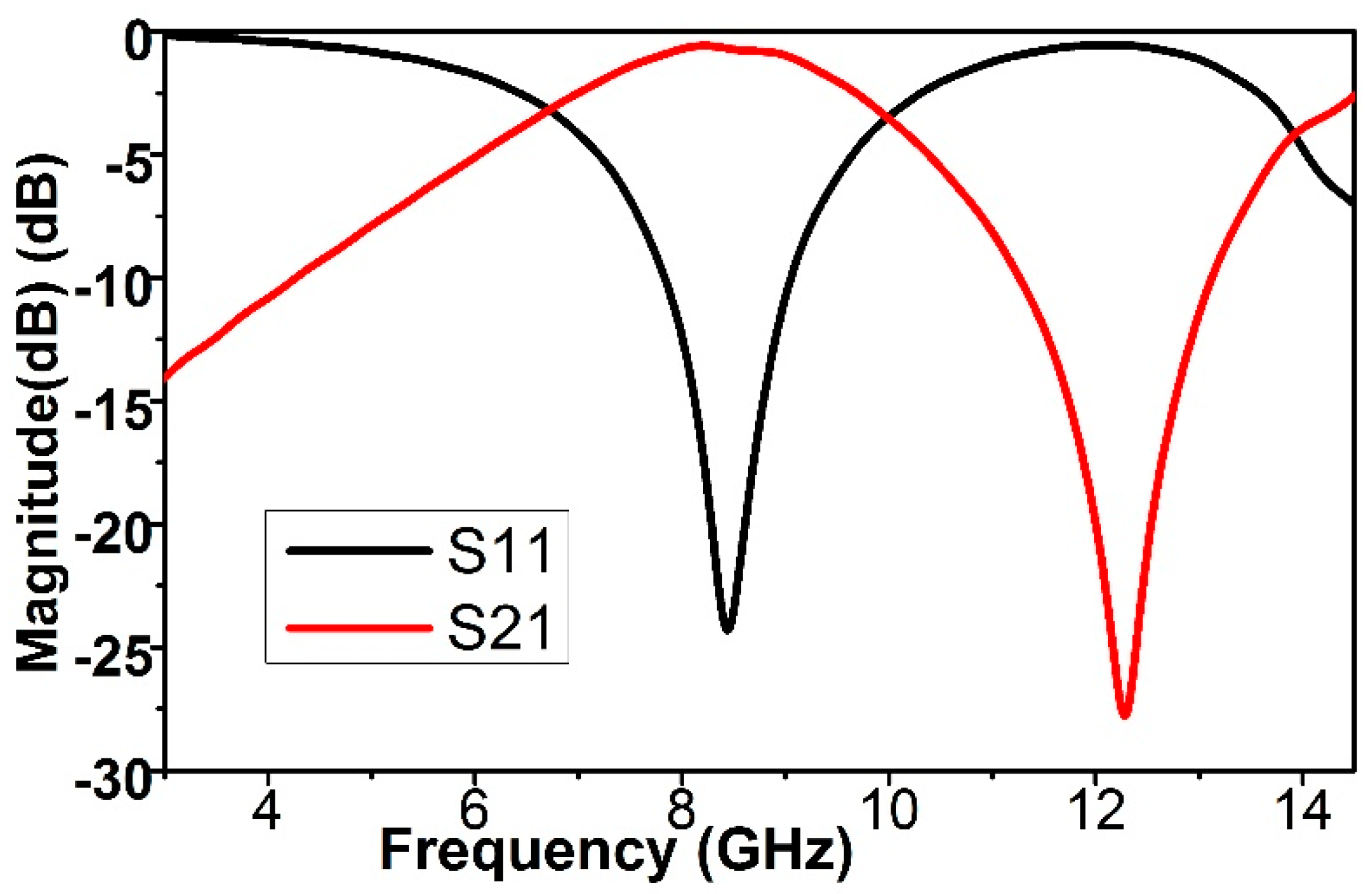
Figure 2. The proposed unit cell is polarization independent and transparent to the transmission peak at 8.4 GHz with a half-power (3-dB) bandwidth of 1.3 GHz denoting a left-handed band. In the transmission co-efficient (
S21), the resonant is at 12.3 GHz. The major findings of the proposed unit cell is the enhancement of the metamaterial magnetic response, from the larger overall current, and self-resonance and overlap responses with respect to conventional SRRs designs. The reflection co-efficient (
Γ) is calculated as:
where
zo is the relative impedance determined as the square root of the ratio of effective permittivity and permeability:
The reflection co-efficient (
S11) and transmission co-efficient (
S21) can be determined as:
By using Nicolson–Ross–Weir approach [
17], the effective parameters such as the relative permittivity (
εr), the permeability (
µr) and refractive index (
ηr) can be retrieve using
S11 and
S21. The calculation is as follows:
where,
, d is slab thickness and
c is the speed of light.
The refractive index (
ηr) can be calculated directly from the permittivity (
εr), the permeability (
µr) using the transmission and reflection co-efficient as:
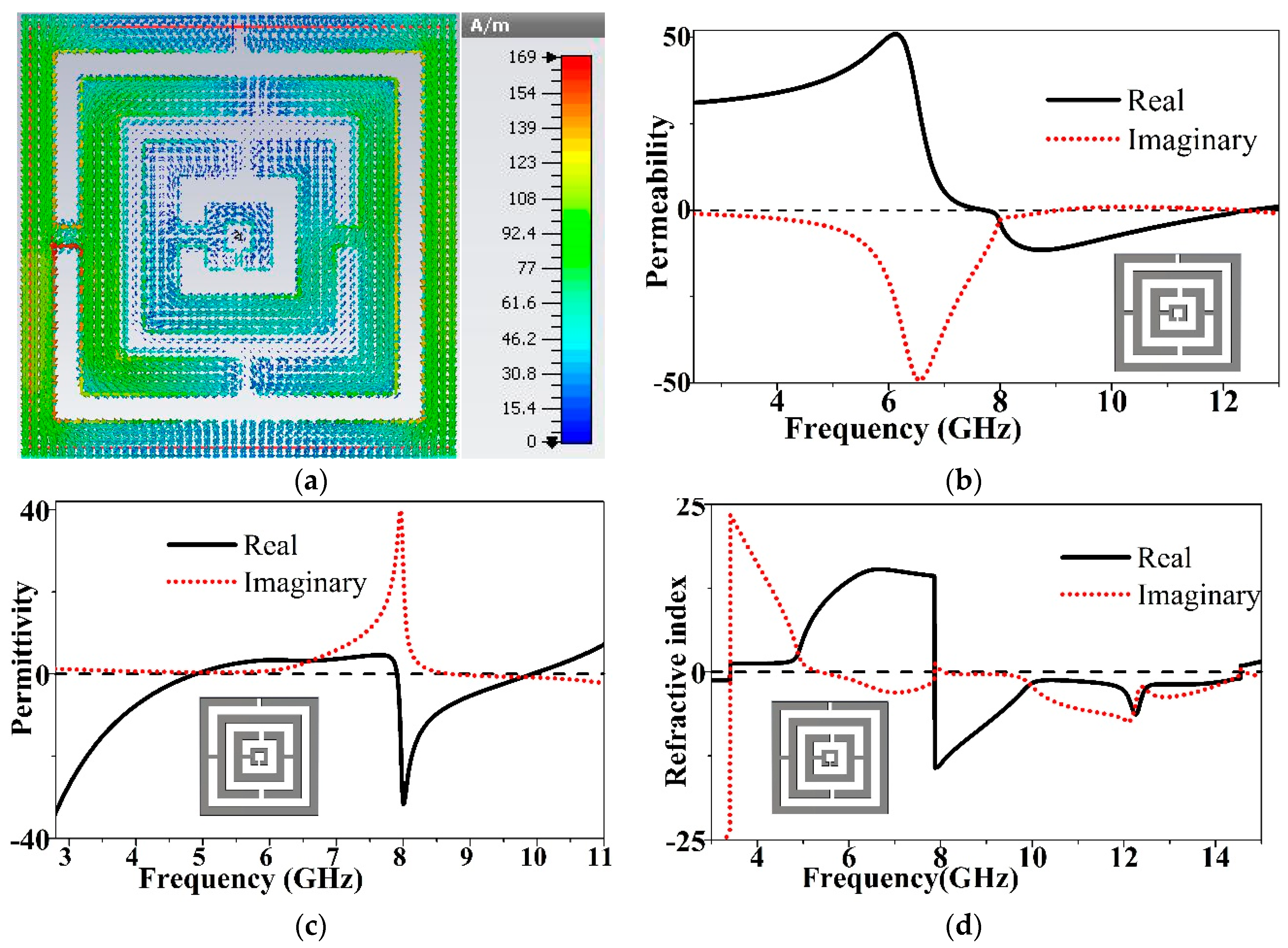
3.1. Elementary Analysis
The electromagnetic properties of the unit cell are retrieved using Equations (1)–(9) provided above, which are calculated using
S11 and
S21.
Figure 3a shows the current density of the proposed LHM unit cell at a frequency of 8.4 GHz. The current flows mostly over the outer stripe. In each stripe, the current flows in the opposite direction due to the modified structure of the SRRs. The opposite current of the inner and outer stripes creates the stop band. From
Figure 3b the negative permeability (µ) of the reported unit cell from 7.9 GHz to 12.3 GHz can be seen. The negative permittivity (ε) of the proposed MTM unit cell from 2.85 GHz to 4.84 GHz and 7.9 GHz to 10.05 GHz is shown in
Figure 3c. The negative refractive index will appear if the permittivity and permeability of a unit cell remain negative simultaneously.
Figure 3d demonstrates the effective refractive index (η) from 7.9 GHz to 14.2 GHz. The permeability, permittivity and refractive index have negative peaks at 7.9 GHz, which represents the proposed unit cell as having negative metamaterial characteristics. From the characteristics, the LHM structures improved remarkably compared to recently-published metamaterials, including negative values over broad band. The tuning of both copper strip rings and the gap between them is used to attain the band gaps around the resonance or unattainable stop band.
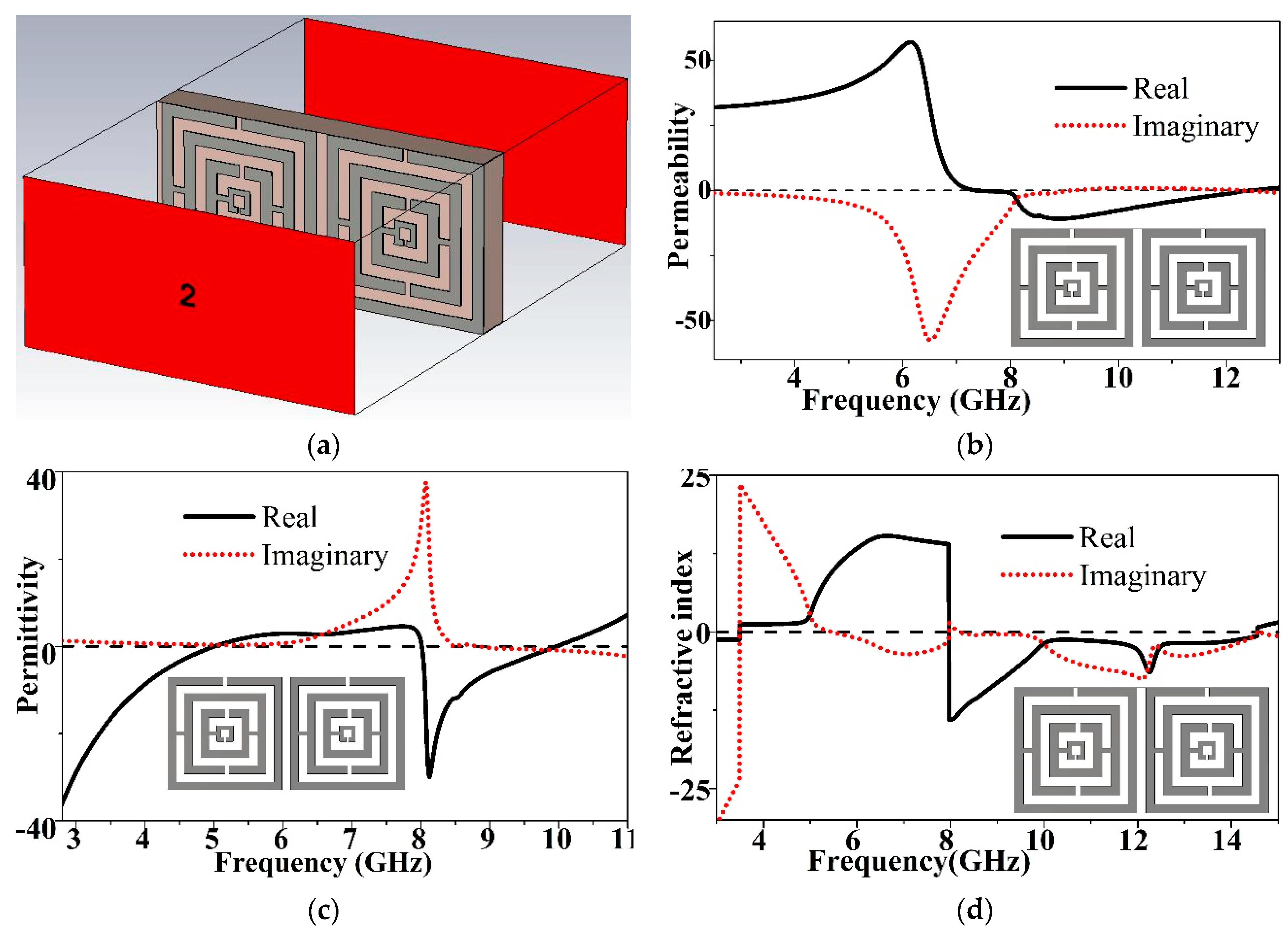
3.2. 1 × 2 Array
The geometry of the 1 × 2 array of the proposed MTM unit cell is shown in
Figure 4a.
Figure 4b shows the magnitude of effective permeability. The frequency range of negative permeability (µ) is from 7.9 GHz to 12.3 GHz. The negative permittivity (ε) is exhibited from 2.8 GHz to 4.85 GHz and 7.985 GHz to 9.986 GHz, as shown in
Figure 4c.
Figure 4d depicts the magnitude of the refractive index over frequency. The negative refractive index (η) is shown from 7.950 GHz to 14.50 GHz, covering a bandwidth of 6.55 GHz. The configuration is an open array and in the region between 7.98 GHz and 9.986 GHz all the electromagnetic properties show negative peaks.
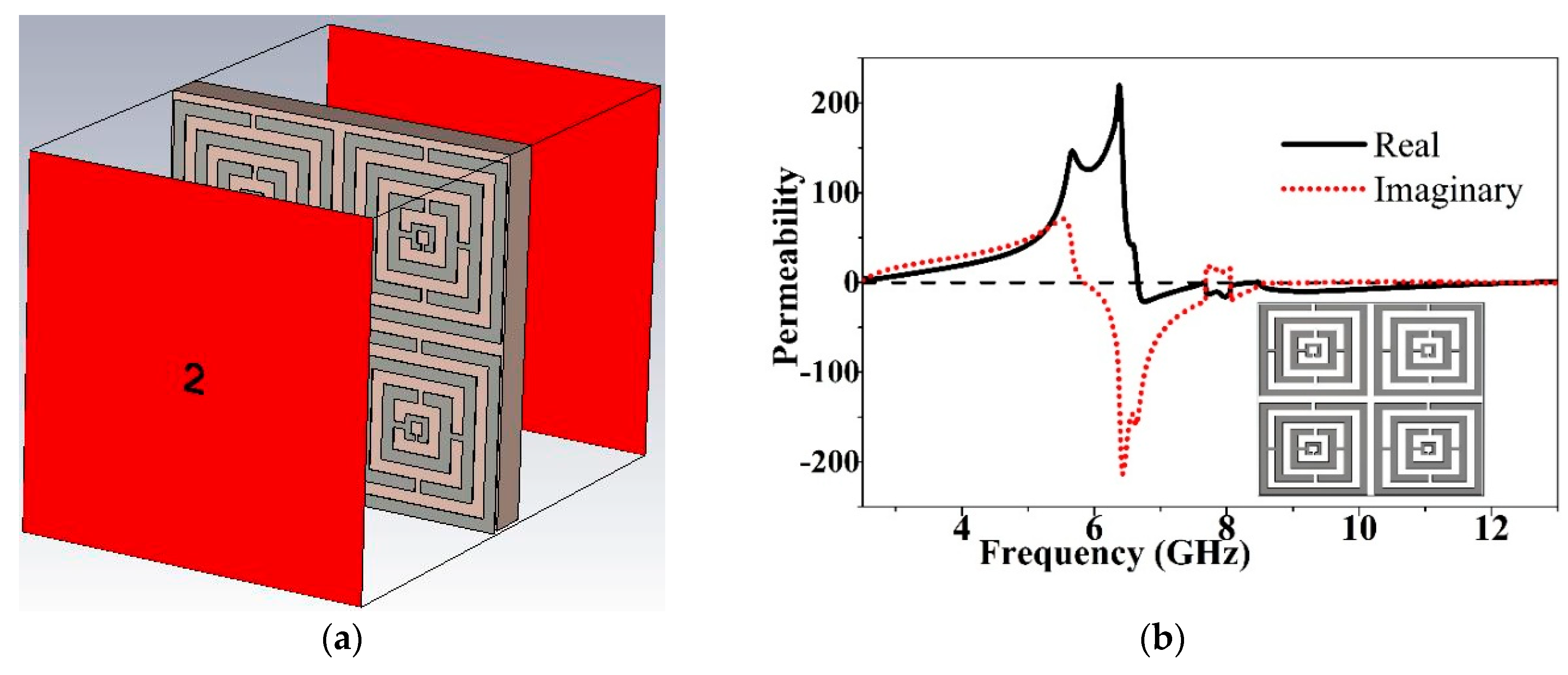
3.3. 2 × 2 Array
The 2 × 2 array configuration of proposed MTM unit cell is shown is
Figure 5a. In the array configuration the unit cells are not connected with each other. The gap between each unit cell remains 0.5 mm on each side. By using the same methodology, the effective parameters are retrieved and shown in
Figure 5b–d. From
Figure 5b, the negative permeability (µ) of this configuration exhibited from 6.65 GHz to 12.70 GHz, covering a bandwidth of more than 6 GHz, can be seen. In
Figure 5c the negative magnitude of permittivity (ε) is from 2.61 GHz to 5.93 GHz, 7.67 GHz to 8.07 GHz and 8.49 GHz to 10.10 GHz. As mentioned earlier, the refractive index will be negative if the permeability and permittivity appear negative concurrently. The refractive index (η) exhibits negative peaks from 6.68 GHz to 8.09 GHz and 8.50 GHz to 14.54 GHz. Moreover, the 2 × 2 array structure shows a negative index metamaterial.
3.4. 2 × 4 Arrays
In
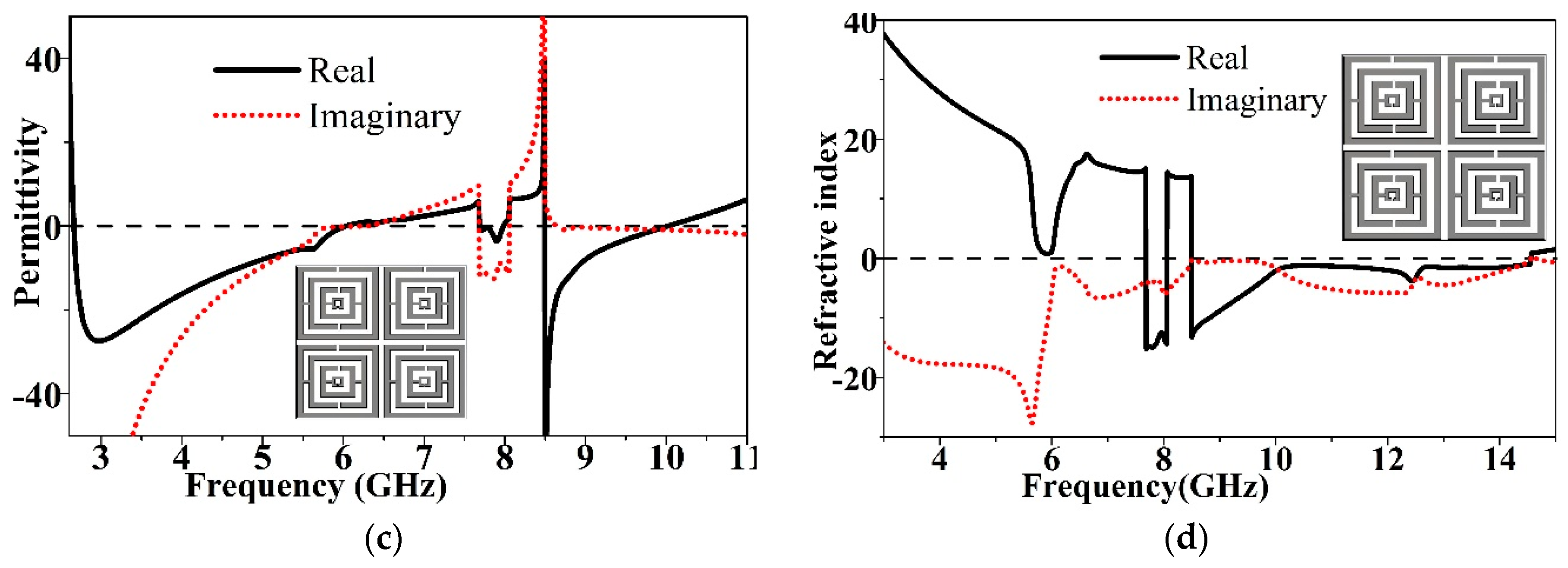
Figure 6, the electromagnetic characteristics of the proposed unit for the 2 × 4 array configuration are demonstrated. Negative permeability (µ) exists from 6.65 GHz to 12.21 GHz, covering 5.56 GHz of the bandwidth shown in
Figure 6b. In
Figure 6c, the magnitude of permittivity (ε) is negative from 2.857 GHz to 5.759 GHz and 8.264 GHz to 9.974 GHz. The real magnitude of the refractive index (η) is depicted in
Figure 6d. The refractive index (η) exhibits negative peaks from 8.258 GHz to 14.533 GHz.
Table 2 summarizes the effective electromagnetic properties of the proposed metamaterial unit cell and different array configurations, such as 1 × 2, 2 × 2 and 2 × 4. From
Table 2 it can be found that the LHM MTM unit cell and array configurations have different resonances in the negative index frequency region. Finally, the proposed unit cell structure shows negative metamaterial characteristics at 8.50 GHz in all the configurations of the 1 × 2, 2 × 2 and 2 × 4 array.
4. Antenna with MTM Structure: Design Approach
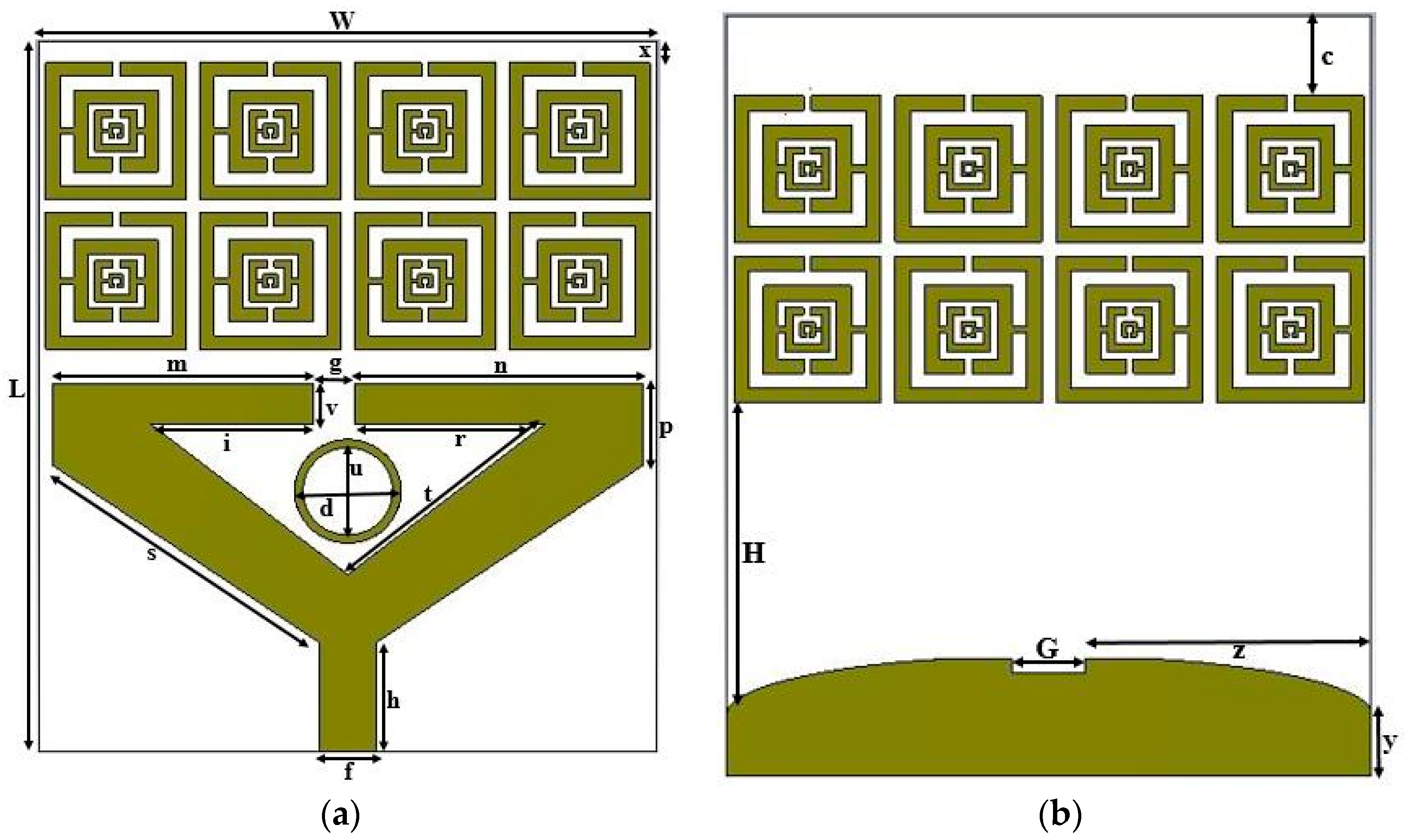
The geometric structure of the proposed antenna based on previously-designed, wide-band, zero-index, metamaterial unit cell is depicted in
Figure 7. The antenna is printed on commonly-used, commercially-available, flame-retardant (FR4) material of 1.6 mm thickness with 4.6 dielectric constants, due to its low cost and convenience for making multilayer printed circuit boards (PCBs). The overall size of the MTM antenna is 22 × 26 mm
2. The radiating patch was designed with a modified triangular stripe line and planar ground plane. The stripe line is not fully connected. There is a gap on the upper side of the triangle, which forms a capacitance and produces a coupling between the electric fields to create electric resonances. A metal-stripe, circular, ring slot with a 3.80 mm outer radius and 3.20 inner radius is placed inside the patch. The metal-stripe, circular ring have a strong effect on the upper frequency to keep the magnitude-of-reflection co-efficient less than −10 dB. By using the metal-stripe, circular, ring structure, the feedline current does not spread out and it helps to remain well-suppressed at a higher frequency. The values of the design parameters are given in
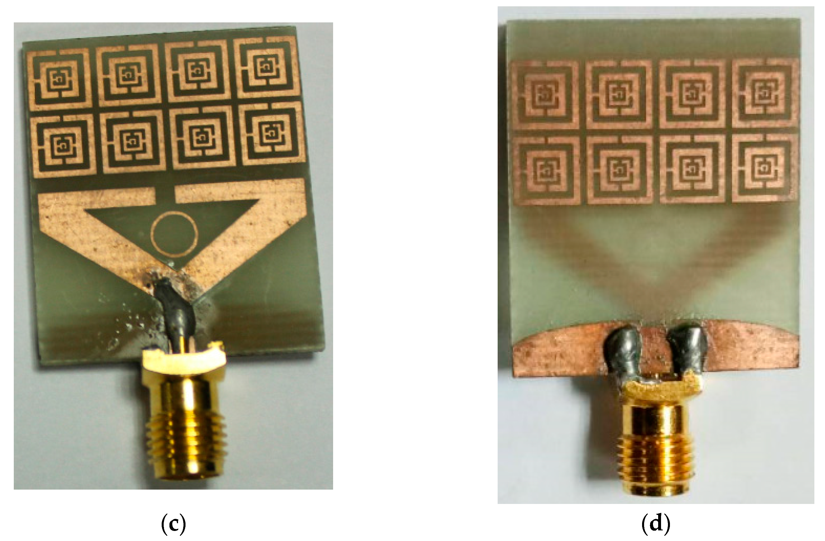
Table 3. A planar MTM pattern (array of 2 × 4) is mounted on both sides of the substrate to enhance the radiation and broaden the working bandwidth. The fabricated prototype of the proposed antenna is shown in
Figure 7c,d. The antenna is fed by a 50 Ω microstrip line situated at centre of the triangular patch. The patterned, radiating patch is coupled with a conducting ground plane back to the substrate. This coupling-patch ground pattern forms a capacitive–inductive equivalent circuit that induces backward wave travels and enhances the radiation in the plane [
11,
14]. This edge-to-edge coupling between the patch and ground helps to create extra radiation over the bandwidth. The array of the MTM unit cell has a strong effect on increasing the electrical length of the antenna both in the lower and higher operating bands, as well as efficiency and gain.
5. MTM Antenna Performance Analysis and Microwave Imaging
The main goal of this MTM antenna design is to exploit the antenna suite for microwave imaging. For microwave imaging, the antenna should have high gain, wider bandwidth, sharp resonant frequency and higher directivity. This is essential to scan deeper tumors inside the breast with high resolution [
18]. MTM (2 × 4) structures are used in both sides of the substrate to produce a smooth radiation profile, minimize back radiation, and improve gain and efficiency compared to conventional microstrip antenna. The antenna radiation performance, directivity and front-to-back ratio are improved by using the phase reflection properties of the MTM structure. The performance characteristics of the MTM antenna have been analysed, studied and optimized using a finite integration technique (FIT)-based computer simulation technology (CST) microwave studio. The accomplishment of the parametric study provides an optimized geometric structure of the proposed antenna which is realized through an in-house PCB laser and circuit prototyping (LPKF) machine to get a physical test model. The measured results were obtained using the Agilent E8362C vector network analyzer (VNA) that covers the range from 10 MHz to 67 GHz and the Satimo near field measurement lab (UKM StarLab) using satimo passive measurement (SPM) and SatEnv software.
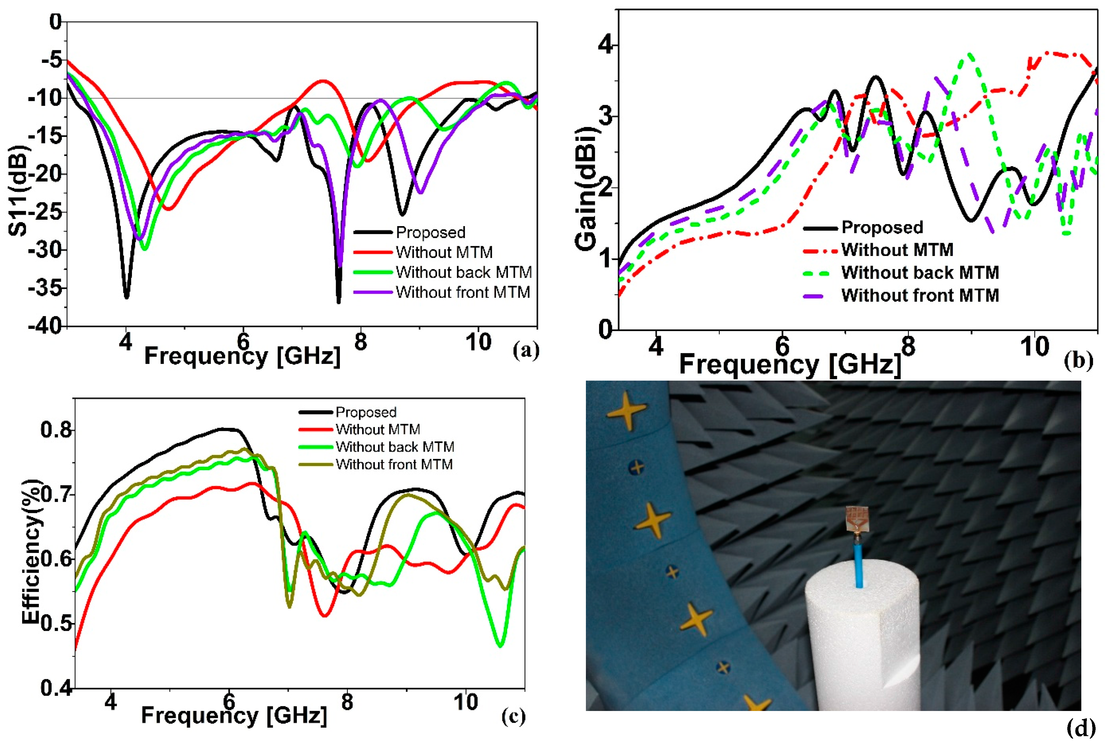
The comparison graph of the simulated reflection coefficient of the proposed antenna is depicted in
Figure 8a. The antenna without MTM has a bandwidth from 3.1 GHz to 9.00 GHz, including a band gap of 6.97 GHz to 7.67 GHz. Through the use of MTM array, the lower band is broadened by about 570 MHz and the upper band is broadened by about 1700 MHz without any band notch. The final bandwidth of the proposed prototype offers a bandwidth of 3.1 GHz to 10.71 GHz, which completely covers the UWB band. The impedance bandwidth of the MTM antenna with a one-sided MTM unit cell array also does not exhibit the UWB range. With front MTM, the bandwidth is from 3.36 GHz to 10.05 GHz, whereas with back MTM it is from 3.28 GHz to 10.15 GHz. The efficiency is also much better when using the MTM array. The overall efficiency is increased by 10% to 20% over the bandwidth after using the MTM array. The proposed prototype offers an average radiation efficiency of more than 70% over the operating band, which is better than the recently published UWB antennas presented in the literature. A moderate gain is found after using MTM array, a gain is an increase in lower frequency, whereas a slight diminution is found in the upper frequency. The simulated efficiency and gain of the proposed antenna is compared in
Figure 8b,c. By using the MTM, the antenna bandwidth increased but no major variation was found in the resonance points. Another remarkable point is noted, namely that a large decrease in the magnitude of return loss is obtained after combining the MTM array structure on the substrate. Without MTM, it mostly decreased to about −28 dB whereas, with MTM it was about −37 dB. One major finding of this study is that there is no gap or mismatch in the entire bandwidth. The enhancement of the antenna is performance proof of the effectiveness of the negative index on the MTM structure and its suitability for MWI applications.
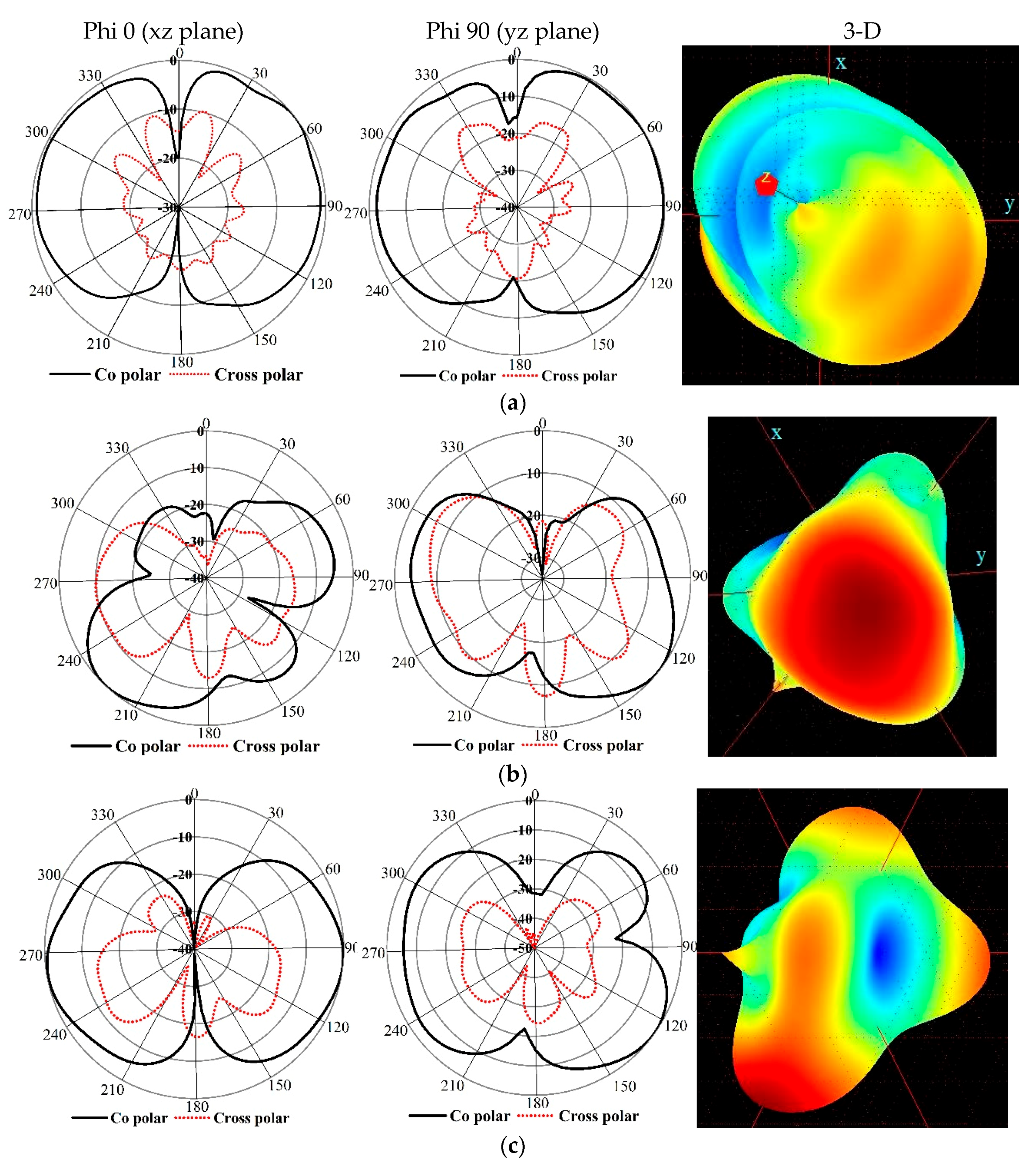
The measured radiation pattern in the major planes for resonant frequencies is depicted in
Figure 9. In the Satimo measurement lab (UKM StarLab), the antenna is measured according to Phi axis rolling and Theta stepping. The measurements are logged in tables of Theta and Phi spherical coordinates. The spherical coordinates relate to the Cartesian axes as follows: XZ Cut is Theta = 0 to 360 & Phi = 0, YZ Cut is Theta = 0 to 360 & Phi = 90 and XY Cut is Theta = 90 & Phi = 0 to 360. The xz-plane (φ = 0) and yz-plane (φ = 90) are considered as the E-plane and H-plane. The near field performance shows that the proposed MTM antenna is directive. The direction of the main lobes is fixed in the endfire direction. Interestingly, the radiations are improved in both the E-plane and the H-plane. The radiation pattern of the co-planar is almost bi-directional, whereas the antenna in co-planar is maximum along the broadside 0°. The directivity is improved at about 5 dB. At a higher frequency, the directivity is shifted due to the introduction of a small back lobe. At a higher frequency, especially at 8.71 GHz, few nulls exist in the radiation pattern due to the excitation of the higher order current mode [
19,
20,
21]. The above discussion proves that the use of the MTM structure reduces the energy leakage of the proposed antenna.
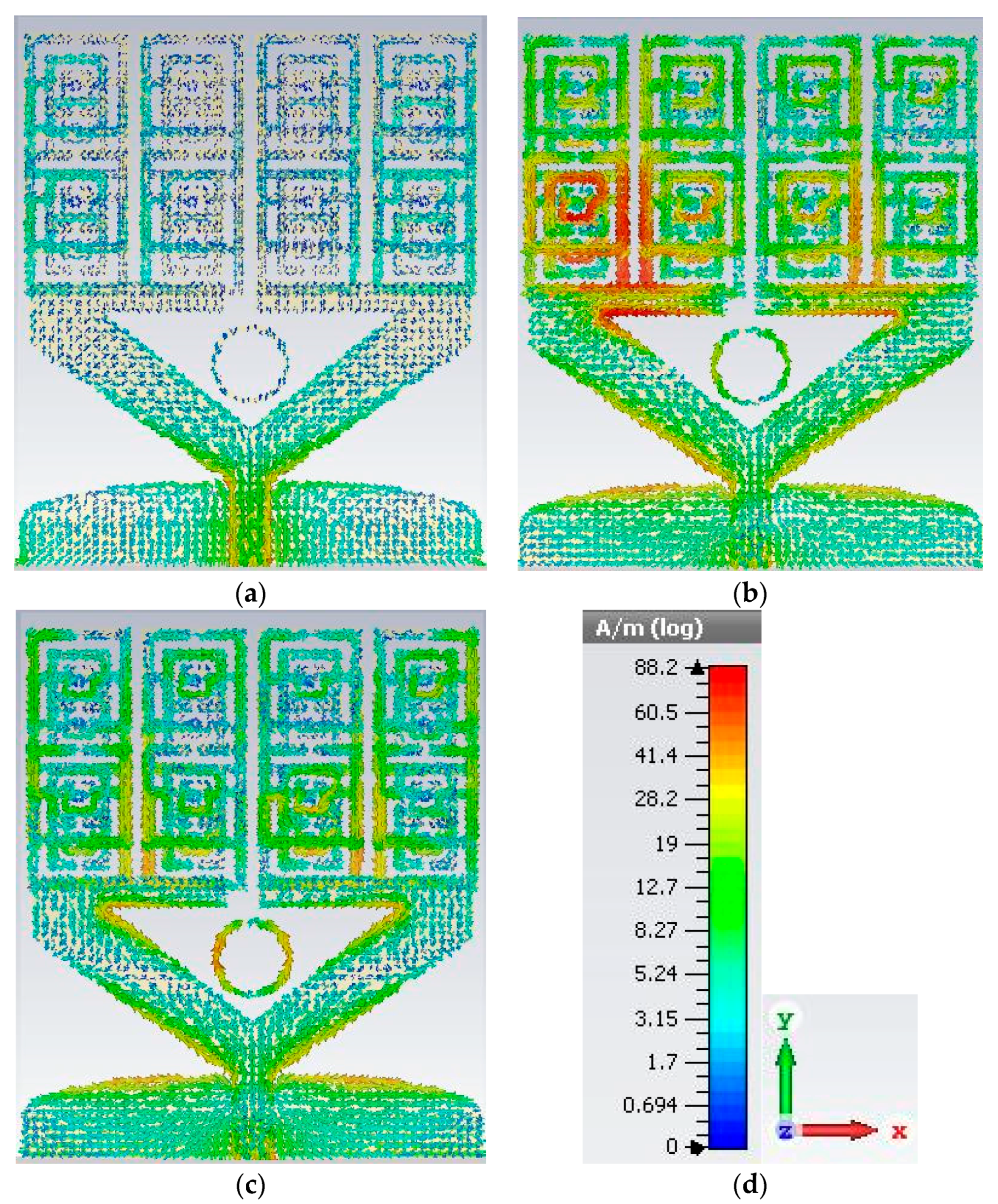
Surface current distributions for resonant frequencies of the proposed MTM antenna are shown in
Figure 10. At a lower frequency, the main current conducting area is around the feed line. At higher frequencies, the current is disseminated around a triangular stripe of patch, with the MTM copper stripe over the substrate and the ground. We observed that by using the MTM structure, the feedline current does not spread out and it is well suppressed by the MTM unit cells. In this case, the feedline current is mostly used to energize the radiating patch. This edge-to-edge coupling between patch and ground helps to create extra radiation over the bandwidth. The MTM structure blocks the surface waves along the vertical cut and assists with improving the mutual coupling between elements.
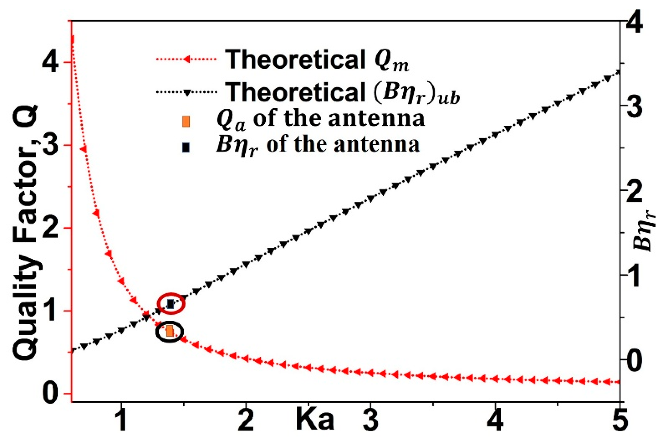
By considering the physical size of the antenna, the minimum quality factor can be obtained from [
22,
23] Q
lb = ηQ, where
, the wave number k = 2π/λ and a is the sphere radius, the smallest sphere that encloses the antenna. The upper band of bandwidth efficiency product
.
Figure 11 shows the Q
m and (Bηr)
ub for the antenna with 70% average efficiency and for different values of ka.
With the value of using the resonant bandwidth of the proposed antenna ka = 1.42. From the curve, it can be noted that for ka = 1.42, the minimum limit of Q
m is 0.68 and limits of (Bηr)
ub is 0.98. The quality factor of the presented antenna is estimated as:
For the maximum allowable voltage standing wave ratio s = 2, the proposed antenna achieved Qa = 0.64 and Bηr = 0.93. From the graph, it can be seen that the resultant value and the attainable values are close to the antenna parameters, which proves that the antenna design is optimum.
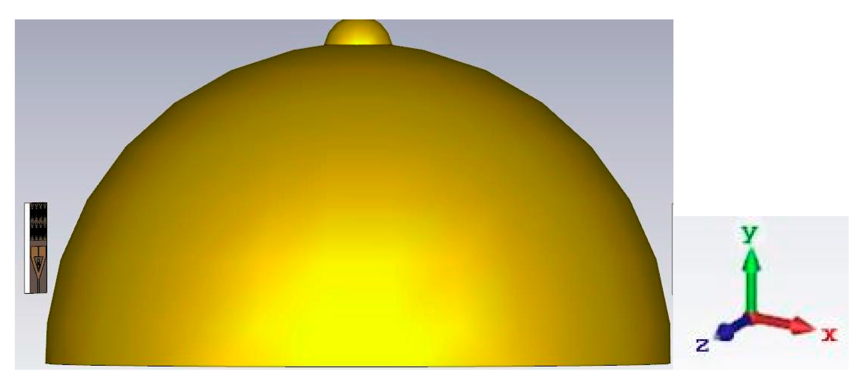
Figure 12 shows the simulation model of a breast with a proposed MTM antenna. The antenna is kept with the breast phantom at a distance of 5 mm and the effects of breast tissues are studied. To study the power coupled to the breast tissue, we compute the near field directivity (NFD) for the proposed MTM antenna. The surfaces of the breast model with a radius of 90 mm and a height of is 100 mm, as shown in
Figure 12. The phantom contains four layers, namely, the skin layer, the breast tissue layer or fat and the normal air layer. The skin layer has the following properties: dielectric constant = 38, thickness = 2.5 mm, and conductivity = 1.49 S/m. The breast tissue layer has a maximum width of 8.75 cm, with conductivity = 0.141 S/m and dielectric constant = 5.14. The work uses real breast phantom and image reconstruction algorithms.
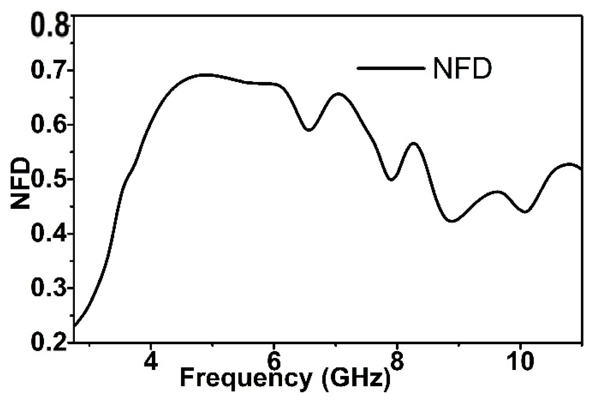
The near field directivity (NFD) factor is computed using the formula in [
24], which is the ratio of radiated power through the front of the antenna (Pf) and the total power radiated through the surface of the breast model (PT).
Figure 13 shows the NFD factor for a proposed side slotted Vivaldi antenna (SSVA). About 65% of the total power is radiated via the front side of the breast tissue.
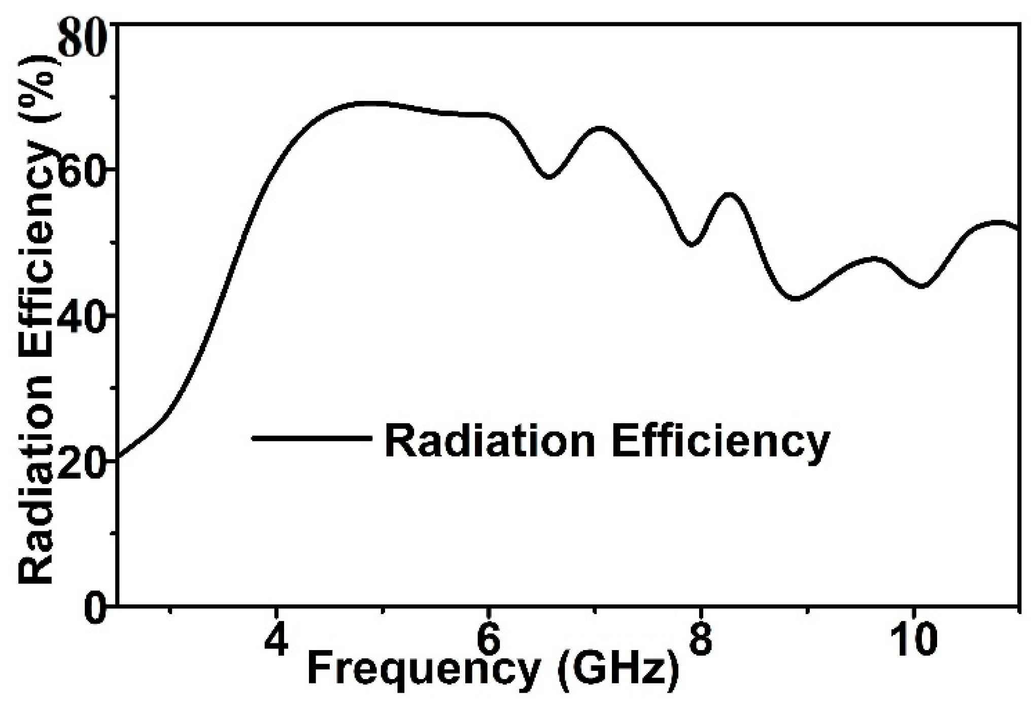
The radiation efficiency of the proposed prototype with the breast model is shown in
Figure 14. The radiation efficiency is defined as
, where Pin is the fed power to the antenna. The radiation efficiency is more than 60% over the bandwidth with breast model. The coupling efficiency is also computed as
, which is the function of radiated power and fed power. The average radiation efficiency over the bandwidth is more than 60%, which indicates that the overall coupling efficiency of the proposed MTM antenna is much better than that of existing, low-directive UWB antennas.

 ,
, 


