An Experimental Platform for Autonomous Bus Development


1
Centre for Automation and Robotics, (CAR) CSIC-UPM, Ctra. Campo Real, km. 0.200, La Poveda, Arganda del Rey, 28500 Madrid, Spain
2
Facultad de Ingeniería Eléctrica, Universidad Tecnológica de Panamá, Panama City 0819, Panama
3
Universidad de Alcalá, Ctra. Madrid-Barcelona, km. 33.6, Alcalá de Henares, 28805 Madrid, Spain
*
Author to whom correspondence should be addressed.
Appl. Sci. 2017, 7(11), 1131; https://doi.org/10.3390/app7111131
Submission received: 26 September 2017
/
Revised: 27 October 2017
/
Accepted: 30 October 2017
/
Published: 2 November 2017
(This article belongs to the Special Issue Road Vehicles Surroundings Supervision: On-Board Sensors and Communications)
Abstract
:Nowadays, with highly developed instrumentation, sensing and actuation technologies, it is possible to foresee an important advance in the field of autonomous and/or semi-autonomous transportation systems. Intelligent Transport Systems (ITS) have been subjected to very active research for many years, and Bus Rapid Transit (BRT) is one area of major interest. Among the most promising transport infrastructures, the articulated bus is an interesting, low cost, high occupancy capacity and friendly option. In this paper, an experimental platform for research on the automatic control of an articulated bus is presented. The aim of the platform is to allow full experimentation in real conditions for testing technological developments and control algorithms. The experimental platform consists of a mobile component (a commercial articulated bus) fully instrumented and a ground test area composed of asphalt roads inside the Consejo Superior de Investigaciones Científicas (CSIC) premises. This paper focuses also on the development of a human machine interface to ease progress in control system evaluation. Some experimental results are presented in order to show the potential of the proposed platform.
1. Introduction
As it is well known, the California Program on Advanced Technology for the Highway (PATH), a collaboration between the Institute of Transportation Studies at the University of California at Berkeley and the California Department of Transportation (Caltrans), with funding provided by Caltrans and the U.S. Department of Transportation, has done pioneering work on Automatic Vehicle Control (AVC) since 1986 and provided an outstanding stream of new ideas, methods and developments [1]. It is worth mentioning also that at Ohio State University (OSU), a program running from 1964–1980 included studies on headway safety policy, longitudinal control, lateral control and highway system operations [2]. Moreover, the interest in the Intelligent Vehicle Highway System (IVHS) was emphasized by the 1973–1979 projects funded by the Ministry of International Trade and Industry (MITI) of Japan [3]. Early considerations concerning safety implications of vehicle automation using the drive-by-wire concept and the driver workload with respect to the transformation from Cruise Control (CC) to Adaptive Cruise Control (ACC) were presented in [4]. More recently, the problems of adaptive cruise control, stop and go [5], as well as the overtaking maneuvers [6] have been investigated, and solutions based on artificial intelligence have been proposed and experimentally tested by researchers of the AUTOPIA Group at the Centre for Automation and Robotics (CAR) of the Consejo Superior de Investigaciones Científicas (CSIC), Spain. In addition to these works, a vehicle of AUTOPIA (Spanish research project) ran driverless 100 km, in 2012, from El Escorial to Arganda del Rey (Madrid). A leading vehicle, which was driven manually, dynamically generated a high accuracy map to be tracked by the fully-autonomous following car. The journey covered a wide range of driving scenarios, including urban zones, secondary roads and highways, in standard traffic conditions (https://www.car.upm-csic.es/autopia/).
In a motivating survey paper [7] published in 2000, a substantial increment of research in intelligent vehicles and their application areas was acknowledged, where sectors of interest and key supporting technologies were considered. Applications related to passenger cars, heavy trucks, bus and public transport applications, as well as special vehicle applications were analyzed, and relevant functionalities/requirements were identified (collision warning, collision avoidance and driver assistance, driver impairment monitoring intelligent speed adaptation, automated operation, industrial automation, military operations).
Nowadays, especially in urban/suburban areas, there is a clear conflict among collective transportation (high occupancy vehicle) and individual transportation, which results in overcrowding that makes transportation uncomfortable, lengthy, polluting and more expensive than needed. This situation decreases substantially the quality of collective transportation services. Because of this general concern, the development of new concepts and technology for urban/suburban transportation is of major importance. In these circumstances, the interest in Intelligent Transportation Systems (ITS) and Intelligent Vehicles (IV) is increasing because the wide range of possible applications [8].
Among several current developments for urban/suburban transportation, the concepts of Light Rail or Light Rail Transit (LRT) and Bus Rapid Transit (BRT) are some of the most attractive. LRT is a kind of urban public transport using rolling stock quite similar to a tramway, but operating at a higher capacity, while BRT aims to provide a high-quality bus-based transit system with the main advantages of being a flexible and cost-effective urban mobility transit system [9,10]. Both systems operate in segregated paths, and while LRT bear a resemblance to trams, the BRT is essentially characterized by using public transportation vehicles on tires (buses). Furthermore, both systems require a strong support from Intelligent Transportation System (ITS) elements, this aspect being more critical to BRT, which, in the end, has the intrinsic possibility of reaching the state of a truly autonomous system. The Institute of Transportation & Development Policy (ITDP) [11] defines BRT as “a high-quality bus-based transit system that delivers fast, comfortable and cost-effective urban mobility through the provision of segregated right-of-way infrastructure, rapid and frequent operations, and excellence in marketing and customer service”. The BRT goal is to combine the capacity and speed of a metro with the flexibility, lower cost and simplicity of a bus system. BRT systems come in many shapes and forms. However, they all aim, to varying degrees, to mimic the high-capacity, high-performance characteristics of urban rail at a much lower price [12]. According to one study, this reduction can be as much as 4–20-times less than Light Rail Transit (LRT) and 10–100-times less than metro rail systems [13]. BRT uses buses on a wide variety of right-of-ways, including mixed traffic, dedicated lanes on surface streets and busways separated from traffic. In fact, BRT has a greater potential for innovation, and it could be considered as the evolution of present collective transportation systems.
Moreover, the added value provided by the latest advances in control, artificial perception and Information and Communication Technologies (ICT) might facilitate the development of new concepts enabling the creation in the near future of more flexible, fast, reliable, economic and efficient BRT systems of wider and safer use in populated areas [14]. In this regard, an interesting analysis has been released [10] reporting the full picture of the successful dissemination of BRT systems in several Latin America cities, providing the additional encouraging side-effect of environmental conditions’ enhancement. Some BRT systems incorporated guidance (mechanical, optical and magnetic) to increase speed in narrow corridors, which also implies better safety and the possibility of precision docking [9], and this is why BRT could be considered as an intermediate step from classical urban transport (conventional bus services) to fully-autonomous systems [8]. Within this context, the relevance of autonomous guidance in urban transportation targeting improvement of ITS efficiency has been recognized by several authors [8,15].
The advancement of ITS technology takes advantage of previous and parallel research on Autonomous Guided Vehicles (AGVs) and mobile robots [16]. A theoretical contribution to the automatic steering of a city bus was presented in [17], where two different approaches, linear and nonlinear controllers, were compared. The works related to the kinematic and dynamic models of wheeled mobile robots [18] have been important to understand modelling and therefore to set up the grounds for motion planning and control. For example, in [19], the implementation of intelligent and stable fuzzy Proportional Derivative-Proportional Integral (PD-PI) controllers for steering and speed control of an AGV consisting of an electrically-powered golf car suitably modified for autonomous navigation and control was reported. In [20] active steering under model predictive control was researched. In [21], a small electric mini-bus was used to demonstrate the autonomous driving capability and obstacle avoidance using GPS for localization and LIDAR for environment recognition.
Lateral vehicle control [22] is one major issue that has been studied because of its relevance [23], both for warning about lateral vehicle displacement and possible automated intervening in manual driving [24], as well as for full automation, as was shown in the California PATH program [25] and more recently in the DARPA Urban Challenge 2007. In this competition, Caltech contributed with a highly modified Ford E-350 van, nicknamed Alice [26,27], and the Team AnnieWAY demonstrated the results of the Cognitive Automobiles Project [28], an autonomous vehicle that is capable of driving through urban scenarios. Another very relevant and cited contribution in the field was offered by [29], where a prototype nicknamed Babieca (a modified Citroen Berlingo), equipped with a color camera combined with DGPS and on-board controls, allowed lateral and orientation position of the ego-vehicle with regard to the center of the lane, so steering an autonomous vehicle using vision. For lateral control and guidance, the use of magnetic markers on the floor was thoroughly investigated [30,31], and also, the fusion of magnetic markers with encoders has been considered [32]. Significant works on lateral control of heavy-duty vehicles like tractor semitrailers have been produced by the PATH program, implementing nonlinear and adaptive controllers for lateral control of heavy vehicles and presenting an experimental comparative study [33,34,35]. Other relevant problems for vehicle automation have been investigated, and, in particular, those related to control systems have received ample consideration: nonlinear control [36,37], observation of lateral vehicle dynamics [38], external disturbance estimation [39], driver assistance systems based on artificial potential fields [40] and fault-tolerant lateral control for heavy vehicles [41].
While lateral control aims to keep the vehicle at the minimum departure distance from the required path, the longitudinal control [42,43] mission is to properly control the vehicle advance along the desired trajectory, and, to achieve this, a number of critical adaptations need to be implemented. The main issues are start/stop, acceleration and deceleration, velocity control, obstacle detection/avoidance [43] and several others related to the safety of the overall operation [44]. From another side, it is important also to consider that for improved accuracy and reliability of autonomous vehicles’ lateral and longitudinal controllers should be integrated because there is a coupling between steering and velocity actions, and the cross-effects of each one on the other need to be taken into account [45]. This is especially relevant when increasing the speed of operation, in platoon formation, and in variable road and vehicle conditions (slippage, cornering, tire traction forces, etc.).
An interesting work regarding automatic steering control based on how drivers steer has been performed by using the data of drivers’ steering obtained through a number of experiments, showing that drivers in effect execute a naturally robust controller that allows high-gain corrections and is insensitive to variations in vehicle dynamics and speeds [46]. This controller has been implemented and validated on an 18.3 m articulated bus for revenue service [47].
Having examined briefly the major components that could be needed to achieve autonomous vehicle driving, it is worth mentioning that there is a great interest in the development of more complex strategies like those regarding cooperative autonomous driving [48] aiming to obtain intelligent vehicles that could share roads and streets [49,50,51]. More recently and regarding bus automation, a small electric Cyberbus was used to demonstrate a parametric-based path generation algorithm for roundabouts [52]. Other related works have been concentrated on automated parking [53]. It is also worth mentioning the works using artificial intelligence methods based on fuzzy logic to control autonomous vehicles [54,55,56] and the latest developments regarding traffic sign detection [57] and an automatic system to detect distraction and drowsiness in drivers [58].
In this paper, an experimental platform for research on the automatic control of an articulated bus is presented [14,15]. The aim of the platform is to allow full experimentation in real conditions for testing technological developments and control algorithms. The experimental platform consists of a mobile unit (a commercial articulated bus, Volvo B10M-ART-RA-IN) fully instrumented and a ground test area composed of asphalt roads inside CSIC’s premises. This paper focuses also on the development of an HMI to ease progress in the control system evaluation. Some experimental results are also presented in order to show the potential of the proposed experimental platform.
The paper is structured as follows: Section 2 presents an overview of the experimental platform for the autonomous bus development with details about its instrumentation and the control architecture; Section 3 is devoted to the discussion of the longitudinal and lateral control approaches, as well as showing some experimental results. The paper is completed with the main conclusions, in Section 4.
2. Materials and Methods
2.1. Experimental Platform Overview
The purpose of the experimental platform is to provide a reliable base to carry out research and feasibility studies on automatic control of vehicles of large dimensions. Figure 1 shows the main elements of the experimental platform setup: (a) Volvo B10M-ART-RA-IN articulated bus (18 m in length); (b) private inner road facility located at CSIC’s premises in Arganda del Rey (Madrid), with a total length of 385 m. This experimental road has been designed to contain “enough difficult” curvature sections to permit experimentation in demanding situations. Figure 1c shows an analysis of a possible bus trajectory in one section of the path.
Research on autonomous bus control requires deploying multiple sensors and actuators so that they can be used for both monitoring and control. Furthermore, a control system of this kind involves many variables to analyze and monitor during the testing period of the system and also during the various stages of implementation and demonstration. Therefore, it is of considerable importance to organize a robust observation and acquisition information architecture to gather the sensor signals that are set up in the system. The analysis and interpretation of those variables will benefit the design and the comparison of the different control strategies to be implemented for the automation of the articulated bus. Additionally, experimentation with transport systems of large dimensions requires special care for safety, and this requires knowing the state of the vehicle at all times. This information must be known to both the people who go on board the vehicle and to those working at different points of the test facilities. The electronic instrumentation system includes the elements shown in Table 1. In Figure 2, some sensors are shown during the operating tests carried out in the laboratory.
2.2. Velocity Control
The bus velocity control aiming for longitudinal control is performed in the on-board computer by means of two main actions: (1) using an I/O board electronically connected with the bus electronics, where the desired reference advance velocity (throttle) is sent to the bus engine; (2) using the aforementioned I/O board for sending a brake reference signal to the DC motor driver that mechanically controls the brake (pedal) position.
In more detail, and for greater flexibility in the experimental development, the velocity control can be achieved in three ways: (1) the control computer sends the throttle commands to the bus potentiometer that regulates the bus’s own throttle control system; (2) one additional potentiometer is installed near the driver’s seat and can be used manually to alter the computer command; (3) the driver, if seated, can use the throttle pedal to change the commanded velocity directly.
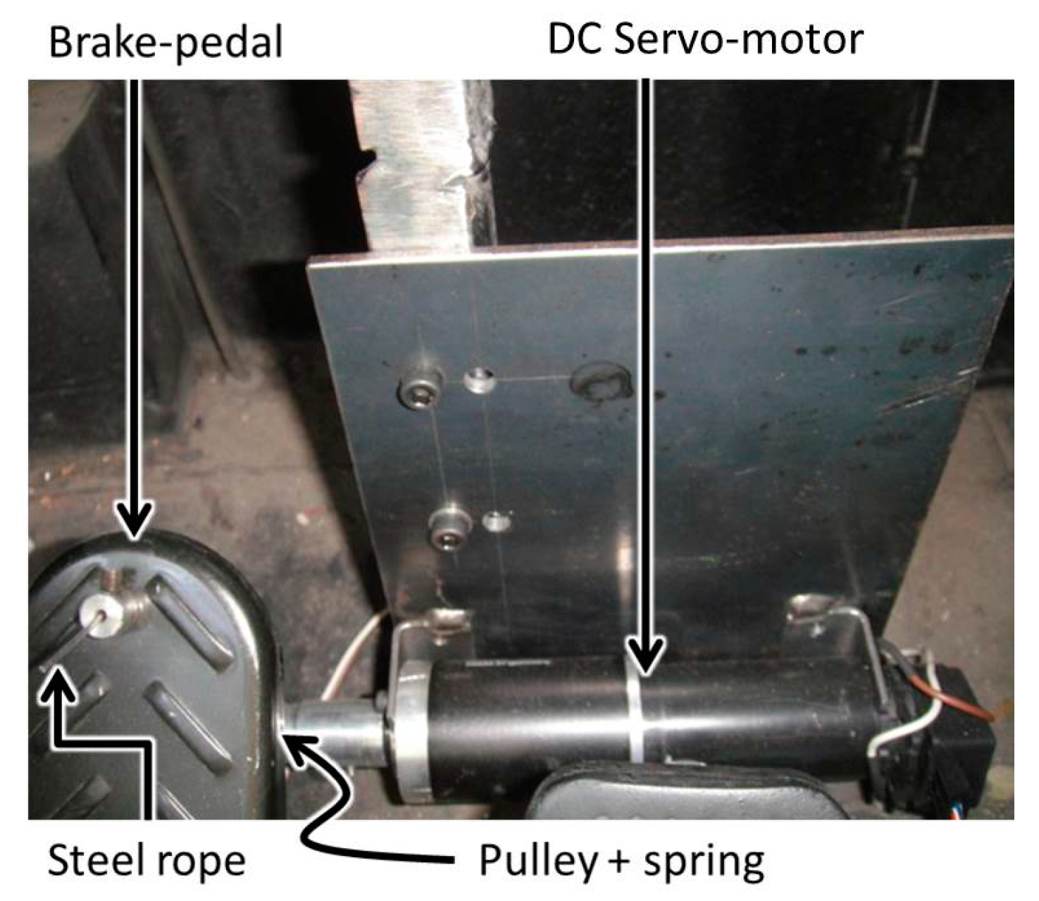
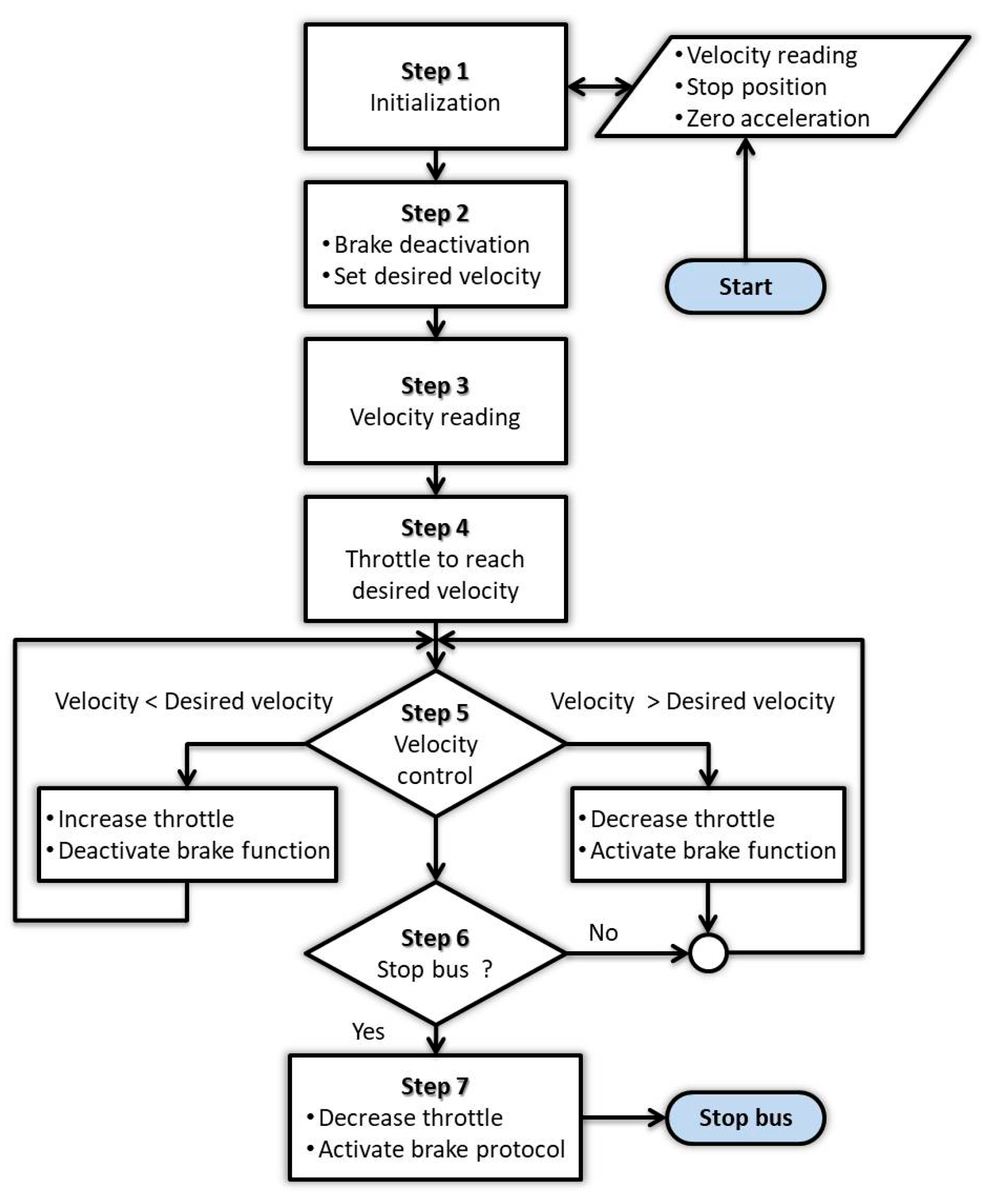
The implemented brake control system consists of a 24-volt DC motor (70 watts) with a gearbox (74:1) and encoder and a pulley with a steel cable whose free end is connected mechanically to the brake pedal (Figure 3). This system works under digital PID closed-loop control receiving the desired reference velocity from the high level control system and comparing it with the actual velocity (provided by different sensors like encoders installed in the bus wheels or others). This system is very useful in practice, not only to stop the vehicle, but especially to regulate, working in combination with the throttle control, the bus velocity according to the desired values. There is an additional advantage consisting of the automatic regulation of the velocity independently of the road slope (positive or negative). Figure 4 shows the flowchart for the velocity control.
2.3. Steering Control
The steering of the articulated bus aiming for lateral control has been achieved by incorporating a 24-volt DC motor (150 watts) with a gear reduction box (74:1) and an incremental optical encoder (2000 ppr) coupled to the steering wheel axis through a 1:1 toothed gear (Figure 5). Both the DC motor and gearbox were calculated to deliver the required torque to the axis of the bus steering wheel. The optical encoder provides the angular steering wheel value to the PID digital controller in charge of the lateral control. Figure 5 serves to illustrate this assembly.
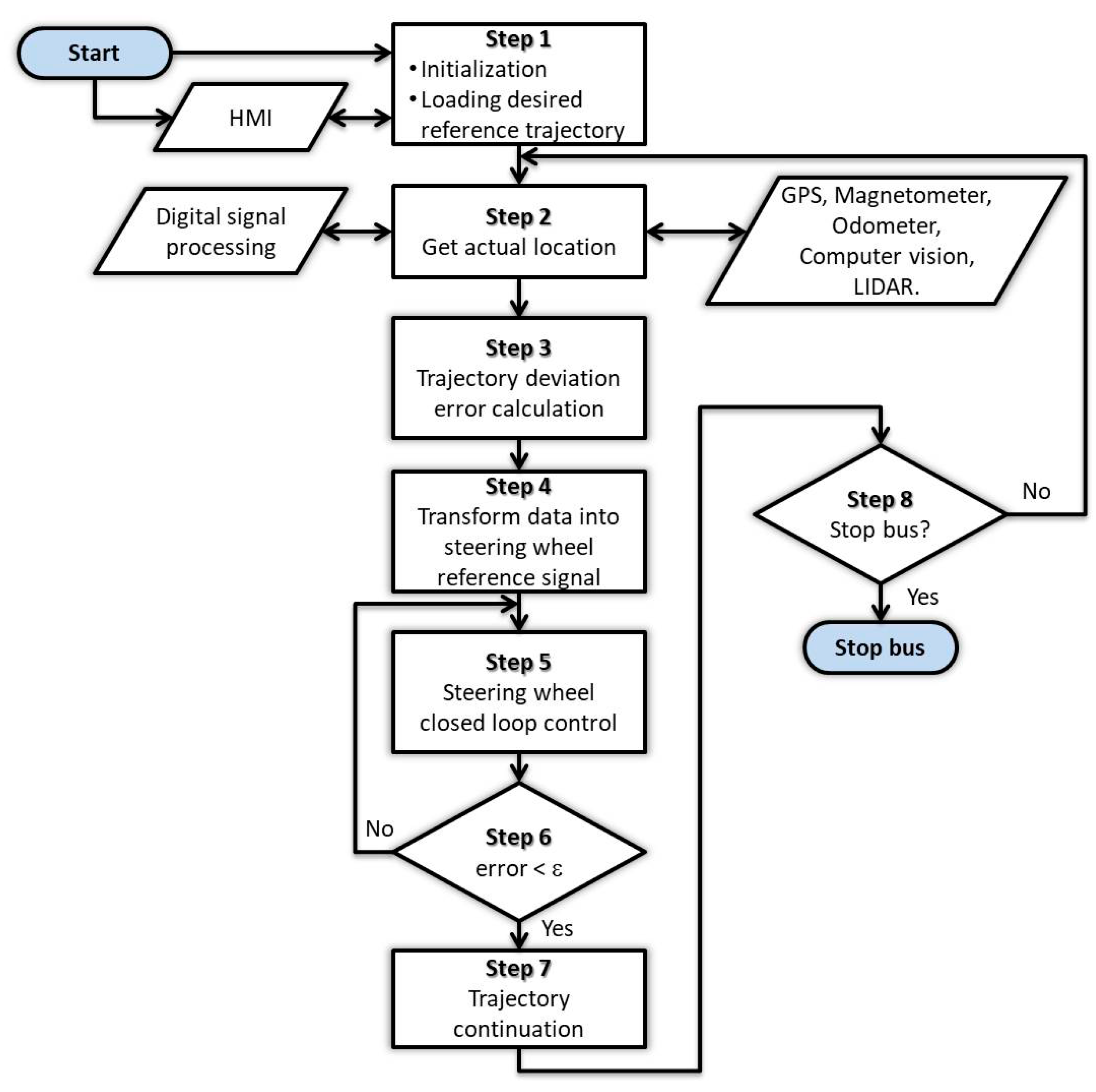
The steering control system has been designed to allow input from different location information sources, the idea being to permit the exploration of using different sensors to assess the accomplishment of the desired trajectory for the bus. Moreover, as will be explained in more detail in Section 2.6, when dealing with the control architecture, it will be possible to employ several location sensors: GPS, magnetometer systems for magnetic markers’ detection (hidden magnets buried along the desired bus path), odometer, computer vision and LIDAR. Depending on the chosen sensor, a processing algorithm is needed to transform the supplied data into a reference command signal to the steering control system so that the bus will be able to track the desired trajectory. The experimental setup prepared for this research has been configured to permit the simultaneous use of different, heterogeneous, location sensors, and so, an intelligent combination of sensors (i.e., GPS and computer vision) could be chosen to investigate their complementarity and advantages, normally requiring additional data fusion algorithms.
Regarding the desired trajectory, there are many possible ways to determine it, like manually driving the bus and recording the GPS coordinates, navigation with computer vision or LIDAR and logging data with the odometer or GPS, or just in real time with a magnetometers array looking for (detecting) hidden magnets on the path, among others. In Figure 6, the flowchart for the steering control implemented in this work is shown.
2.4. Obstacle Detection
The development of a practical obstacle detection and safety system for vehicles often involves working in complex scenarios. The experimental platform includes two LIDAR systems, the LMS-221 and LMS-291. Both lasers (electronic device based) provide non-contact measurement of the surrounding environment in the form of a cloud of 2D data points. This experimental platform is completed by a catadioptric omnidirectional stereovision system [59,60], which together with the LIDAR make up a reliable obstacle detection system, and it could be useful for other related tasks. The chosen system is designed to work in harsh conditions (rain, snow, fog, warm or cold weather), mainly using the LMS-221. Some of the applications are: objects’ measurement, positioning with respect to other vehicles and obstacle detection (in particular, pedestrian detection). The LIDAR can be used also to calculate the slope of the road, which can help the control system with additional useful information.
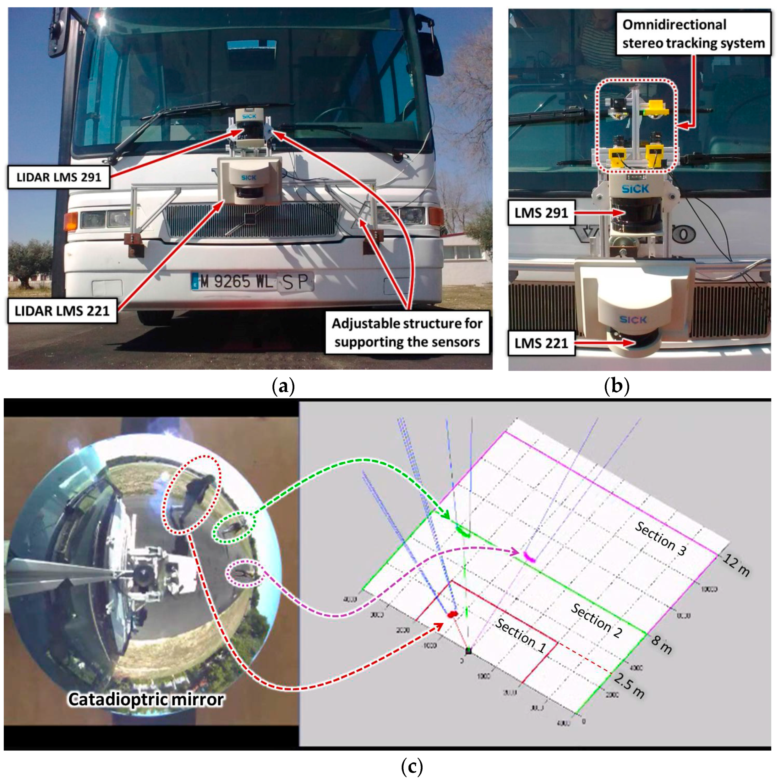
Figure 7a shows the LIDAR system installed at the bus front, at a height of 930 mm and 1490 mm above the soil plane. The supporting structure is mechanically adjustable to permit several angles of inclination for these sensors. Figure 7b shows the omnidirectional stereo tracking system, which has been attached to the LIDAR system, with the aim of being used in some experimental trials to evaluate the efficiency of the obstacle detection process. With a range of angular action of 180 degrees and its real-time capabilities, the LIDAR can be used to detect animate or inanimate objects. This system can be used for the bus’s own safety and that of its passengers in the case of finding inanimate obstacles close to the bus front and/or for the safety of a moving object crossing the bus path.
In order to test the capabilities of the experimental vehicle, a simplified object classification method is proposed, where the sensory system classifies the sensed scenario into two groups: sections with obstacles and safe path lane areas. The combination of LIDAR systems and cameras is widely used because of its complementary capabilities, and several techniques have been proposed for data fusion [61,62]. In these works, a standard chessboard was utilized to calculate the transformation matrix between sensors. To compute obstacle detection, the data measurements from lasers are split into several subsets/segments by using the jump distance condition. Then, the subsets are classified into one of the two-defined groups by analyzing the geometrical properties of the segments such as the average deviations from the median and the jump distance to each succeeding segment, as described in [63]. The laser segments detected as obstacles are considered as inputs for computing disparities of the regions of interest of the omnidirectional images.
Obstacles detected along the vehicle trajectory are sorted into the three warning sections (see Figure 7c). This classification relies on the distance and position between obstacles and the vehicle. When objects are placed in Section 3 or in Section 2, the vehicle decreases its velocity to 40% or 80%, respectively. In that way, a safety distance of 8–12 m could be achieved. However, when an object is detected within Section 1 (2.5 m), a full stop is carried out. Movement is resumed automatically when the obstacle disappears. Due to the vehicle characteristics, an avoidance maneuver was not considered. Many experimental tests were carried out with success.
2.5. Software and HMI
To speed-up the research of the automatic control system for the articulated bus and to monitor its performance during the experiments, it is convenient to incorporate a Human Machine Interface (HMI). In this section the main characteristics of this HMI will be described. The environmental constraints are considered a key point for designing this HMI. First, the mobile system is a long vehicle, with multiple variables, working in tough conditions under a real-time operation system. Because it must cover large displacements, the operator’s safety (and comfort whenever possible) is a priority. The HMI must display comprehensible and significant information, and the real-time requirements must be satisfied.
The main purpose of the HMI is to establish friendly, remote and intuitive communications between the vehicle and the people who operate it, and it also includes an adaptable and open configuration. Thus, the HMI contains the following properties:
- Multiple sensors and variables can be visualized; two and three dimensions are considered for some sensors.
- Real-time visualization of the information.
- Multiple and simultaneous clients connection can be accepted.
- Adaptable according to the requirements/configuration of every client.
- Data storage for every testing session.
- The old session can be visualized: offline mode.
- The TCP/IP communication protocol has been used to communicate between the vehicle and the users (researchers).
The HMI client-server architecture is based on a server running on-board the vehicle, operated on the RTOS (real-time operating system) named QNX® [64] and a client that can run on any PC and that has been developed in MATLAB® [65]. A simultaneous connection of several clients, from i = 1…n, is possible, where each client is denoted as the i-client. Figure 8 shows the general diagram of the remote system communication between the server and the n-clients.
The server consists of a “Clients Manager”, whose purpose is to create and control the communication channels with every connected i-client. It also has to handle the clients’ requests considering the clients’ initial configuration. In order to communicate between the server and the main controller, an interface has been created called “data_devices Manager”, which is in charge of acquiring the information of the active devices and variables of the system.
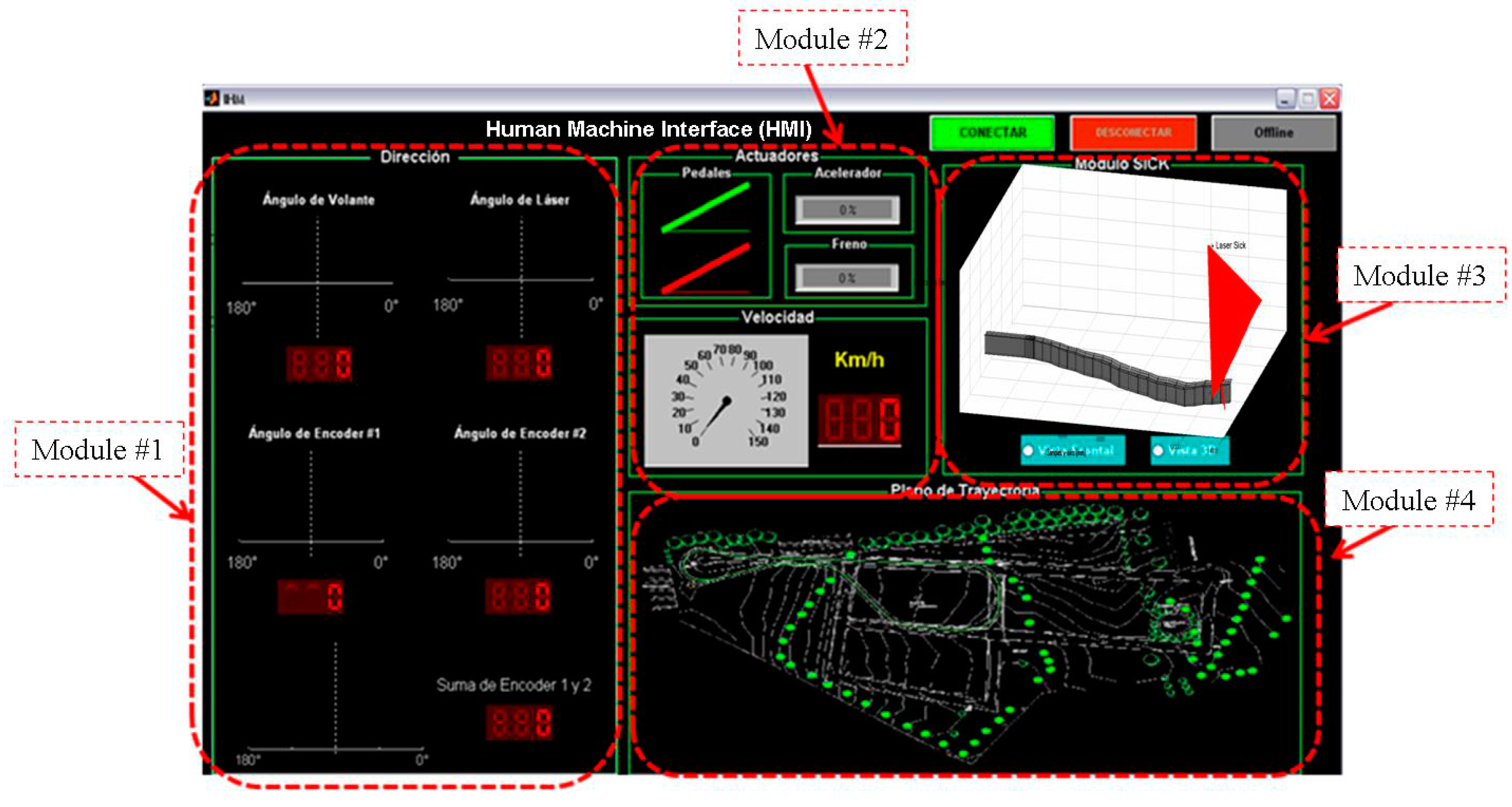
The i-client consists of a graphical interface and a “Configuration_Profile Manager”. The graphical environment is intended to display the multiple variables of the vehicle; the variables are classified and positioned in four groups or modules (see Figure 9). Module #1 displays the variables strongly associated with the steering control: the steering wheel position (angle) and the trajectory deviation angle. Module #2 shows the variables related to vehicle movement, i.e., the velocity and the interpretation of the brake and accelerator pedals. Module #3 is used for the depiction of the information acquired by the range sensor (LIDAR), whether it is displaying the data in 2D or 3D. Module #4 shows the bus trajectory. The Configuration_Profile Manager is in charge of supervising the execution of the i-client, according to the user’s requirements.
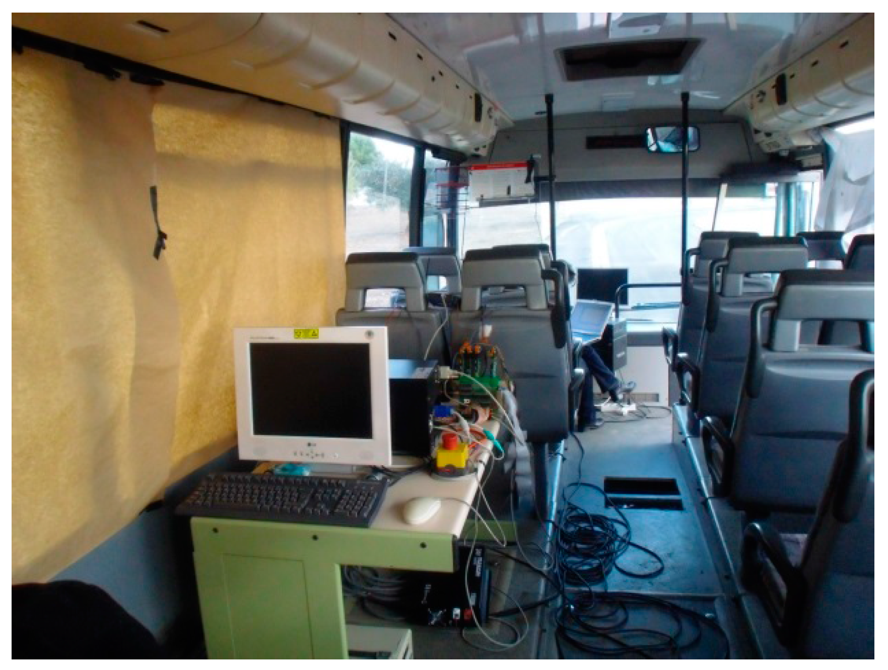
The remote communication begins by means of any i-client. The first action is the i-client identification; then, it sends its initial configuration profile, previously established, where the user chooses the variables of the system to be monitored. Once the configuration has been confirmed, the server starts the data sending procedure. This process will be performed until one of the linked parts breaks the connection. Due to the communication system being designed to operate with multiple and simultaneous clients/users, the server performance is not affected when an i-client is disconnected or a new i-client is connected. The Clients Manager creates an independent channel for every i-client, and when the server is disconnected, it sends a shutting down signal to all connected clients. The communication experiments were carried out at the CSIC premises where the network and the data traffic were monitored by the IT services. An optimal wireless connection for the on-board and the client PCs was created with the combination of an access point and range extender devices. In that way, the maximum bandwidth of the network was available. Although a detailed scaling analysis was not performed, because it was not needed for the experiments, there was a testing of the communication channels and the multiple-thread safety situation, and the maximum number of clients connected at the same time was ten. With ten connected clients, no significant problem regarding the server and the channel resources was detected. Figure 10 shows the HMI on board the bus during a test on the CSIC inner road.
2.6. System Architecture
In order to achieve great flexibility in the experimental platform, the reference trajectory for the lateral control might be provided by different systems that could be employed as a single source of reference points or to investigate a suitable combination of sensors and sensor fusion algorithms: GPS, computer vision (B&W, RGB, stereo, omnidirectional), LIDAR, TOF, magnetometers detecting hidden magnets and odometers whose data are provided by encoders. Some of these sensors could be used also for longitudinal control (i.e., to detect obstacles like pedestrians with computer vision or LIDAR, to locate and identify traffic signals, to determine distance and velocity approach to other vehicles, etc.).
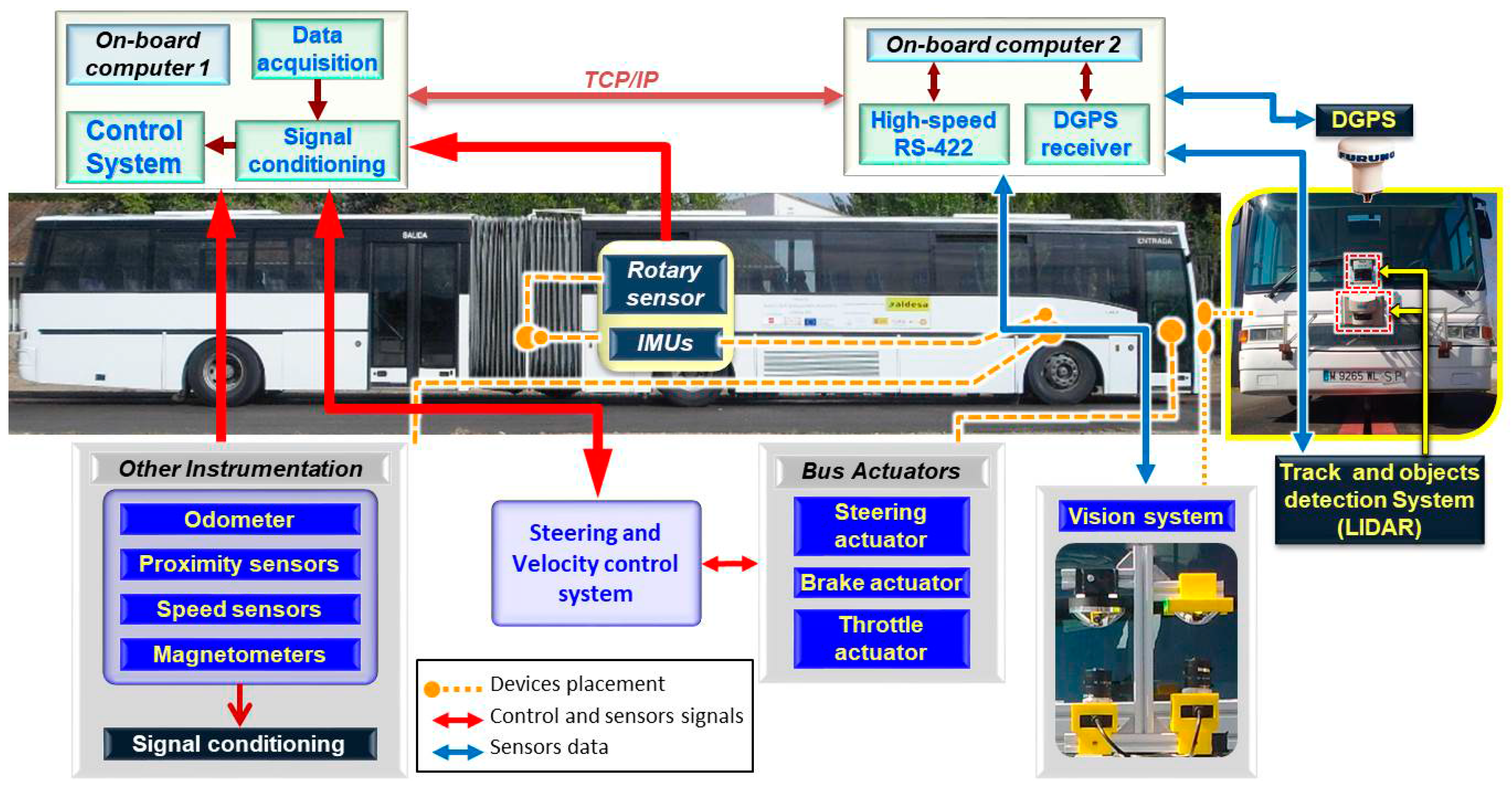
The source data for the bus’s desired trajectory are processed by the control system, and specific filtering is applied depending on the selected source. The overall system architecture is illustrated in Figure 11, and a general view of the installed instrumentation inside the bus is shown in Figure 12.
3. Results and Discussion
The automatic control of an articulated bus, presents, at a high level, some features similar to other automatic vehicles, mainly regarding instrumentation and communications [66,67,68,69]. However, from the point of view of practical implementation and low-level control, there are some challenging differences. One major difference is inertia, which means greater power is involved and, so, more demanding control and safety measures must be applied, those being of special relevance when coping with down slopes. As a consequence, braking strategies and accelerations (longitudinal, lateral) are now of greater relevance with respect to those of cars or small buses as is the case of the European project CityMobil2 [70]. A second key difference with automatic cars or small buses [66] is the very long length of an articulated bus (about 18 m), which, adding the position of the steering wheel ahead of the front wheels (the bus driver is seated ahead of the front wheels), makes turning maneuvers very cumbersome (in fact, during our experiments, one of the most “striking” sensations was when approaching a curve and the steering wheel did not turn for a while, then it started to turn when the front wheels where required to follow the curve). Furthermore, because of the bus length and the presence of its central articulation, the trajectories of the front, middle and rear wheels present more differences than in the case of a shorter vehicle [66], where practically the rear wheels are able to track the front wheels’ trajectory [27]. This intrinsic articulated bus characteristic requires special attention when calculating the required steering angles for the desired bus trajectory.
The longitudinal control of the articulated bus is carried out so that the vehicle will be able to move ahead of the test lane at a desired speed. The speed used in most experiments was relatively slow due to safety reasons and to the intricacy of the trajectory (please refer to Figure 1) intended more for checking control performance than to go very fast. The average speed in the experiments was ranging from 10 km/h to 25 km/h. However, in the straight section of the path, in some controlled experiments, the speed went up to 60 km/h.
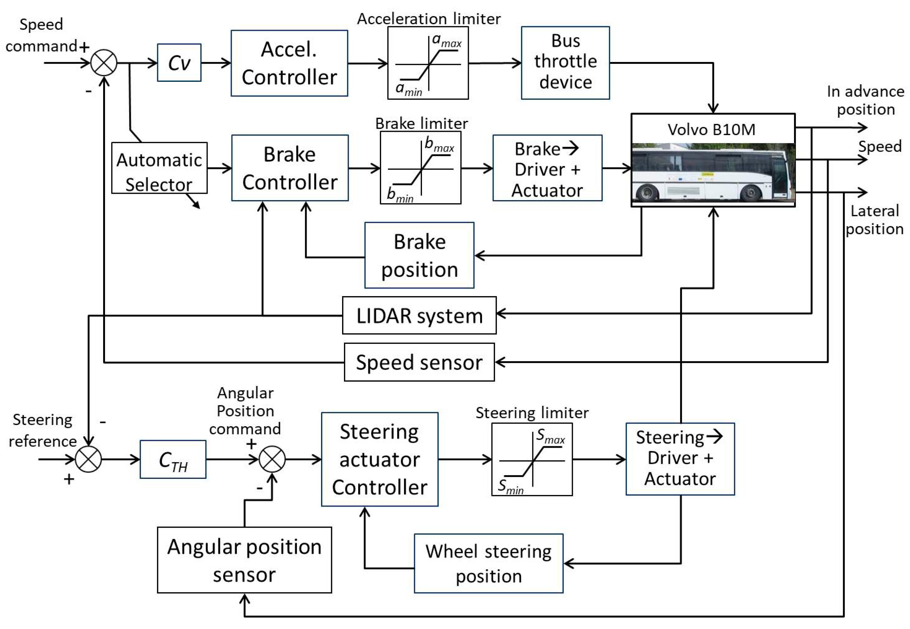
Figure 13 shows the longitudinal and lateral control scheme implemented in the bus Volvo B10M ART-RA-IN. Regarding longitudinal control, the system acts on the PotBox of the bus, which has an action range of 0 to 5 DC volts, rather than acting on the throttle, because the control over acceleration/speed of the bus is better in this case and more controllable. The acceleration is limited (saturated) in order to protect the PotBox and not to exceed the desired speed over limits that cannot be controlled, according to the experimental tests.
When the bus exceeds the desired speed, then the acceleration controller stops and selects the brake controller. The brake controller has minimum and maximum limits, which determine the workspace for this controller. Within these limits, the brake controller generates a saw-tooth signal to act on the brake actuator, which consists of a DC servomotor (see Figure 3). This makes the brake subsystem perform stopping of the bus as a gentle deceleration. When the speed decreases to a pre-set threshold, the brake subsystem stops acting and starts the accelerator subsystem. The bus speed is measured by a speed sensor whose resolution is greater than that offered by the original bus tachometer.
Regarding lateral control, an electric actuator composed of a DC motor, gearbox and encoder has been installed on the steering column (see Figure 5). The actuator receives commands from the lateral control system, so that the vehicle will track the desired trajectory. It takes into account the steering limit, which in this case is ±900°. At the same time, it makes the axle of the front wheel range between ±45°. The feedback to the lateral control system is obtained by means of actual (lateral) position information in the form of the angular position (obtained from the different sensing possibilities: GPS, magnetometers, encoders, etc.), which is compared with the angular position command.
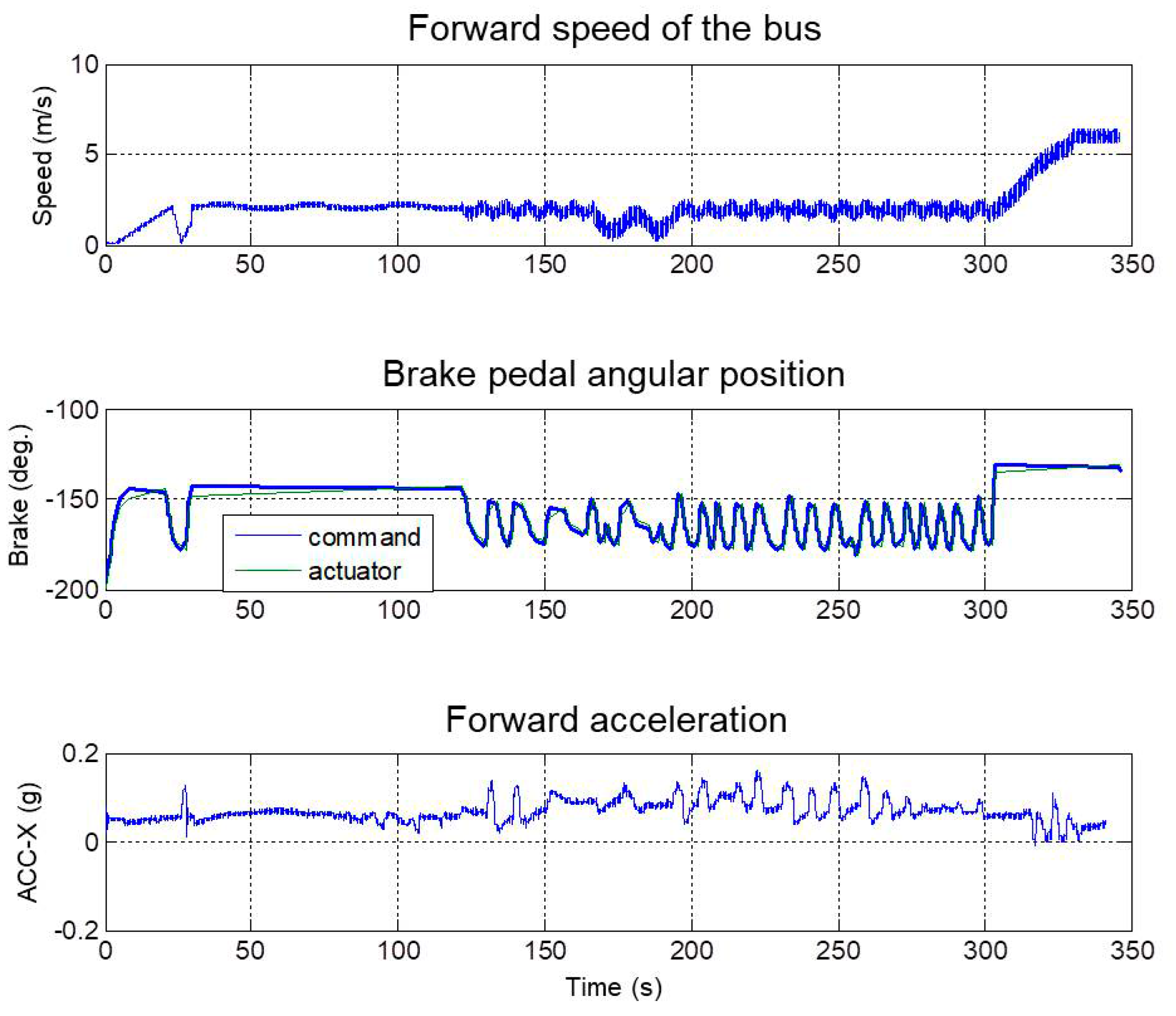
The results of longitudinal control for one of the experiments can be noticed in Figure 14, where a comparison among the speed of the vehicle, the position of the brake and the acceleration along the longitudinal axis (bus forward motion) obtained through an IMU installed on the front axle is presented. In this experiment and during most of the trajectory, the commanded speed was about 10 km/h, because the test lane contains small radii of curvature and slopes. In the last trajectory segment of the test lane (straight line), the speed was increased up to 20 km/h. It can be noticed in Figure 14 that 25 s after the start, the brake system applies a brake signal to check if the system is working properly. Then, the main application of the brake controller is to regulate the speed commanded mainly during the downward slope section. This takes place between the times 125 and 300 s, approximately. It can be noticed in Figure 14, for this period of time, that the brake signal (and correspondingly, the acceleration signal) shows an oscillation due to the chosen algorithm for the brake system, where a command signal in the shape of a saw-tooth is entered into the brake controller, which acts as a Proportional-Integral (PI) action and provides a comfortable sensation of very near constant speed, as should be expected.
Figure 15 shows the experimental results obtained by applying the lateral control of the bus for tracking the required trajectory. This figure shows the steering command, the lateral acceleration of the bus and the angular rate on the z-axis (azimuth). The angular rate sensor follows the curves of the trajectory commanded by the bus steering. The azimuthal speeds have been measured at two different points; the first, on the bus front axle, and the second, on the rotatory junction of the bus, in order to know both characteristics of its behavior. One of them is to know the position of the last section with respect to the first section of the bus. The lateral acceleration signal can be used in a feedback loop lateral control to improve the tracking of the trajectory. Using this signal in the control system, small lateral movements will be diminished.
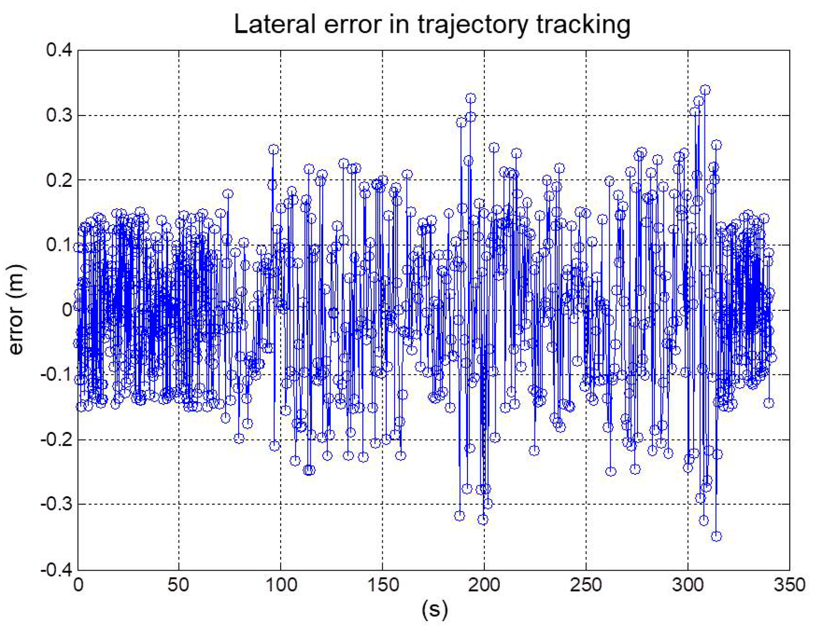
The lateral error during the trajectory tracking was relatively small and within the safety margins established in the control strategy. Figure 16 shows that the maximum peaks of the lateral error were approximately 0.35 m, these peaks being located in the smallest curvature radii sections, where the bus front is more separated from the theoretical trajectory to precisely cope with the curvature. During most of the trajectory, the lateral error was about or less than 0.10 m, which is acceptable for a bus of these dimensions.
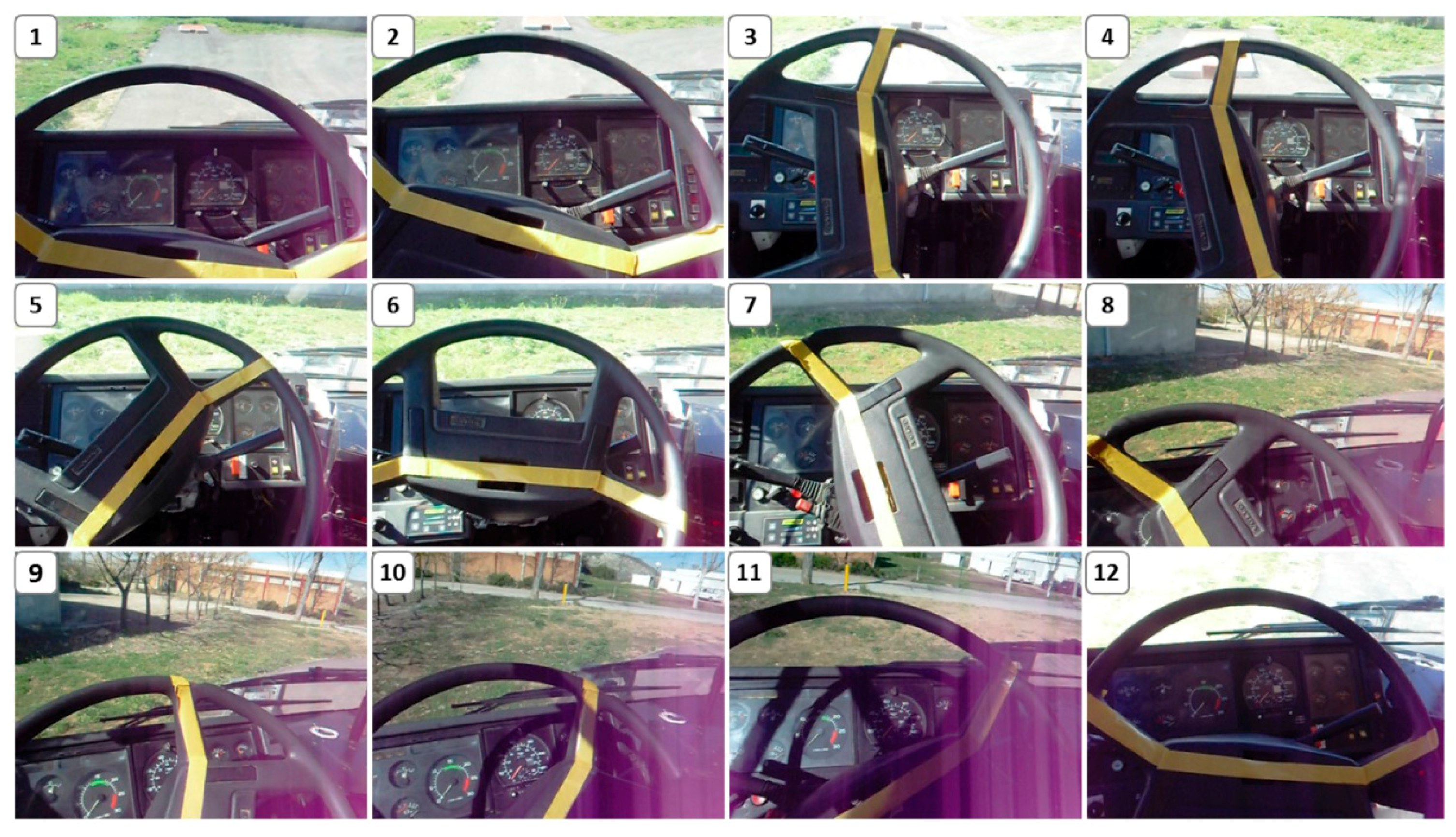
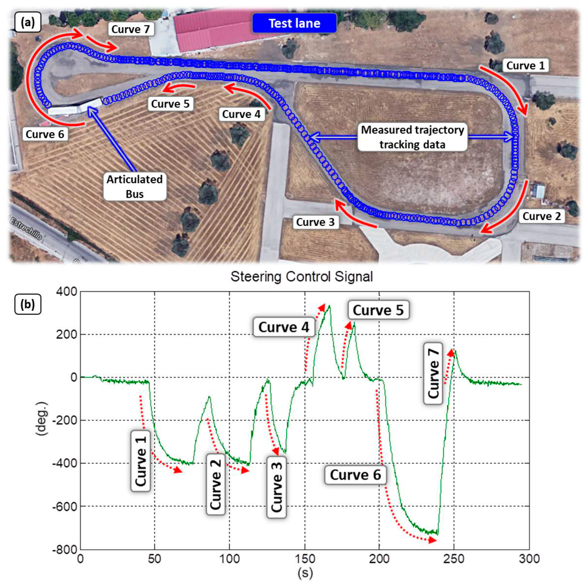
Many experiments have been performed within the CSIC experimental test area. Figure 17 illustrates the automatic control of the articulated bus following a required trajectory. The steering wheel angular rotation experimental data are shown as the correlation with the real trajectory. In this way, many longitudinal and lateral control algorithms were compared using this experimental platform, where reliable external references, sensors and electronic instrumentation have been demonstrated to be very useful. Figure 18 shows the steering wheel in automatic mode in several positions (video snapshots) when the bus is passing by one curved section of the test lane, during one of the experimental proofs.
4. Conclusions
In this paper, an experimental platform for research on the automatic control of an articulated bus aiming to allow full experimentation in real conditions for testing technological developments and control algorithms in the field of Intelligent Transportation Systems (ITS) has been introduced. A short review of the state of the art in ITS served as a motivation for the undertaken work, and it was followed by the presentation of the experimental platform, which consisted of a mobile component (a commercial articulated bus fully instrumented) and of a ground test area composed of asphalt roads inside the CSIC premises in Madrid. A robust information acquisition architecture composed of a heterogeneous and complementary set of sensors was implemented and integrated on the platform in order to provide real-time monitoring and control of the multiple variables involved in the autonomous operation of the articulated bus. Details regarding instrumentation and the implementation of bus velocity and steering control, as well as obstacle detection and a human machine interface developed to ease progress in the control system evaluation were provided.
Experimental testing of longitudinal and lateral control approaches were also presented and illustrated with the results of many tests performed within the experimental area. Experimental results exhibit that the proposed velocity control, which is based on a PID closed-loop controller, is capable of providing automatic regulation of the velocity independently of the road slope and the demanding layout of the bus track. On the other hand, the steering control was shown to keep the lateral error below 0.10 m during the trajectory tracking experiments, which is quite acceptable for a bus of these dimensions. The safety system was confirmed to be effective in detecting dynamic obstacles and sorting them into three predefined warning sections. This strategy allows the articulated bus either to stop or to reduce its velocity depending on the distance between the obstacle and the vehicle. Finally, the HMI proved to be a friendly and intuitive means of communication between the human operator and the controlled articulated bus. The adaptable and open configuration of the HMI enables the real-time control of the system, as well as the real-time visualization of the multiple variables of interest acquired by the sensors.
In future works, we will implement and evaluate different controllers for this experimental platform in order to compare them in order to reach new conclusions.
Acknowledgments
The authors acknowledge partial funding of this research under: IMADE (Instituto Madrileño de Desarrollo) PIE/62/2008 (Comunidad de Madrid), RoboCity2030 (Phase III) S-2013/MIT-2748, Comunidad de Madrid, and ROBSEN (Robotica y Sensores para los Retos Sociales) PI-201650E050, CSIC. Héctor Montes acknowledges support from Universidad Tecnológica de Panamá. Roemi Fernández acknowledges the financial support from the Ministry of Economy, Industry and Competitiveness under the Ramón y Cajal Programme.
Author Contributions
The work presented in this article was carried out in cooperation with all authors. Hector Montes designed and wrote the manuscript in collaboration with Manuel Armada. Hector Montes, Carlota Salinas, Roemi Fernández and Manuel Armada conceived of and designed the experiments. Héctor Montes and Carlota Salinas performed the experiments for autonomous control of the bus and for data acquisition. Carlota Salinas, Roemi Fernández and Héctor Montes processed and analyzed the data and drew the main conclusions. Héctor Montes implemented the architecture of the experimental platform. Carlota Salinas implemented the HMI. All authors contributed to the review of the manuscript.
Conflicts of Interest
The authors declare no conflict of interest.
References
- Shladover, S.E.; Desoer, C.A.; Hedrick, J.K.; Tomizuka, M.; Walrand, J.; Zhang, W.-B.; McMahon, D.H.; Peng, H.; Sheikholeslam, S.; McKeown, N. Automatic vehicle control developments in the path program. IEEE Trans. Veh. Technol. 1991, 40, 114–130. [Google Scholar] [CrossRef]
- Fenton, R.; Mayhan, R. Automated highway studies at the Ohio State University-an overview. IEEE Trans. Veh. Technol. 1991, 40, 100–113. [Google Scholar] [CrossRef]
- Collier, W.C.; Weiland, R.J. Smart cars-smart highways. IEEE Spectr. 1994, 31, 27–33. [Google Scholar] [CrossRef]
- Stanton, N.A.; Young, M.; McCaulder, B. Drive-by-Wire: The case of driver workload and reclaiming control with adaptive cruise control. Saf. Sci. 1997, 27, 149–159. [Google Scholar] [CrossRef]
- Naranjo, J.E.; González, C.; García, R.; de Pedro, T. Cooperative Throttle and Brake Fuzzy Control for ACC+Stop&Go Maneuvers. IEEE Trans. Veh. Technol. 2007, 56, 1623–1630. [Google Scholar] [CrossRef]
- Naranjo, J.E.; González, C.; García, R.; de Pedro, T. Lane-Change Fuzzy Control in Autonomous Vehicles for the Overtaking Maneuver. IEEE Trans. Intell. Transp. Syst. 2008, 9, 438–450. [Google Scholar] [CrossRef] [Green Version]
- Bishop, R. A survey of intelligent vehicle applications worldwide. In Proceedings of the IEEE Intelligent Vehicles Symposium, Dearborn, MI, USA, 3–5 October 2000; pp. 25–30. [Google Scholar]
- Yoshioka, L.R.; Marte, C.L.; Micoski, M.; Costa, R.D.; Fontana, C.; Sakurai, C.A.; Cardoso, J.R. Bus Corridor Operational Improvement with Intelligent Transportation System based on Autonomous Guidance and Precision Docking. Int. J. Syst. Appl. Eng. Dev. 2014, 8, 116–123. [Google Scholar]
- Hidalgo, D.; Muñoz, J.C. A review of technological improvements in bus rapid transit (BRT) and buses with high level of service (BHLS). Public Transp. 2014, 6, 185–213. [Google Scholar] [CrossRef]
- Mejía-Dugand, S.; Hjelm, O.; Baas, L.; Ríos, R.A. Lessons from the spread of bus rapid transit in Latin America. J. Clean. Prod. 2013, 50, 82–90. [Google Scholar] [CrossRef]
- Zeng, H. China Transportation Briefing: Bus Rapid Transit in China—On the Way. TheCityFix. Available online: http://thecityfix.com/blog/bus-rapid-transit-brt-china-transportation-briefing-series-guangzhou-beijing-heshuang-zeng/ (accessed on 26 October2017).
- Cervero, R.; Dai, D. BRT TOD: Leveraging transit oriented development with bus rapid transit investments. Transp. Policy 2014, 36, 127–138. [Google Scholar] [CrossRef]
- Wright, L.; Hook, W. Introduction. In Bus Rapid Transit Planning Guide, 3rd ed.; Institute of Transportation & Development: New York, NY, USA, 2007; pp. 10–33. [Google Scholar]
- Montes, H.; Salinas, C.; Sarria, J.; Armada, M. An Experimental Platform for Research on Automatic Control of Articulated Bus. In Proceedings of the IARP Workshop on Service Robotics and Nanorobotics, Beijing, China, 28–29 October 2009. [Google Scholar]
- Salinas, C.; Montes, H.; Armada, M. A perception system for accurate automatic control of an articulated bus. In Proceedings of the 13th International Conference of Climbing and Walking Robots, CLAWAR 2010, Nagoya, Japan, 31 August–3 September 2010; pp. 1021–1028. [Google Scholar]
- Le-Anh, T.; De Koster, M.B.M. A review of design and control of automated guided vehicle systems. Eur. J. Oper. Res. 2006, 171, 1–23. [Google Scholar] [CrossRef]
- Ackermann, J.; Guldner, J.; Siegel, W.; Steinhauser, R.; Utkin, V.I. Linear and Nonlinear Controller Design for Robust Automatic Steering. IEEE Trans. Control Syst. Technol. 1995, 3, 132–143. [Google Scholar] [CrossRef]
- Campion, G.; Bastin, G.; D’Andrea-Novel, B. Structural Properties and Classification of Kinematic and Dynamic Models of Wheeled Mobile Robots. IEEE Trans. Robot. Autom. 1996, 12, 47–62. [Google Scholar] [CrossRef]
- Kodagoda, K.R.S.; Wijesoma, W.S.; Teoh, E.K. Fuzzy Speed and Steering Control of an AGV. IEEE Trans. Control Syst. Technol. 2002, 10, 112–120. [Google Scholar] [CrossRef]
- Falcone, P.; Borrelli, F.; Asgari, J.; Tseng, H.E.; Hrovat, D. Predictive Active Steering Control for Autonomous Vehicle Systems. IEEE Trans. Control Syst. Technol. 2007, 15, 566–580. [Google Scholar] [CrossRef]
- Fernández, C.; Domínguez, R.; Fernández-Llorca, D.; Alonso, J.; Sotelo, M.A. Autonomous navigation and obstacle avoidance of a micro-bus. Int. J. Adv. Robot. Syst. 2013, 10, 1–9. [Google Scholar] [CrossRef]
- Fenton, R.; Melocik, G.; Olson, K. On the steering of automated vehicles: Theory and experiment. IEEE Trans. Autom. Control 1976, 21, 306–315. [Google Scholar] [CrossRef]
- Netto, M.S.; Chaib, S.; Mammar, S. Lateral adaptive control for vehicle lane keeping. In Proceedings of the American Control Conference, Boston, MA, USA, 30 June–2 July 2004; pp. 2693–2698. [Google Scholar]
- Mammar, S.; Glaser, S.; Netto, M. Vehicle Lateral Dynamics Estimation using Unknown Input Proportional-Integral Observers. In Proceedings of the American Control Conference, Minneapolis, MN, USA, 14–16 June 2006; pp. 14–16. [Google Scholar]
- Chen, C.; Guldner, J.; Kanellakopoulos, I.; Tomizuka, M. Nonlinear Damping in Vehicle Lateral Control: Theory and Experiment. In Proceedings of the American Control Conference, Philadelphia, PA, USA, 26 June 1998; pp. 2243–2247. [Google Scholar]
- Linderoth, M.; Soltesz, K.; Murray, R.M. Nonlinear Lateral Control Strategy for Nonholonomic Vehicles. In Proceedings of the American Control Conference, Seattle, WA, USA, 11–13 June 2008; pp. 3219–3224. [Google Scholar]
- DARPA Urban Challenge. Available online: http://archive.darpa.mil/grandchallenge/ (accessed on 6 September 2017).
- Kammel, S.; Ziegler, J.; Pitzer, B.; Werling, M.; Gindele, T.; Jagzent, D.; Schröder, J.; Thuy, M.; Goebl, M.; von Hundelshausen, F.; et al. Team AnnieWAY’s Autonomous System for the 2007 DARPA Urban Challenge. J. Field Robot. 2008, 25, 615–639. [Google Scholar] [CrossRef]
- Sotelo, M.A. Lateral control strategy for autonomous steering of Ackerman-like vehicles. Robot. Auton. Syst. 2003, 45, 223–233. [Google Scholar] [CrossRef]
- Hessburg, T.; Peng, H.; Tomizuka, M.; Zhang, W.B.; Kamei, E. An Experimental Study on Lateral Control of a Vehicle. In Proceedings of the American Control Conference, Boston, MA, USA, 26–28 June 1991; pp. 3084–3089. [Google Scholar]
- Tan, H.S.; Bougler, B. Vehicle Lateral Warning, Guidance and Control Based on Magnetic Markers: PATH Report of AHSRA Smart Cruise 21 Proving Tests. In California Partners for Advanced Transit and Highways (PATH); UC Berkeley: California Partners for Advanced Transportation Technology; UC Berkeley: Berkeley, CA, USA, 2001; pp. 1–71. Available online: http://escholarship.org/uc/item/3jb3r4p5 (accessed on 7 September 2017).
- Xu, H.G.; Wang, C.X.; Yang, R.Q.; Yang, M. Extended Kalman Filter Based Magnetic Guidance for Intelligent Vehicles. In Proceedings of the IEEE Intelligent Vehicles Symposium, Tokyo, Japan, 13–15 June 2006; pp. 169–175. [Google Scholar]
- Chen, C.; Tomizuka, M. Lateral Control of Tractor-Semitrailers for Automated Highway Systems. In California Partners for Advanced Transit and Highways (PATH); UC Berkeley: California Partners for Advanced Transportation Technology; UC Berkeley: Berkeley, CA, USA, 1996; pp. 1–29. Available online: http://escholarship.org/uc/item/5235j21k (accessed on 7 September 2017).
- Hingwe, P.; Wang, J.Y.; Tai, M.; Tomizuka, M. Lateral Control of Heavy Duty Vehicles for Automated Highway System: Experimental Study on a Tractor Semi-trailer. In California Partners for Advanced Transit and Highways (PATH); UC Berkeley: California Partners for Advanced Transportation Technology; UC Berkeley: Berkeley, CA, USA, 2000; pp. 1–47. Available online: http://escholarship.org/uc/item/9jj235kx (accessed on 7 September 2017).
- Tai, M.; Tomizuka, M. Robust Lateral Control of Heavy Duty Vehicles: Final Report. In California Partners for Advanced Transit and Highways (PATH); UC Berkeley: California Partners for Advanced Transportation Technology; UC Berkeley: Berkeley, CA, USA, 2003; pp. 1–80. Available online: http://escholarship.org/uc/item/8j2692w0 (accessed on 7 September 2017).
- Chen, C. Backstepping Design of Nonlinear Systems and Its Application to Vehicle Lateral Control in Automated Highway Systems. Ph.D. Thesis, University of California Berkeley, Berkeley, CA, USA, 1996. [Google Scholar]
- Fernández, R.; Aracil, R.; Armada, M. Control de tracción en robots móviles con ruedas. Rev. Iberoam. Autom. Inf. Ind. 2012, 9, 393–405. [Google Scholar] [CrossRef] [Green Version]
- Kiencke, U.; Daiß, A. Observation of lateral vehicle dynamics. Control Eng. Pract. 1997, 5, 1145–1150. [Google Scholar] [CrossRef]
- Lin, C-F.; Ulsoy, A.G.; LeBlanc, D.J. Vehicle Dynamics and External Disturbance Estimation for Vehicle Path Prediction. IEEE Trans. Control Syst. Technol. 2000, 8, 508–518. [Google Scholar] [CrossRef]
- Gerdes, J.C.; Rossetter, E.J. A unified approach to driver assistance systems based on artificial potential fields. In Proceedings of the ASME International Mechanical Engineering Congress and Exposition, Nashville, TN, USA, 14–19 November 1999; pp. 431–438. [Google Scholar]
- Talbot, C.M.; Papadimitriou, I.; Tomizuka, M. Fault Tolerant Autonomous Lateral Control for Heavy Vehicles. In California Partners for Advanced Transit and Highways (PATH); UC Berkeley: California Partners for Advanced Transportation Technology; UC Berkeley: Berkeley, CA, USA, 2004; pp. 1–69. Available online: http://escholarship.org/uc/item/7xd2r0cc (accessed on 7 September 2017).
- Mcmahon, D.H.; Hedrick, J.K. Longitudinal Model Development for Automated Roadway Vehicles. In California Partners for Advanced Transit and Highways (PATH); UC Berkeley: California Partners for Advanced Transportation Technology; UC Berkeley: Berkeley, CA, USA, 1989; pp. 1–69. Available online: http://escholarship.org/uc/item/4746j7jj (accessed on 7 September 2017).
- Tan, Y.; Kanellakopoulos, I. Longitudinal Control of Commercial Heavy Vehicles: Experimental Implementation. In California Partners for Advanced Transit and Highways (PATH); UC Berkeley: California Partners for Advanced Transportation Technology; UC Berkeley: Berkeley, CA, USA, 2002; pp. 1–27. Available online: https://trid.trb.org/view.aspx?id=726231 (accessed on 7 September 2017).
- Kim, S.; Song, B.; Song, H. Integrated Fault Detection and Diagnosis System for Longitudinal Control of an Autonomous All-Terrain Vehicle (ATV). Int. J. Autom. Technol. 2009, 10, 505–512. [Google Scholar] [CrossRef]
- Lim, E.H.M.; Hedrick, J.K. Lateral and Longitudinal Vehicle Control Coupling for Automated Vehicle Operation. In Proceedings of the American Control Conference, San Diego, CA, USA, 2–4 June 1999; pp. 3676–3680. [Google Scholar]
- Tan, H.S.; Huang, J. Design of a high-performance automatic steering controller for bus revenue service based on how drivers steer. IEEE Trans. Robot. 2014, 30, 1137–1147. [Google Scholar] [CrossRef]
- Huang, J.; Tan, H.S. Control System Design of an Automated Bus in Revenue Service. IEEE Trans. Intell. Transp. Syst. 2016, 17, 2868–2878. [Google Scholar] [CrossRef]
- Lefèvre, S.; Carvalho, A.; Borrelli, F. A learning-based framework for velocity control in autonomous driving. IEEE Trans. Autom. Sci. Eng. 2016, 13, 32–42. [Google Scholar] [CrossRef]
- Justino, J.C.; da Silva, L.A.; Rocha, A.; Cardoso Filho, B.D.J. Aspects of the operation of regular ultra fast charging e-Bus in high grade BRT routes. In Proceedings of the IECON 40th Annual Conference of the IEEE Industrial Electronics Society, Dallas, TX, USA, 29 October–1 November 2014; pp. 3101–3107. [Google Scholar]
- Baber, J.; Kolodko, J.; Noël, T.; Parent, M.; Vlacic, L. Cooperative Autonomous Driving. Intelligent Vehicles Sharing City Roads. IEEE Robot. Autom. Mag. 2005, 12, 44–49. [Google Scholar] [CrossRef]
- Jiménez, F.; Clavijo, M.; Naranjo, J.E.; Gómez, O. Improving the Lane Reference Detection for Autonomous Road Vehicle Control. J. Sens. 2016, 2016. [Google Scholar] [CrossRef]
- González, D.; Pérez, J.; Milanés, V. Parametric-based path generation for automated vehicles at roundabouts. Exp. Syst. Appl. 2017, 71, 332–341. [Google Scholar] [CrossRef]
- Szadeczky-Kardoss, E.; Kiss, B. Path planning and tracking control for an automatic parking assist system. In European Robotics Symposium 2008; Springer Tracts in Advanced Robotics; Bruyninckx, H., Přeučil, L., Kulich, M., Eds.; Springer: Berlin, Germany, 2008; Volume 44, pp. 175–184. ISBN 978-3-540-78315-2. [Google Scholar]
- Naranjo, J.E.; González, C.; Reviejo, J.; Garcia, R.; de Pedro, T. Adaptive fuzzy control for inter-vehicle gap keeping. IEEE Trans. Intell. Transp. Syst. 2003, 4, 132–142. [Google Scholar] [CrossRef] [Green Version]
- Naranjo, J.E.; González, C.; García, R.; de Pedro, T. ACC + Stop&go maneuvers with throttle and brake fuzzy control. IEEE Trans. Intell. Transp. Syst. 2006, 7, 213–225. [Google Scholar] [CrossRef]
- Naranjo, J.E.; Sotelo, M.A.; González, C.; García, R.; de Pedro, T. Using Fuzzy Logic in Automated Vehicle Control. IEEE Intell. Syst. 2007, 22, 36–45. [Google Scholar] [CrossRef]
- Villalon-Sepulveda, G.; Torres-Torriti, M.; Flores-Calero, M. Traffic sign detection system for locating road intersections and braking advance. Rev. Iberoam. Autom. Inf. Ind. 2017, 14, 152–162. [Google Scholar] [CrossRef]
- Fernandez, A.; Usamentiaga, R.; Casado, R. Automatic System to Detect Both Distraction and Drowsiness in Drivers Using Robust Visual Features. Rev. Iberoam. Autom. Inf. Ind. 2017, 14, 307–328. [Google Scholar] [CrossRef]
- Salinas, C.; Montes, H.; Fernandez, G.; Gonzalez de Santos, P.; Armada, M. Catadioptric Panoramic Stereovision for Humanoid Robots. Robotica 2012, 30, 799–811. [Google Scholar] [CrossRef]
- Fernández, R.; Salinas, C.; Montes, H.; Armada, M. Omnidirectional stereo tracking system for humanitarian demining training. In Proceedings of the 8th International Symposium “Humanitarian Demining 2011”, Šibenik, Croacia, 26–28 April 2011; pp. 113–116. [Google Scholar]
- Salinas, C. A Non-Feature Based Method for Automatic Image Registration Relying on Depth Dependent Planar Projective Transformations. Ph.D. Thesis, Universidad Complutense de Madrid, Madrid, Spain, 2015. [Google Scholar]
- Li, Y.; Ruichek, Y.; Cappelle, C. 3D triangulation based extrinsic calibration between a stereo vision system and a LIDAR. In Proceedings of the 14th International IEEE Conference on Intelligent Transportation Systems (ITSC), Washington, DC, USA, 5–7 October 2011; pp. 797–802. [Google Scholar]
- Mozos, O.M. Semantic Place Labeling with Mobile Robots; Springer Tracts in Advanced Robotics (STAR); Springer: Berlin, Germany, 2010; ISBN 978-3-642-11209-6. [Google Scholar]
- QNX® Software System Ltd. QNX 6.4. 2008. Available online: http://www.qnx.com/download/ (accessed on 15 September 2017).
- The MathWorks. Matlab®. 2013. Available online: https://es.mathworks.com/ (accessed on 15 September 2017).
- FORTUNE. Available online: http://fortune.com/2016/12/13/google-self-driving-car-waymo-alphabet/ (accessed on 13 October 2017).
- TESLA. Available online: https://www.tesla.com/ (accessed on 13 October 2017).
- OLLI. Available online: http://meetolli.auto (accessed on 13 October 2017).
- OTTO. Available online: https://www.ottomotors.com/ (accessed on 13 October 2017).
- Alessandrini, A.; Cattivera, A.; Holguin, C.; Stam, D. CityMobil2: Challenges and Opportunities of Fully Automated Mobility. In Road Vehicle Automation; Meyer, G., Beiker, S., Eds.; Springer: Cham, Switzerland, 2014; pp. 169–184. ISBN 978-3-319-05989-1. [Google Scholar]
Figure 1.
Experimental platform main elements. (a) Articulated bus Volvo B10M-ART-RA-IN; (b) inner road facility dimensions; (c) Bus trajectory analysis in one section of the path.
Figure 1.
Experimental platform main elements. (a) Articulated bus Volvo B10M-ART-RA-IN; (b) inner road facility dimensions; (c) Bus trajectory analysis in one section of the path.
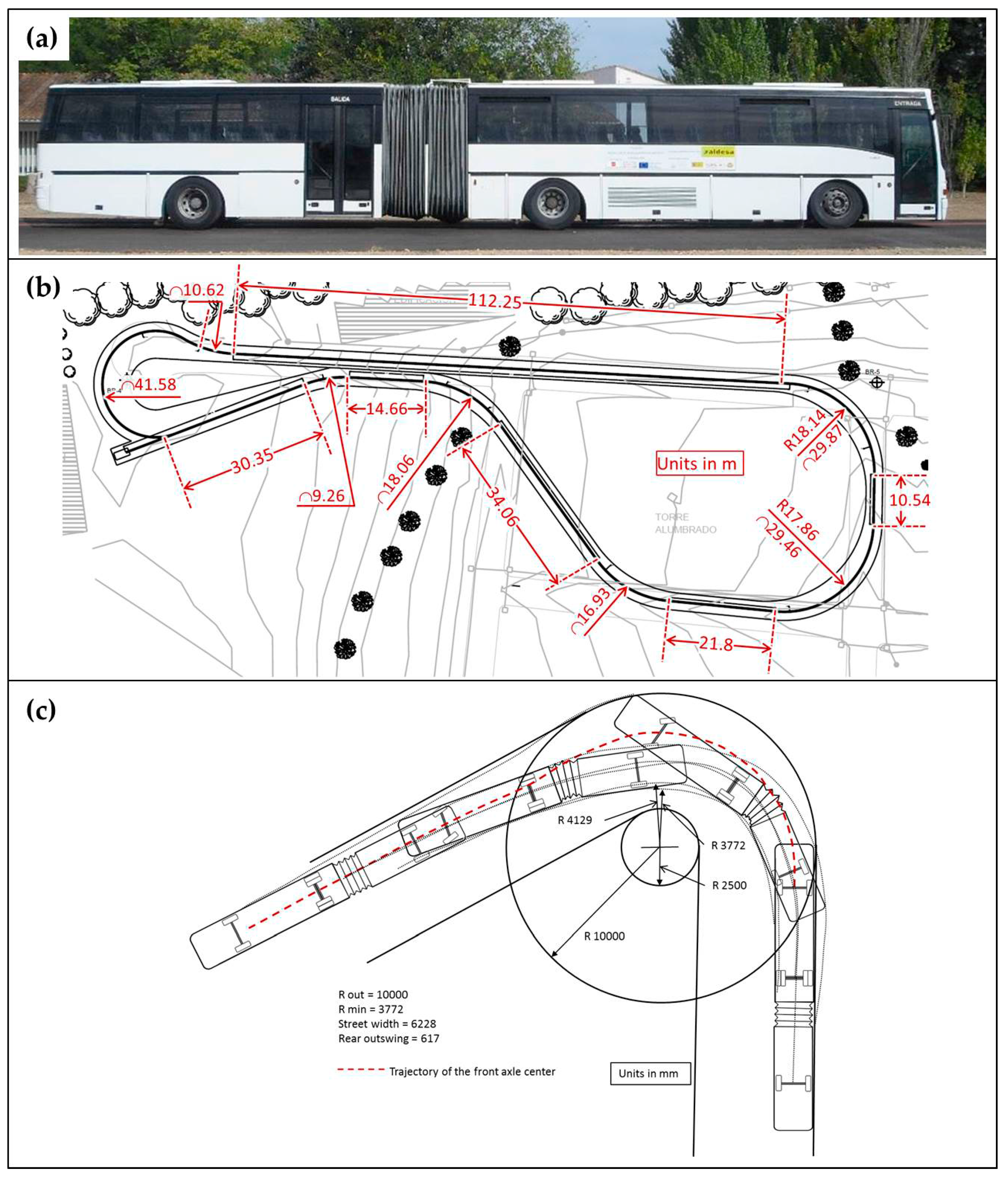
Figure 2.
Some sensors used in the proposed experimental platform. (a) Industrial-grade absolute optical encoders; (b) LIDAR sensors being tested in the lab; (c) MEMS inertial sensor testing.
Figure 2.
Some sensors used in the proposed experimental platform. (a) Industrial-grade absolute optical encoders; (b) LIDAR sensors being tested in the lab; (c) MEMS inertial sensor testing.
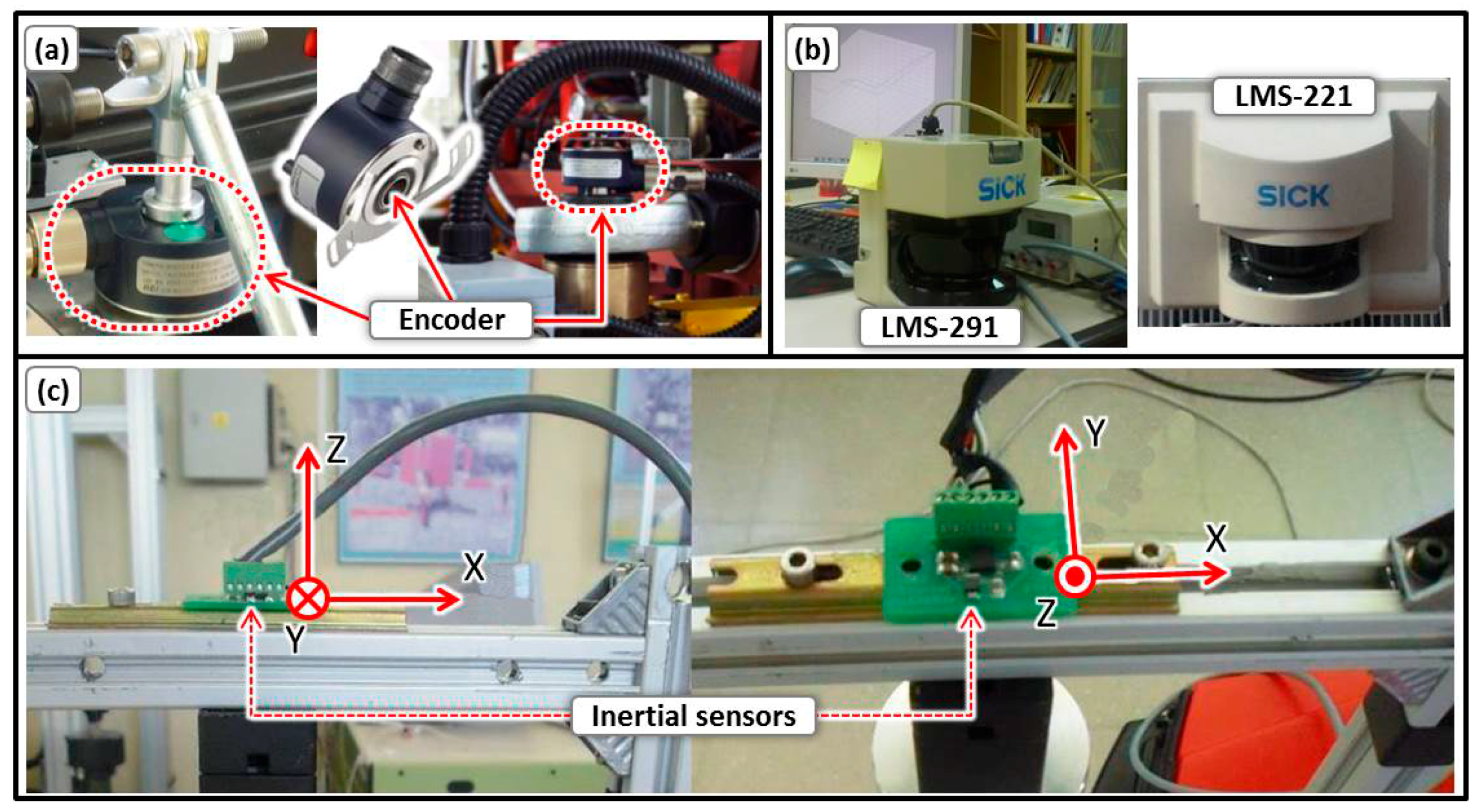
Figure 3.
Actuator implementation for the brakes.

Figure 4.
Implemented flowchart for velocity control.

Figure 5.
Actuator assembly for driving the steering wheel.
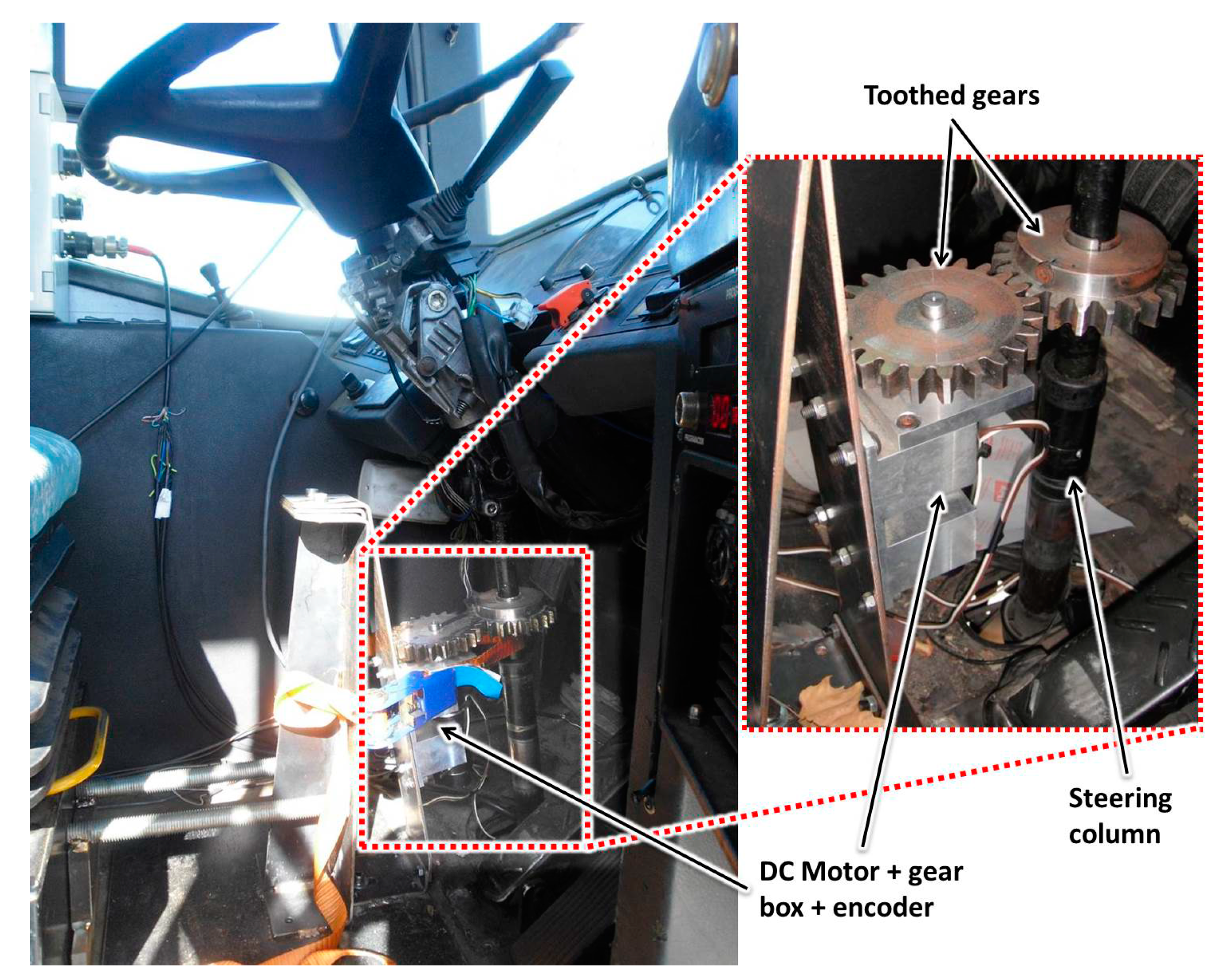
Figure 6.
Implemented flowchart for steering control.

Figure 7.
(a) LIDAR sensors placed at the bus front; (b) omnidirectional stereo tracking system; (c) dynamic obstacle detection (more critical close up (Section 1), intermediate (Section 2) and less critical (Section 3)).

Figure 8.
General diagram of the remote system communication.
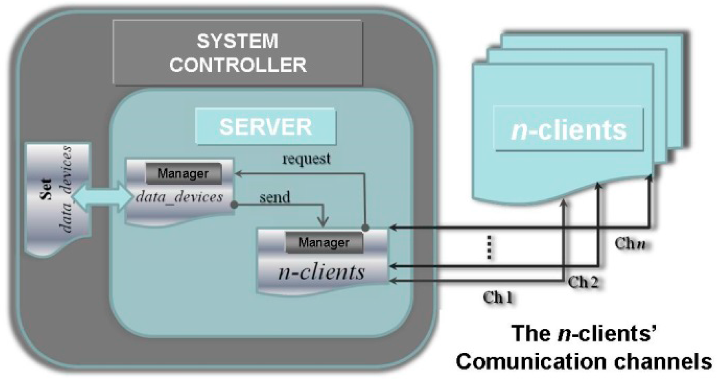
Figure 9.
HMI graphical environment.

Figure 10.
HMI graphical environment on board the bus during a test on the CSIC inner road.
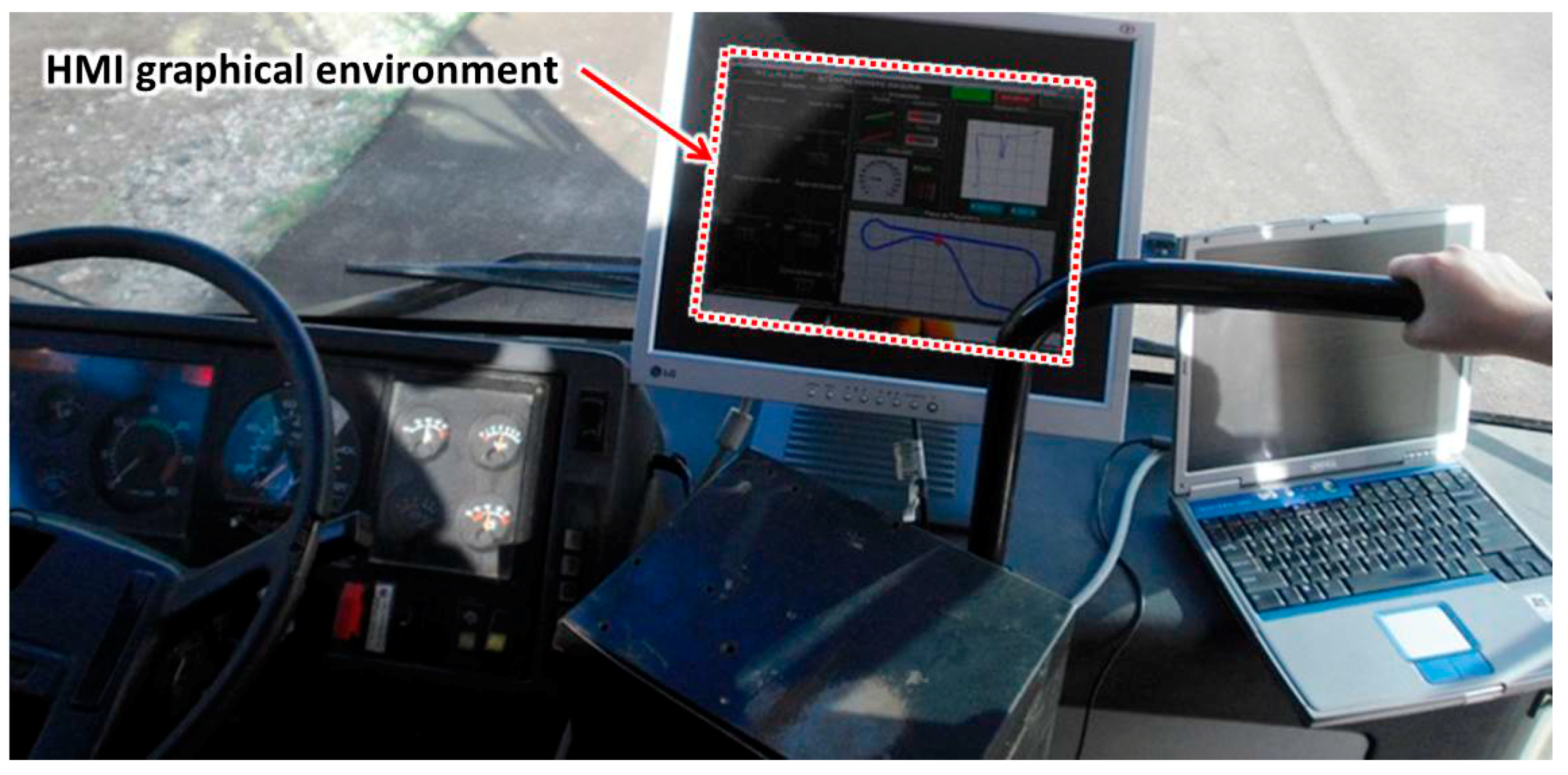
Figure 11.
The architecture of the experimental platform.

Figure 12.
On-board instrumentation and control system of the experimental platform.

Figure 13.
Longitudinal and lateral control scheme.

Figure 14.
Comparison among bus speed, brake position and x-acceleration during the tracking trajectory. Brake control is applied 25 s after the start and from the times 125 to 300 s to cope with a downslope in the circuit.
Figure 14.
Comparison among bus speed, brake position and x-acceleration during the tracking trajectory. Brake control is applied 25 s after the start and from the times 125 to 300 s to cope with a downslope in the circuit.

Figure 15.
Comparison among steering command, lateral acceleration and angular rate in the z-axis during the tracking of the trajectory.
Figure 15.
Comparison among steering command, lateral acceleration and angular rate in the z-axis during the tracking of the trajectory.
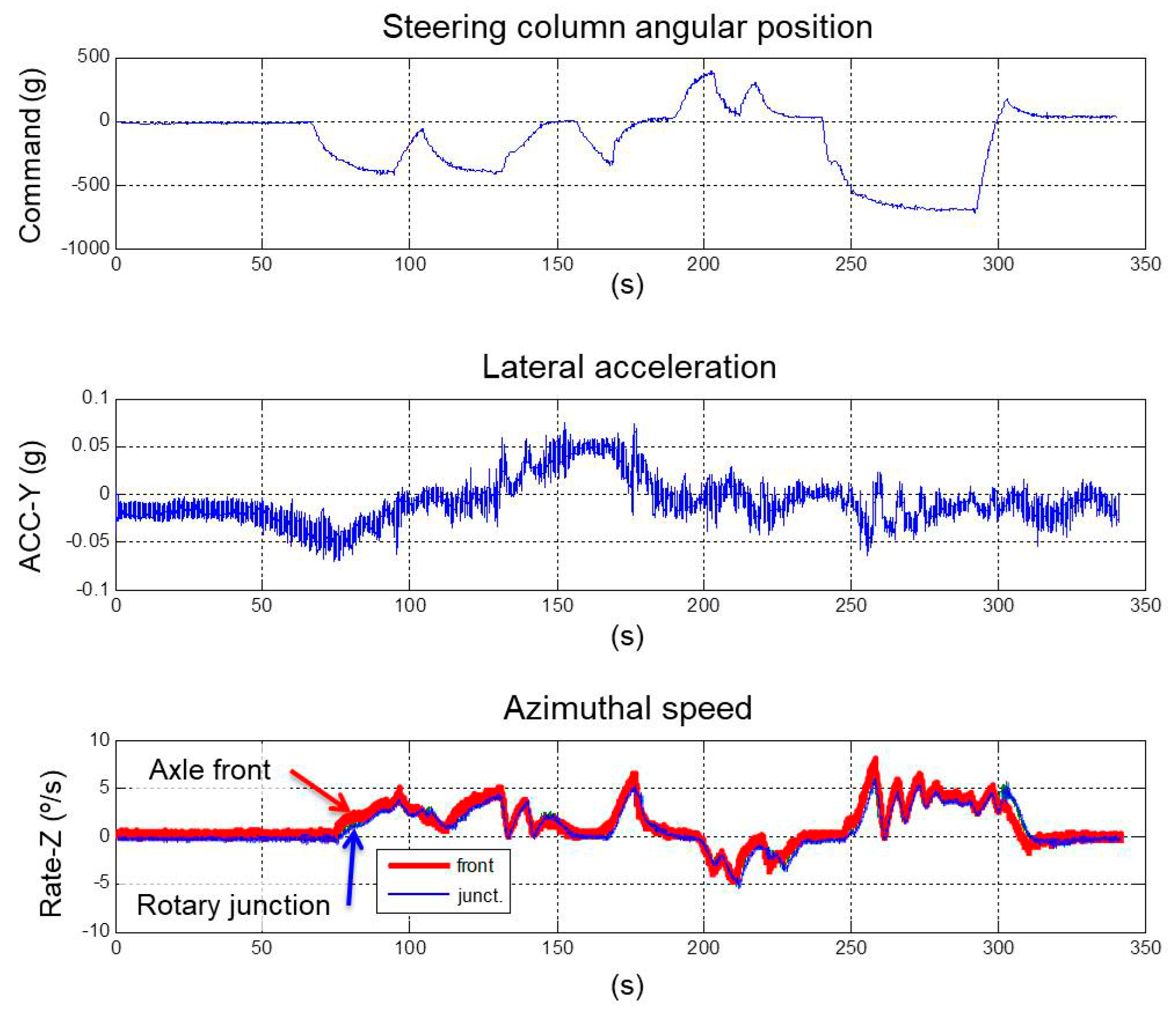
Figure 16.
Lateral error during the tracking of the test lane.

Figure 17.
(a) Test lane and trajectory at the CSIC; (b) steering wheel angular value during an experiment conducted on the test lane.
Figure 17.
(a) Test lane and trajectory at the CSIC; (b) steering wheel angular value during an experiment conducted on the test lane.

Figure 18.
Details of the steering wheel during one curved section of the experimental tests.

Table 1.
Sensors, actuators and computing and control equipment. CSIC, Consejo Superior de Investigaciones Científicas.
Table 1.
Sensors, actuators and computing and control equipment. CSIC, Consejo Superior de Investigaciones Científicas.
| Instrument | Function | Model |
|---|---|---|
| Sensors | Incremental and absolute optical encoders | HEDS 550X; Industrial encoder DH05 |
| Proximity sensors | NBB2-12GM50-E0-V1, E2EL cylindrical proximity sensor | |
| Velocity measurement system (magnetic pick-up) | KATLAX M18 Digital magnetic pick-up sensor | |
| Inertial Measurement Units (IMUs) (MEMS inertial sensor with three accelerometers) and high precision IMU | MEMS inertial sensor LIS3LO2AL IMU440CA | |
| Catadioptric omnidirectional stereovision system (with CCD RGB cameras) | Ueye UI-1485LE-C/M, resolution 2560 × 1920 pixels | |
| LIDAR systems (IP67, statistical error 5 mm, angular resolution 0.25°, range 80 m, view angle 180°) | SICK LMS221, LMS291 | |
| GPS for localization and tracking | TRIMBLE 5700 | |
| Magnetometer systems for magnetic markers detection | Honeywell HMC1501 | |
| Actuators | DC motor for steering wheel control | MAXON 24-volt DC motor (150 watts) with a gearbox (74:1) and encoder |
| DC motor for brake control | MAXON 24-volt DC motor (70 watts) with gearbox (74:1) and encoder | |
| Computing and control | Telemetry System | PCL-818, 16 I/O channels multifunction board Wireless-G Ethernet Bridge Wireless access point (WAP54G) |
| On-board computers | Industrial PCs running QNX RTOS | |
| DC motors microcontroller-based control boards | CM3 and CM4, proprietary CSIC control boards |
© 2017 by the authors. Licensee MDPI, Basel, Switzerland. This article is an open access article distributed under the terms and conditions of the Creative Commons Attribution (CC BY) license (http://creativecommons.org/licenses/by/4.0/).
Share and Cite
MDPI and ACS Style
Montes, H.; Salinas, C.; Fernández, R.; Armada, M. An Experimental Platform for Autonomous Bus Development. Appl. Sci. 2017, 7, 1131. https://doi.org/10.3390/app7111131
AMA Style
Montes H, Salinas C, Fernández R, Armada M. An Experimental Platform for Autonomous Bus Development. Applied Sciences. 2017; 7(11):1131. https://doi.org/10.3390/app7111131
Chicago/Turabian StyleMontes, Héctor, Carlota Salinas, Roemi Fernández, and Manuel Armada. 2017. "An Experimental Platform for Autonomous Bus Development" Applied Sciences 7, no. 11: 1131. https://doi.org/10.3390/app7111131
Note that from the first issue of 2016, this journal uses article numbers instead of page numbers. See further details here.