Effect of Molybdenum on the Microstructures and Properties of Stainless Steel Coatings by Laser Cladding
by
 ,
,
Kaiming Wang
1, 
Baohua Chang
1,*,
Jiongshen Chen
2,
Hanguang Fu
2,*,
Yinghua Lin
3 and
Yongping Lei
2 1
State Key Laboratory of Tribology, Department of Mechanical Engineering, Tsinghua University, Haidian District, Beijing 100084, China
2
School of Materials Science and Engineering, Beijing University of Technology, Number 100, Pingle Garden, Chaoyang District, Beijing 100124, China
3
Institute of Laser Advanced Manufacturing, Zhejiang University of Technology, Hangzhou 310014, Zhejiang, China
*
Authors to whom correspondence should be addressed.
Appl. Sci. 2017, 7(10), 1065; https://doi.org/10.3390/app7101065
Submission received: 11 September 2017
/
Revised: 11 September 2017
/
Accepted: 11 October 2017
/
Published: 15 October 2017
(This article belongs to the Special Issue Solid State Lasers Materials, Technologies and Applications)
Abstract
:Stainless steel powders with different molybdenum (Mo) contents were deposited on the substrate surface of 45 steel using a 6 kW fiber laser. The microstructure, phase, microhardness, wear properties, and corrosion resistance of coatings with different Mo contents were studied by scanning electron microscopy (SEM), electron probe microanalyzer (EPMA), X-ray diffraction (XRD), microhardness tester, wear tester, and electrochemical techniques. The results show that good metallurgical bonding was achieved between the stainless steel coating and the substrate. The amount of M7(C, B)3 type borocarbide decreases and that of M2B and M23(C, B)6 type borocarbides increases with the increase of Mo content in the coatings. The amount of martensite decreases, while the amount of ferrite gradually increases with the increase of Mo content. When the Mo content is 4.0 wt. %, Mo2C phase appears in the coating. The microstructure of the coating containing Mo is finer than that of the Mo-free coating. The microhardness decreases and the wear resistance of the coating gradually improves with the increase of Mo content. The wear resistance of the 6.0 wt. % Mo coating is about 3.7 times that of the Mo-free coating. With the increase of Mo content, the corrosion resistance of the coating firstly increases and then decreases. When the Mo content is 2.0 wt. %, the coating has the best corrosion resistance.
1. Introduction
Carbon steel and low alloy steel, which have a high strength, good processing performance, and low price, are widely used in marine environments [1,2]. Due to the complex environment of the ocean, some damage will inevitably occur on the surfaces of steels. The main failure ways of steel surfaces include wear, corrosion, and oxidation [3,4,5]. Hence, surface modification technologies are necessary to improve the performance of steel parts. The coatings cladded on the surface of steels can greatly improve the service life of steel facilities in the ocean, which have a significant influence on the reliability of offshore steel components and can enhance the economic efficiency of the ocean [6].
Laser cladding technology is a new kind of surface modification technology. Coatings with specific properties can be obtained by melting alloy powder on the surface of a substrate through a laser beam [7]. Compared to the traditional surface modification technologies such as surfacing welding, thermal spraying, etc., the laser cladding process can control the heat input more precisely, has basically no limits on the alloy powders that can be used, and is suitable for flexible processing. The coatings by laser cladding have a dense microstructure, lower dilution rate, and less thermal deformation [8,9,10,11]. In addition, laser cladding has high material utilization and low energy consumption, and it is considered as an environmentally friendly materials processing technology. Therefore, the laser cladding has been widely studied and used for surface modification in recent years [12]. Tan et al. [13] researched the effect of different Al/Fe2O3 thermite reactants on the Fe-based coating in laser cladding. The results showed that Al2O3 ceramic and M7C3 type carbide were in situ synthesized by laser cladding. With the increase of thermite reactants, the amount of Al2O3 ceramic and M7C3 carbide in the coatings increased gradually. The microhardness and the wear resistance of the coatings could be improved when increasing the amount of thermite reactant. Ray et al. [14] used three different Ni-based alloy powders to strengthen the surface of a continuous casting roller by laser cladding. The on-line results showed that the continuous casting roller exhibited a better performance after being reinforced by the laser cladding.
Powders used in laser cladding mainly include Fe-based, Ni-based, and Co-based alloy powders [15,16,17]. The Fe-based alloy is widely available and inexpensive, and it is the most widely used material in industrial production [18]. A good wetting performance and high bonding strength can be achieved between the coating and substrate by using Fe-based alloy powders on the surface of steel substrates in laser cladding [19,20,21]. Wang et al. [22] prepared an FeCrBSi coating on the surface of 45 steel by laser cladding. The toughness of the coating was improved and the crack tendency was reduced by increasing the Cr content. The average microhardnesses varied from 760 to 950 HV. Adding a specific alloy component in the alloy powder could further improve the properties of the laser cladding layer [23]. Incorporating hard particles like WC [24], VC [25], TiC [26], and TiB [27] in the coating could improve the wear resistance of the coating. Rare earth elements like CeO2 [28] and Y2O3 [29] could refine the grain and improve the properties of the coating. Mo could refine the grain, increase the toughness, enhance the plasticity, and reduce the crack sensitivity of the coating, and was beneficial for improving the performance of the coating [30,31]. Ding et al. [32] studied the effect of Mo on the microstructure and wear resistance of laser cladded Ni-based alloys on Q235 steel. The results indicated that Mo could refine grains and synthesize polygonal equiaxed grains. The microhardness and wear resistance of Ni-based coatings were improved greatly by the addition of a moderate amount of Mo.
Although the beneficial effect of Mo on the coating has already been demonstrated for some alloy powders, the influence of Mo content on the performance of the laser cladded coating of the stainless steel alloy powder has not been well investigated up to date. In this paper, the stainless steel coatings with different Mo contents were laser cladded on the surface of 45 steel, and the microstructure, hardness, wear resistance, and corrosion resistance of the coatings were studied. The obtained results could provide theoretical guidance for the industrial applications of stainless steel coatings.
2. Materials and Methods
2.1. Specimen Preparation
Laser cladding was carried out using a fiber laser cladding system, which consisted of an IPG YLS-6000 fiber laser (IPG Photonics Corporation, Oxford, MA, USA), powder feeding system, cooling system, and control system. The laser head was integrated with an ABB-4600(Asea Brown Boveri)robot (Asea Brown Boveri Ltd., Zurich, Switzerland). A DPSF-2 powder feeding system (Beijing Institute of Aeronautical Manufacturing, Beijing China) and a coaxial nozzle (HIGHYAG Corporation, Berlin, Germany) were used to feed powders into the molten pool by argon gas. The gas flow was 15 L/min and the purity of argon gas was ≥ 99.9%. The substrate material was 45 steel (Baosteel Corporation, Shanghai, China). The nominal composition of the 45 steel plate is shown in Table 1. The dimension of the specimen was 150 mm × 150 mm × 12 mm. The surface of the substrate was abraded on SiC grit paper (Suzhou suboli grinding material Co. Ltd, Suzhou, China) with the mesh of 200 # and 400 #, and acetone was then used to clean the surface of the substrate before the experiment. The cladding alloy material was 431 stainless steel alloy powder (Höganäs Corporation, Skåne, Sweden) with a particle size of 50–105 μm, and the nominal composition of 431 stainless steel alloy powder is shown in Table 1. The Molybdenum element for the experiment was provided by Mo-Fe powder (Qinghe Xinbao Alloy Material Co., Ltd, Xingtai, China). The composition of Mo-Fe powder is as follows: 50.30 wt. % Mo, 0.37 wt. % C, 0.031 wt. % P, 0.016 wt. % S, Fe: Bal. The size of the Mo-Fe powder was less than 50 μm. In this paper, the Mo-Fe powder with the mass fraction of 4%, 8% and 12% was mixed with 431 alloy powder, and the Mo content in the composite powder was 2%, 4%, and 6%, respectively. In order to ensure that the powder was mixed evenly, the composite powders were mixed using the ball mill (Changsha planetary machinery and equipment factory, Changsha, China). The milling speed was 160 r/min and milling time was 11 h. The size and morphology of the 431 and Mo-Fe powders were basically not changed by the ball milling process. The powders were placed in a drying stove (Suzhou Jiangdong precision instruments Co., Ltd., Suzhou, China) and dried at 100 °C for about 2 h before the laser cladding experiments.
On the basis of previous experiments [33,34], the laser cladding process parameters were chosen as follows: the laser power, the scanning speed, and the feeding powder rate were 2000 W, 240 mm/min, and 15 g/min, respectively. Specimens for metallographic examinations were cut, ground, and polished according to standard procedures and etched with a solution consisting of HCl (3 mL) (Beijing Chemical Works, Beijing, China) and HNO3 (1 mL) (Beijing Chemical Works, Beijing, China) for 50 s. After the completion of etching, the residual etching solution was washed with water, and the surface was then dried with a blower (PHILIPS, Amsterdam, Netherlands).
2.2. Microstructure Observation
The microstructure of the coating was investigated by an OLYMPUS BX51 optical metallographic microscope (OM) (OLYMPUS Corporation, Tokyo, Japan) and Quanta FEG650 scanning electron microscope (SEM) (FEI Company, Hillsboro, OR, USA). Element distributions were analyzed by energy disperse spectroscopy (EDS) (FEI Company, Hillsboro, OR, USA) and an electron probe microanalyzer (EPMA) (SHIMADZU Corporation, Kyoto, Japan). The phase identification of the coatings was carried out on a Shimadzu XRD-7000 X-ray diffractometer (XRD) (SHIMADZU Corporation, Kyoto, Japan). The detailed parameters of XRD were as follows: Cu-Kα radiation at 40 kV and 200 mA as an X-ray source. Specimens were scanned in the 2θ range of 20°~80° in a step-scan mode (0.02° per step).
2.3. Hardness and Wear Resistance Test
The microhardness of the coating was measured by a MICRO MET-5103 digital microhardness tester (Shanghai Nazhi Electronic Technology Co., Ltd, Shanghai, China) with a load of 5 N and holding time for 10 s. Each sample was measured and the microhardness of the coating was the average of ten measurements.
The wear test was carried out on an M-200 wear test machine, of which the schematic diagram is shown in Figure 1. The size of the sample was 10 mm × 10 mm × 12 mm and the grinding ring material was GCr15 steel (its chemical composition: 1.03% C, 1.49% Cr, 0.35% Mn, 0.27% Si). The hardness of GCr15 steel was 60.5 HRC. The detailed measuring parameters of the wear test were as follows: the test load 294 N, the test machine speed 200 rpm, the experiment temperature 20 °C, the test time 30 min. The weight loss of the sample was weighed by TG328B balance (Shanghai Liangping Co., Ltd , Shanghai, China). The weighing range and the precision of the balance were 200 g and 0.1 mg, respectively the wear resistance of the coating was the ratio of wear time/weight loss. The greater the value, the better the wear resistance of the coating. The microstructure of the worn surface was investigated by Quanta FEG650 SEM.
2.4. Electrochemical Corrosion
The surfaces of the coating were machined to a size of 12 mm × 12 mm using a wire cutting machine, and were then well polished. Electrochemical measurements in 3.5% NaCl (Beijing Chemical Works, Beijing, China) solutions were carried out on an electrochemical workstation (Parstat 2273, AMETEK, Berwyn, PA, USA) at 25 °C. The potentiodynamic polarization curves were measured at a scanning speed of 0.5 mV/s from −1.0 to 0.5 V. The conventional three-electrode cell was used, with the coating or matrix sample as the working electrode, the Ag/AgCl electrode as the reference electrode, and the platinum electrode as the counter electrode.
3. Results and Discussion
3.1. Microstructure Analysis
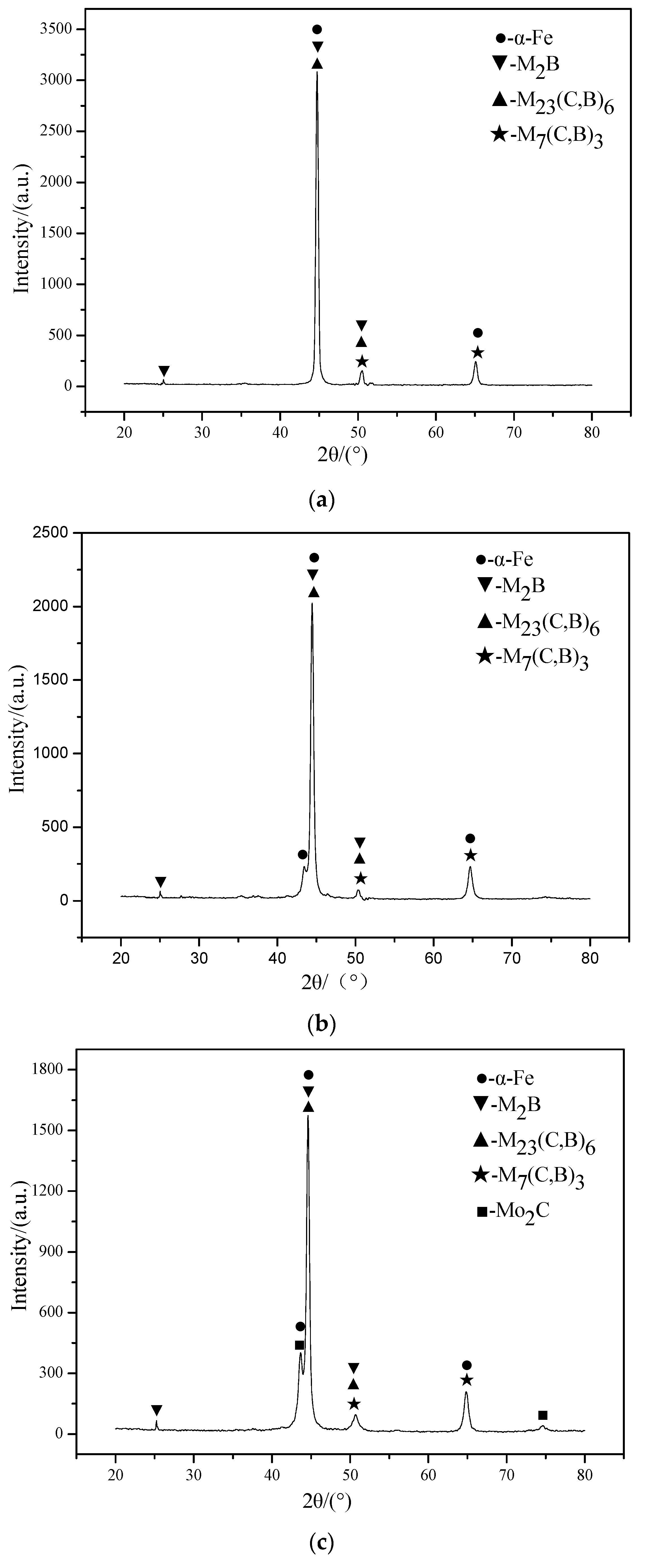
In order to identify the phase composition of the coatings with different Mo contents, XRD analysis were conducted on the coating. The XRD spectra are presented in Figure 2. With the increase of Mo content, the phases in the coating are changed and the intensity of the diffraction peak becomes weaker. The phases in the Mo-free coating are α-Fe, M2B (M = Fe, Ni), M23(C, B)6, and M7(C, B)3. Another α-Fe peak appears near the main peak when Mo is added into the coating. The intensity of the peak gradually increases with the increase of Mo content. When the Mo content is 4.0 wt. %, Mo2C phase appears in the coating. With the increase of Mo content, the amount of M7(C, B)3 decreases gradually, and the amount of M2B, M23(C, B)6, and Mo2C gradually increases.
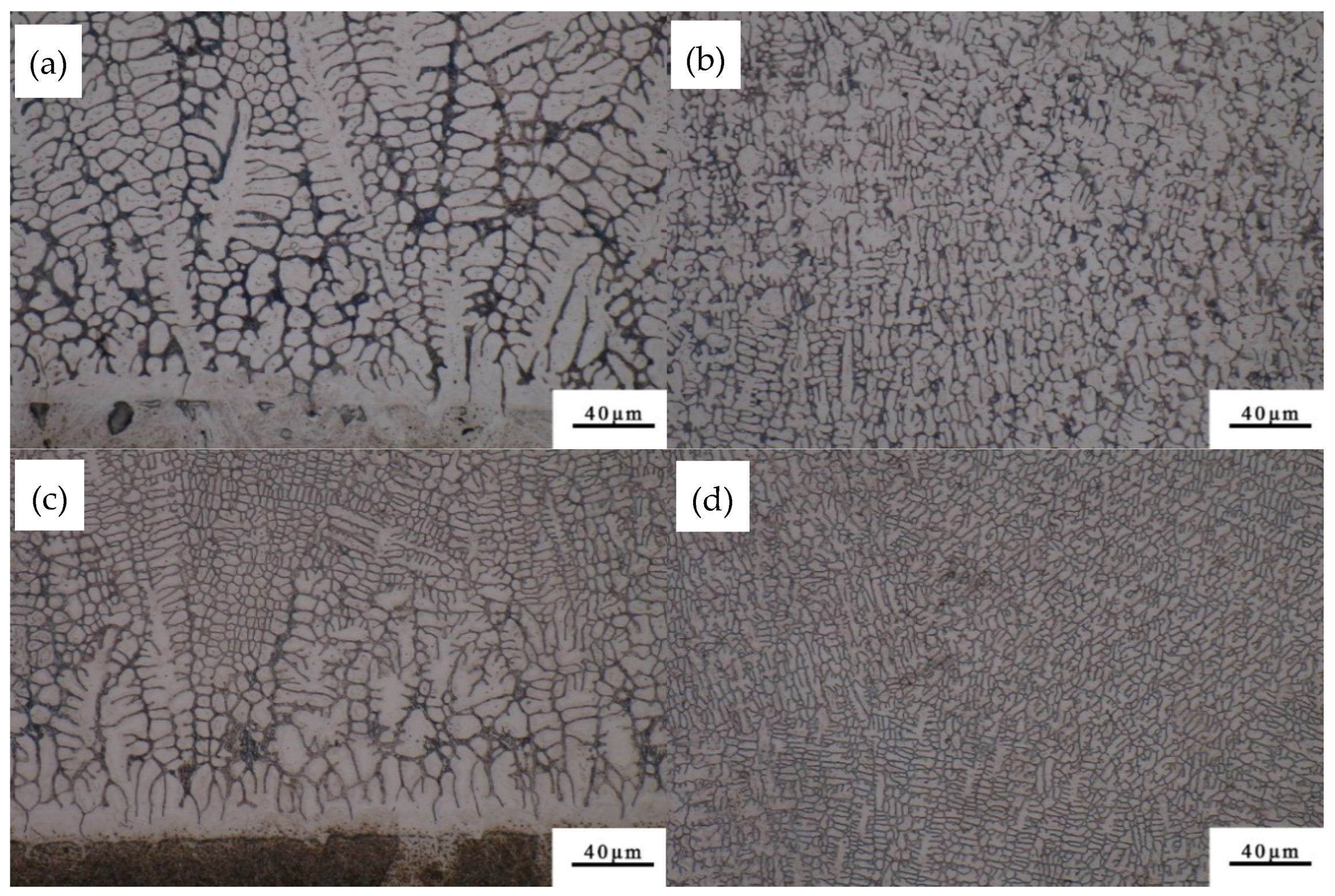
Figure 3 shows the metallographic microstructure of the coating. It can be seen from the bottom part of the coating (Figure 3a,c) that a light line is formed between the coating and the substrate. The light line is the fusion that grows mainly in the form of planar grains. The fusion line indicates a good metallurgical bonding between the substrate and the coating. During the solidification process, the microstructure of the coating is mainly determined by the ratio (G/R) of the temperature gradient (G) and solidification rate (R) [35]. The temperature gradient (G) is high and the solidification rate (R) is very low at the bottom of the molten pool, so the ratio of G/R is relatively large and the solidification structure grows as planar grains [36]. With the increase of distance from the fusion line, the temperature gradient (G) decreases and the solidification rate (R) increases, so that the G/R value is reduced, and the microstructure of the coating is transformed from planar grains to cell grains, dendrites, and equiaxed grains [37].
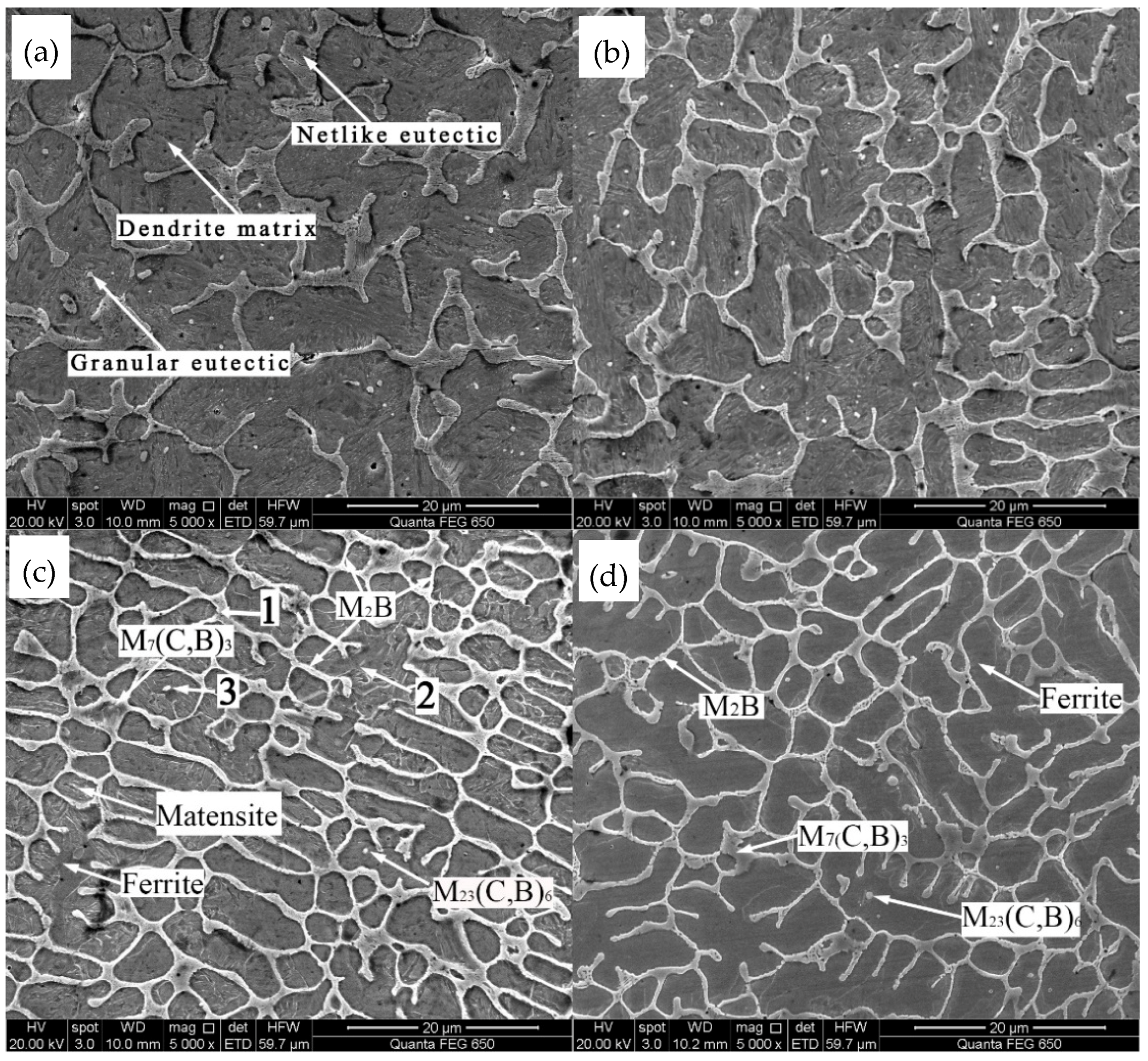
Figure 4 shows the scanning electron micrographs of the coating with different Mo contents. It can be seen from Figure 4 that the coating is mainly composed of a netlike eutectic structure, small granular eutectic structure, and dendrite matrix. During the solidification process, the dendrite matrix is firstly precipitated from the liquid phase, and then the eutectic structure between the dendrites is formed through the eutectic reaction in the remaining liquid phase. The size of the dendrite is obviously refined with the increase of Mo content from 0 to 6.0 wt. %, as shown in Figure 4. The sizes of the dendrite are measured by Image Pro-plus 6.0 software, and the average sizes of dendrites in the coatings of Mo-free, 2.0 wt. % Mo, 4.0 wt. % Mo, and 6.0 wt. % Mo are 7.9 μm, 6.5 μm, 4.4 μm, and 3.9 μm, respectively. This may result from the addition of Mo, which affects the nucleation process of the coating [38]. On the one hand, the Mo element can prevent the growth of austenite, which can refine the structure of the coating. On the other hand, part of Mo can dissolve in the coating, which results in lattice distortion. The compositions of netlike eutectic structure 1, the dendrite structure 2, and the granular eutectic structure 3 with the addition of 4.0 wt. % Mo content (Figure 4c) are analyzed by EPMA point scanning. The results are shown in Table 2. The EPMA results show that the contents of Cr, B, and C in the eutectic structure are relatively high. Combined with XRD results, it can be concluded that the netlike eutectic structures are mainly composed of M2B and M7(C, B)3. The content of Fe in the dentrite is the highest, indicating that the dentrite structures are mainly composed of martensite and ferrite. From Figure 4 it can also be seen that the amount of martensite decreases, while the amount of ferrite gradually increases with the increase of Mo content. This is because Mo can promote the formation of ferrite [39]. Dendrite 2 contains a certain amount of Cr, which can strengthen the matrix by solid solution strengthening [40]. According to the EPMA and XRD results, the content of C in the granular eutectic structure is higher, and the granular eutectic structure is therefore identified as M23(C, B)6.
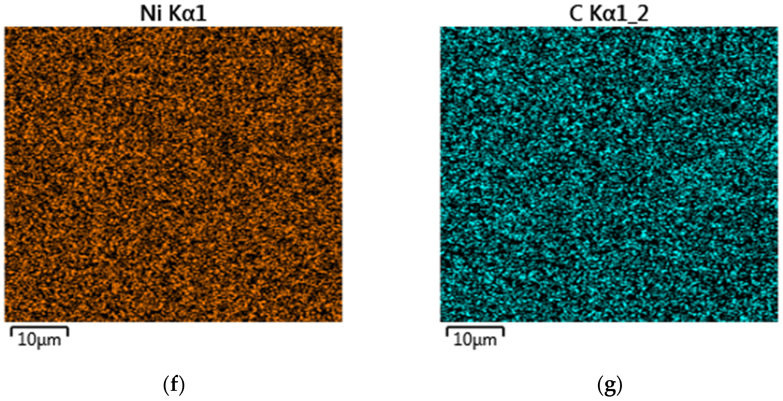
Figure 5 presents the mapping scanning results of 4.0 wt. % Mo coating. It shows that the microstructures are inhomogeneous due to the severe elemental segregation that occurs during solidification. As can be seen from Figure 5b, e , f, the Ni, Fe, and Si elements are evenly distributed in the matrix phase. The Mo, Cr, and C elements (showed in Figure 5c,d,g, respectively) are rich at the grain boundaries, which indicates that the microstructures of the grain boundaries are primarily carbides of Mo and Cr. EDS component analyses were done in this area, and the relative contents (wt. %) of the composition calculated are as follows: 72.7% Fe, 15.2% Cr, 4.6% Mo, 5.2% C, 0.7% Si, and 1.6% Ni.
3.2. Hardness Analysis
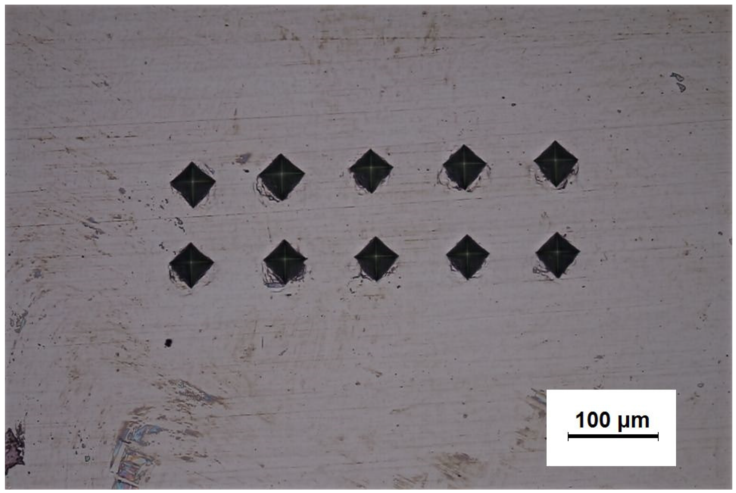
Figure 6 shows the morphology of the 4.0 wt. % Mo coating after the microhardness test. The size of the rhombus is basically the same, which indicates that the hardness distribution in the coating is uniform. The coating has good ductility because there are no obvious cracks around the indentations [41].
The microhardness test results of the coatings with different Mo contents are shown in Figure 7. The microhardness decreases with the increase of Mo content in the coatings. The microhardness of the 6.0 wt. % Mo coating is 288.0 HV, which is about half of the microhardness of the Mo-free coating. The XRD results show that the amount of M23(C, B)6 increases and the contents of M7(C, B)3 decrease with the addition of the Mo element. The microstructure analyses show that the martensite decreases and the ferrite increases gradually with the increase of Mo content in the coating. It is known from the literature that the microhardness of martensite is 525.4 HV and the microhardness of ferrite is 235.1 HV [42]. The microhardness of Cr23C6 is 13.2 GPa and the microhardness of Cr7C3 is 18.3 GPa [43]. Therefore, the microhardness of the coating decreases gradually with the increase of Mo content.
3.3. Wear Resistance
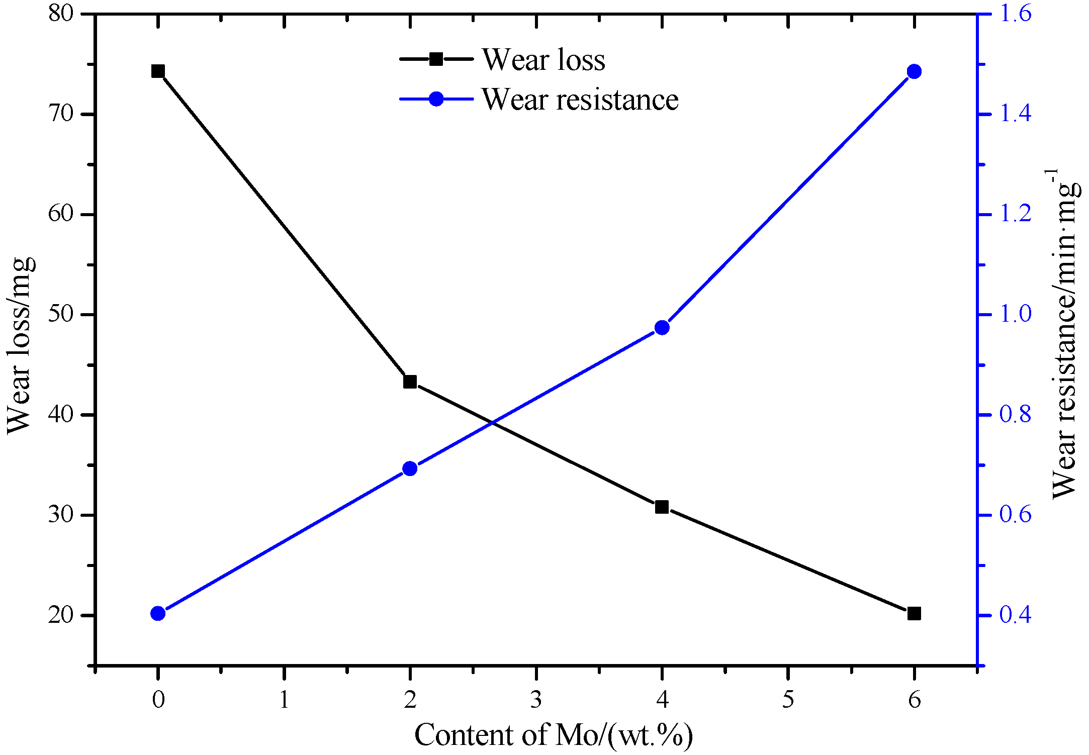
The wear loss and wear resistance of the coatings with different Mo contents are shown in Figure 8. The wear loss of the coatings decreases gradually with the increase of Mo content. The wear resistance of the 6.0 wt. % Mo coating is the best, which is about 3.7 times of that of Mo-free coating. Obviously, the addition of Mo in the stainless steel powder can greatly improve the wear resistance of the coatings.
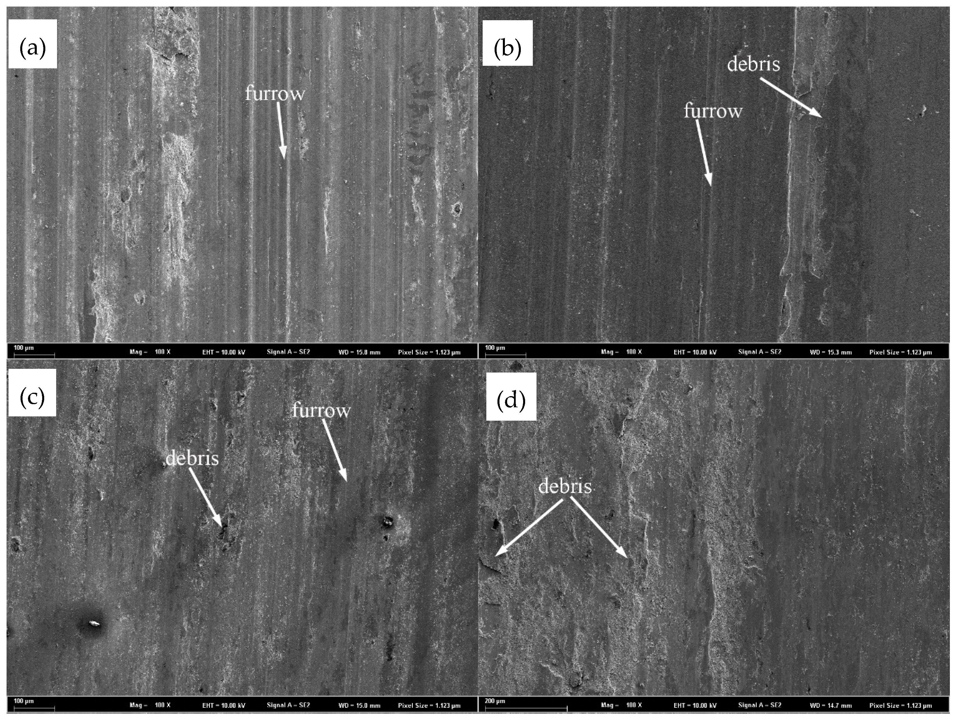
To reveal the wear mechanism of the coatings with different Mo contents, the worn morphologies of the coatings are observed by SEM, as shown in Figure 9. The worn surface of the Mo-free coating (Figure 9a) has a large number of deep furrows, which are typical features caused by abrasive wear. When the contents of Mo are 2 wt. % and 4 wt. % (Figure 9b,c), the depths of the furrows are reduced and the amount of debris is gradually increased. Both abrasive wear and adhesive wear exist for these two cases. When the Mo content is increased to 6 wt. %, there is no furrow on the worn surface, but there is a large amount of debris. The main wear mechanism is adhesive wear. From the above analysis we can see that when the Mo content in the stainless steel coating increases, the wear mechanism of the coating changes from abrasive wear to adhesive wear.
In summary, the wear resistance of the stainless steel coating can be improved by adding the Mo element. The main reasons for the increase of wear resistance of the coatings are as follows. First, from the microstructure analysis it can be seen that the addition of Mo will refine the microstructure of the coatings, which can improve the wear resistance of the coating [44]. Second, the addition of Mo can change the phase types of the stainless steel coatings from the XRD results. Mo2C hard phase is formed when the Mo content is greater than 4 wt. %. Therefore, the wear resistance of the coatings can be effectively improved with the increase of Mo [45]. Third, a higher hardness generally represents a higher brittleness and lower ductility, and the lower hardness shown in Figure 6 therefore represents a ductility of the coating when Mo is added [46]. With the increase of Mo content, the hardness of the coating will decreases, and the ductility will increase. The increase of ductility will increase the wear resistance of the coatings [47]. Fourth, it is found from the worn morphologies that the depths of the furrows on the coating surfaces gradually decrease while the amounts of debris increase with the increase of Mo content. Such changes indicate that the wear mechanism is changed from abrasive wear to adhesive wear with the increase of Mo content. Therefore, the wear resistance of the coating is improved with the increase of Mo content.
3.4. Electrochemical Test Analysis
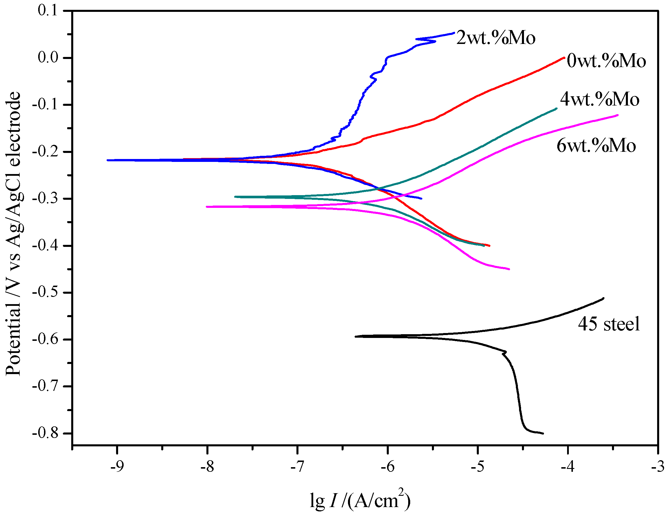
The potentiodynamic polarization curves of the coatings with different Mo contents and 45 steel substrate are shown in Figure 10. The potential for all of the coatings is higher than that of the 45 steel substrate, which indicates that the corrosion resistance of the 45 steel substrate is significantly improved by the coatings. Laser cladding is a rapid heating and cooling process. From the XRD results, it can be seen that complex chemical reactions take place and new phases generate during the solidification process. The addition of Mo will refine the microstructure of the coatings, which can improve the corrosion resistance of the coating. With the increase of Mo content in the coatings, the potential first increases and then decreases. The coating with 2.0 wt. % Mo has the best corrosion resistance. The reasons are as follows. When the corrosion test is carried out in NaCl solution, the Cl− will be adsorbed on the surface of the coating, which can react with the metal ion and form soluble chloride. This process can break the surface of the coating, and result in the formation of pitting (i.e., corrosion) on the surface of the coating. The addition of Mo can lead to a passivation phenomenon and greatly improve the pitting resistance of the coating [48]. When a certain amount of Mo is added in the coating, it can form a passivation film on the surface of the coating, which hinders the Cl− entering the coating. So the pitting of the coating reduces and the corrosion resistance improves. When the Mo content is too high, the corrosion resistance decreases. Through the mapping scanning analysis, it can be seen that the Mo element is mainly enriched at the grain boundaries. Such an uneven distribution reduces the corrosion resistance of the coating.
4. Conclusions
The stainless steel coatings with different Mo contents were prepared on the surface of a 45 steel substrate by laser cladding. The following conclusions can be obtained.
- (1)
- With the increase of Mo content, the amount of M7(C, B)3 decreases gradually, while the amount of M2B, M23(C, B)6, and Mo2C gradually increases. When the Mo content is 4.0 wt. % and above, Mo2C phase appears in the coating.
- (2)
- The microstructure of the coatings is transformed from planar crystals to cell crystals, dendrites, and equiaxed crystals with the increase of distance from the fusion line. The amount of martensite decreases, while the amount of ferrite gradually increases with the increase of Mo content.
- (3)
- The microhardness decreases and the wear resistance of the coatings gradually increases with the increase of Mo content. The wear resistance of the 6.0 wt. % Mo coating is about 3.7 times that of the Mo-free coating.
- (4)
- The corrosion resistance of the 45 steel substrate is significantly improved by the laser cladding coating. With the increase of Mo content, the corrosion resistance of the coating first increases and then decreases. The coating with 2.0 wt. % Mo has the best corrosion resistance.
Acknowledgments
The authors appreciate the financial support for this work from National Natural Science Foundation of China (No. 51675303), the Open Foundation of Key Laboratory of E&M (Zhejiang University of Technology), Ministry of Education & Zhejiang Province (No. EM2016070103), and the Tribology Science Fund of the State Key Laboratory of Tribology (SKLT2014B09, SKLT2015B09).
Author Contributions
Kaiming Wang performed all experiments and wrote the paper; Baohua Chang and Hanguang Fu designed the experiments and reviewed the paper; Jiongshen Chen and Yinghua Lin performed the experiments; Yongping Lei analyzed the data.
Conflicts of Interest
The authors declare no conflict of interest.
References
- Vera, R.; Rosales, B.M.; Tapia, C. Effect of the exposure angle in the corrosion rate of plain carbon steel in a marine atmosphere. Corros. Sci. 2003, 45, 321–337. [Google Scholar] [CrossRef]
- Storojeva, L.; Ponge, D.; Kaspar, R.; Raabe, D. Development of microstructure and texture of medium carbon steel during heavy warm deformation. Acta. Mater. 2004, 52, 2209–2220. [Google Scholar] [CrossRef]
- Yang, Y.W.; Fu, H.G.; Lei, Y.P.; Wang, K.M.; Zhu, L.L.; Jiang, L. Phase Diagram Calculation and Analyze on Cast High-Boron High-Speed Steel. J. Mater. Eng. Perform. 2015, 25, 409–420. [Google Scholar] [CrossRef]
- Kolman, D.G. A review of the potential environmentally assisted failure mechanisms of austenitic stainless steel storage containers housing stabilized radioactive compounds. Corros. Sci. 2001, 43, 99–125. [Google Scholar] [CrossRef]
- Ronkainen, H.; Varjus, S.; Holmberg, K. Friction and wear properties in dry, water-and oil-lubricated DLC against alumina and DLC against steel contacts. Wear 1998, 222, 120–128. [Google Scholar] [CrossRef]
- Gao, H.; Jiao, X.; Zhou, C.; Shen, Q.; Yu, Y. Study on Remote Control Underwater Welding Technology Applied in Nuclear Power Station. Proc. Eng. 2011, 15, 4988–4993. [Google Scholar] [CrossRef]
- Birger, E.M.; Moskvitin, G.V.; Polyakov, A.N.; Arkhipov, V.E. Industrial laser cladding: Current state and future. Weld. Int. 2011, 25, 234–243. [Google Scholar] [CrossRef]
- Simunovic, K.; Saric, T.; Simunovic, G. Different Approaches to the Investigation and Testing of the Ni-Based Self-Fluxing Alloy Coatings—A Review. Part 1: General Facts, Wear and Corrosion Investigations. Tribol. Trans. 2014, 57, 955–979. [Google Scholar] [CrossRef]
- Han, B.; Li, M.; Wang, Y. Microstructure and Wear Resistance of Laser Clad Fe-Cr3C2 Composite Coating on 35CrMo Steel. J. Mater. Eng. Perform. 2013, 22, 3749–3754. [Google Scholar] [CrossRef]
- Grum, J.; Žnidaršič, M. Microstructure, Microhardness, and Residual Stress Analysis of Laser Surface Cladding of Low-Carbon Steel. Mater. Manuf. Process. 2004, 19, 243–258. [Google Scholar] [CrossRef]
- Zhao, W.; Zha, G.C.; Kong, F.X.; Wu, M.L.; Feng, X.; Gao, S.Y. Strengthening Effect of Incremental Shear Deformation on Ti Alloy Clad Plate with a Ni-Based Alloy Laser-Clad Layer. J. Mater. Eng. Perform. 2017, 26, 2411–2416. [Google Scholar] [CrossRef]
- Paatsch, W. Energy turnaround—A challenge for surface technology. Trans. Inst. Met. Finish. 2016, 94, 228–230. [Google Scholar] [CrossRef]
- Tan, H.; Luo, Z.; Li, Y.; Yan, F.; Duan, R.; Huang, Y. Effect of strengthening particles on the dry sliding wear behavior of Al2O3–M7C3/Fe metal matrix composite coatings produced by laser cladding. Wear 2015, 324–325, 36–44. [Google Scholar] [CrossRef]
- Ray, A.; Arora, K.S.; Lester, S.; Shome, M. Laser cladding of continuous caster lateral rolls: Microstructure, wear and corrosion characterisation and on-field performance evaluation. J. Mater. Process. Technol. 2014, 214, 1566–1575. [Google Scholar] [CrossRef]
- Peng, H.; Li, R.; Yuan, T.; Wu, H.; Yan, H. Producing nanostructured Co–Cr–W alloy surface layer by laser cladding and friction stir processing. J. Mater. Res. 2015, 30, 717–726. [Google Scholar] [CrossRef]
- Xu, G.J.; Kutsuna, M. Cladding with Stellite 6 + WC using a YAG laser robot system. Surf. Eng. 2013, 22, 345–352. [Google Scholar] [CrossRef]
- Gao, W.; Zhao, S.; Liu, F.; Wang, Y.; Zhou, C.; Lin, X. Effect of defocus manner on laser cladding of Fe-based alloy powder. Surf. Coat. Technol. 2014, 248, 54–62. [Google Scholar] [CrossRef]
- Zeng, Q.; Sun, J.; Emori, W.; Jiang, S.L. Corrosion Behavior of Thermally Sprayed NiCrBSi Coating on 16MnR Low-Alloy Steel in KOH Solution. J. Mater. Eng. Perform. 2016, 25, 1773–1780. [Google Scholar] [CrossRef]
- Zhou, S.; Dai, X.; Zheng, H. Microstructure and wear resistance of Fe-based WC coating by multi-track overlapping laser induction hybrid rapid cladding. Opt. Laser. Technol. 2012, 44, 190–197. [Google Scholar] [CrossRef]
- Qu, S.; Wang, X.; Zhang, M.; Zou, Z. Microstructure and wear properties of Fe–TiC surface composite coating by laser cladding. J. Mater. Sci. 2008, 43, 1546–1551. [Google Scholar] [CrossRef]
- Zhou, S.; Dai, X.; Xiong, Z.; Wu, C.; Zhang, T.; Zhang, Z. Influence of Al addition on microstructure and properties of Cu–Fe-based coatings by laser induction hybrid rapid cladding. J. Mater. Res. 2014, 29, 865–873. [Google Scholar] [CrossRef]
- Wang, Y.; Zhao, S.; Gao, W.; Zhou, C.; Liu, F.; Lin, X. Microstructure and properties of laser cladding FeCrBSi composite powder coatings with higher Cr content. J. Mater. Process. Technol. 2014, 214, 899–905. [Google Scholar] [CrossRef]
- Lei, Y.; Sun, R.; Lei, J.; Tang, Y.; Niu, W. A new theoretical model for high power laser clad TiC/NiCrBSiC composite coatings on Ti6Al4V alloys. Opt. Lasers Eng. 2010, 48, 899–905. [Google Scholar] [CrossRef]
- Xu, J.S.; Zhang, X.C.; Xuan, F.Z.; Wang, Z.D.; Tu, S.T. Microstructure and Sliding Wear Resistance of Laser Cladded WC/Ni Composite Coatings with Different Contents of WC Particle. J. Mater. Eng. Perform. 2011, 21, 1904–1911. [Google Scholar] [CrossRef]
- Qu, K.L.; Wang, X.H.; Wang, Z.K.; Niu, W.Y. Effect of Mo on the VC–VB particles reinforced Fe-based composite coatings. Mater. Sci. Technol. 2016, 33, 333–339. [Google Scholar] [CrossRef]
- Ma, Q.S.; Li, Y.J.; Wang, J. Effects of Ti addition on microstructure homogenization and wear resistance of wide-band laser clad Ni60/WC composite coatings. Int. J. Refract. Met. Hard. Mater. 2017, 64, 225–233. [Google Scholar]
- Lin, Y.; Lei, Y.; Fu, H.; Lin, J. Mechanical properties and toughening mechanism of TiB2/NiTi reinforced titanium matrix composite coating by laser cladding. Mater. Des. 2015, 80, 82–88. [Google Scholar] [CrossRef]
- Zhang, G.Y.; Wang, C.L.; Gao, Y. Mechanism of Rare Earth CeO2 on the Ni-Based Laser Cladding Layer of 6063 Al Surface. Rare Met. Mater. Eng. 2016, 45, 1002–1006. [Google Scholar]
- Weng, F.; Yu, H.; Chen, C.; Liu, J.; Zhao, L. Microstructures and properties of TiN reinforced Co-based composite coatings modified with Y2O3 by laser cladding on Ti–6Al–4V alloy. J. Alloys Compd. 2015, 650, 178–184. [Google Scholar] [CrossRef]
- Hou, Q.Y.; He, Y.Z.; Zhang, Q.A.; Gao, J.S. Influence of molybdenum on the microstructure and wear resistance of nickel-based alloy coating obtained by plasma transferred arc process. Mater. Des. 2007, 28, 1982–1987. [Google Scholar] [CrossRef]
- Wang, X.H.; Han, F.; Liu, X.M.; Qu, S.Y.; Zou, Z.D. Effect of molybdenum on the microstructure and wear resistance of Fe-based hardfacing coatings. Mater. Sci. Eng. A. 2008, 489, 193–200. [Google Scholar] [CrossRef]
- Ding, L.; Hu, S.; Quan, X.; Shen, J. Effect of Mo and nano-Nd2O3 on the microstructure and wear resistance of laser cladding Ni-based alloy coatings. Appl. Phys. A Mater. 2016, 122, 288. [Google Scholar] [CrossRef]
- Wang, K.M.; Fu, H.G.; Lei, Y.P.; Yang, Y.W.; Li, Q.T.; Su, Z.Q. Microstructure and property of Ni60A/WC composite coating fabricated by fiber laser cladding. Materialwiss. Werkstofftech. 2015, 46, 1177–1184. [Google Scholar] [CrossRef]
- Li, Q.; Lei, Y.; Fu, H. Growth mechanism, distribution characteristics and reinforcing behavior of (Ti, Nb)C particle in laser cladded Fe-based composite coating. Appl. Surf. Sci. 2014, 316, 610–616. [Google Scholar] [CrossRef]
- Kurz, W.; Giovanola, B.; Trivedi, R. Theory of microstructural development during rapid solidification. Acta. Metall. 1986, 34, 823–830. [Google Scholar] [CrossRef]
- Bansal, A.; Zafar, S.; Sharma, A.K. Microstructure and Abrasive Wear Performance of Ni-Wc Composite Microwave Clad. J. Mater. Eng. Perform. 2015, 24, 3708–3716. [Google Scholar] [CrossRef]
- Liu, Z.; Qi, H. Effects of substrate crystallographic orientations on crystal growth and microstructure formation in laser powder deposition of nickel-based superalloy. Acta Mater. 2015, 87, 248–258. [Google Scholar] [CrossRef]
- Li, B.; Jin, Z.; Ren, H.; Zhang, L.; Qu, W. Effect of molybdenum on microstructure and properties of low alloy high strength steel. Heat Treat. Met. 2016, 41, 145–147. [Google Scholar]
- Shin, J.C.; Doh, J.M.; Yoon, J.K.; Lee, D.Y.; Kim, J.S. Effect of molybdenum on the microstructure and wear resistance of cobalt-base Stellite hardfacing alloys. Surf. Coat. Technol. 2003, 166, 117–126. [Google Scholar] [CrossRef]
- Jarrett, R.N.; Tien, J.K. Effects of cobalt on structure, microchemistry and properties of a wrought nickel-base superalloy. Metall. Trans. A 1982, 13, 1021–1032. [Google Scholar] [CrossRef]
- Li, B.; Jin, Y.; Yao, J.; Li, Z.; Zhang, Q. Solid-state fabrication of WC p-reinforced Stellite-6 composite coatings with supersonic laser deposition. Surf. Coat. Technol. 2017, 321, 386–396. [Google Scholar] [CrossRef]
- Zhou, P.; Yang, L. Microstructure of 10CrMnMo dual-phase steel under different intercritical quenching temperature. Heat Treat. Met. 2017, 42, 110–114. [Google Scholar]
- Min, T.; Gao, Y.; Li, Y.; Yang, Y.; Li, R.; Xie, X. First-Principles Calculations Study on the Electronic Structures, Hardness and Debye Temperatures of Chromium Carbides. Rare Met. Mater. Eng. 2012, 41, 271–275. [Google Scholar]
- Hou, Q.Y.; He, Y.Z.; Gao, J.S. Microstructure and wear resistance of Mo /Ni-based alloy coating produced by plasma cladding. Chin. J. Nonferrous Met. 2006, 16, 1595–1602. [Google Scholar]
- Xiong, Z.; Xu, Q.; He, Q.; Wang, Y. The effect of Mo content on the organization and the performance of the hypoeutectic high carbon, high chromium alloy. Electr. Weld. Mach. 2016, 46, 59–62. [Google Scholar]
- Liu, Z.J.; Liu, C.; Chen, H.; Li, Y.K.; Cheng, J.B.; Su, Y.H.; Liu, D. Impact wear-resistant hardfacing austenitic material. Trans. China Weld. Inst. 2005, 26, 9–12. [Google Scholar]
- Hu, Y.W.; Yin, Y.S. Analysis of affecting factors of wearing resistance of surfacing layer. J. Shenyang Univ. Technol. 2002, 24, 386–388. [Google Scholar]
- Li, D.; Zhou, F.; Yu, S. Microstructure and corrosion resistance of FeCrNiMnMoxB0.5 high entropy alloy coating prepared by laser cladding. High Power Laser Part. Beams 2016, 28, 1–6. [Google Scholar]
Figure 1.
Schematic diagram of wear tester. 1—Rotating ring, 2—The coating, 3—45 steel substrate, 4—Load.
Figure 1.
Schematic diagram of wear tester. 1—Rotating ring, 2—The coating, 3—45 steel substrate, 4—Load.
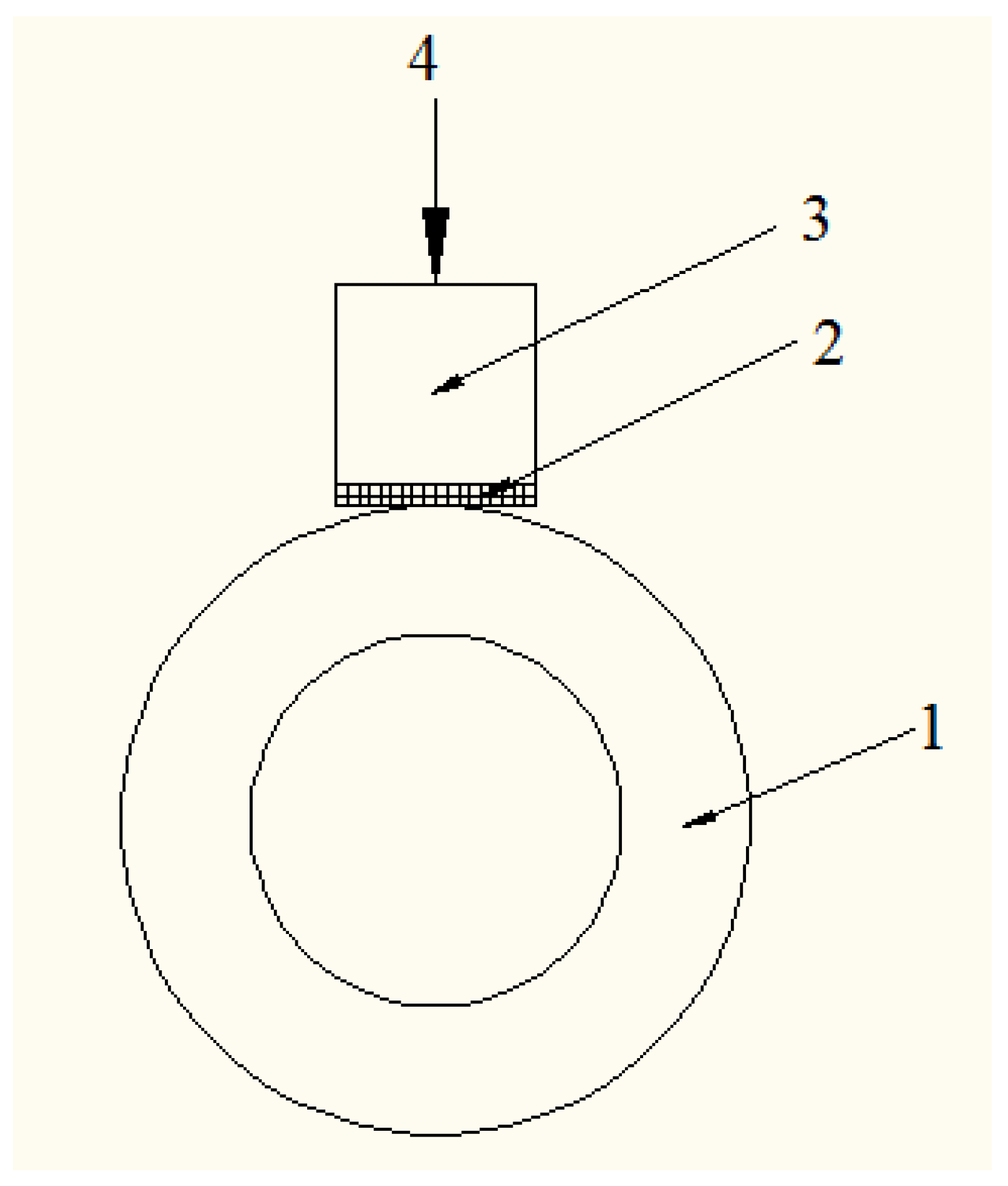
Figure 2.
XRD spectrums of coatings: (a) Mo-free; (b) 2.0 wt. % Mo; (c) 4.0 wt. % Mo; (d) 6.0 wt. % Mo.
Figure 2.
XRD spectrums of coatings: (a) Mo-free; (b) 2.0 wt. % Mo; (c) 4.0 wt. % Mo; (d) 6.0 wt. % Mo.

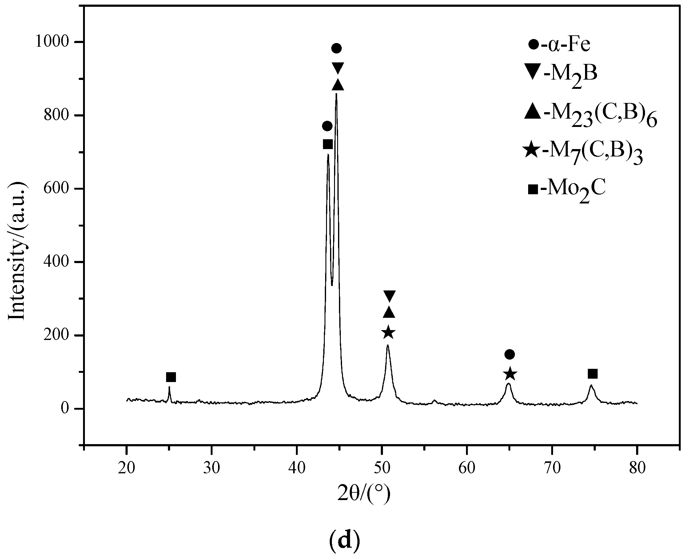
Figure 3.
Optical micrographs of the coating: (a) The bottom part of the Mo-free coating; (b) The upper part of the Mo-free coating; (c) The bottom part of the 4.0 wt. % Mo coating; (d) The upper part of the 4.0 wt. % Mo coating.
Figure 3.
Optical micrographs of the coating: (a) The bottom part of the Mo-free coating; (b) The upper part of the Mo-free coating; (c) The bottom part of the 4.0 wt. % Mo coating; (d) The upper part of the 4.0 wt. % Mo coating.

Figure 4.
Microstructure of coatings with different Mo content: (a) Mo-free; (b) 2.0 wt. % Mo; (c) 4.0 wt. % Mo; (d) 6.0 wt. % Mo.
Figure 4.
Microstructure of coatings with different Mo content: (a) Mo-free; (b) 2.0 wt. % Mo; (c) 4.0 wt. % Mo; (d) 6.0 wt. % Mo.

Figure 5.
The mapping scanning results of the 4 wt. % Mo coating: (a) surface scan diagram (b) Fe; (c) Cr; (d) Mo; (e) Si; (f) Ni; (g) C.
Figure 5.
The mapping scanning results of the 4 wt. % Mo coating: (a) surface scan diagram (b) Fe; (c) Cr; (d) Mo; (e) Si; (f) Ni; (g) C.
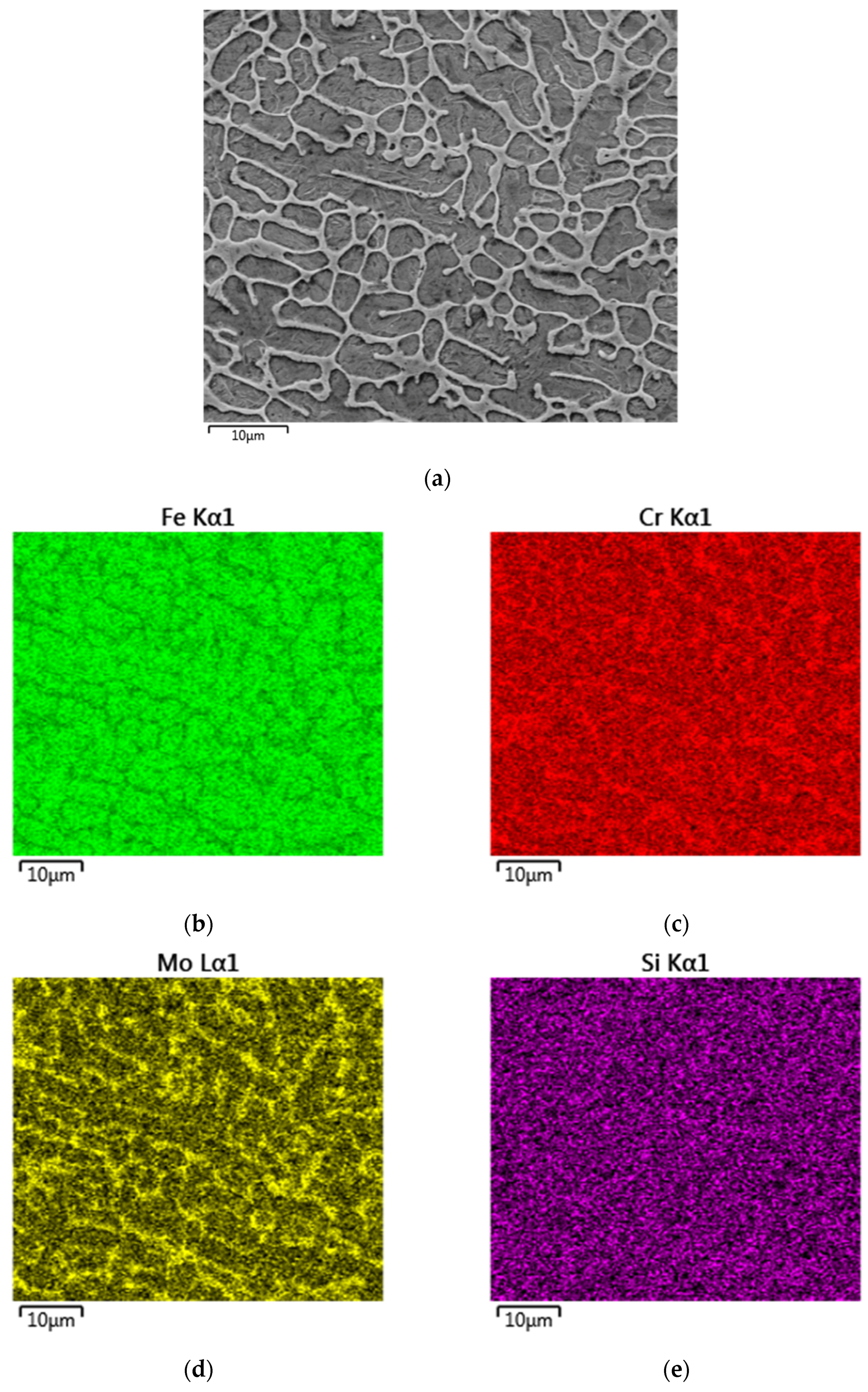

Figure 6.
Hardness indentation morphology of the coating (4.0 wt. % Mo).

Figure 7.
Effect of Mo content on the microhardness of the coating.
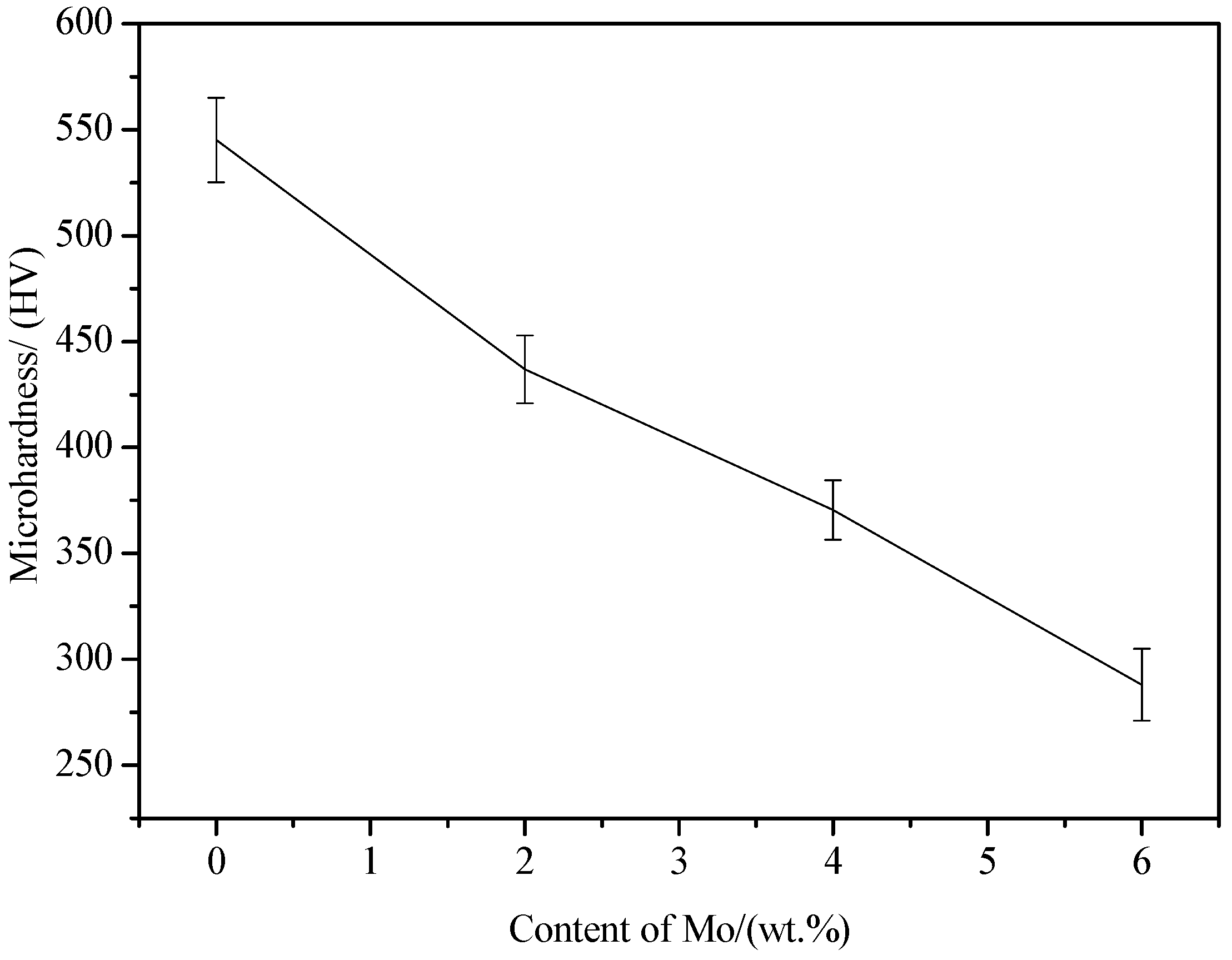
Figure 8.
Effect of Mo content on the wear loss and wear resistance of the coatings.

Figure 9.
Worn surfaces of laser cladding coatings with different Mo contents: (a) Mo-free; (b) 2.0 wt. % Mo; (c) 4.0 wt. % Mo; (d) 6.0 wt. % Mo.
Figure 9.
Worn surfaces of laser cladding coatings with different Mo contents: (a) Mo-free; (b) 2.0 wt. % Mo; (c) 4.0 wt. % Mo; (d) 6.0 wt. % Mo.

Figure 10.
Potentiodynamic polarization curves of the substrate and four coatings with different Mo contents.
Figure 10.
Potentiodynamic polarization curves of the substrate and four coatings with different Mo contents.

Table 1.
Chemical composition of the 45 steel substrate and 431 stainless steel alloy powder (wt. %).
Table 1.
Chemical composition of the 45 steel substrate and 431 stainless steel alloy powder (wt. %).
| Element | C | Cr | Ni | Si | Mn | B | Co | Fe |
|---|---|---|---|---|---|---|---|---|
| 45 steel | 0.44 | 0.15 | 0.15 | 0.24 | 0.69 | - | - | Bal. |
| 431 powder | 0.19 | 18.44 | 2.40 | 0.75 | 0.26 | 0.87 | 0.53 | Bal. |
Table 2.
The electron probe microanalyzer (EPMA) results of the point scan (wt. %).
| Point | Cr | C | B | Mo | Ni | Si | Fe |
|---|---|---|---|---|---|---|---|
| 1 | 19.978 | 4.877 | 4.789 | 4.674 | 1.910 | 0.428 | 63.344 |
| 2 | 15.336 | 2.606 | - | 1.801 | 1.937 | 0.783 | 77.537 |
| 3 | 14.224 | 11.034 | 0.139 | 1.780 | 1.697 | 0.779 | 70.347 |
© 2017 by the authors. Licensee MDPI, Basel, Switzerland. This article is an open access article distributed under the terms and conditions of the Creative Commons Attribution (CC BY) license (http://creativecommons.org/licenses/by/4.0/).
Share and Cite
MDPI and ACS Style
Wang, K.; Chang, B.; Chen, J.; Fu, H.; Lin, Y.; Lei, Y. Effect of Molybdenum on the Microstructures and Properties of Stainless Steel Coatings by Laser Cladding. Appl. Sci. 2017, 7, 1065. https://doi.org/10.3390/app7101065
AMA Style
Wang K, Chang B, Chen J, Fu H, Lin Y, Lei Y. Effect of Molybdenum on the Microstructures and Properties of Stainless Steel Coatings by Laser Cladding. Applied Sciences. 2017; 7(10):1065. https://doi.org/10.3390/app7101065
Chicago/Turabian StyleWang, Kaiming, Baohua Chang, Jiongshen Chen, Hanguang Fu, Yinghua Lin, and Yongping Lei. 2017. "Effect of Molybdenum on the Microstructures and Properties of Stainless Steel Coatings by Laser Cladding" Applied Sciences 7, no. 10: 1065. https://doi.org/10.3390/app7101065
Note that from the first issue of 2016, this journal uses article numbers instead of page numbers. See further details here.