
Development of a Robotic Arm Based Hydrogel Additive Manufacturing System for In-Situ Printing

Abstract
:1. Introduction
2. Robotic Arm Printing Platform
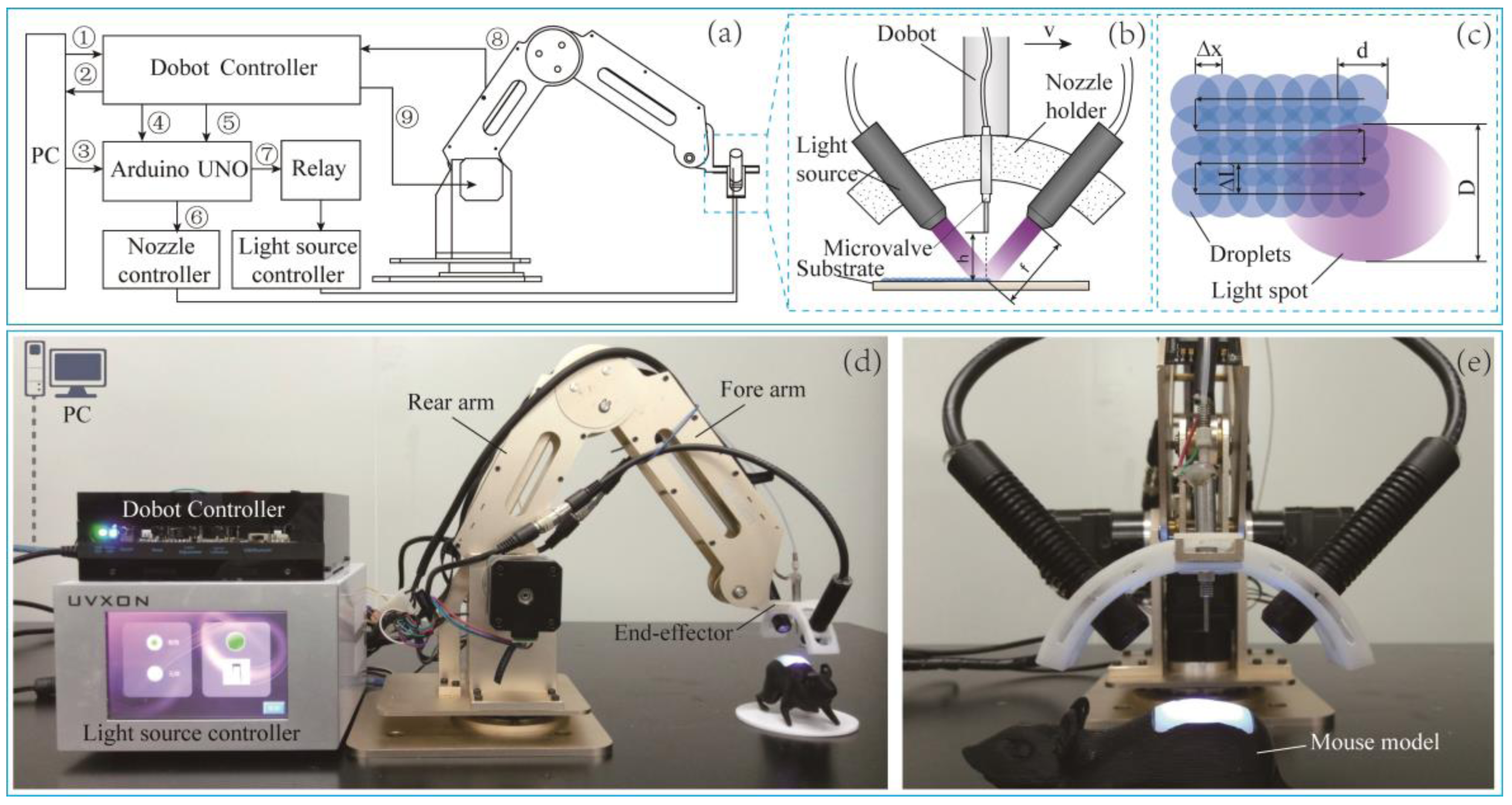
2.1. Hardware
2.2. Nozzle
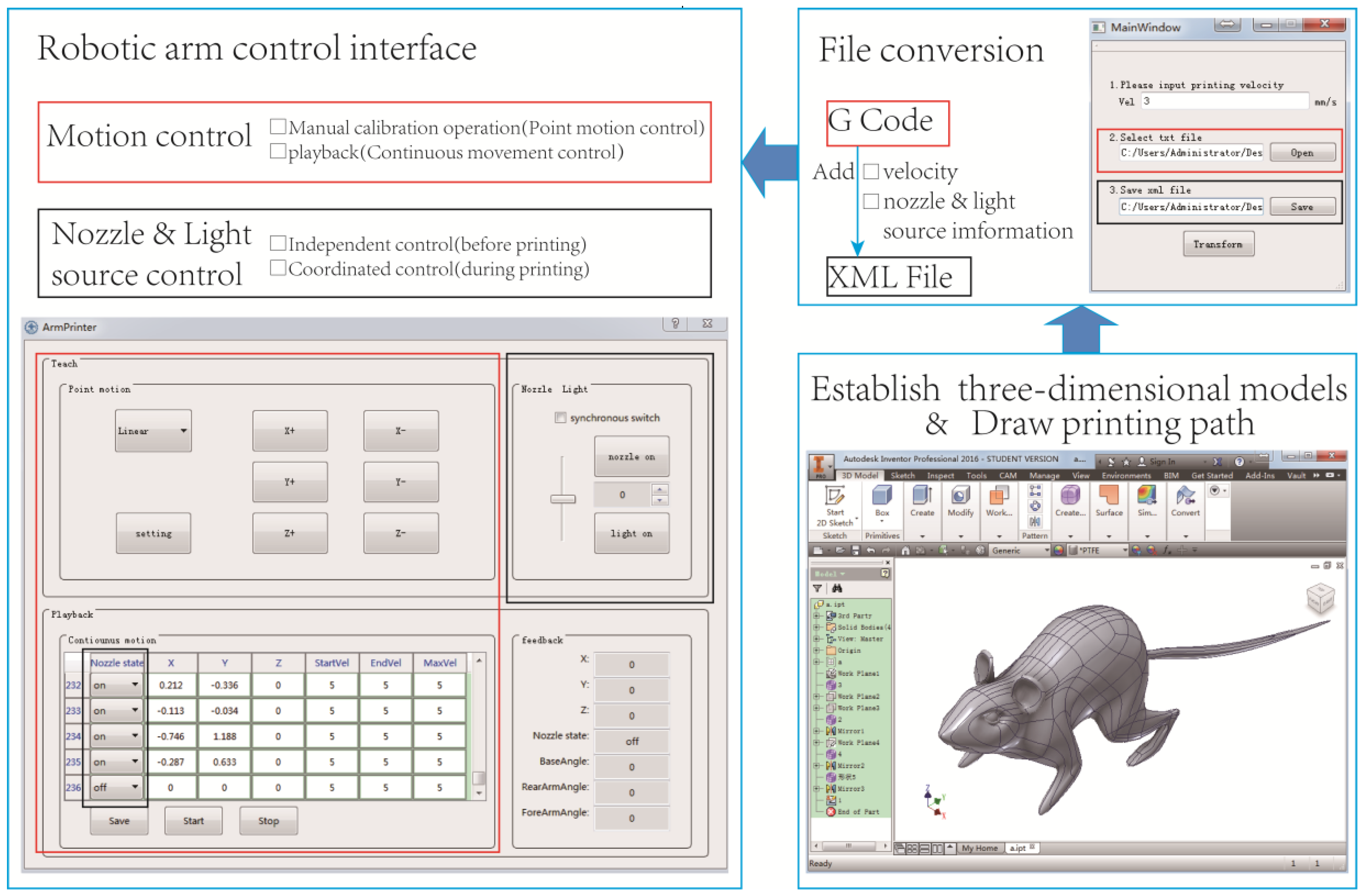
2.3. Software
3. Forming Process
3.1. Materials
3.2. Methods
3.2.1. Measurement of Droplet Diameter
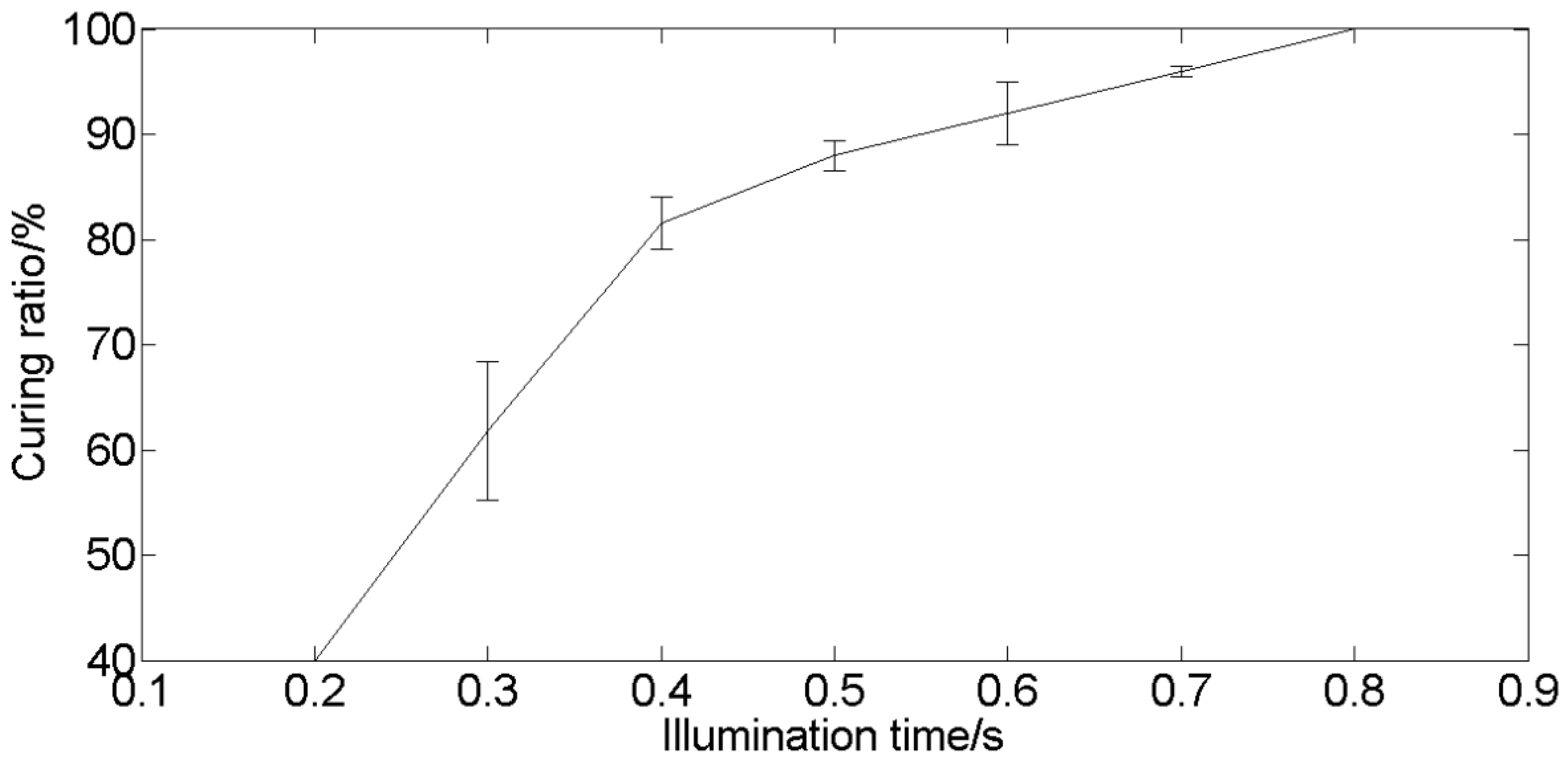
3.2.2. Measurement of Curing Time
3.2.3. Initial Printing Trials
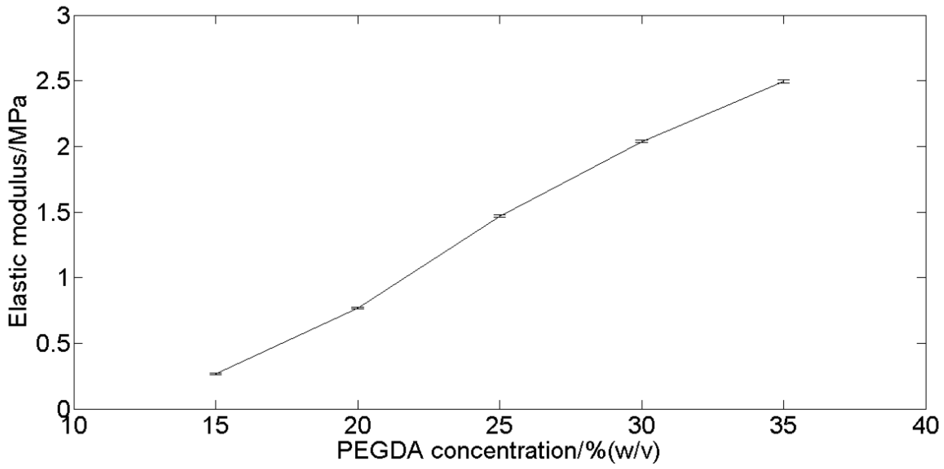
3.2.4. Mechanical Testing
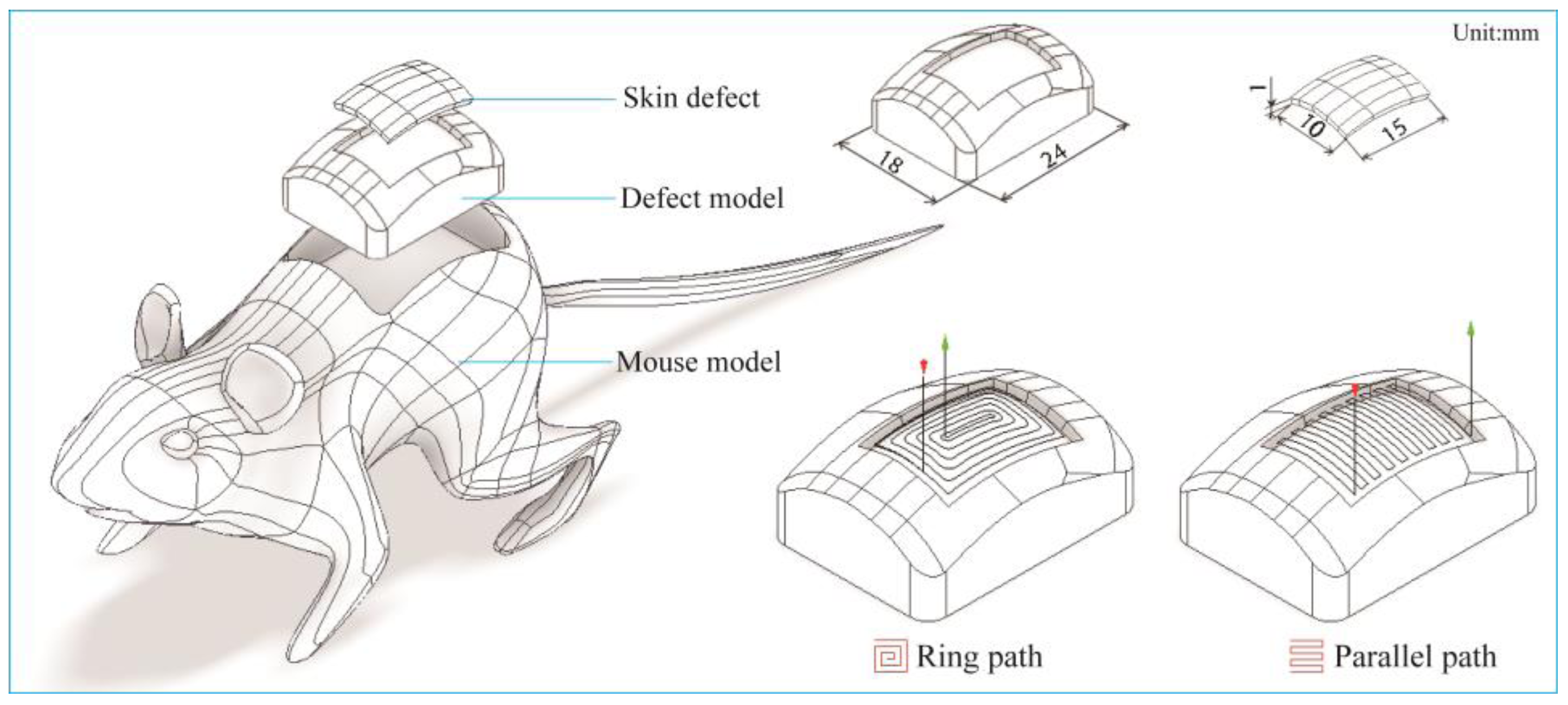
3.2.5 In-situ Printing Experiment
3.3. Results
3.3.1. Droplet Diameter
3.3.2. Curing Time
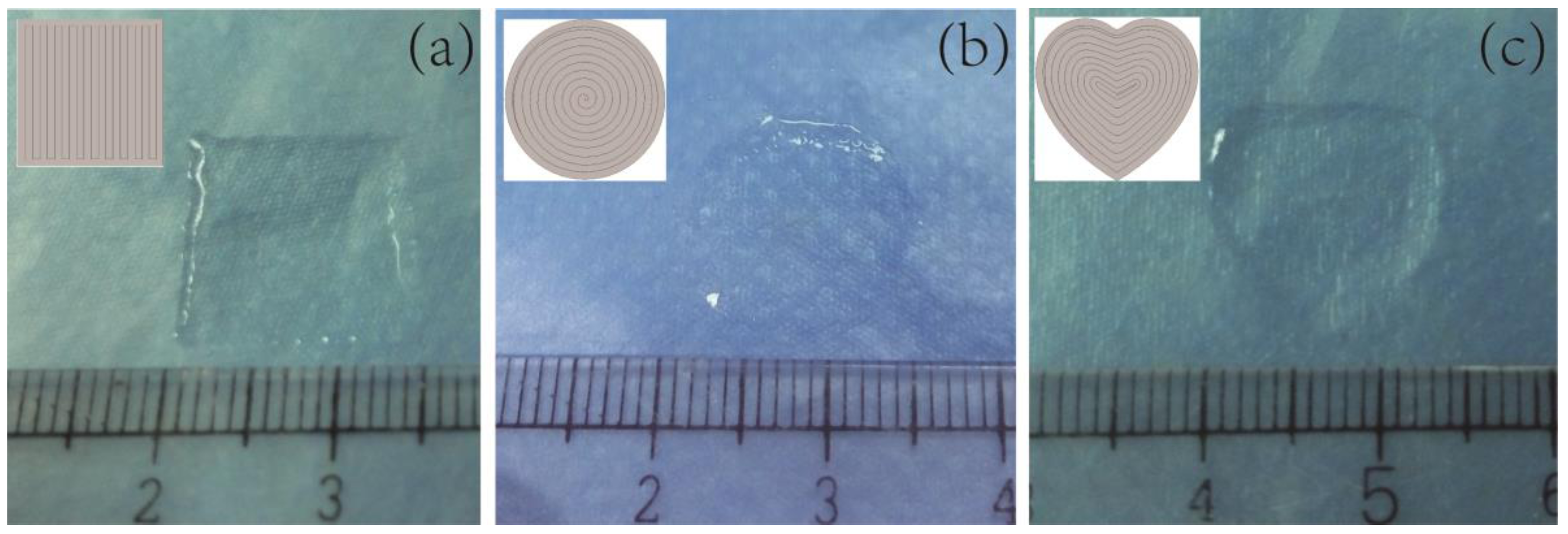
3.3.3. Initial Printing Trials
3.3.4. Mechanical Testing
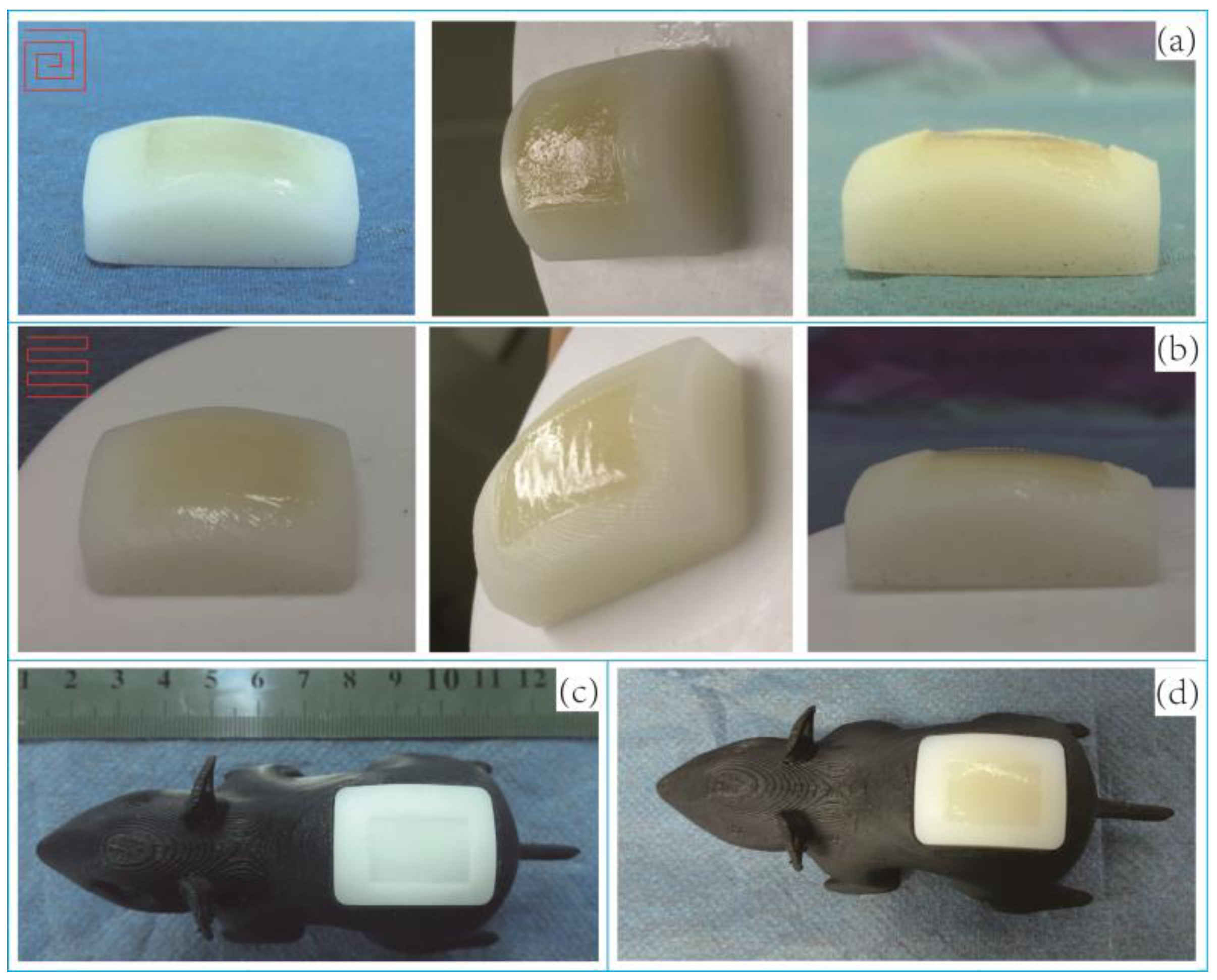
3.3.5. In-Situ Printing
4. Discussion
5. Conclusions
Supplementary Materials
Acknowledgments
Author Contributions
Conflicts of Interest
References
- Chen, D.; Liu, Y.; He, J.; Wang, Z.; Jin, Z. Research Status and Future of In-Situ Three-Dimensional Printing Technique. Chin. J. Reparative Reconstr. Surg. 2014, 28, 1428–1430. [Google Scholar]
- Ozbolat, I.T. Bioprinting Scale-Up Tissue and Organ Constructs for Transplantation. Trends Biotechnol. 2015, 33, 395–400. [Google Scholar] [CrossRef] [PubMed]
- Binder, K.W. In-Situ Bioprinting of the Skin. Ph.D. Thesis, Wake Forest University, Winston-Salem, NC, USA, 2011. [Google Scholar]
- Cui, X.; Breitenkamp, K.; Finn, M.G.; Lotz, M.; D’Lima, D.D. Direct Human Cartilage Repair Using Three-Dimensional Bioprinting Technology. Tissue Eng. A 2012, 18, 1304–1312. [Google Scholar] [CrossRef] [PubMed]
- Yan, S.F.; Zhang, X.; Zhang, K.X.; Di, H.; Feng, L.; Li, G.F.; Fang, J.J.; Cui, L.; Chen, X.S.; Yin, J.B. Injectable In-situ Forming Poly(L-glutamic acid) Hydrogels for Cartilage Tissue Engineering. J. Mater. Chem. B 2015, 4, 947–961. [Google Scholar] [CrossRef]
- Uttayarat, P.; Boonsirichai, K.; Tangthong, T.; Pimton, P.; Thongbopit, S.; Phermthai, T. Photopolymerization of Hydrogels for Cartilage Tissue Engineering. In Proceedings of the IEEE Biomedical Engineering International Conference, Pattaya, Thailand, 25–27 November 2015.
- Devalla, V.; Island, U.O.R. da Vinci Surgical Systems. Biomed. Saf. Stand. 2012, 42, 84. [Google Scholar]
- Mogas-Soldevila, L.; Duro-Royo, J.; Oxman, N. Water-based Robotic Fabrication: Large-Scale Additive Manufacturing of Functionally-Graded Hydrogel Composites via Multi-Chamber Extrusion. 3D Print. Addit. Manuf. 2014, 1, 141–151. [Google Scholar] [CrossRef]
- Lee, W.; Debasitis, J.C.; Lee, V.K.; Lee, J.H.; Fischer, K.; Edminster, K.; Park, J.C.; Yoo, S.S. Multi-Layered Culture of Human Skin Fibroblasts and Keratinocytes through Three-Dimensional Freeform Fabrication. Biomaterials 2009, 30, 1587–1595. [Google Scholar] [CrossRef] [PubMed]
- Dababneh, A.B.; Ozbolat, I.T. Bioprinting Technology: A Current State-of-the-Art Review. J. Manuf. Sci. Eng. 2014, 136, 061016. [Google Scholar] [CrossRef]
- Mandrycky, C.; Wang, Z.; Kim, K.; Kim, D.H. 3D Bioprinting for Engineering Complex Tissues. Biotechnol. Adv. 2016, 34, 422–434. [Google Scholar] [CrossRef] [PubMed]
- Bertassoni, L.E.; Cecconi, M.; Manoharan, V.; Nikkhah, M.; Hjortnaes, J.; Cristino, A.L.; Barabaschi, G.; Demarchi, D.; Dokmeci, M.R.; Yang, Y. Hydrogel Bioprinted Microchannel Networks for Vascularization of Tissue Engineering Constructs. Lab Chip 2014, 14, 2202–2211. [Google Scholar] [CrossRef] [PubMed]
- Li, Z.C.; Lian, Q.; Jia, S.H.; Lv, Y.; Li, D.C. Study on the Process of the Ink Jet Printing for Photo-curable Hydrogel. Electromach. Mould 2015, 5, 38–42. [Google Scholar]
- Hockaday, L.A.; Kang, K.H.; Colangelo, N.W.; Cheung, P.Y.; Duan, B.; Malone, E.; Wu, J.; Girardi, L.N.; Bonassar, L.J.; Lipson, H.; et al. Rapid 3D Printing of Anatomically Accurate and Mechanically Heterogeneous aortic Valve Hydrogel Scaffolds. Biofabrication 2012, 4, 035005. [Google Scholar] [CrossRef] [PubMed]
- Pereira, R.F.; Bártolo, P.J. 3D Bioprinting of Photocrosslinkable Hydrogel Constructs. J. Appl. Polym. Sci. 2015, 132, 42458. [Google Scholar] [CrossRef]
- Billiet, T.; Gevaert, E.; Schryver, T.D.; Cornelissen, M.; Dubruel, P. The 3D Printing of Gelatin Methacrylamide Cell-laden Tissue-engineered Constructs with High Cell Viability. Biomaterials 2013, 35, 49–62. [Google Scholar] [CrossRef] [PubMed]
- Zhu, L.Z.; Lian, Q.; Jin, Z.M.; Li, D.C. Fabrication and Evaluation of PEGDA Hydrogel by Stereo-lithography for Cartilage Tissue Engineering. J. Xi'an Jiaotong Univ. 2012, 46, 121–126. [Google Scholar]
- Kang, K.H.; Hockaday, L.A.; Butcher, J.T. Quantitative Optimization of Solid Freeform Deposition of Aqueous Hydrogels. Biofabrication 2013, 5, 035001. [Google Scholar] [CrossRef] [PubMed]
- Turturro, M.V.; Sokic, S.; Larson, J.C.; Papavasiliou, G. Effective Tuning of Ligand Incorporation and Mechanical Properties in Visible Light Photopolymerized Poly(ethylene glycol) Diacrylate Hydrogels Dictates Cell Adhesion and Proliferation. Biomed. Mater. 2013, 8, 25001–25012. [Google Scholar] [CrossRef] [PubMed]


| Number | Droplet Diameter/mm | |
|---|---|---|
| Single Droplet | Double Droplets | |
| 1 | 1.273 | 1.505 |
| 2 | 1.362 | 1.458 |
| 3 | 1.351 | 1.496 |
| 4 | 1.340 | 1.444 |
| 5 | 1.278 | 1.483 |
| 6 | 1.234 | 1.511 |
| Mean ± SD | 1.306 ± 0.052 | 1.483 ± 0.027 |
| Parameter | Value | Unit |
|---|---|---|
| Droplet diameter d | 1.3 | mm |
| Light spot diameter D | 6.0 | mm |
| Curing time t | 0.8 | s |
| Droplet spacing △x | 0.75 | mm |
| Line spacing △L | 0.75 | mm |
| Nozzle velocity v | 3.0 | mm/s |
| Nozzle frequency F | 4.0 | Hz |
© 2017 by the authors; licensee MDPI, Basel, Switzerland. This article is an open access article distributed under the terms and conditions of the Creative Commons Attribution (CC-BY) license (http://creativecommons.org/licenses/by/4.0/).
Share and Cite
Li, X.; Lian, Q.; Li, D.; Xin, H.; Jia, S. Development of a Robotic Arm Based Hydrogel Additive Manufacturing System for In-Situ Printing. Appl. Sci. 2017, 7, 73. https://doi.org/10.3390/app7010073
Li X, Lian Q, Li D, Xin H, Jia S. Development of a Robotic Arm Based Hydrogel Additive Manufacturing System for In-Situ Printing. Applied Sciences. 2017; 7(1):73. https://doi.org/10.3390/app7010073
Chicago/Turabian StyleLi, Xiao, Qin Lian, Dichen Li, Hua Xin, and Shuhai Jia. 2017. "Development of a Robotic Arm Based Hydrogel Additive Manufacturing System for In-Situ Printing" Applied Sciences 7, no. 1: 73. https://doi.org/10.3390/app7010073