1. Introduction
Pollutant emissions regulations have become more and more stringent in recent years, especially for conventional diesel combustion (CDC) engines. Due to the existing trade-off between NOx and soot emissions in compression ignition (CI) engines, manufacturers had to incorporate diesel particulate filter (DPF) and selective catalyst reduction (SCR) aftertreatment systems to remove these two pollutants from the exhaust gas down to the limits imposed by the emissions regulations, such as EURO VI. The addition of these systems to the engine unit directly impacts to the production costs and also implies a higher level of complexity [
1]. In addition, the efficient operation of these systems requires the consumption of some extra fluids in the exhaust line, such as urea upstream of the SCR to reduce NOx emissions and diesel fuel downstream the turbine to rise the exhaust gas temperature during the heating-up period of the engine. Moreover, the aftertreatment systems generate an extra back pressure, increasing also the in-cylinder fuel consumption.
Several combustion strategies have been investigated with the aim of reducing the costs caused by using aftertreatment systems [
2]. These strategies are intended to keep the benefits of CDC operation in terms of performance and improve the engine efficiency [
3]. To achieve this, many researchers have focused on the low temperature combustion (LTC) strategies [
4]. As the literature demonstrates, the LTC strategies mitigate the NOx and soot formation by promoting a highly diluted in-cylinder fuel-air mixture [
5] and extended premixing time between fuel and air prior to combustion [
6,
7], which breaks the NOx-soot trade-off with CDC strategies. Moreover, the efficiency of the engine is improved due to the heat transfer reduction, among other factors [
8].
Within the LTC strategies, homogeneous charge compression ignition (HCCI) was widely investigated at institutions worldwide [
9]. HCCI relies on achieving a homogenous fuel-air mixture prior to combustion, which contributes to reducing the NOx and soot formation [
10]. This promotes a fast heat release at the autoignition time, which results in higher thermal efficiency than CDC if the combustion event is well-phased on the engine cycle. However, despite that HCCI seems thermodynamically attractive, the combustion onset is entirely governed by chemical kinetics, i.e., in-cylinder pressure, temperature, equivalence ratio, and fuel properties. In addition, the fast heat release during HCCI combustion leads to high pressure gradients, which provoke mechanical stress on the engine as well as excessive combustion noise as load increases. For these reasons, HCCI was found to be limited to partial loads [
11].
Another LTC strategy deeply studied is the partially premixed combustion (PPC) [
12]. This strategy relies on using low reactivity fuels and more delayed injection timings to overcome the HCCI weaknesses in terms of combustion control and knocking at high loads [
13]. Researchers have demonstrated that using gasoline instead of diesel allows improvement of control over the heat release rate, providing low levels of NOx and soot [
14]. On the other hand, several PPC studies with different octane number fuels showed that the higher the research octane number (RON), the higher the unburning problems and dispersion cycle-to-cycle, being critical for gasolines with RON higher than 91 [
15]. In this sense, several authors explored the possibility of using a spark plug to improve the combustion control and reduce the unburned products at low load [
16], but the advantages of PPC in terms of NOx and soot emissions were lost [
17]. Considering that diesel fuel ignites easier than gasoline, Park et al. [
18] decided to explore the effects of fuel blends formed by diesel and gasolines. In that work it is stated that the addition of gasoline to the blend provides a reduction in the fuel density, kinetic viscosity, and surface tension, improving the atomization process. In addition, it provides also high ignition delays enhancing a more homogeneous blend formation. Thereby, the trade-off between NOx and soot is reduced. On the other hand, it was also found that carbon monoxide (CO) and unburned hydrocarbons (HC) emissions increased substantially.
In this sense, the study performed by Bessonette et al. [
19] suggested that the optimum fuel for LTC strategies depends on the engine operating conditions. In particular, at low loads a highly reactive fuel in necessary, but at high loads a low reactivity fuel is needed. Based on this statement, Inagaki et al. [
20] proposed a premixed dual-fuel strategy that used two fuels of different reactivity. In particular, gasoline-like fuels were injected by a port fuel injector (PFI) and diesel was direct injected (DI) into the combustion chamber as ignition trigger. This concept allows the in-cylinder mixing of both fuels with different ratios, which allows obtaining the desired reactivity. The combustion onset was managed by varying the reactivity of the fuel blend. As suggested by Bessonete et al., a clean and efficient operation was achieved by promoting a low cetane number in-cylinder ambient at high load and a high cetane number at low load.
More recently, Kokjohn et al. [
21] continued developing this technique and proposed the reactivity controlled compression ignition (RCCI) concept [
22], which follows the same injection method as the dual-fuel PCI concept proposed by Inagaki. In particular, port fuel Injection (PFI) is used to inject gasoline or other low reactivity fuel and direct injection (DI) is used for diesel fuel [
23], so that it is possible to adjust the fuel reactivity for the requirements at the different engine loads [
24]. The low reactivity fuel is injected generating a premixed blend of fuel, fresh air, and EGR. Then, diesel is injected in one or more injection pulses. Later, when the autoignition conditions at the combustion chamber are reached, the combustion starts and drives into the burning of the premixed charge at the regions with highest reactivity fuel and propagates down the reactivity gradient, as described by Hanson et al. [
25].
Several authors have demonstrated that RCCI provides ultra-low NOx and soot emissions and the same time that improves the fuel consumption versus CDC [
26]. This is achieved through the combination of high gasoline fractions and optimized injection timings for diesel fuel, which was proven to be crucial to attain a clean and efficient combustion [
27]. A great part of the efficiency gain as compared to CDC was demonstrated to be caused by the lower heat transfer losses, which are explained due to lower in-cylinder temperature because of the highly diluted ambient [
21]. However, despite the advantages of this concept, the research community still has to face several challenges such as the low combustion efficiency at low loads [
28], which reduces the potential of this concept and also can compromise the efficiency of the diesel oxidation catalyst (DOC). Continuing the investigation in this line, the present study focuses on actions that could be taken to improve the RCCI concept. For this purpose, several studies have been carried to extract some guidelines for minimizing the energy losses with RCCI. In particular, three different paths are examined in this work: the engine settings combination as a method to improve the combustion efficiency at low load, a piston bowl geometry modification to diminish the heat transfer losses, and a low reactivity fuel type variation to improve combustion.
2. Materials and Methods
2.1. Test Cell and Engine Description
A single-cylinder diesel engine, representative of commercial truck engines, has been used in this study. The major difference to the standard unit production is the hydraulic variable valve actuation (VVA) system, which allows controlling of the timing, duration, and lift of each valve independently. Detailed specifications of the engine are given in
Table 1.
To enable RCCI operation, the engine was equipped with a double injection system, one for each fuel used. This injection hardware enabled to vary the in-cylinder fuel blending ratio and fuel mixture properties according to the engine operating conditions. To inject the diesel fuel, the engine was equipped with a common-rail flexible injection hardware which is able to perform up to five injections per cycle. The main characteristic of this hardware is its capability to amplify common-rail fuel pressure for one of the injection events by means of a hydraulic piston directly installed inside the injector. Concerning the gasoline injection, an additional fuel circuit was in-house built including a reservoir, fuel filter, fuel meter, electrically driven pump, heat exchanger, and commercially available PFI. The mentioned injector was located at the intake manifold and was specified to be able to deliver all the gasoline mass into the cylinder during the intake stroke. Consequently, the gasoline injection timing was fixed at 10 CAD after the intake valve opening (IVO) to allow the fuel to flow along 160 mm length (distance from PFI location to the intake valves seats). Accordingly, this set-up avoided fuel pooling over the intake valve and the undesirable variability introduced by this phenomenon. The main characteristics of the diesel and gasoline injectors are depicted in
Table 2.
To carry out the experimental tests shown in
Section 3.1 and
Section 3.2, commercially available diesel and 98 octane number (ON) gasoline were selected as high and low reactivity fuels (HRF and LRF), respectively. Their main properties are listed in
Table 3. For convenience, the properties of the fuels used in
Section 3.3 will be presented there.
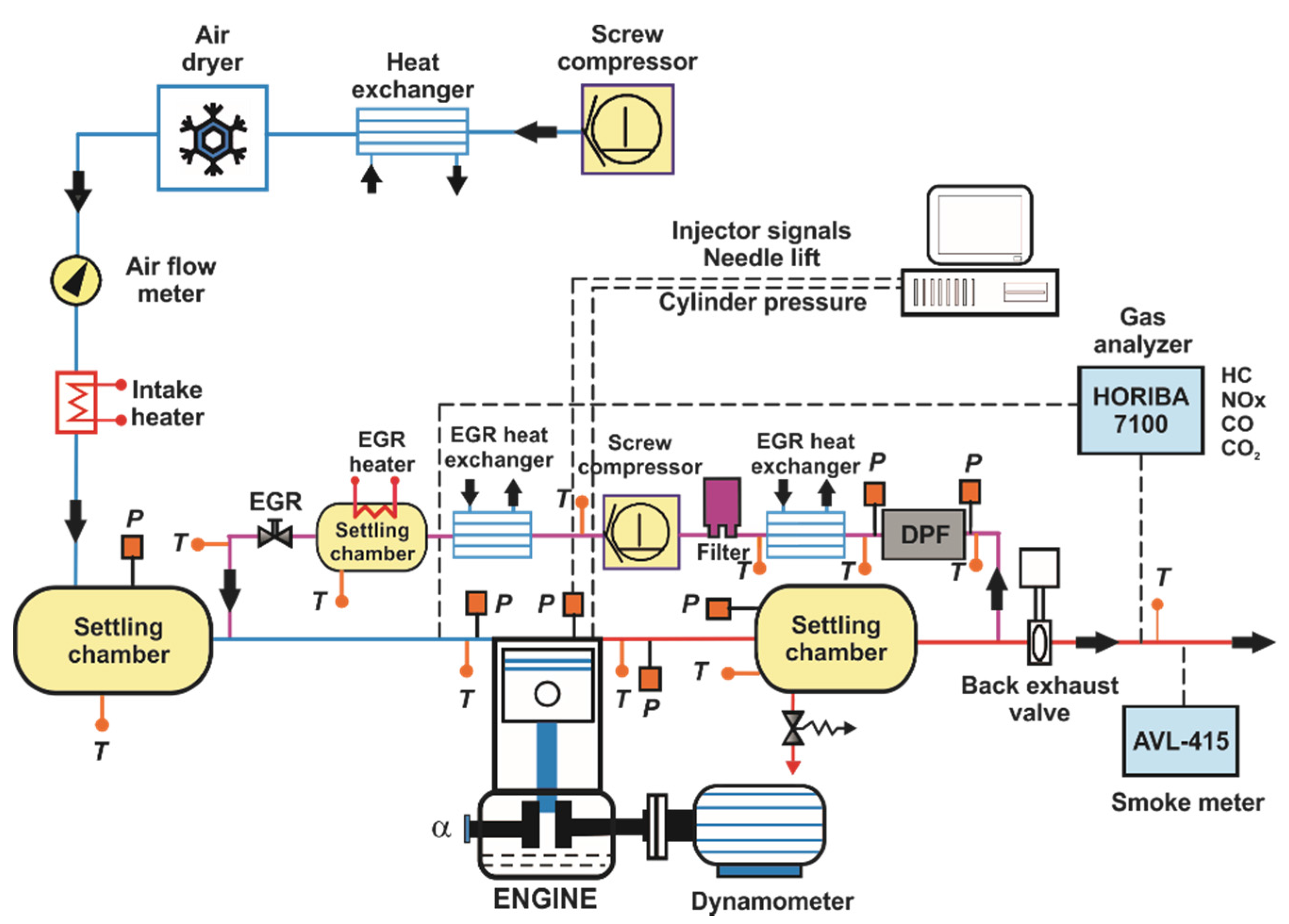
The engine was installed in a fully instrumented test cell, with all the auxiliary facilities required for its operation and control, as it is illustrated in
Figure 1.
To achieve stable intake air conditions, a screw compressor supplied the required boost pressure before passing through an air dryer. The air pressure was adjusted within the intake settling chamber, while the intake temperature was controlled in the intake manifold after mixing with the exhaust gas recirculation (EGR) flow. The exhaust backpressure produced by the turbine in the real engine was replicated by means of a valve placed in the exhaust system, controlling the pressure in the exhaust settling chamber. Low pressure EGR was produced taking exhaust gases from the exhaust settling chamber. The EGR rate was calculated using the experimental measurement of intake and exhaust carbon dioxide (CO2) concentration.
The concentrations of NOx, CO, unburned HC, intake, and exhaust CO2, and oxygen (O2) were analyzed with a five gas Horiba MEXA-7100 DEGR analyzer bench by averaging 40 seconds after attaining steady state operation. Smoke emissions were measured with an AVL 415S Smoke Meter and averaged between three samples of a 1 liter volume each with paper-saving mode off, providing results directly in FSN (Filter Smoke Number) units. Soot measurements of FSN were transformed into specific emissions (g/kWh) by means of the factory AVL calibration.
2.2. In-Cylinder Pressure Signal Analysis
The combustion analysis was performed with an in-house developed one-zone model named CALMEC. This combustion diagnosis tool uses the in-cylinder pressure signal and the mean variables recorded during the experiments (engine speed, coolant, oil, inlet and exhaust temperatures, air, EGR, and fuel mass flow) as its main inputs. The full description of the model can be found in [
29], and the main hypotheses are enumerated next:
The pressure is supposed homogeneous in the combustion chamber. This hypothesis is generally accepted since the fluid and the flame propagation velocity are lower than the speed of sound.
The fluid that evolves inside the combustion chamber is considered as a mixture of air, gaseous fuel, and burned products, which are considered to evaluate the thermodynamic conditions of the mass trapped in the cylinder.
An ideal gas behavior is assumed for the mixture that evolves in the combustion chamber. It is reasonable to accept this assumption for the air and burned products, however, it could seem inadequate for the gaseous fuel. In this sense, Lapuerta [
30] compared the results from the combustion analysis model using different state equations for the gaseous fuel. The results confirmed that the differences in the mean temperature and Rate of Heat Release (RoHR) are small enough to accept the hypothesis.
During the experiments, the in-cylinder pressure was measured with a resolution of 0.2 CAD using a Kistler 61215C pressure transducer coupled with a Kistler 5011B10 charge amplifier. The pressure traces from 150 consecutive engine cycles were recorded in order to compensate the cycle-to-cycle variation during engine operation. Then, the individual pressure data of each engine cycle was smoothed using a Fourier series low-pass filter. Once filtered, the collected cycles were ensemble averaged to yield a representative cylinder pressure trace, which was used to perform the analysis. The first law of thermodynamics was applied between intake valve closing (IVC) and exhaust valve opening (EVO), considering the combustion chamber as an open system because of the blow-by and fuel injection.
The main result of the model used in this work was the Rate of Heat Release (RoHR), which is calculated as stated in Equation (1).
The different terms found in the equation are explained below:
RoHR: This term corresponds to the thermal energy released by the fuel assuming a constant heat power along the combustion event.
mcyl·∆
ucyl: This is the sensible internal energy variation of the gas trapped in the control volume. As detailed in Lapuerta [
31], this term is calculated by means of a specific correlation for each specie. For each temporal step, these correlations are solved as a function of the mean temperature in the control volume while pondering by the mass fraction of each specie.
∆
Qw: This terms accounts the heat transfer from the gas trapped in the control volume to the surrounding surfaces of the piston, liner, cylinder-head and valves. The model do not consider the possibility of fuel impinged in the wall. The instantaneous heat transfer coefficient between the gas and the different surfaces is based on Woschni [
32] with some improvements detailed in Payri et al. [
33]. For the calculation of the different wall temperatures, a nodal heat transfer model was implemented [
34].
p·∆V: This term represents the total work made by the gas trapped in the control volume during the calculation period. For the instantaneous calculation of the combustion chamber volume, a mechanical deformations model is considered. This submodel takes into account both the pressure made by the gas on the piston head and the inertial forces generated by the alternative movement of the masses.
: This term includes all the energetic considerations associated to the fuel injection process, i.e., the flow work, the heat needed to reach the evaporation temperature, and the heating-up of the vapor fuel until reaching the combustion chamber temperature.
Rcyl·Tcyl·∆mbb: Finally, the energy lost due to the blow-by through the piston rings is also considered. The blow-by mass is calculated using an isentropic nozzle model to simulate the gas evolution from the combustion chamber to the oil sump.
Once the RoHR is obtained, the start of combustion (SOC) is defined as the crank angle position in which the cumulated heat release reached a value of 5% (CA5) and the combustion phasing is defined as the crank angle position of 50% fuel mass fraction burned (CA50). Combustion duration was calculated as the difference between CA90 and SOC.
The ideal gas equation of state was used to calculate the mean gas temperature in the chamber. In addition, the in-cylinder pressure signal allowed obtaining the gas thermodynamic conditions in the chamber to feed the convective and radiative heat transfer models, as well as the filling and emptying model that provided the fluid-dynamic conditions in the ports, and the heat transfer flows in these elements. The convective and radiative models are linked to a lumped conductance model to calculate the wall temperatures [
35].
2.3. Results Processing
A merit function [
36] was used to select the best operating conditions in each one of the different studies. The merit function (MF) is defined as shown in Equation (2):
where
xi is the value of the
ith constrained parameter at the given conditions,
xi* is the constraint of the
ith parameter and
i is the index over all the constraints.
The values of the constraints used to calculate the merit function were NOx = 0.4 g/kWh, soot = 0.01 g/kWh, and maximum pressure rise rate (PRR) of 15 bar/CAD. These limitations were aimed to fulfill ultra-low emissions while preserving the engine mechanical integrity. Thus, the contribution to the merit function from a given variable will be zero if only the measured value is less than or equal to the specified limit. When the merit function is non-zero, the contribution from each constrained parameter can be examined separately to quantify the severity of its non-compliance.
If various operating conditions fulfilled all the constraints for the same specific study (which results in a merit function value of zero), the best condition among these was considered the one that minimized the fuel consumption.
3. Paths for Increasing RCCI Efficiency
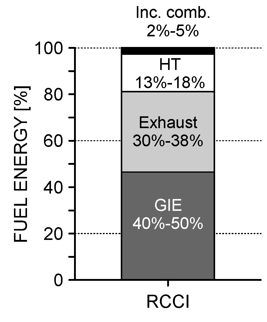
During RCCI combustion, the fuel energy is typically apportioned in the ranges shown in
Figure 2, where the exact values obtained depend on the specific operating conditions and engine characteristics. The present work investigates the effectiveness of different ways to modify the energy outgoing flow path for minimizing the energy losses, thus providing the guidelines to maximize the efficiency of this combustion concept. The different paths are studied in a progressive way, so that the best solution coming from a previous path was maintained for the following steps.
The first path studied to increase the RCCI efficiency is the reduction of the losses associated to incomplete combustion. As seen in
Figure 2, this source of energy loss is not very relevant if compared to the others, as it only represents the 5% of the input energy in the worst case. However, the incomplete combustion results in very high levels of HC and CO emissions, which can compromise the effectiveness of the aftertreatment systems and other subsystems. As the literature demonstrates, higher combustion losses occur at low loads, where lower in-cylinder pressure and temperature occur [
22]. The solution explored in this work to minimize combustion losses is the optimization of the engine settings, because it is the most straightforward solution to manage the in-cylinder reactivity.
The second way proposed for increasing the gross indicated efficiency is the reduction of the heat transfer losses. In this sense, it is expected that only a portion of the recovered energy will be extracted as additional gross work, while the rest will be merely rejected as thermal exhaust loss due to the higher exhaust temperature. In any case, rising the exhaust temperature is more desirable than rejecting the heat to the coolant, because it contributes to increasing the conversion efficiency of the aftertreatment systems.
The third path to maximize RCCI efficiency relies on the fuel properties modification to look for a proper in-cylinder fuel reactivity that enhances the combustion propagation. In this sense, several studies confirm that, in order to achieve high efficiency while reducing NOx and soot emissions, the higher portion of the energy should come from the low reactivity fuel [
22,
26]. This fact suggests that the low reactivity fuel characteristics and its amount in the blend must have a key role on the in-cylinder reactivity, so this will be the fuel source varied during the investigation.
3.1. Engine Settings Combination
The first path for increasing the RCCI efficiency relies on the engine settings combination. To do this, it was decided to control three variables that govern the in-cylinder reactivity. Two of them were the EGR rate and intake gas temperature (T), which define the gas charge thermodynamic properties. The third variable studied was the gasoline fraction (GF), defined as the mass ratio of gasoline versus the total fuel injected, because it defines the in-cylinder fuel reactivity.
The tests were done at 1200 rpm and 7.5 bar IMEP, which corresponds to 25% load in this engine platform. This load was selected as representative as it is the minimum load considered in the World Harmonized Stationary Cycle (WHSC), proposed by the EURO VI regulation. The combustion phasing (CA50) was kept constant at +5 CAD ATDC, because this combustion phasing was found to offer a good compromise between engine-out emissions and performance. The injection strategy for diesel fuel was fixed at −60/−50 CAD ATDC, and the pair of values EGR + GF and T + GF were adjusted to keep the combustion phasing at the desired value.
Table 4 summarizes the engine settings tested with both strategies as well as those for the baseline operating condition.
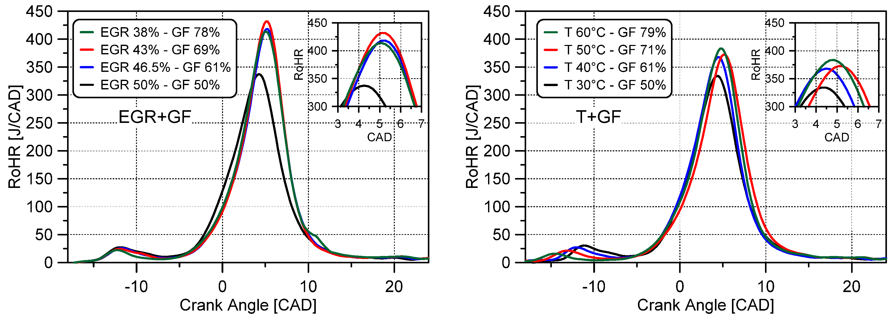
Figure 3 shows the RoHR traces for the two strategies, EGR + GF (left) and T + GF (right). Comparing both graphs, it is confirmed that EGR + GF strategy leads to higher maximum RoHR peaks than T + GF. In the case of EGR + GF, the start of the low temperature heat release (LTHR) and the LTHR peaks are equal for the four conditions tested. By contrast, the tests of T + GF denote a clear dependence of the LTHR onset on the intake temperature, showing earlier onset as temperature rises. In addition, it can be seen that the magnitude of the LTHR increases as diesel fuel mass increases (GF is reduced).
In order to select the best tests for each strategy, the merit function defined in
Section 2.3 was applied to the complete batch of tests.
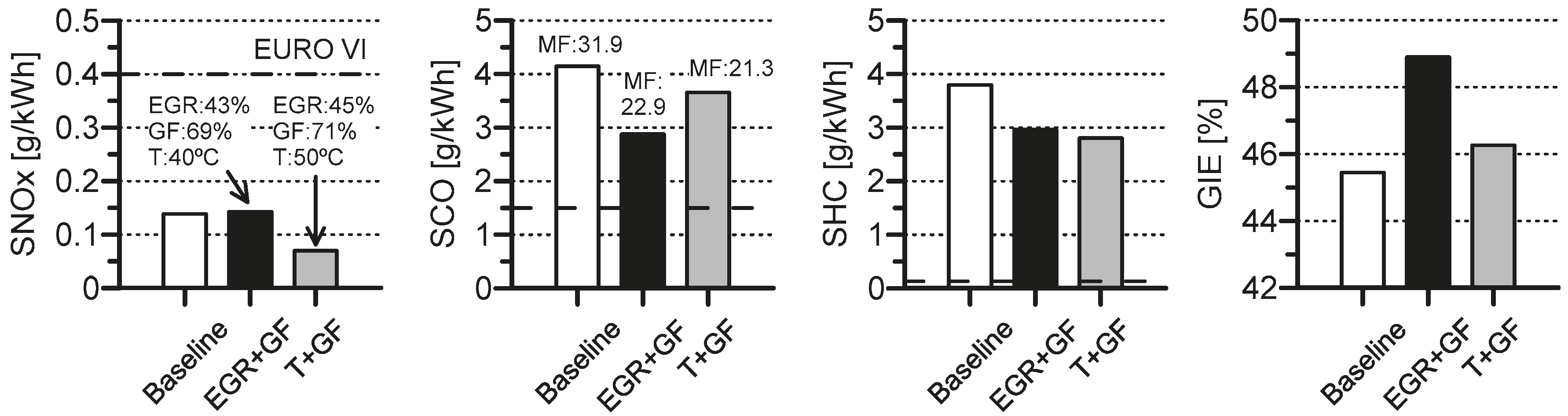
Figure 4 represents the engine-out emissions and efficiency for the best tests of the two strategies as well as for the baseline condition. It is worth noting that the tests selected for both strategies are those that have near 70% of GF (EGR = 43% and T = 50 °C). The results show that both methods allow the decrease of unburned products and improve the GIE without penalizing NOx and soot emissions as compared to the baseline condition. Note that soot emissions are not depicted in the graph because all the tests provided soot levels under the detection limit of the smoke meter. Moreover, it is clear that EGR+GF provides higher gross indicated efficiency (GIE) than the T + GF strategy.
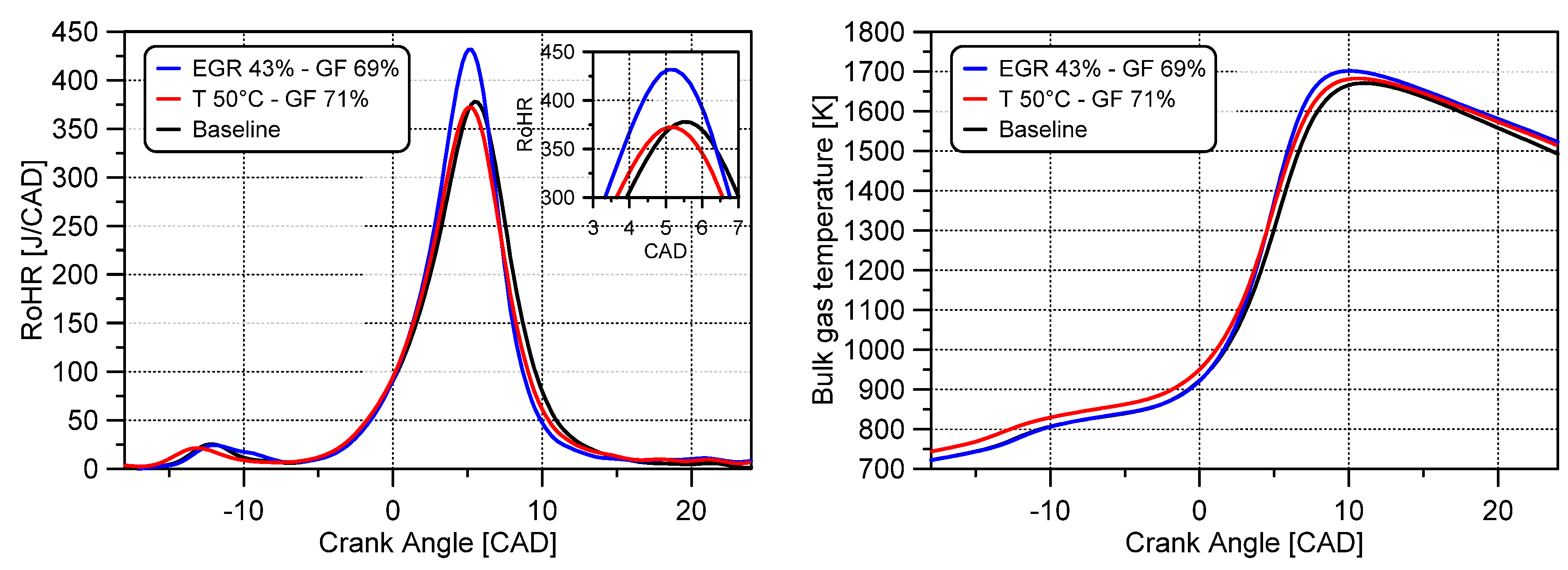
The results of
Figure 4 can be explained looking at
Figure 5, where the RoHR traces and bulk gas temperature for the three cases are represented. As seen from
Figure 5, the RoHR profiles of baseline and T + GF conditions are very similar, with only slightly earlier LTHR and HTHR onset in the case of T + GF due to the higher intake temperature (+10 °C). The RoHR peak of the EGR + GF strategy is 50 J/CAD greater than the other two cases, which results in higher bulk gas temperature, even using an intake temperature 10 °C lower than T + GF.
The reduction of the unburned products found in
Figure 4 with the two strategies, should be related with the faster expansion period as compared to the baseline case. On the other hand, CO emissions are greatly influenced by the in-cylinder temperature. As it can be seen, the bulk gas temperate exceeds 1400 K in all cases, which is the threshold temperature to accelerate the CO oxidation. Since the bulk gas temperature of EGR+GF and T + GF is higher than that of the baseline operating condition, it is expected that a greater part of the in-cylinder charge experiences temperatures greater than 1400 K, explaining the CO reduction observed with the two strategies.
In the light of the results, it is possible to conclude that to achieve low emissions and high efficiency under the operating conditions tested, the EGR rate should be in the range of 43%–45%, GF 69%–71%, and intake temperature 40–50 °C. Moreover, the most efficient strategy seems to be achieved with slightly lower GF and higher oxygen concentration than the others. This knowledge will be used to define the boundary conditions in the next studies.
3.2. Piston Bowl Geometry Optimization
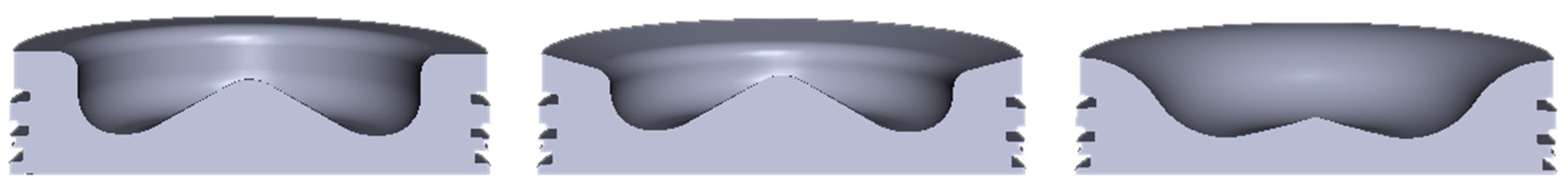
As a second path to increase RCCI efficiency, it was considered to modify the piston geometry for reducing the in-cylinder heat transfer losses. For this purpose, two new piston bowl geometries were defined. The volumes of the designed combustion bowl geometries were matched to keep the same geometric compression ratio as with the stock piston, which is 14.4:1. The three geometries are illustrated in the cross-sectional views presented in
Figure 6.
The first new piston was called ‘tapered’. This bowl shape maintains the same central geometry than the stock piston, with slightly higher height necessary to keep the same compression ratio. The major change versus the stock piston is the tapered shape of the piston crown, which has two main purposes. The first one is to limit the heat transfer in this region through the heat transfer coefficient reduction due to the lower squish flow velocities [
37]. Second, the tapered shape is intended to improve the penetration of high temperature gas into the squish and near-liner regions, where a great amount of gasoline gets trapped [
22]. Moreover, this geometry resulted in near 6% less piston surface area than the stock piston which also contributes to the heat transfer reduction.
The second geometry was called ‘bathtub’ as it follows some of the design guidelines provided by Splitter et al. [
38,
39], which suggested that the efficiency of RCCI improves as the piston bowl radius increases and the bowl depth decreases. The application of these findings to the piston blanks, resulted in a piston bowl geometry with near 16% less piston surface area than the stock piston. This large reduction in surface area, in combination with the more quiescent combustion chamber created by the resulting flatter bowl geometry, should significantly reduce the heat transfer losses.
To evaluate the influence of the piston bowl geometry on RCCI combustion, a batch of parametric studies of the key variables governing the fuel reactivity stratification (diesel injection timing and GF) were performed from low to high load at 1200 rpm.
Table 5 summarizes all the engine settings tested. Note that the effective compression ratio (CR
eff) was reduced down to 11:1 in the case of 18 bar IMEP to avoid the excessive knocking levels provoked by the sudden ignition of the high amount of homogeneously mixed gasoline. The CR reduction was done by shortening the intake event duration (early Miller cycle), through the VVA system.
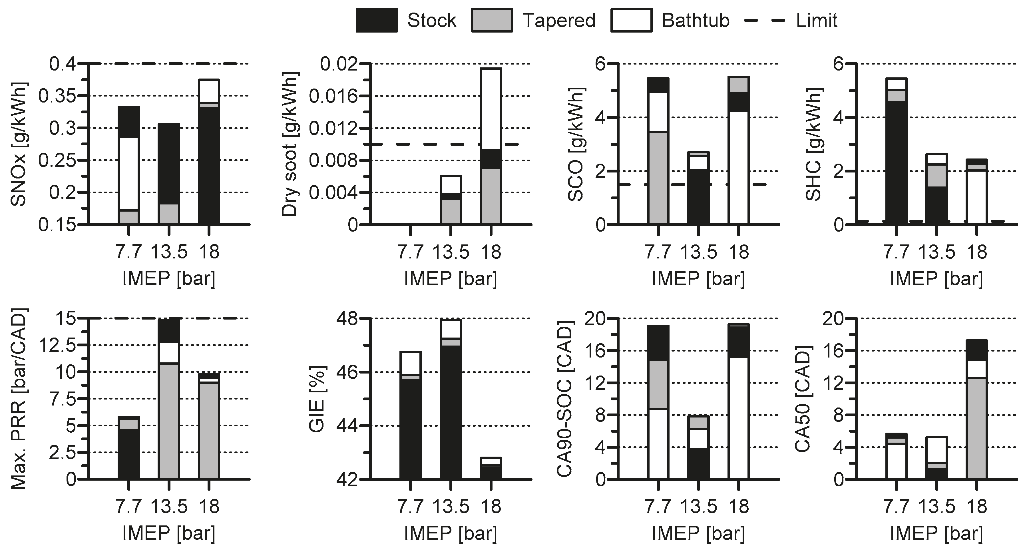
The bar chart shown in
Figure 7, in which all bars have the same baseline value, summarizes the best merit function results for each piston and load. The tests at 7.7 and 13.5 bar correspond to double injection, while single injection was found to be more suitable at 18 bar. As it can be seen EURO VI NOx emissions levels are reached with all the pistons. However, only the stock and tapered geometries allow working in the region under 0.01 g/kWh of soot emissions. From the second subfigure, it can be inferred that the bathtub piston has a higher sooting tendency than the other two geometries. This is thought to be related to the less prominent bowl, with reduces the turbulence near the top dead center (TDC) and worsens the air-fuel mixing process. This hypothesis is in line with the results, since the sooting tendency is more evident at high loads, where near TDC single injections are used and therefore the bowl shape plays a key role on the mixing process. In terms of CO and HC emissions, all the pistons are far from EURO VI levels. As it can be seen, the stock piston leads to less unburned products than the new geometries at low and medium loads. The inversion of this trend at high load is thought to be related with the change from double to single injection strategy. In this sense, the more prominent bowl of the stock piston confines the diesel injection and avoids increasing the reactivity in the crevice zone, which worsens the burning of the gasoline trapped in this region.
Maximum PRR is reduced with the two new geometries, providing a great margin to the limit at medium load conditions. The combustion duration (CA90-SOC) decreases when moving from 7.7 to 13.5 bar, and later increases. This occurs because the more reactive in-cylinder conditions at 13.5 than 7.7 bar allow introducing greater amount of gasoline, which becomes homogeneously-mixed and promotes much faster heat release, even having similar combustion phasing (CA50). At 18 bar IMEP, the injection strategy follows a single pattern to reduce the knocking levels. This leads to some diffusion combustion period, which provokes an increase of both the combustion duration and combustion phasing. Finally, as it can be inferred from the figure, the GIE has an inverse trend with the piston surface area, i.e., higher efficiency as bowl surface area reduced. This fact suggests that heat transfer reduction is contributing to the efficiency gain with the two new geometries. However, considering the excessive sooting tendency of the bathtub piston at high load and that the tapered piston does not provide a notable GIE increase versus the stock geometry, it was decided to keep the stock piston mounted in the engine for the next studies.
3.3. Fuel Autoignition Qualities Modification
The third path to maximize RCCI efficiency is based on modifying the fuel properties in order to look for a suitable combination of high reactivity fuel (HRF) and low reactivity fuel (LRF) that improves RCCI combustion.
Considering the mandatory presence of biofuels in the future context of road transport [
40], the ability of ethanol to be blended with gasoline [
41], and the main conclusions extracted from RCCI literature regarding ethanol [
42], the low reactivity fuels selected to perform this study are E10-95, E10-98, and E20-95. In addition, a diesel fuel containing the maximum biodiesel percentage currently allowed to be distributed as a regular fuel grade in Europe, 7% by volume, has been used as high reactivity fuel during all the study. This will be referred to as diesel B7. The main characteristics of the four fuels are listed in
Table 6. All the properties were obtained following the American Society for Testing and Materials (ASTM) standards.
As can be seen in
Table 7, the lower heating value (LHV) of E20-95 is lower than the other two LRF. This is because of the greater ethanol content in the blend. To take into account this fact during the comparison, the premixed energy ratio (PER) is presented in Equation (3). The PER is defined as the energy ratio of the LRF versus the total delivered energy, so that it ensures that during the tests all the LRF are compared at equal conditions in terms of energy delivered to the engine.
As done in the previous section, to evaluate the influence of the LRF properties on RCCI combustion, a batch of parametric studies varying the diesel injection timing and PER were proposed at low, medium, and high loads at 1200 rpm. The different settings studied are depicted in
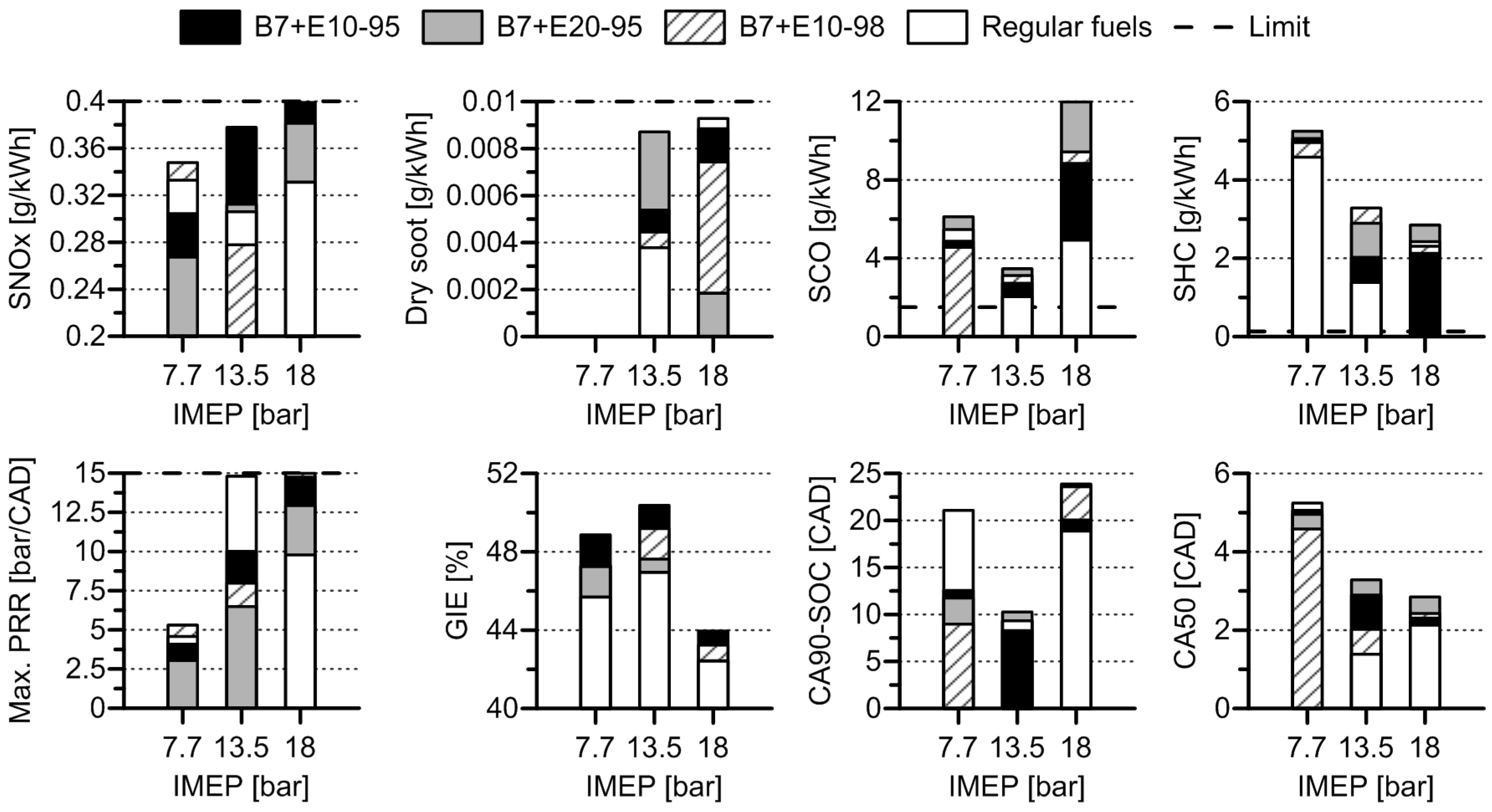
Table 7.
Figure 8 synthetizes the results of the best tests extracted from the merit function. As it can be seen, all the fuels allow operating under the NOx and soot emissions limits. It is interesting to remark that, at 7.7 bar gross IMEP, soot emissions were under the detection limit of the smoke meter for all the fuels. This is due to the high PER used (low diesel amount injected) and the large advance of the diesel injection timing [
43], which provides enough mixing time to avoid soot formation [
44]. Focusing on CO and HC emissions, it is possible to state that, as a general trend, the operation with biofuels results in higher levels of unburned products than with regular diesel and gasoline fuels. Moreover, it is seen that the higher levels of both emissions are produced with E20-95 fuel, which has a large ethanol content. Considering this, the higher CO and HC levels are thought to be related with the greater enthalpy of vaporization of ethanol, which results in a cooling effect in the intake manifold and therefore lower temperature peak at TDC.
The maximum PRR increases as load increases. In this case, even using a single injection pattern at 18 bar, values near the 15 bar/CAD limit are observed. This is because the combustion phasing (CA50) has been reduced substantially as compared to the results shown in the previous section. On the other hand, following the same reasoning as the previous section, the combustion duration (CA90-CA10) reduces first, and later increases. Regarding engine performance, the figure shows that all the biofuels investigated allow more efficient operation than regular fuels (note that the GIE values for E20-95 and E10-98 at low load are equal). In addition, it is clear that B7 + E10-95 performs better than the rest of the fuels in all the load range, promoting the highest increase of GIE at low load (3% higher GIE than regular fuels).


