1. Introduction
Wire ropes are one of the most common structural members used for transmitting tensile forces. With high flexibility and considerable strength, wire ropes are in widespread use, especially in marine environments. Whether for handling cargo, mooring, or rigging, wire ropes can be found at shipyards, ports, ships, and offshore facilities. Considering the high loads they must maintain, and the harsh environmental and operational conditions coupled with pre-existing defects and/or imperfections in manufacturing that can serve as crack initiation points under fatigue loading conditions, it is easy to understand the need for the proper characterization of stress distribution and the remaining life of wire ropes. If not properly analyzed and designed, the collapse of wire ropes could have disastrous consequences [
1,
2,
3].
There has been a considerable amount of effort in describing the behavior of ropes and strands. Most analytical solutions generally exclude frictional and contact effects [
4] and they are based on equilibrium equations related to the boundary conditions of actual problems. If trying to consider friction and contact, plus some other operational conditions, numerical techniques such as finite element (FE) analysis are usually employed.
Some of the previous work on numerical simulations of ropes and strands include FE analysis of simple straight strands [
5] or the development of a model for predicting the mechanical response of an independent wire rope core [
6]. More recent research concentrates on the FE modeling of wire ropes (cables) with the inclusion of fatigue effects that take into account multiscale effects [
7], the FE modeling of multi-strand wire ropes exposed to axial and torsion loads [
8], or a combination of experimental analysis and finite element modeling to understand the behavior of a rope [
9]. Furthermore, input parameters for numerical analysis can be introduced from experimental investigations of wire ropes, such as sea trials for ropes in marine applications [
10].
However, none of the reviewed references take into consideration the reduction of wire rope cross-section diameters caused by damage or the effect on the remaining service life. One of the advantages of wire ropes is the possibility of continued operation, even if some of the strands are broken, i.e., the rope diameter is reduced. This paper uses FE analysis to perform stress and fatigue analysis of different design types of wire ropes. The size of the wire rope cross section is varied in order to simulate progressive damage to wires, and the remaining service life is numerically predicted. The aim is to provide a better understanding of the mechanical behavior of the damaged wire ropes under various conditions and hence to be able to choose an appropriate wire rope design from engineering and economic points of view.
2. Preliminary Consideration
The wires in straight wire ropes under tensile load are mainly strained by tensile stresses [
11]. In most practical cases, nominal rope tensile stress is merely a division of the rope tensile force and the wire rope cross section. However, the real tensile stress in individual wires can vary from this nominal value mainly according to the different lay angles of the wire and the strand layers. Real tensile stresses can then be calculated according to [
12]:
where index
i stands for the individual wire and
k for the layers;
E is the modulus of elasticity,
A is the cross-sectional area of the wire,
υ is Poisson’s ratio, α is the lay angle,
n is the number of wire layers,
z is the number of wires in the layer, and
S is the tensile force.
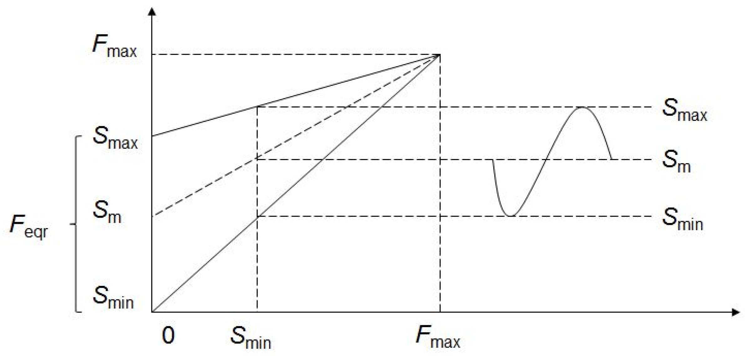
The fatigue process generally involves the formation of a crack initiation point at preexisting flaws and crack propagation under the influence of a variable load. Besides variable tension load, factors such as fretting, friction, wear, or corrosion also influence the speed of the fatigue process. The fracture of strands in the wire rope is gradual; the rope maintains functionality even if some of the strands are broken. Mechanisms that affect load variation in wire ropes can be tension fatigue, bending-over-sheaves, free bending, and torsion fatigue.
Tension fatigue, the most common mechanism of wire rope fatigue, involves changes in axial tensile load that affect the stress distribution in ropes. It primarily occurs in fixed wire ropes, lifting, and hoisting applications. Change in mass and acceleration is the primary source of axial load variation. Given that a dominant parameter for this type of fatigue is load range, the number of load cycles for tension fatigue can be estimated using a simple power law equation [
12]:
where
c stands for an experimentally obtained constant,
m is an empirically determined power number, and
Feqr is the equivalent load range:
with
Smax,
Smin, and
Sm being the maximum, minimum, and mean load, and
Fmax the ultimate breaking load (
Figure 1).
3. Finite Element Analysis
3.1. Geometry
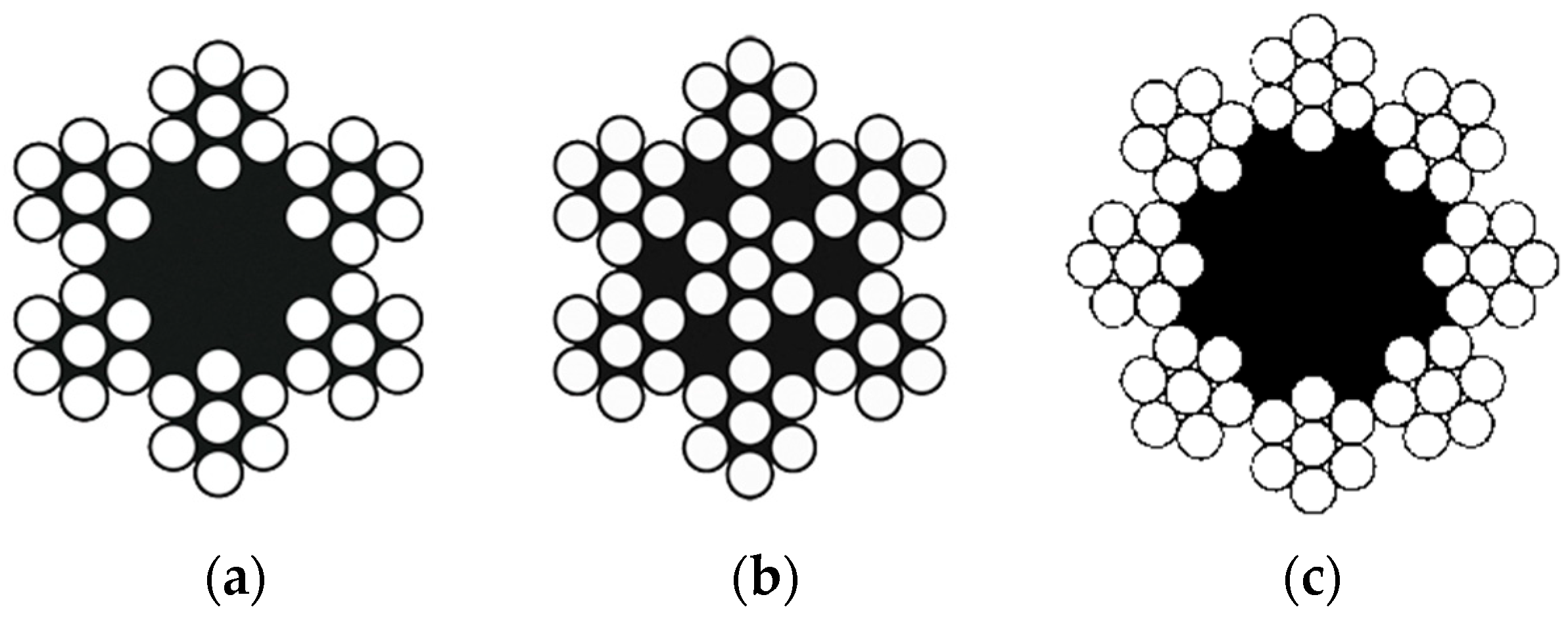
Three types of wire ropes are considered here [
13,
14]. The first is the 6 × 7 fiber core wire rope (
Figure 2a). This rope is used when resistance to wear and abrasion are important factors. The cross-section surfaces of wires are large, and ropes can become quite rigid in larger diameters, but can stand a great deal of wear. It shows some weakness in withstanding bending stresses compared to ropes with smaller cross-section wire surfaces. In marine applications, they are usually used in standing rigging, with cranes, and in ship towing.
The second type of wire rope considered is the 6 × 7 wire strand core wire rope (
Figure 2b), which is commonly referred to as the 7 × 7 wire rope. This rope can become quite rigid in diameter, larger than 5 mm when they are used in static applications. In the marine industry, they are usually used in a standing rigging and general marine engineering applications. A wire rope with an 8 × 7 fiber core is also considered (
Figure 2c). Somewhat similar to the 6 × 7 wire rope, it offers improved fatigue resistance and flexibility in larger diameters.
3.2. Material Properties
Material properties of wire rope material are taken as modulus of elasticity E = 180 GPa, Poisson’s ratio ν = 0.3, yield strength RYS = 1.54 GPa, and ultimate tensile strength RTS = 1.8 GPa.
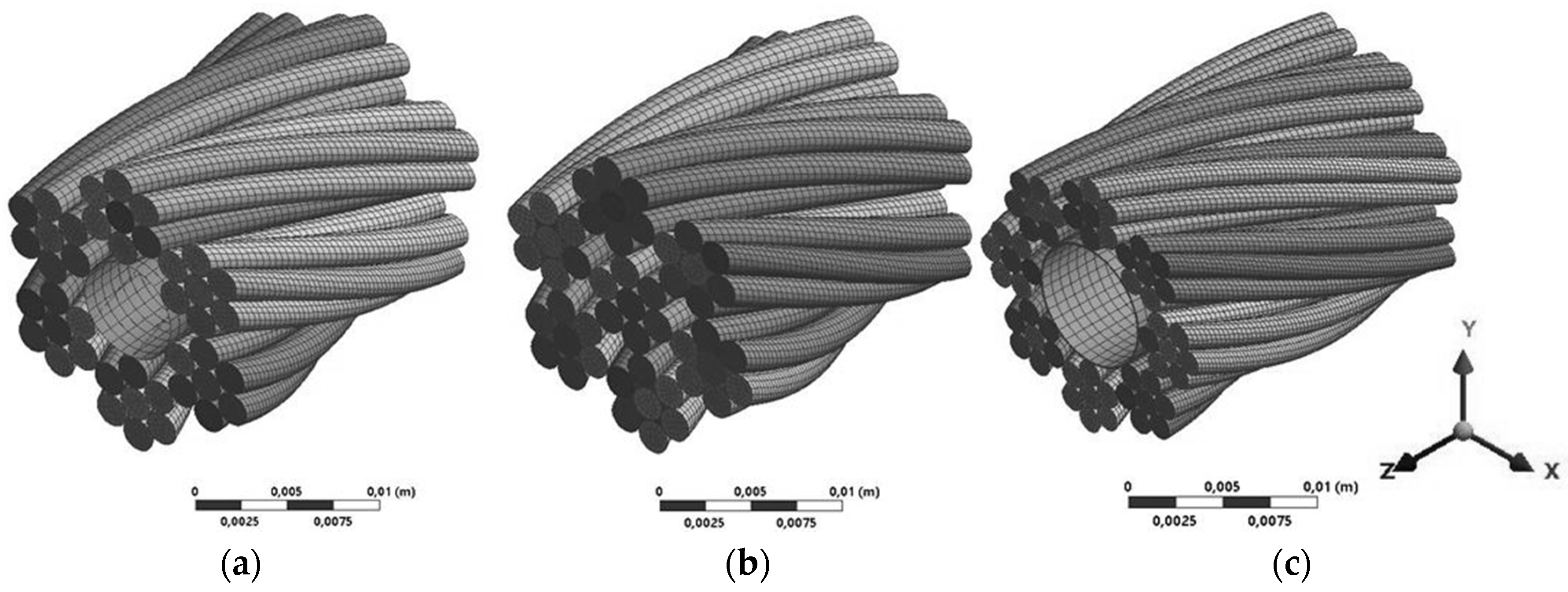
3.3. Finite Element Model
Parametric solid models of wire rope were built using SpaceClaim Direct software, while the rest of the parameters of FE modeling were performed in ANSYS Workbench. Only a 20 mm long segment of the rope was modeled in order to reduce computational time (
Figure 3). The model was discretized with 20-node brick solid elements. Frictionless contact between wires was defined because, for axially loaded rope, relative displacements between wires are negligible; consequently, friction does not add significantly to the stress strain evolution and can therefore be neglected in order to keep the model simple and effective [
4,
15]. Workbench allowed for a frictionless contact condition with no separation to be defined where little relative motion between the surfaces is allowed. Although the broken wire can, due to friction effects, resume its load once a certain distance from the rupture point is reached, the frictionless approach is employed here to account for the worst case scenario, where the rupture point is at a critical position for the load bearing ability of the wire.
As for the boundary conditions, one end of the rope was fixed. On the other end, axial force was applied and circumferential displacements were constrained in order to prevent the rotation of the strands along the longitudinal axis, an approach proved to be valid by previous research [
16]. A total force of 147 kN was applied, evenly distributed between the wires. The inner fiber cores of the 6 × 7 and 8 × 7 wire ropes were modeled as a surface that does not contribute to carrying the axial load and acts only as radial support for the strands. According to [
16], perturbation due to boundary constraints are negligible for the FE model, which has a length equal to at least 1/16 of the helical pitch.
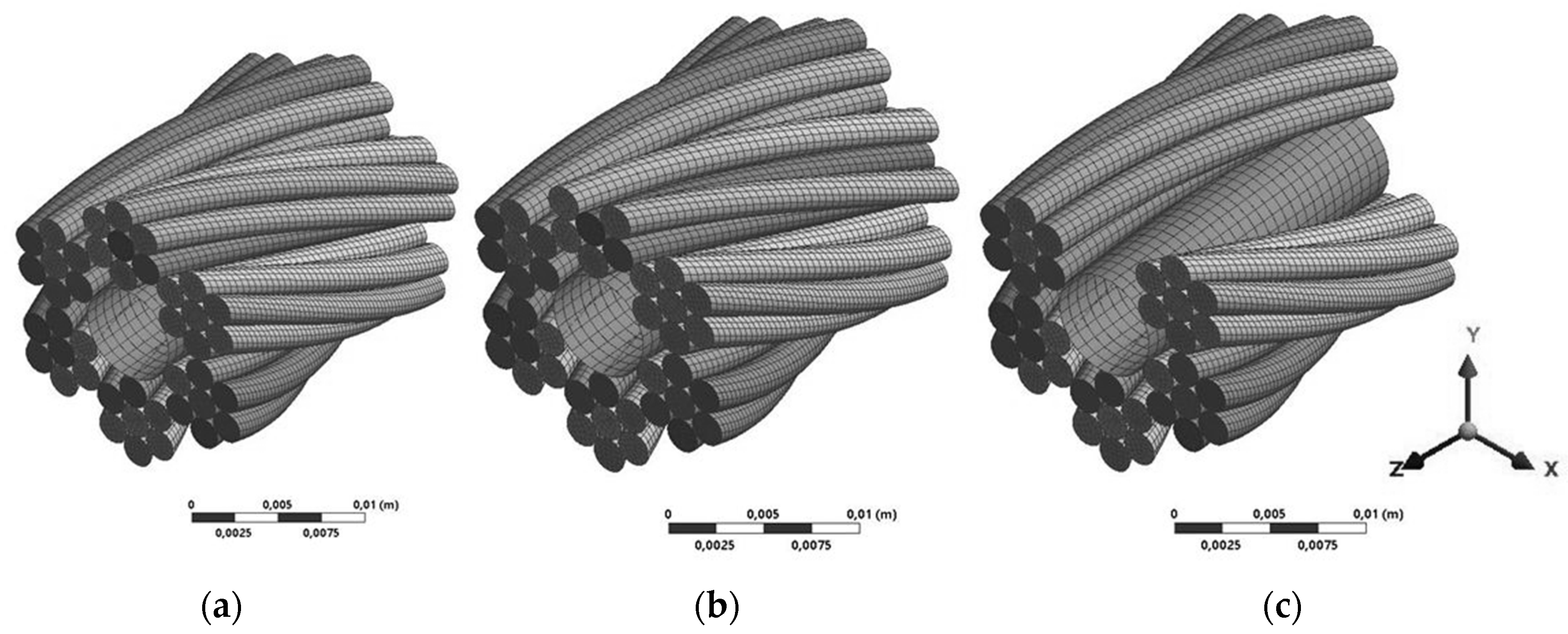
Damage to the wire rope was modeled simply by suppressing individual wires or entire wire strands under the presumption that, once a wire is damaged, it can no longer carry the load and thus be neglected in the FE model.
Figure 4 shows the 6 × 7 wire with full cross-section area, where one wire and one strand are suppressed.
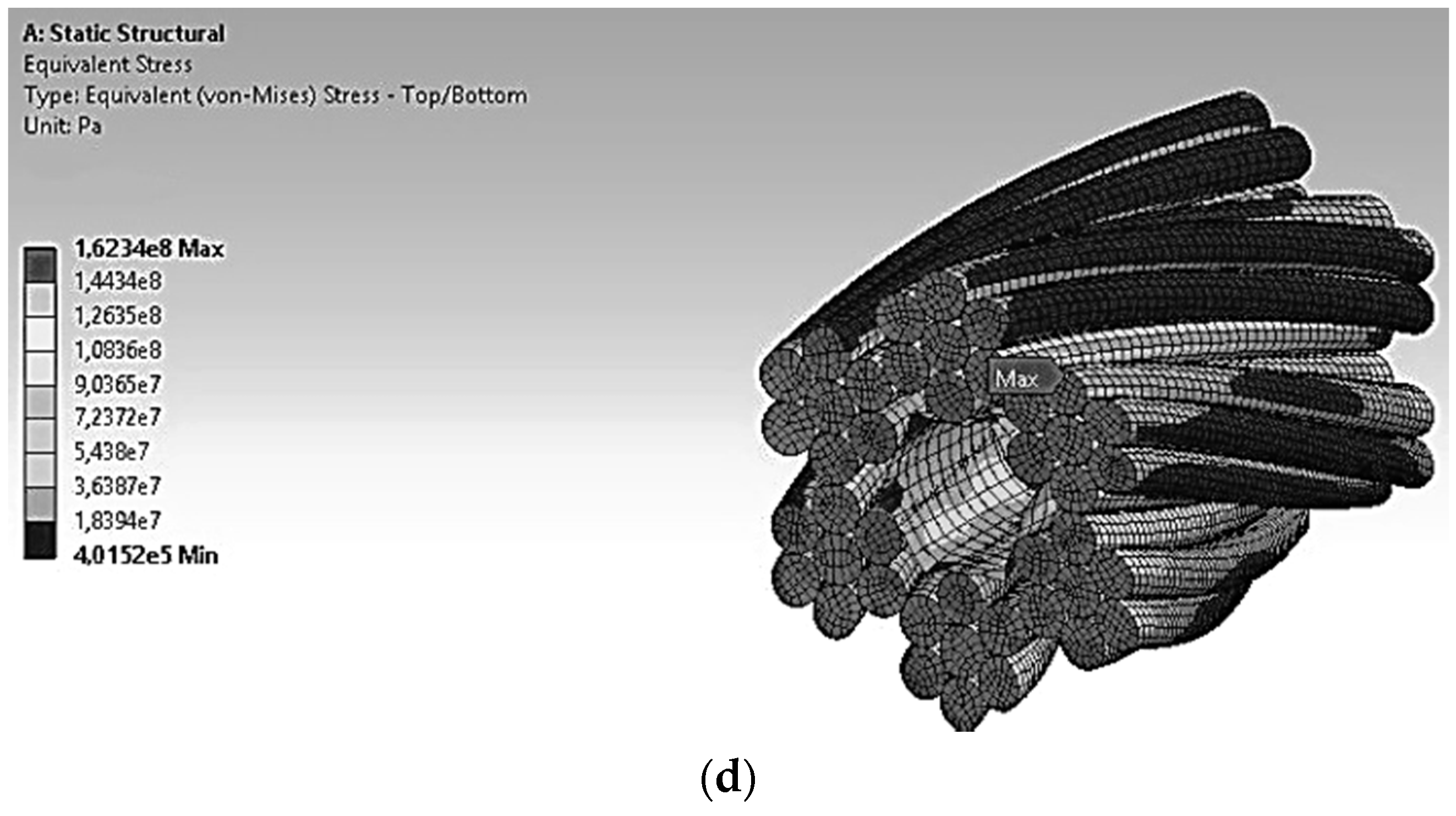
4. Results and Discussion
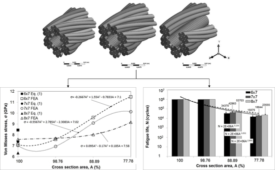
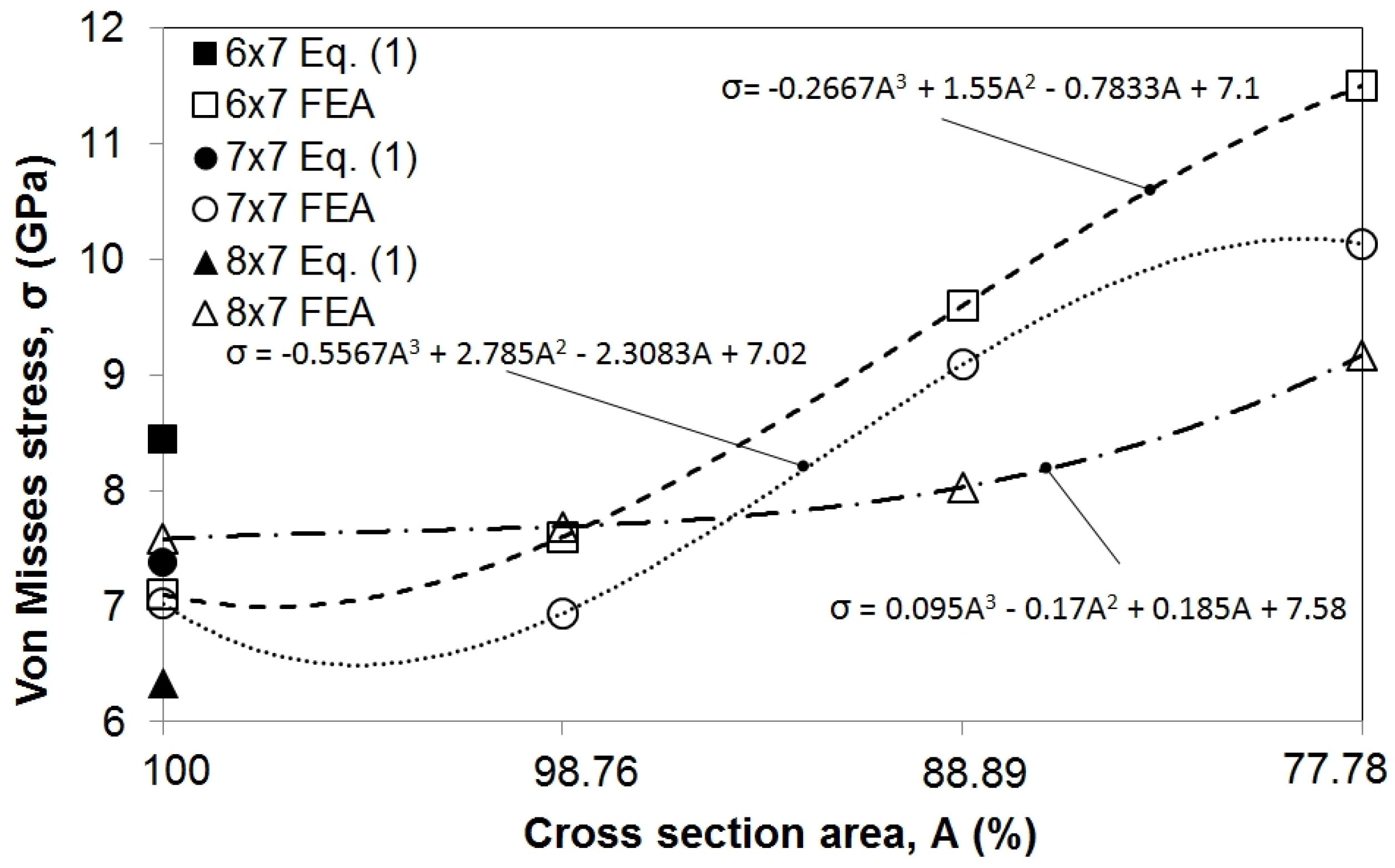
Using FE analysis, maximum Von Mises stresses are calculated for the 6 × 7, 7 × 7 and 8 × 7 wire ropes. This was done for wire ropes with a full cross-section area and a reduced cross-section area (98.76%, 88.89%, and 77.78% of the full area, which roughly corresponds to a one-wire, one-strand, or two-strand reduction in the rope diameter). Change in Von Mises stresses according to the reduction in cross-section area can be seen in
Figure 5.
To verify numerically obtained stress levels, stress was also calculated analytically for wire ropes with full cross-section areas according to Equation (1). Good correspondence of analytically and numerically obtained stresses for the 7 × 7 configuration provided confidence in further use of FE analysis in calculating the stress of wire ropes with a reduced cross-section area. As for the 6 × 7 and 8 × 7 configurations, values are a bit more dissipated, which can be accounted for different types of core (
Table 1), and this issue requires further investigation in future research. It can clearly be seen that a small reduction in cross-section area (to 98.76% of the initial area) does not cause a significant elevation in stress level; however, with further reduction (88.89% and 77.78% of the initial area), stress levels rise steeply.
Using the obtained results and linear regression, the relationship between the reduction in the cross-section area and Von Misses stress levels is established through three equations that are quoted in
Figure 5.
Using FE stress analysis results and a modified Goodman diagram [
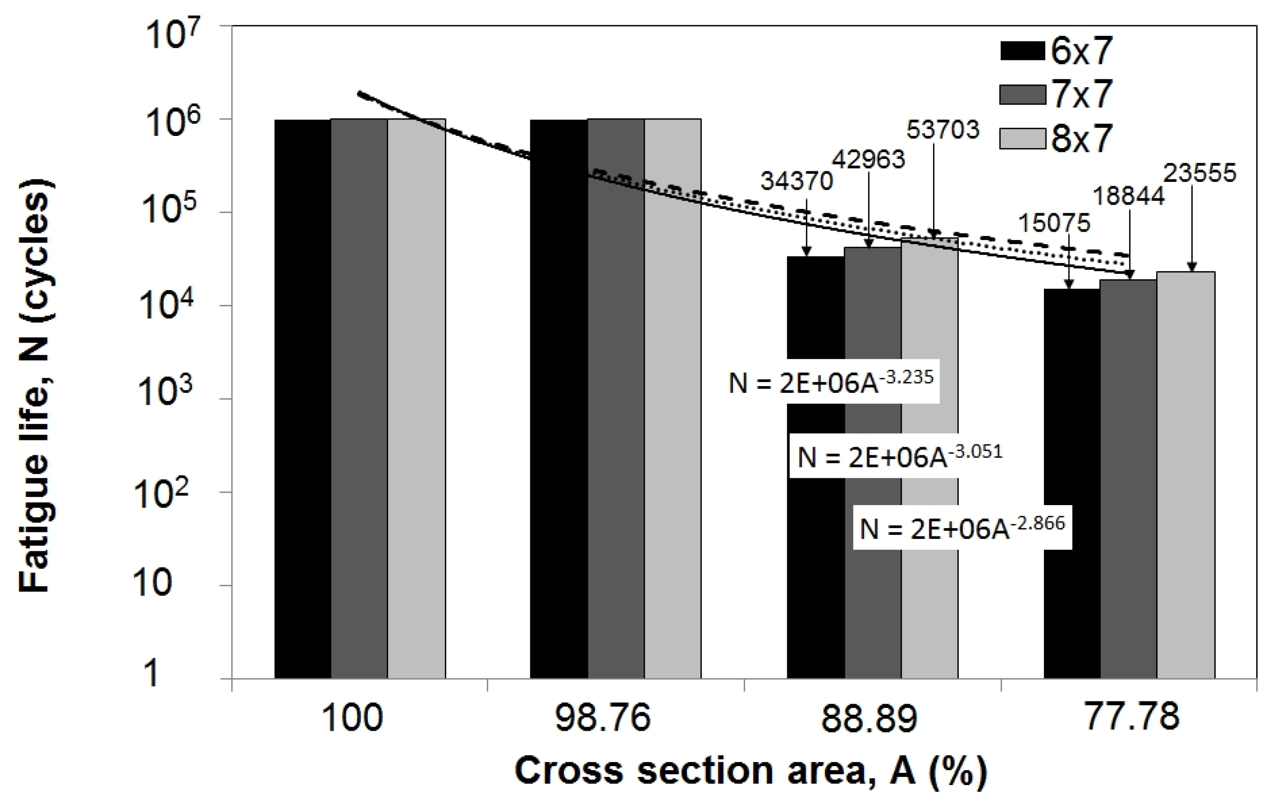
4], the remaining fatigue life was predicted. A constant amplitude and zero-based load was employed since wire ropes can only withstand tensile load. Results (
Figure 6) show that there is virtually no change in remaining life when the damage causes a reduction in cross-section area to 98.76% of the initial area. However, with further reduction (88.89% and 77.78% of the initial area), remaining life decreases significantly to about 3% and 1.5% of the remaining life of the wire rope with a full diameter.
Furthermore, when comparing the remaining life of the 6 × 7, 7 × 7, and 8 × 7 wire ropes with reduced cross-section areas, it can be noticed that the 8 × 7 wire rope offers a duration that is about 50% longer when compared to the 6 × 7 wire rope.
Similar to
Figure 5, using the obtained results and linear regression, the relationship between the reduction in cross-section area and fatigue life is established through the three equations in
Figure 6.
5. Conclusions
Three design types of wire ropes were considered in this paper—6 × 7, 7 × 7, and 8 × 7. The idea was to investigate the effect of cross-section area reduction on stress levels and remaining fatigue life. Von Mises stress was obtained using FE analysis for wire ropes with full cross-section areas and reduced cross-section areas to 98.76%, 88.89% and 77.78% of the initial value. Results show a significant increase in stress levels with reductions in cross-section areas below 90% of the initial area. Furthermore, this reduction also caused significant decreases in the remaining life of the wire ropes. However, it was noticed that the 8 × 7 wire rope had an improved duration compared to the 6 × 7 and 7 × 7 wire ropes, even with a reduced diameter.
The results of this research could be useful in the process of designing transportation systems that rely on the use of wire ropes. In severe operating conditions, such as those of marine, port, or offshore industries, findings regarding the fatigue implications of damaged wire ropes can have a significant impact on economical and safety factors that need to be considered when dealing with choosing, maintaining, and replacing wire ropes.
Acknowledgments
This work has been partly supported by University of Rijeka, Croatia, under the project 13.07.2.2.04 and partly by International Association of Maritime Universities under the project “MarStruFail” that covered the costs to publish in open access.
Author Contributions
Goran Vukelic conceived the idea and designed analysis procedure; Goran Vizentin performed the analysis; Goran Vukelic analyzed the results; Goran Vukelic and Goran Vizentin wrote the paper.
Conflicts of Interest
The authors declare no conflict of interest.
References
- Piskoty, G.; Zgraggen, M.; Weisse, B.; Affolter, C.; Terrasi, G. Structural failures of rope-based systems. Eng. Fail. Anal. 2009, 16, 1929–1939. [Google Scholar] [CrossRef]
- Torkar, M.; Arzensek, B. Failure of crane wire rope. Eng. Fail. Anal. 2002, 9, 227–233. [Google Scholar] [CrossRef]
- Peterka, P.; Kresak, J.; Kropuch, S.; Fedorko, G.; Molnar, V.; Vojtko, M. Failure analysis of hoisting steel wire rope. Eng. Fail. Anal. 2014, 45, 96–105. [Google Scholar] [CrossRef]
- Costello, G.A. Theory of Wire Rope, 2nd ed.; Springer: New York, NY, USA, 1997. [Google Scholar]
- Jiang, W.G.; Henshall, J.L.; Walton, J.M. A concise finite element model for three-layered straight wire rope strand. Int. J. Mech. Sci. 2000, 42, 63–86. [Google Scholar] [CrossRef]
- Elata, D.; Eshkenazy, R.; Weiss, M.P. The mechanical behavior of a wire rope with an independent wire rope core. Int. J. Solids Struct. 2004, 41, 1157–1172. [Google Scholar] [CrossRef]
- Liu, Z.; Guo, T.; Chai, S. Probabilistic fatigue life prediction of bridge cables based on multiscaling and mesoscopic fracture mechanics. Appl. Sci. 2016, 6, 9. [Google Scholar] [CrossRef]
- Xiang, L.; Wang, H.Y.; Chen, Y.; Guan, Y.J.; Wang, Y.L.; Dai, L.H. Modeling of multi-strand wire ropes subjected to axial tension and torsion loads. Int. J. Solids Struct. 2015, 58, 233–246. [Google Scholar] [CrossRef]
- Fontanari, V.; Benedetti, M.; Monelli, B.D. Elasto-plastic behavior of a Warrington-Seale rope: Experimental analysis and finite element modeling. Eng. Struct. 2015, 82, 113–120. [Google Scholar] [CrossRef]
- Gordelier, T.; Parish, D.; Thies, P.R.; Johanning, L. A novel mooring tether for highly-dynamic offshore applications; mitigating peak and fatigue loads via selectable axial stiffness. J. Mar. Sci. Eng. 2015, 3, 1287–1310. [Google Scholar] [CrossRef]
- Chaplin, C.R.; Potts, A.E. Wire Rope Offshore—A Critical Review of Wire Rope Endurance Research Affecting Offshore Applications; Health and Safety Executive: London, UK, 1991.
- Feyrer, K. Wire Ropes, Tension, Endurance, Reliability; Springer: Berlin, Germany, 2007. [Google Scholar]
- Wire Rope Catalogue; Ulage: Zagreb, Croatia, 2008. (In Croatian)
- Steel Wire Rope Overview; SWR Ltd.: Hemel Hempstead, UK, 2016.
- Fontanari, V.; Monelli, B.D.; Degasperi, F.; Dallago, A. Structural behaviour of steel ropes subjected to heavy thermal transients simulating fire scenarios. In Proceedings of the Organizzazione Internazionale Trasporti a Fune (O.I.T.A.F.) Congress, Rio de Janeiro, Brazil, 24–27 October 2011.
- Kastratovic, G.M.; Vidanovic, N.D. Some aspects of 3D finite element modeling of independent wire rope core. FME Trans. 2011, 39, 37–40. [Google Scholar]
© 2017 by the authors; licensee MDPI, Basel, Switzerland. This article is an open access article distributed under the terms and conditions of the Creative Commons Attribution (CC BY) license (http://creativecommons.org/licenses/by/4.0/).


