Article

A Novel Concentrator Photovoltaic (CPV) System with the Improvement of Irradiance Uniformity and the Capturing of Diffuse Solar Radiation

Department of Information and Communication Engineering, Myongji University, Yongin 17058, Korea
*
Author to whom correspondence should be addressed.
Appl. Sci. 2016, 6(9), 251; https://doi.org/10.3390/app6090251
Submission received: 16 June 2016 / Revised: 24 August 2016 / Accepted: 6 September 2016 / Published: 8 September 2016
(This article belongs to the Special Issue Advancing Grid-Connected Renewable Generation Systems)

Abstract

:
This paper proposes a novel concentrator photovoltaic (CPV) system with improved irradiation uniformity and system efficiency. CPV technology is very promising its for highly efficient solar energy conversion. A conventional CPV system usually uses only one optical component, such as a refractive Fresnel lens or a reflective parabolic dish, to collect and concentrate solar radiation on the solar cell surface. Such a system creates strongly non-uniform irradiation distribution on the solar cell, which tends to cause hot spots, current mismatch, and degrades the overall efficiency of the system. Additionally, a high-concentration CPV system is unable to collect diffuse solar radiation. In this paper, we propose a novel CPV system with improved irradiation uniformity and collection of diffuse solar radiation. The proposed system uses a Fresnel lens as a primary optical element (POE) to concentrate and focus the sunlight and a plano-concave lens as a secondary optical element (SOE) to uniformly distribute the sunlight over the surface of multi-junction (MJ) solar cells. By using the SOE, the irradiance uniformity is significantly improved in the system. Additionally, the proposed system also captures diffuse solar radiation by using an additional low-cost solar cell surrounding MJ cells. In our system, incident direct solar radiation is captured by MJ solar cells, whereas incident diffuse solar radiation is captured by the low-cost solar cell. Simulation models were developed using a commercial optical simulation tool (LightTools™). The irradiance uniformity and efficiency of the proposed CPV system were analyzed, evaluated, and compared with those of conventional CPV systems. The analyzed and simulated results show that the CPV system significantly improves the irradiance uniformity as well as the system efficiency compared to the conventional CPV systems. Numerically, for our simulation models, the designed CPV with the SOE and low-cost cell provided an optical power ratio increase of about 17.12% compared to the conventional CPV without the low-cost cell, and about 10.26% compared to the conventional CPV without using both the SOE and additional low-cost cell.

1. Introduction

Today, concentrator photovoltaic (CPV) systems are used to increase the effectiveness of photovoltaic (PV) systems using reflective material, lenses, or mirrors to concentrate sunlight on highly efficient solar cells [1]. CPV systems convert solar energy to electricity efficiently by concentrating and focusing incident solar radiation on high-efficiency multi-junction (MJ) solar cells. A typical CPV system consists of a solar concentrator, MJ solar cells, and a sun tracking system. In a CPV system, solar radiation is concentrated and focused on MJ solar cells through the solar concentrator. Since the system requires direct sunlight, the concentrator and solar cells require the use of a sun tracking system to follow the sun’s trajectory and optimize the incident solar radiation [2].
The solar concentrator could be a Fresnel lens [3], a parabolic concentrator [4], a compound parabolic concentrator (CPC) [5], a parabolic trough concentrator [6], and others [7,8,9]. An ideal CPV system is expected to distribute the concentrated sunlight uniformly to the solar cell. However, the use of concentrators causes non-uniform illumination [2]. The non-uniformity of the incident illumination is found in all CPV systems and has been a well-known problem in the CPV systems [10]. For CPV systems, the illumination non-uniformity causes effects in two basic categories of electrical and thermal impacts that are described in detail in [2,10,11,12]. Several approaches have been proposed and developed to improve the illumination non-uniformity in CPV systems. These approaches can be classified into two categories: concentrator-design-based and secondary optical element (SOE)-based approaches.
Concentrator-design-based approaches modify and focus on designs of the solar concentrator to solve the illumination non-uniformity problem. Non-imaging Fresnel lenses are designed with the objective of concentrating light rather than forming an image. The main goal of the design of a non-imaging Fresnel lens is to maximize the energy and flux uniformity of solar radiation concentrated by the lens [13,14]. Stefancich et al. [15] proposed a two-dimensional single optical element system for integrating both the concentrating and spectral splitting actions. Solid transparent dispersive prisms are designed to deflect and split a polychromatic collimated light beam from a given direction onto the same area of a receiving target. The resulting concentrated and spectrally divided beam is simply obtained by the superimposition of each prism contribution. The solar cell intercepts the beam exiting from the prism ensemble. Later, these authors proposed the design of a three-dimensional point-focus spectral splitting solar concentrator system [16] to minimize the optical loss.
SOE-based approaches, called two-stage systems, utilize an SOE, such as a lens, a reflector, or a CPC, located before the solar cell to improve the irradiation uniformity. Ning et al. [17] presented a two-stage CPV system with a Fresnel lens as the primary optical element (POE) and a dielectric totally internally reflecting non-imaging concentrator as the SOE. The two-stage design provided both a higher concentration and a more uniform flux distribution on the PV cell. Meng et al. [18] investigated a design of a symmetrical two-stage flat reflected concentrator (STFC), which used reflectors to provide uniform sunlight distribution over the solar cell. The design consisted of two symmetrical off-axis concentrators and inclined flat reflectors. The incident solar radiation was concentrated by the primary off-axis concentrators and diffused by the secondary planes. A Fresnel–Köhler technology was developed [19,20,21]. The Fresnel–Köhler technology was based on Köhler integration. The principles of the general design procedure were described in [22]. The main idea of the design was to concentrate the incident solar radiation through Köhler integrator pairs divided in four or nine channels, and each channel consists of two optical elements, a Fresnel lens as the POE, and a free-form surface as the SOE. The design improved the uniformity of irradiance distribution on the solar cell. Chen and Chiang [23] proposed the design of three types of SOE for Fresnel lens-based CPV units to achieve high optical efficiency and improve the irradiance uniformity. Some concentration systems have been also proposed for daylighting systems [23,24,25,26]. Ullah and Shin [24,25] presented two light concentration systems to capture sunlight and then focus it over a small area. The first approach used two concave and convex parabolic reflectors: the concave parabolic reflector captured sunlight and directed the sunlight toward the convex parabolic reflector, which illuminates a bundle of optical fibers. In the second approach, a Fresnel lens was used to focus direct sunlight on a collimating lens, which illuminates a bundle of optical fibers. Furthermore, the authors presented the development of these two systems using a parabolic trough and a linear Fresnel lens [26]. Vu and Shin [27] proposed a combination of linear Fresnel lenses and a stepped thickness waveguide to concentrate the solar energy for a daylighting system.
Additionally, CPV systems cannot capture diffuse solar radiation because of the narrow acceptance angle of the concentrators, so the use of the systems in regions of medium direct normal irradiation (DNI) is not cost effective [28]. In other words, the CPV systems are not suitable for medium DNI regions, such as Korea and Japan. Benitez et al. [29] proposed and invented a CPV system that uses auxiliary cells to collect diffuse solar radiation. The invention comprises a combination of two types of solar cells in a single module. The main cell is located at the focal spot of the concentrator and a low-cost secondary solar cell is added to the concentrator, surrounding the main cell. Direct solar radiation is concentrated upon the main cell, while diffuse solar radiation is collected by the low-cost secondary solar cell. This concept was implemented in [28,30] using a prototype CPV module with an additional cell. In the implementation, a silicon solar cell was installed onto a CPV module. In this experiment, direct solar radiation is concentrated by a Fresnel lens onto a triple-junction solar cell, whereas diffuse solar radiation is collected by the additional solar cell. The experimental results showed that the electricity generated by the experimented CPV module with the additional crystalline silicon solar cell is greater than that for a conventional CPV module by an improvement factor of 1.44 when the mean ratio of diffuse normal irradiation to global normal irradiation is 0.4. In other words, the experimental results showed that the experimented CPV module provided a conversion efficiency increase of 44% compared to the conventional CPV module. Therefore, the CPV system with the additional solar cell improves the system efficiency compared to the conventional CPV systems, especially in medium DNI regions.
However, there is no CPV system with irradiance uniformity that can capture diffuse solar radiation and no CPV system with diffuse solar radiation collection that uses an SOE to improve the irradiance uniformity. In other words, there is no study that integrates both the improvement of irradiance uniformity and the collection of diffuse solar radiation into a CPV system. In this paper, we propose a novel CPV system that combines both features of the abovementioned CPV systems, including the improvement of irradiation uniformity and the collection of diffuse solar radiation. The proposed system includes several CPV units and an additional low-cost solar cell. Each CPV unit consists of a Fresnel lens as the POE, a plano-concave lens as the SOE, and a multi-junction solar cell. For each CPV unit, the Fresnel lens concentrates and focuses the sunlight on the SOE and the SOE then spreads the sunlight over the MJ solar cell. By using the SOE, the irradiance uniformity is significantly improved in the CPV unit. In addition, the proposed system also captures diffuse solar radiation by using the additional low-cost solar cell. Therefore, the proposed CPV system significantly improves irradiance uniformity and system efficiency.
The rest of the paper is organized as follows. Section 2 describes the proposed CPV system. Simulation models are modeled using the commercial optical simulation tool LightTools™ (Synopsys’s Optical Solutions Group, Mountain View, CA, USA), and the system performance is analyzed and evaluated in Section 3. Finally, in Section 4, we provide our conclusions.

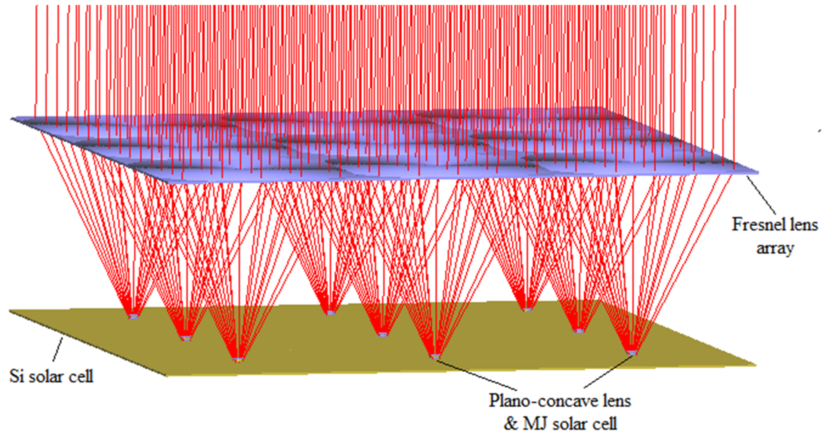
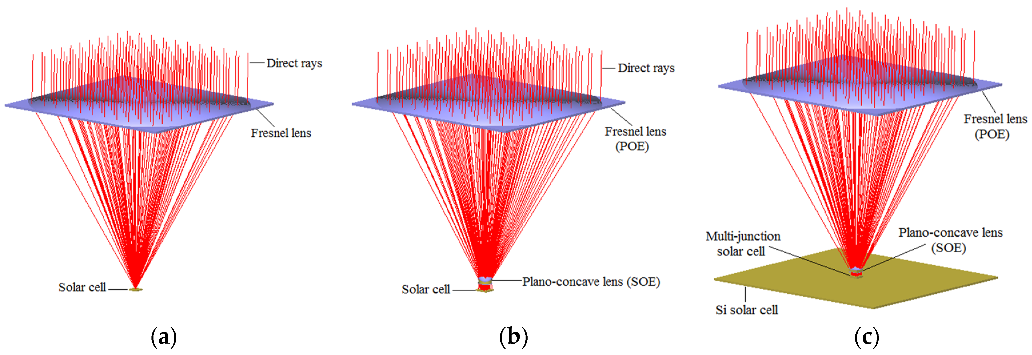
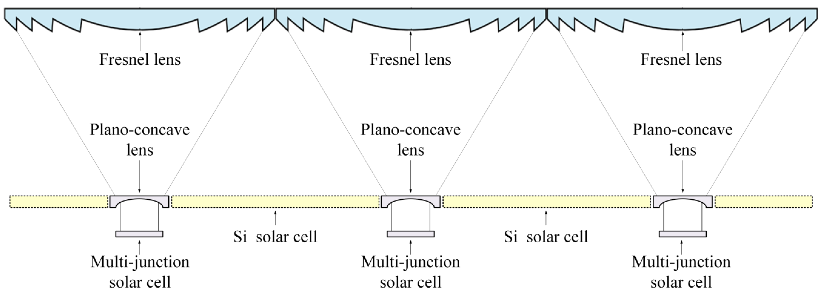
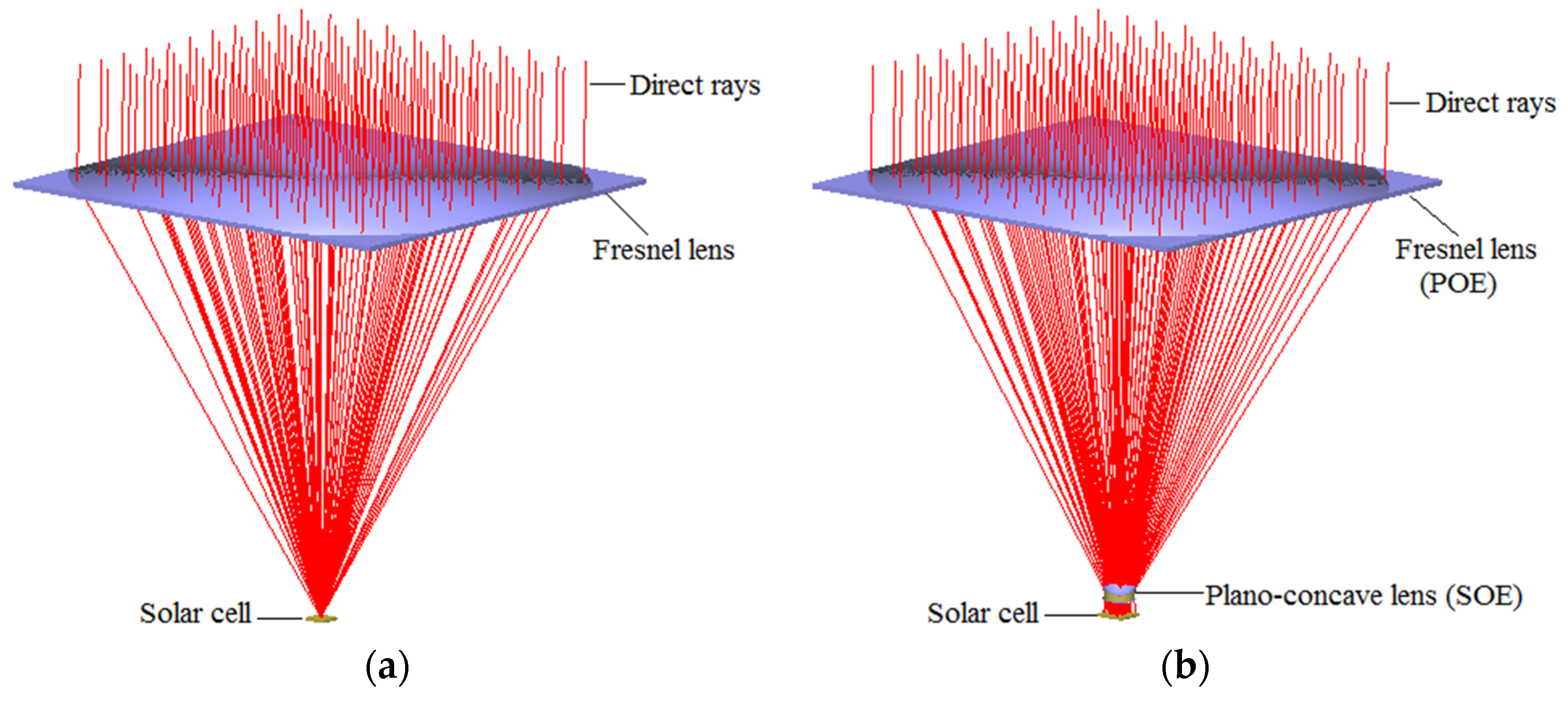
2. The Proposed CPV System

The proposed CPV system includes an array of CPV units and an additional low-cost solar cell. Each CPV unit consists of a Fresnel lens as the POE, a plano-concave lens as the SOE, and an MJ solar cell. A silicon (Si) solar cell surrounds plano-concave lenses of the CPV units to capture diffuse solar radiation. Each CPV unit highly concentrates and uniformly distributes direct solar radiation on its MJ solar cell through its POE and SOE, whereas the Si solar cell captures diffuse solar radiation.
The design and layout of the proposed system are shown in Figure 1 and Figure 2, respectively.

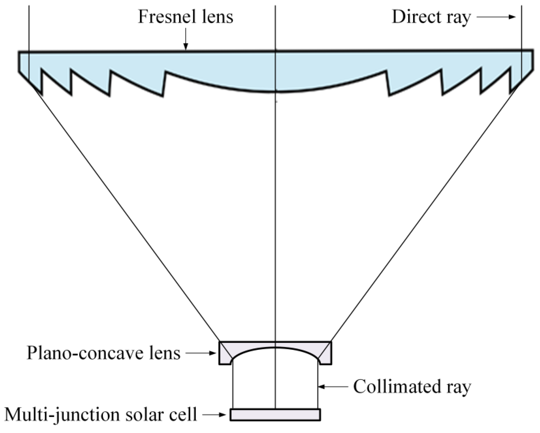
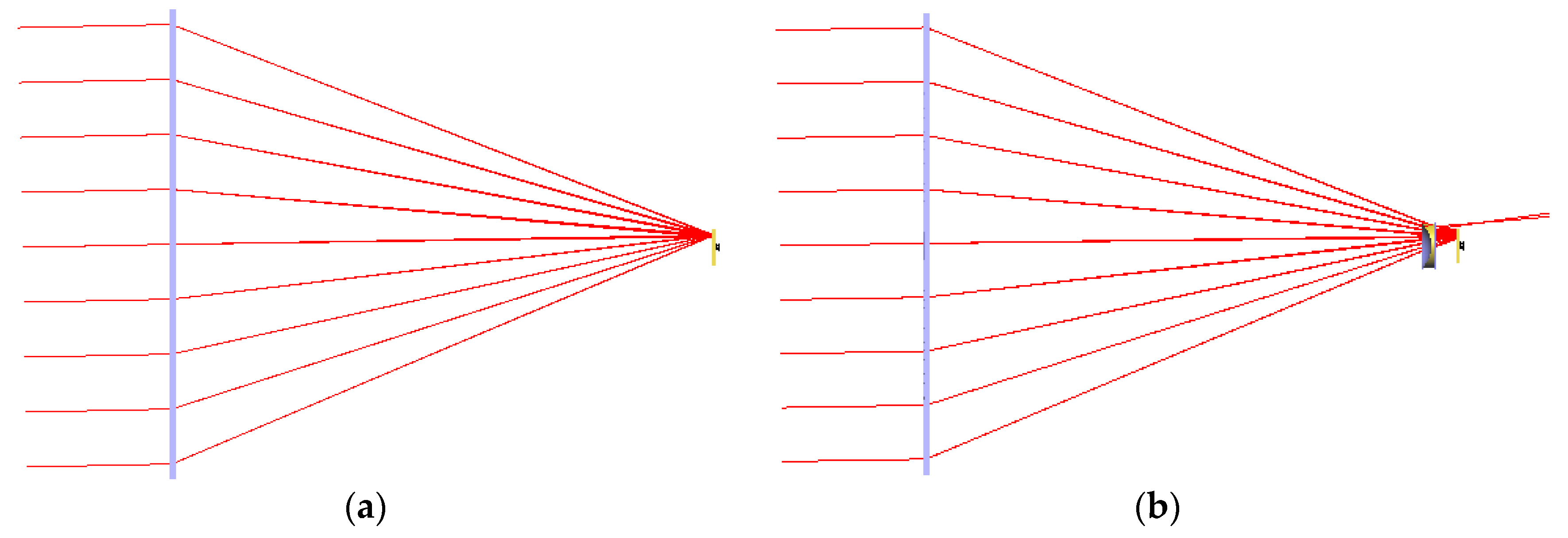
2.1. Improving Irradiance Uniformity

In the proposed CPV system, an array of Fresnel lenses is used as the POE. Fresnel lenses are used as solar concentrators since they offer high optical efficiency along with minimal weight and a low cost [31]. Plano-concave lenses are used to expand light beams in optical systems. They are used in CPV systems to improve the irradiance uniformity of the systems. In each designed CPV unit, a plano-concave lens is chosen as the SOE to improve the irradiance uniformity since plano-concave lenses are very common products in the market and have a low cost compared to other sophisticated SOE types, such as Köhler integration-based SOEs [19,20,21] and others [23]. The design of the CPV unit is shown in Figure 3.
The POE (Fresnel lens) is used to concentrate incident solar radiation into the SOE. The SOE (plano-concave lens) is used to redirect the sunlight into the MJ solar cell and to uniformly distribute the irradiation on the solar cell. Therefore, the designed CPV unit significantly improves the irradiance uniformity compared to the conventional CPV.
The effective focal length (EFL) of the Fresnel lens is calculated as follows:
E F L = r n 1 ,
where n is the refractive index and r is the radius of the Fresnel lens.
The focal length of the plano-concave lens is calculated by [32]:
f = D p 2 × N A ,
where N A is numerical aperture of the Fresnel lens and D p is diameter of the plano-concave lens.
In our proposed system, the material used for the Fresnel lens is polymethyl methacrylate (PMMA) with a refractive index of 1.494. The material used for the plano-concave lens is borosilicate glass N-BK7 with a refractive index of 1.52. Table 1 summarizes the design parameters of the CPV unit.

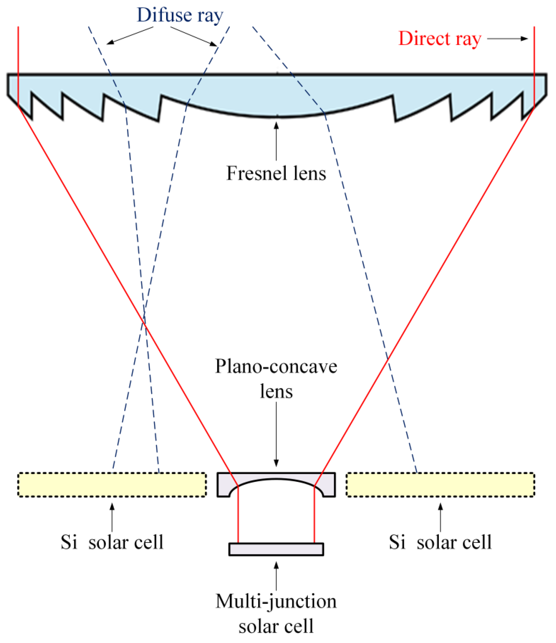
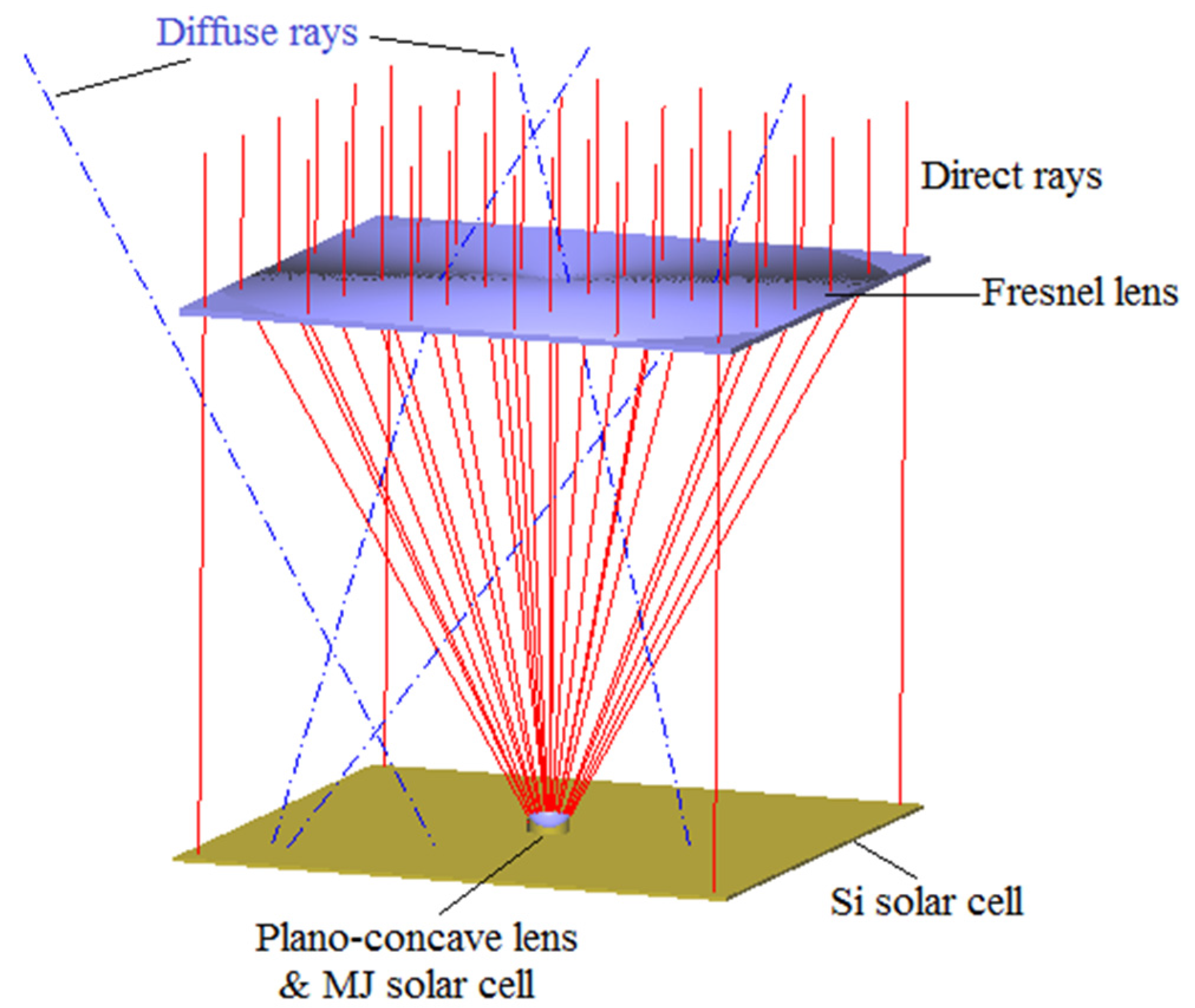
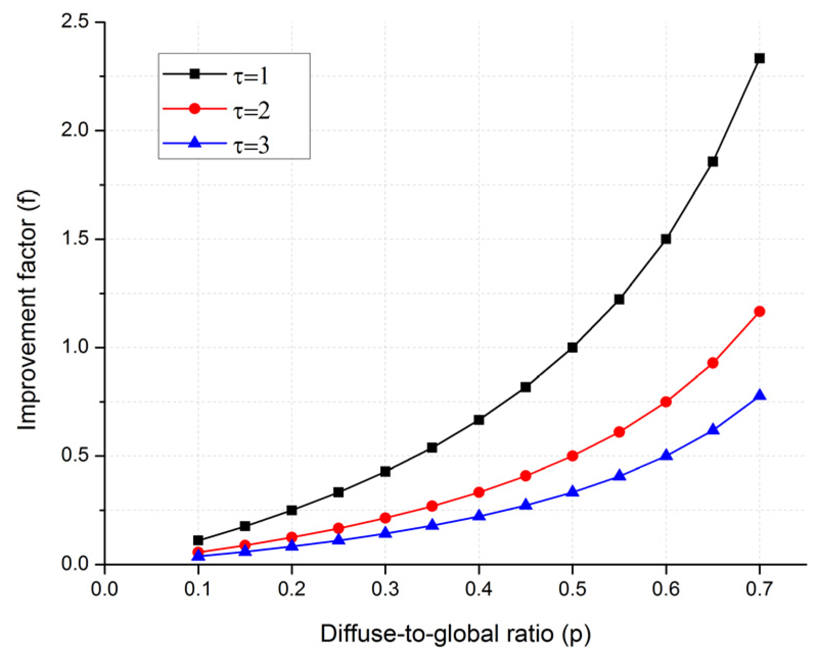
2.2. Capturing Diffuse Solar Radiation

Figure 4 shows the configuration of the proposed CPV unit for capturing diffuse solar radiation through the Si solar cell.
Figure 5 shows ray-tracing of the CPV unit with the Si solar cell. The size of the Si solar cell is equal to size of the array of Fresnel lenses of the CPV system.
The layout of the proposed CPV system with the array of nine CPV units and the additional Si solar cell is shown in Figure 2. In the design, direct sunrays are concentrated by the Fresnel lenses and redirected and distributed uniformly by the plano-concave lenses on the MJ solar cells. Diffuse sunrays from the sky and through the Fresnel lenses are then collected by the additional Si solar cell. Additionally, direct rays that are hit outside the Fresnel lens region are also captured by the Si solar cell.

3. Performance Analysis and Simulations

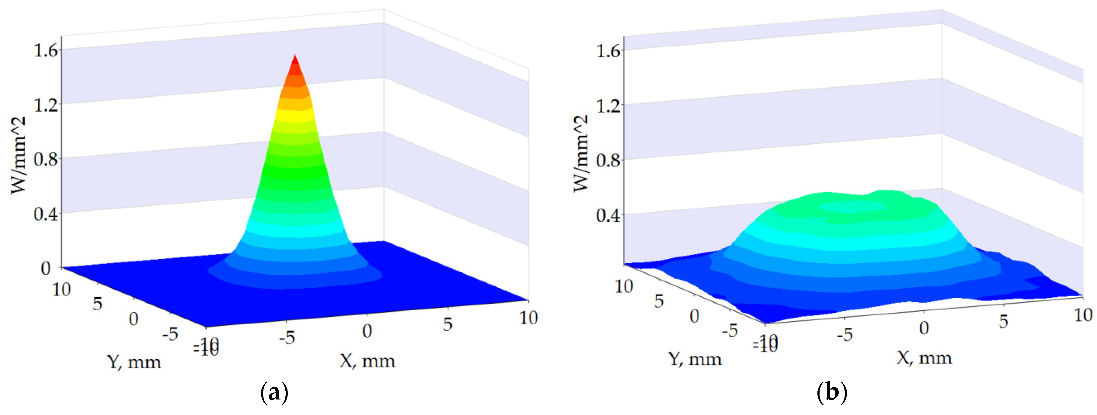
3.1. Irradiance Uniformity vs. Optical Loss

Adding the SOE to the CPV unit improves the irradiance uniformity but causes optical loss in the unit. This section analyzes, evaluates, and compares the irradiance uniformity and optical efficiency of the proposed CPV unit to the conventional CPV unit. In this case, the additional Si cell is not included in the analysis and evaluation. In other words, the considered CPV unit contains the MJ solar cell, but not the Si solar cell.
The geometrical structure of the proposed CPV unit was designed and simulated by using the commercial optical modeling software, LightTools™ [33]. In our design and simulations, the material used for the Fresnel lens was PMMA with a refractive index of 1.49. The material used for the plano-concave lens was borosilicate glass N-BK7 with a refractive index of 1.52. The simulation parameters were the same as those of the design shown in Table 1. Since the LightTools software does not supports circle solar cells, square solar cells with size of 20 mm × 20 mm were used in the simulation models.
Ray-tracing layouts of the conventional CPV unit and the proposed CPV unit with the SOE are shown in Figure 6a,b, respectively. In the proposed CPV unit, the POE concentrated and focused direct sunrays on the SOE’s surface, and then the SOE distributed the sun rays over the solar cell uniformly, as shown in Figure 6b.

3.1.1. Irradiance Uniformity

To evaluate and compare the irradiance uniformity, the irradiation distribution of both the conventional and proposed CPV units was measured. Figure 7a,b show the irradiation distribution of the conventional and proposed CPV units, respectively. The simulated results showed that the proposed CPV unit with the SOE gave better uniform irradiance distribution over the solar cell than the conventional CPV without the SOE.

3.1.2. Optical Loss

An optical loss factor l was used to analyze and evaluate the optical efficiency of the proposed CPV with the SOE compared with that of a conventional CPV.
The optical loss factor l is determined by:
l = η opt _ CPV C η opt _ CPV D η opt _ CPV C ,
where η opt _ CPV C and η opt _ CPV D are the optical efficiency of the conventional and proposed CPV units, respectively:
η opt _ CPV C = P in _ cell C P in _ FL ,
η opt _ CPV D = P in _ cell D P in _ FL ,
where P in _ cell C and P in _ cell D is the incident solar power received at the MJ solar cell of the conventional and proposed CPV units, respectively, and P in _ FL is the incident solar radiation hit on the Fresnel lens’s surface.
Equation (3) is then re-written as follows:
l = P in _ cell C P in _ cell D P in _ cell C .
Several simulations were conducted with various sunlight vertical incident luminous flux values to evaluate the loss factor of the proposed CPV unit. The incident power received at the solar cell was recorded in the simulations. Figure 8a shows the incident power received at the solar cell of both conventional and proposed CPV units, and Figure 8b shows the optical loss of the proposed CPV unit compared to the conventional CPV unit. The simulation results showed that the loss factor of the proposed CPV unit was 5.86%. In other words, the proposed CPV unit with the SOE resulted in optical loss of 5.86% compared to the conventional CPV unit without the SOE.

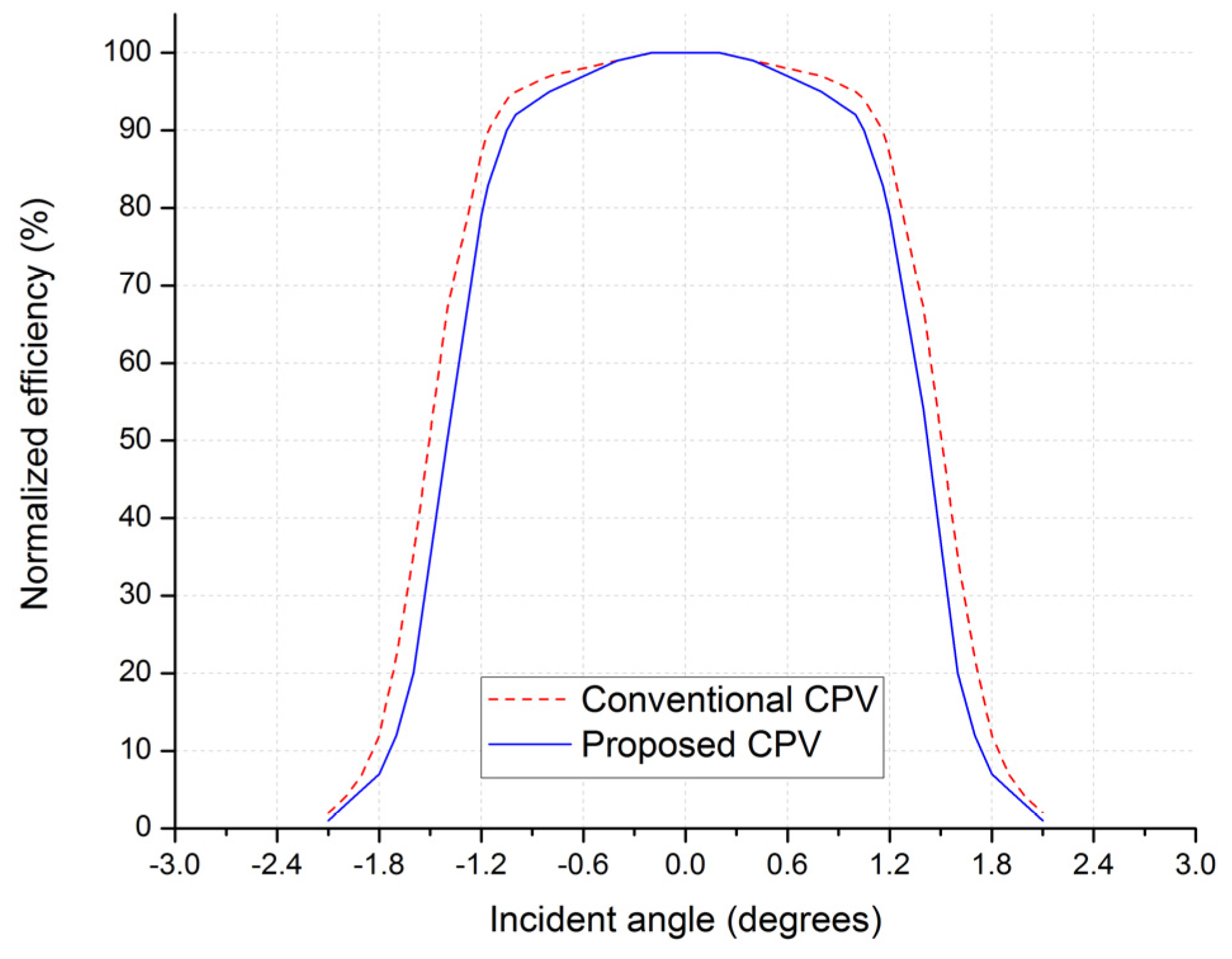
3.1.3. Acceptance Angle

In the CPV field, an acceptance angle is the incidence angle at which the concentrator collects 90% of the on-axis power. The acceptance angle has a tradeoff with the concentration. Increasing the acceptance angle reduces the concentration permanently [34]. This tradeoff is described through the concentration-acceptance angle product (CAP), being an appropriate merit function for a concentrator:
C A P = C g sin   α ,
where α is the acceptance angle, and C g is the geometric concentration, defined as the ratio of the concentrator aperture area to solar cell area [19].
Figure 9a,b demonstrate the ray-tracing results of the conventional and proposed CPV units, respectively, when the incidence angle is 1.2°.
The ray-tracing results showed that the proposed CPV unit with using a simple plano-concave lens as the SOE reduced a few incidence angle of sunrays compared to the conventional CPV unit. This resulted in a small reduction in the acceptance angle of the proposed CPV unit. To a certain degree, however, using accurate two-axis sun tracking system in the proposed CPV system can overcome the problem.
Figure 10 shows the angular transmission curve for both CPV units. The simulation results show that the proposed CPV unit has a 90% acceptance angle of ± 1.05 °, which is a little less than the conventional CPV unit, whose acceptance angle is about ± 1.16 °.

3.1.4. Discussion

Using the SOE, the proposed CPV unit added an additional optical loss to the system. However, the optical loss of 5.86% caused by the SOE found in the simulation is small and can be compensated for using the Si low-cost cell to capture diffuse solar radiation, which is discussed in the next section. Meanwhile, by using the SOE, the proposed CPV unit significantly improved the irradiance uniformity compared to the conventional CPV unit without the SOE, resulting in the elimination of hot spots and increasing the performance and lifetime of the solar cell.
Additionally, using an existing simple plano-concave lens as the SOE resulted in a small reduction of the acceptance angle of the proposed CPV system. The problem can be resolved by designing a new SOE type in order to improve not only the irradiation uniformity, but also the acceptance angle of the proposed CPV system.

3.2. System Efficiency

This section describes the system efficiency analysis of the proposed CPV system with the Si solar cell for capturing diffuse solar radiation compared to the conventional CPV system without using the additional solar cell.
A CPV system consisting of an CPV unit and an Si low-cost solar cell was considered. The design of the CPV system is shown in Figure 4, and its ray-tracing layout is shown in Figure 5.

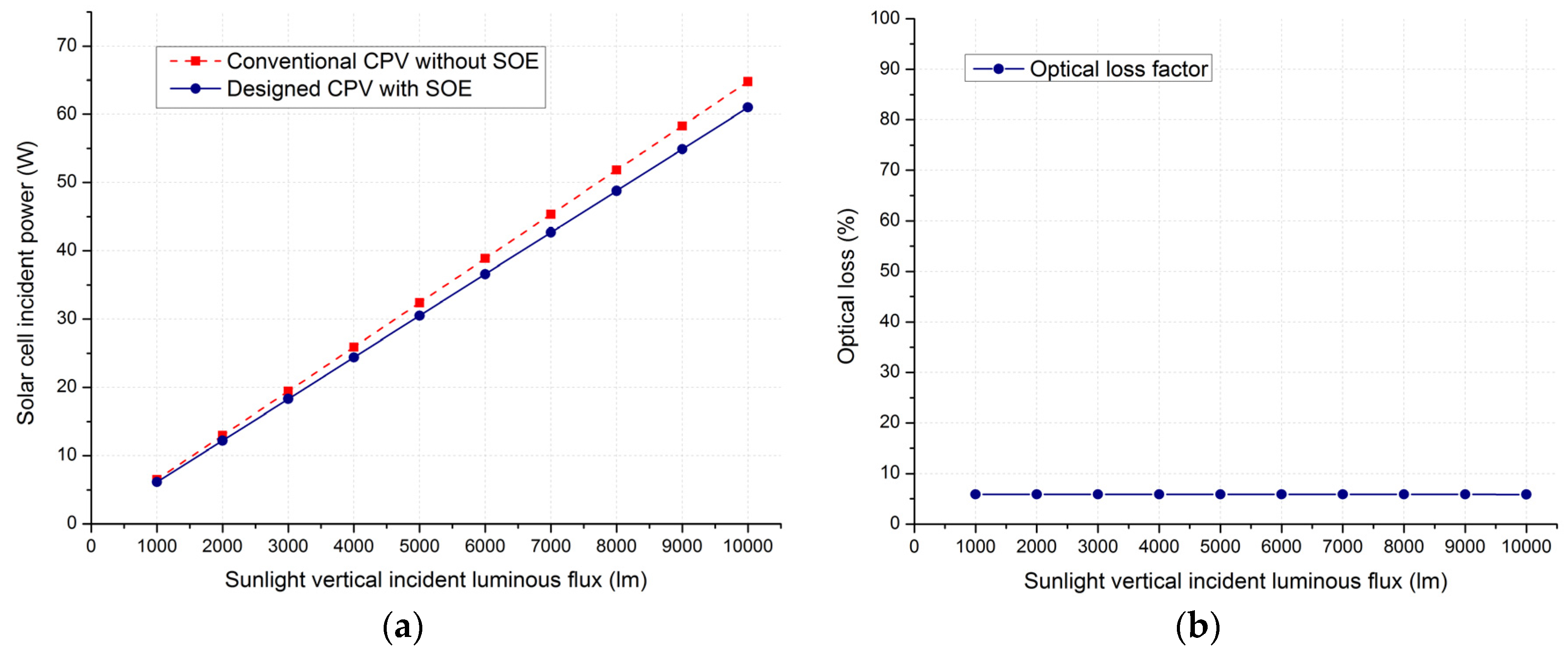
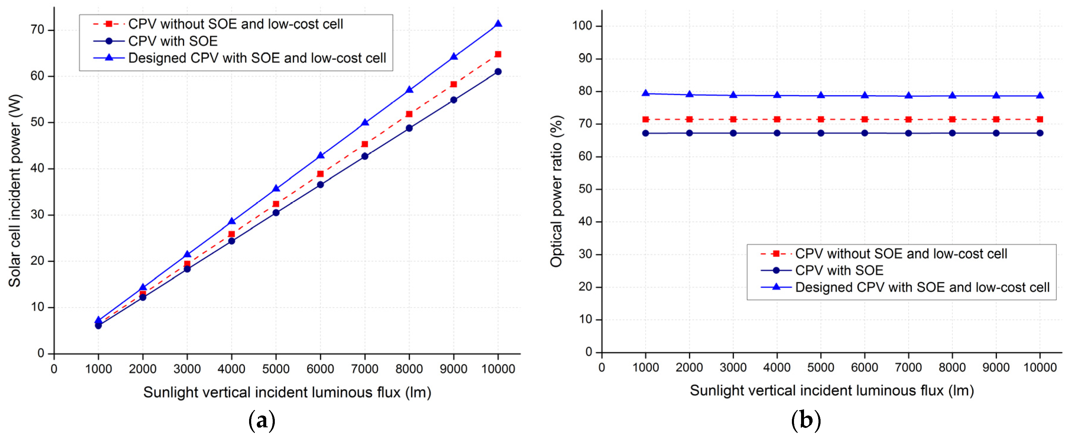
3.2.1. Optical Power Ratio

The optical power ratio of the CPV unit is simply defined as the ratio of the solar radiation received by the solar cells to the solar radiation hit on the Fresnel lens’s surface.
The optical power ratio is calculated by:
η opt _ CPV = P in _ cell P in _ FL ,
where P in _ cell is the incident solar radiation received at the solar cells and P in _ FL is incident solar radiation hit on the Fresnel lens’s surface of the CPV unit.
For the proposed CPV unit, the incident solar radiation received at the solar cells including the MJ solar cell and the Si solar cell is determined by:
P in _ cell = P in _ MJ _ cell + P in _ Si _ cell ,
where P in _ MJ _ cell and P in _ Si _ cell are the incident solar radiation received at the MJ and Si solar cells, respectively.
To evaluate the efficiency of the designed CPV units, the following CPV units were considered, including a CPV unit without the SOE and the additional low-cost cell, a CPV unit with the SOE, and the designed CPV unit with both the SOE and the additional low-cost cell. The models of these CPV units are shown in Figure 11a–c, respectively.
Simulations were conducted using LightTools™ to evaluate and compare the optical power ratio of the designed CPV unit with that of the other CPV units. The optical power ratio of the CPV units in the simulations was recorded and is shown in Figure 12a,b, respectively. The simulation results showed that the optical power ratio of the designed CPV unit is better than that of the other CPV units.

3.2.2. System Conversion Efficiency

Conversion efficiency is a measure used to analyze and evaluate the performance of a CPV system. Conversion efficiency is defined as the ratio of energy output from the CPV system to input energy from the sun. The efficiency of a CPV system depends on the conversion efficiency of solar cells used in the system, the optical efficiency of the CPV units, and the spectrum and intensity of the incident sunlight.
The total solar radiation on a horizontal surface, denoted by G, is the sum of horizontal beam (direct) solar radiation and diffuse solar radiation [1]:
G = G B + G D ,
where G B is beam radiation on a horizontal surface (direct normal irradiation), G D is diffuse radiation on a horizontal surface, and G is global horizontal irradiation.
The conversion efficiency of a conventional CPV system, denoted by η C , is given by [28]:
η C = η opt _ CPV η cell _ CPV G B G ,
where η opt _ CPV and η cell _ CPV are the optical efficiency of the CPV based on direct solar radiation and the conversion efficiency of the MJ solar cell, respectively.
The proposed CPV system captures both direct and diffuse solar radiation, so its conversion efficiency depends on not only direct solar radiation, but also diffuse solar radiation. The conversion efficiency of the designed CPV system, denoted by η D , can be calculated by [28]:
η D = η opt _ CPV η cell _ CPV G B + η opt _ PV η cell _ PV G D G ,
where η opt _ PV and η cell _ PV are the optical efficiency of the Si low-cost solar cell based on diffuse solar radiation and the conversion efficiency of the Si solar cell, respectively.
An improvement factor of system efficiency f was used to analyze and evaluate the system efficiency of the proposed CPV system with the Si low-cost solar cell compared with that of the conventional CPV system without the low-cost solar cell.
The improvement factor f is determined as follows:
f = η D η C η C .
By substituting (11) and (12) into (13), the improvement factor f is re-written as follows:
f = η opt _ PV η cell _ PV η opt _ CPV η cell _ CPV × G D G B .
Let τ and ρ be:
τ = η opt _ CPV η cell _ CPV η opt _ PV η cell _ PV ,
ρ = G D G ,
where τ is the ratio of the conversion efficiency of the MJ solar cell to that of the Si solar cell in the CPV system, and ρ is the diffuse-to-global ratio, or the ratio of diffuse solar radiation to the global solar radiation.
The improvement factor f is then determined as follows:
f = ρ τ ( 1 ρ ) .
Figure 13 shows the improvement factor f values for seven ρ values (0.1 ÷ 0.7) with τ = 1 , 2, and 3, respectively. For τ = 2 , an improvement f of 33.3% is expected for a medium DNI region with ρ 0.4 , whereas an improvement f of 12.5% is expected for a high DNI region with ρ 0.2 .

3.2.3. System Cost

To evaluate and compare the cost efficiency of the proposed CPV system with an additional low-cost solar cell to that of the conventional CPV system without the additional low-cost solar cell, the following “merit function” R is used as the capital cost of annual electrical energy delivered. Since R is expressed as cost per unit of power, low values of R are more meritorious [29]:
R = s y s t e m   c o s t   ( $ ) a n n u a l   n o m i n a l   g e n e r a t e d   e l e c t r i c a l   e n e r g y   ( k W h ) .
The merit function R and energy output E of the conventional CPV system are determined as follows [29]:
R C = C 0 + C CPV E C + C non cell ,
E C = G B × η cell _ CPV η opt _ CPV ,
where R C and E C is the capital cost of annual generated electrical energy and the nominal annual DC electrical energy density of the conventional CPV system, respectively. C 0 and C non cell are the costs that are proportional to system entry aperture area (the module cover, frame, tracking system, the structural supporting beams, land use, etc.), and system power (inverter, etc.), respectively. C 0 and C non cell are common to the respective CPV systems; and C CPV is the cost specific to the use of the high efficiency MJ cells (MJ cells, heat sink, etc.).
The merit function and energy output of the proposed CPV system with the additional low-cost solar cell are calculated as follows [29]:
R D = C 0 + C CPV + C PV E D + C non cell ,
E D = G B × η cell _ CPV η opt _ CPV + G D × η cell _ PV η opt _ PV ,
where R D and E D is the capital cost of annual generated electrical energy and the nominal annual DC electrical energy density of the proposed CPV system, respectively; and C PV is the cost specific to the use of the additional low-cost solar cell.
Some experimental results [28,29,30] showed that the CPV system with the additional low-cost solar cell outperformed the conventional CPV without the additional solar cell, with E D / E C = 1.15 . The addition of the low-cost solar cell to the CPV system resulted in 15% more electricity generated per dollar.

3.2.4. Discussion

Numerically, for our simulations, the proposed CPV unit with the SOE and the Si low-cost cell (Figure 11c) provided an optical power ratio increase of about 17.12% compared to the conventional CPV unit without using the additional low-cost cell (Figure 11b), and about 10.26% compared to the conventional CPV unit without using both the SOE and the additional low-cost cell (Figure 11a). In other words, the optical power ratio of the proposed CPV unit is better than that of the other CPV units. By using both the SOE and the additional low-cost cell, the proposed CPV not only improves the irradiance uniformity but also increases the optical power ratio of the system.
For the system conversion efficiency, the conversion efficiency ratio τ depends on the type of MJ and additional low-cost solar cells as well as the optical system. The improvement factor decreases with an increasing ratio τ because the electricity generated by the MJ solar cell is high compared to that generated by the Si solar cell. The ratio ρ depends on the atmospheric conditions, e.g., the annual mean value for a medium DNI region, such as Korea or Japan, is ρ 0.4 , while that for a high DNI region, such as Phoenix (USA), is ρ 0.2 [28]. The improvement factor increases with an increasing ratio ρ because the amount of diffuse solar radiation collected by the additional solar cell increases compared to that for direct solar radiation concentrated on the MJ solar cell.
Since the proposed CPV system uses an additional low-cost solar cell, the cost of the system is higher than that of conventional CPV systems. However, the proposed system uses low-cost optical components, including Fresnel and plano-concave lenses, and an additional low-cost cell; the cost of the system is thus not much higher than that of the conventional CPV systems. The use of the additional low-cost solar cell resulted in more electricity generated per dollar.

4. Conclusions

In this paper, we proposed a novel CPV system to improve both irradiation uniformity and system efficiency. Each CPV unit of the proposed system uses a Fresnel lens as the POE associated with a plano-concave lens as the SOE to highly concentrate and uniformly distribute the sunlight over a MJ solar cell. By using the SOE, the irradiance uniformity is significantly improved in the system. Additionally, the system also uses an additional low-cost solar cell to harvest diffuse solar radiation. The direct solar radiation is concentrated and focused by the Fresnel lenses and then distributed uniformly by the plano-concave lenses on the MJ solar cells, whereas the diffuse solar radiation is captured by the low-cost solar cell. Therefore, the conversion efficiency of the designed system is significantly increased. The analyzed and simulated results show that the proposed CPV system significantly improves both the irradiance uniformity and the system efficiency compared to the conventional CPV systems. Numerically, for our simulation models, the designed CPV with the SOE and low-cost solar cell provided the optical power ratio increase of about 17.12% compared to the conventional CPV without the low-cost cell, and about 10.26% compared to the conventional CPV without using both the SOE and additional low-cost cell. The study is the first to integrate both the improvement of irradiance uniformity and the collection of diffuse solar radiation into a CPV system. The proposed CPV system is very suitable for medium DNI regions, such as Korea and Japan.
Our future work is to design a new SOE type that is used to replace the simple plano-concave lens of the CPV unit in order to improve not only the irradiation uniformity, but also the acceptance angle of the proposed CPV system.

Acknowledgments

This work was supported by the National Research Foundation of Korea (NRF) grant funded by the Korea government (MSIP) (No. 2014R1A2A1A11051888).

Author Contributions

Nguyen Xuan Tien and Seoyong Shin conceived of and developed the ideas behind the research. Nguyen Xuan Tien performed the performance analysis and simulations, and wrote the paper. Seoyong Shin supervised the research.

Conflicts of Interest

The authors declare no conflict of interest.

References

  1. Kalogirou, S.A. Solar Energy Engineering: Processes and Systems, 2nd ed.; Academic Press: Millbrae, CA, USA, 2014. [Google Scholar]
  2. Baig, H.; Heasman, K.C.; Mallick, T.K. Non-uniform illumination in concentrating solar cells. Renew. Sustain. Energy Rev. 2012, 15, 5890–5909. [Google Scholar] [CrossRef]
  3. Xie, W.T.; Dai, Y.J.; Wang, R.Z.; Sumathy, K. Concentrated solar energy applications using Fresnel lenses: A review. Renew. Sustain. Energy Rev. 2011, 15, 2588–2606. [Google Scholar] [CrossRef]
  4. Mittelman, G.; Kribus, A.; Mouchtar, O.; Dayan, A. Water desalination with concentrating photovoltaic/thermal (CPVT) systems. Sol. Energy 2009, 83, 1322–1334. [Google Scholar] [CrossRef]
  5. Fraidenraich, N.; Tiba, C.; Brandão, B.B.; Vilela, O.C. Analytic solutions for the geometric and optical properties of stationary compound parabolic concentrators with fully illuminated inverted V receiver. Sol. Energy 2008, 82, 132–143. [Google Scholar] [CrossRef]
  6. Krüger, D.; Pandian, Y.; Hennecke, K.; Schmitz, M. Parabolic trough collector testing in the frame of the REACt project. Desalination 2008, 220, 612–618. [Google Scholar] [CrossRef]
  7. Weber, K.J.; Everett, V.; Deenapanray, P.N.K.; Franklin, E.; Blakers, A.W. Modeling of static concentrator modules incorporating lambertian or v-groove rear reflectors. Sol. Energy Mater. Sol. Cells 2006, 90, 1741–1749. [Google Scholar] [CrossRef]
  8. Yamada, N.; Kanno, K.; Hayashi, K.; Tokimitsu, T. Performance of see-through prism CPV module for window integrated photovoltaics. Opt. Express 2011, 19, A649–A656. [Google Scholar] [CrossRef] [PubMed]
  9. Van Sark, W.G.J.H.M.; Barnham, K.W.J.; Slooff, L.H.; Chatten, A.J.; Büchtemann, A.; Meyer, A.; McCormack, S.J.; Koole, R.; Farrell, D.J.; Bose, R.; et al. Luminescent Solar Concentrators—A review of recent results. Opt. Express 2008, 16, 21773–21792. [Google Scholar] [CrossRef] [PubMed]
  10. Segev, G.; Kribus, A. Performance of CPV modules based on vertical multi-junction cells under non-uniform illumination. Sol. Energy 2013, 88, 120–128. [Google Scholar] [CrossRef]
  11. Luque, A.; Sala, G.; Arboiro, J.C. Electric and thermal model for non-uniformly illuminated concentration cells. Sol. Energy Mater. Sol. Cells 1998, 51, 269–290. [Google Scholar] [CrossRef]
  12. Cuevas, A.; Lopez-Romero, S. The combined effect of non-uniform illumination and series resistance on the open-circuit voltage of solar cells. Sol. Cells 1984, 11, 163–173. [Google Scholar] [CrossRef]
  13. Leutz, R.; Suzuki, A. Nonimaging Fresnel Lenses: Design and Performance of Solar Concentrators; Springer-Verlag: Berlin, Germany; Heidelberg, Germany, 2012. [Google Scholar]
  14. Winston, R.; Miñano, J.C.; Benítez, P. Nonimaging Optics; Elsevier Academic Press: Cambridge, MA, USA, 2005. [Google Scholar]
  15. Stefancich, M.; Zayan, A.; Chiesa, M.; Rampino, S.; Roncati, D.; Kimerling, L.; Michel, J. Single element spectral splitting solar concentrator for multiple cells CPV system. Opt. Express 2012, 20, 9004–9018. [Google Scholar] [CrossRef] [PubMed]
  16. Maragliano, C.; Zayan, A.; Stefancich, M. Three-Dimensional Point-Focus Spectral Splitting Solar Concentrator System. Int. J. Opt. Appl. 2014, 4, 6–11. [Google Scholar]
  17. Ning, X.; O’Gallagher, J.; Winston, R. Optics of two-stage photovoltaic concentrators with dielectric second stages. Appl. Opt. 1987, 26, 1207–1212. [Google Scholar] [CrossRef] [PubMed]
  18. Meng, X.; Xia, X.; Sun, C.; Dai, G. Optimal design of symmetrical two-stage flat reflected concentrator. Sol. Energy 2013, 93, 334–344. [Google Scholar] [CrossRef]
  19. Benítez, P.; Miñano, J.C.; Zamora, P.; Mohedano, R.; Cvetkovic, A.; Buljan, M.; Chaves, J.; Hernández, M. High performance Fresnel-based photovoltaic concentrator. Opt. Express 2010, 18, A25–A40. [Google Scholar] [CrossRef] [PubMed]
  20. Miñano, J.C.; Benítez, P.; Zamora, P.; Buljan, M.; Mohedano, R.; Santamaría, A. Free-form optics for Fresnel-lens-based photovoltaic concentrators. Opt. Express 2013, 21, A494–A502. [Google Scholar] [CrossRef] [PubMed]
  21. Mendes-Lopes, J.; Benítez, P.; Zamora, P.; Miñano, J.C. 9-fold Fresnel–Köhler concentrator with Fresnel lens of variable focal point. Opt. Express 2014, 22, A1153–A1163. [Google Scholar] [CrossRef] [PubMed]
  22. Miñano, J.C.; Hernández, M.; Benítez, P.; Blen, J.; Dross, O.; Mohedano, R.; Santamaría, A. Free-form integrator array optics. Proc. SPIE 2005. [Google Scholar] [CrossRef]
  23. Chen, Y.C.; Chiang, H.W. Design of the secondary optical elements for concentrated photovoltaic units with Fresnel lenses. Appl. Sci. 2015, 5, 770–786. [Google Scholar] [CrossRef]
  24. Ullah, I.; Shin, S. Development of optical fiber-based daylighting system with uniform illumination. J. Opt. Soc. Korea 2012, 16, 247–255. [Google Scholar] [CrossRef]
  25. Ullah, I.; Shin, S. Uniformly illuminated efficient daylighting system. Smart Grid Renew. Energy 2013, 4, 161–166. [Google Scholar] [CrossRef]
  26. Ullah, I.; Shin, S. Highly concentrated optical fiber-based daylighting systems for multi-floor office buildings. Energy Build. 2014, 72, 246–261. [Google Scholar] [CrossRef]
  27. Vu, N.H.; Shin, S. A large-scale daylighting system based on a stepped thickness waveguide. Energies 2016, 9. [Google Scholar] [CrossRef]
  28. Yamada, N.; Okamoto, K. Experimental measurements of a prototype high-concentration Fresnel lens CPV module for the harvesting of diffuse solar radiation. Opt. Express 2014, 22, A28–A34. [Google Scholar] [CrossRef] [PubMed]
  29. Benitez, P.; Miñano, J.C.; Alvarez, R. Photovoltaic Concentrator with Auxiliary Cells Collecting Diffuse Radiation. U.S. Patent 2010/0126556 A1, 27 May 2010. [Google Scholar]
  30. Yamada, N.; Okamoto, K.; Ijiro, T. Feasibility study of harvesting diffuse solar radiation in a high-concentration CPV module for better solar energy conversion. In Proceedings of the 23rd International Photovoltaic Science and Engineering Conference (PVSEC-23), Taiwan, China, 28 October–1 November 2013.
  31. Leutz, R.; Suzuki, A.; Akisawa, A.; Kashiwagi, T. Developments and designs of solar engineering Fresnel lenses. In Proceedings of Symposium on Energy Engineering (SEE 2000); Project Nerd: Hong Kong, China, 2000; Volume 2, pp. 759–765. [Google Scholar]
  32. Malacara, D. Optical Shop Testing, 3rd ed.; John Wiley & Sons: New York, NY, USA, 2007. [Google Scholar]
  33. LightTool v8.2.0. Optical Simulation Tool. Available online: https://optics.synopsys.com/lighttools/ (accessed on 24 May 2016).
  34. Selimoglu, O.; Turan, R. Exploration of the horizontally staggered light guides for high concentration CPV applications. Opt. Express 2012, 20, 19137–19147. [Google Scholar] [CrossRef] [PubMed]
Figure 1. Design of the proposed concentrator photovoltaic (CPV) system. Si, silicon.
Applsci 06 00251 g001
Figure 2. Array layout of the CPV system. MJ, multi-junction.
Applsci 06 00251 g002
Figure 3. Design of the proposed CPV unit with the secondary optical element (SOE).
Applsci 06 00251 g003
Figure 4. Design of the proposed CPV unit with the SOE and low-cost cell.
Applsci 06 00251 g004
Figure 5. Ray-tracing of the designed CPV unit with the SOE and Si solar cell.
Applsci 06 00251 g005
Figure 6. Layout of CPV units under ray-tracing simulation: (a) a conventional CPV unit; and (b) the proposed CPV unit.
Applsci 06 00251 g006
Figure 7. Irradiance distribution on the solar cell: (a) the conventional CPV unit; and (b) the proposed CPV unit.
Applsci 06 00251 g007
Figure 8. (a) comparison of incident power received at the cells of the conventional and proposed CPV units; and (b) optical loss of the proposed CPV unit compared to the conventional CPV unit.
Applsci 06 00251 g008
Figure 9. Ray-tracing at incidence angle of 1.2°: (a) the conventional CPV unit; and (b) the proposed CPV unit.
Applsci 06 00251 g009
Figure 10. The angular transmission curve vs. incident angle for both conventional and proposed CPV units.
Applsci 06 00251 g010
Figure 11. CPV units: (a) the CPV unit without the SOE and low-cost cell; (b) the CPV unit with the SOE; and (c) the designed CPV unit with both the SOE and low-cost cell.
Applsci 06 00251 g011
Figure 12. (a) comparison of incident solar power received at the solar cells of CPV units; and (b) comparison of the optical power ratio between CPV units.
Applsci 06 00251 g012
Figure 13. Improvement factor vs. diffuse-to-global ratio.
Applsci 06 00251 g013
Table 1. Design parameters of the concentrator photovoltaic (CPV) unit.
ParameterValue
Focal length of the Fresnel lens300 mm
Size of the Fresnel lens300 mm × 300 mm
Thickness of the Fresnel lens3 mm
Material of the Fresnel lensPMMA 1
Focal length of the plano-concave lens25 mm
Diameter of the plano-concave lens21.5 mm
Thickness of the plano-concave lens2 mm
Material of the plano-concave lensN-BK7 2
Distance between the POE 3 and SOE 4283 mm
Diameter of the multi-junction solar cell20 mm
1 PMMA: Polymethyl methacrylate; 2 N-BK7: Borosilicate glass. 3 POE, primary optical element. 4 SOE, secondary optical element.

