
Hardware Implementation and Validation of 3D Underwater Shape Reconstruction Algorithm Using a Stereo-Catadioptric System

Abstract
:
1. Introduction
2. Related Work and the Proposed Algorithm
2.1. Related Work
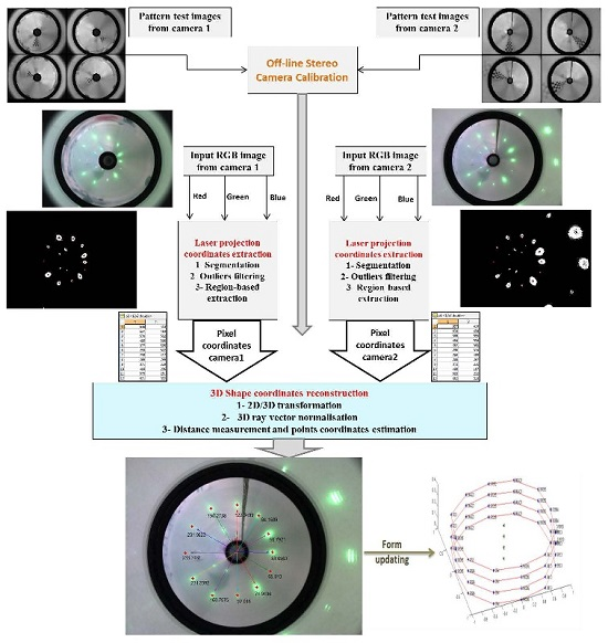
2.2. The Proposed Algorithm
3. The Stereo System and Its Underwater Calibration
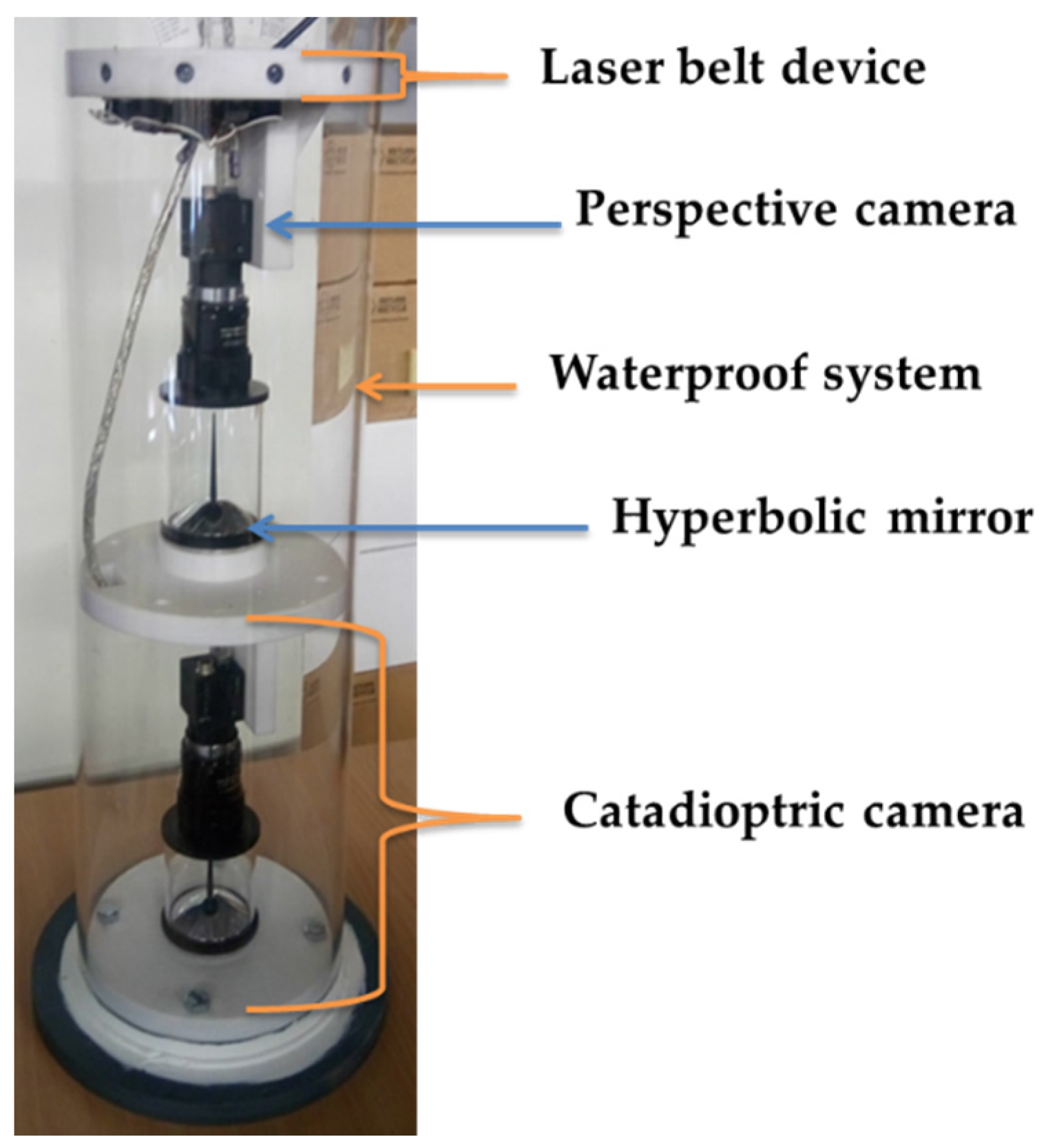
3.1. Description of the Stereo-Catadioptric System
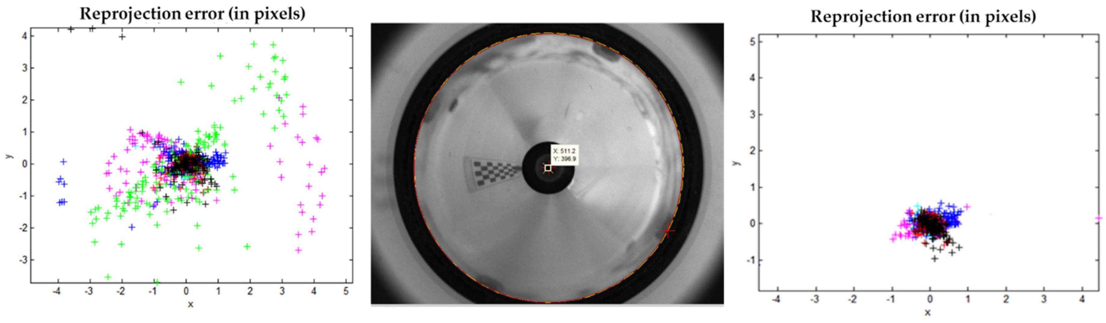
3.2. Off-Line Stereo Catadioptric System Calibration
4. Description of the Proposed 3D Underwater Shape Reconstruction System
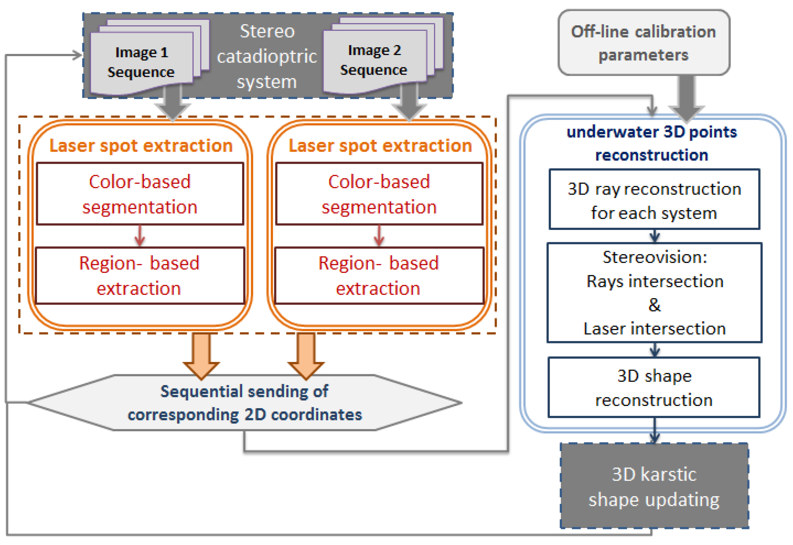
4.1. The Flowchart of the Algorithm
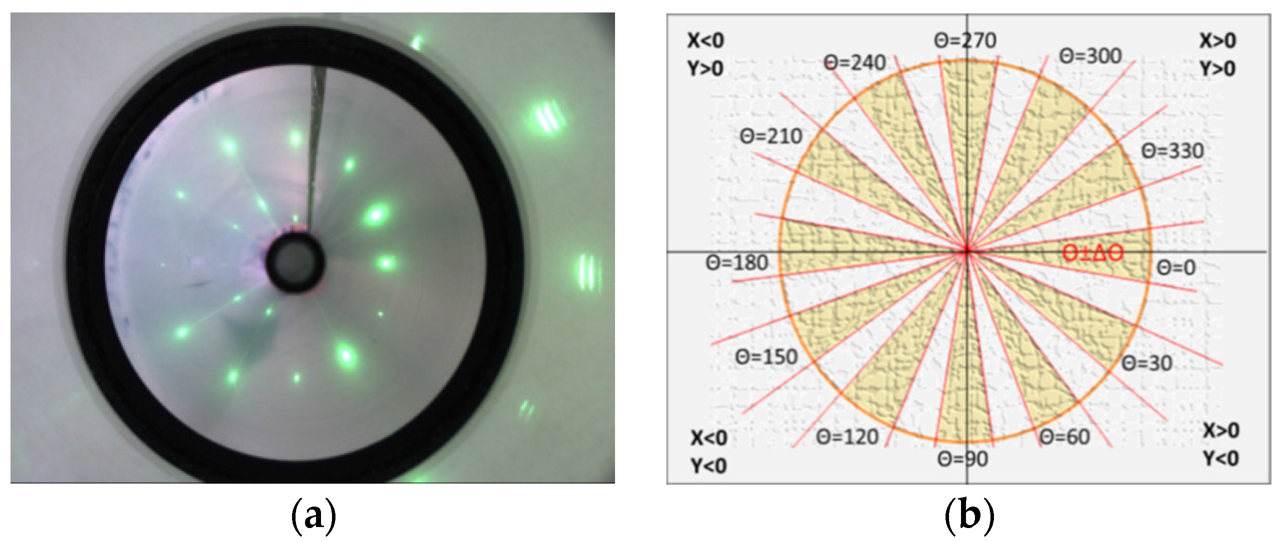
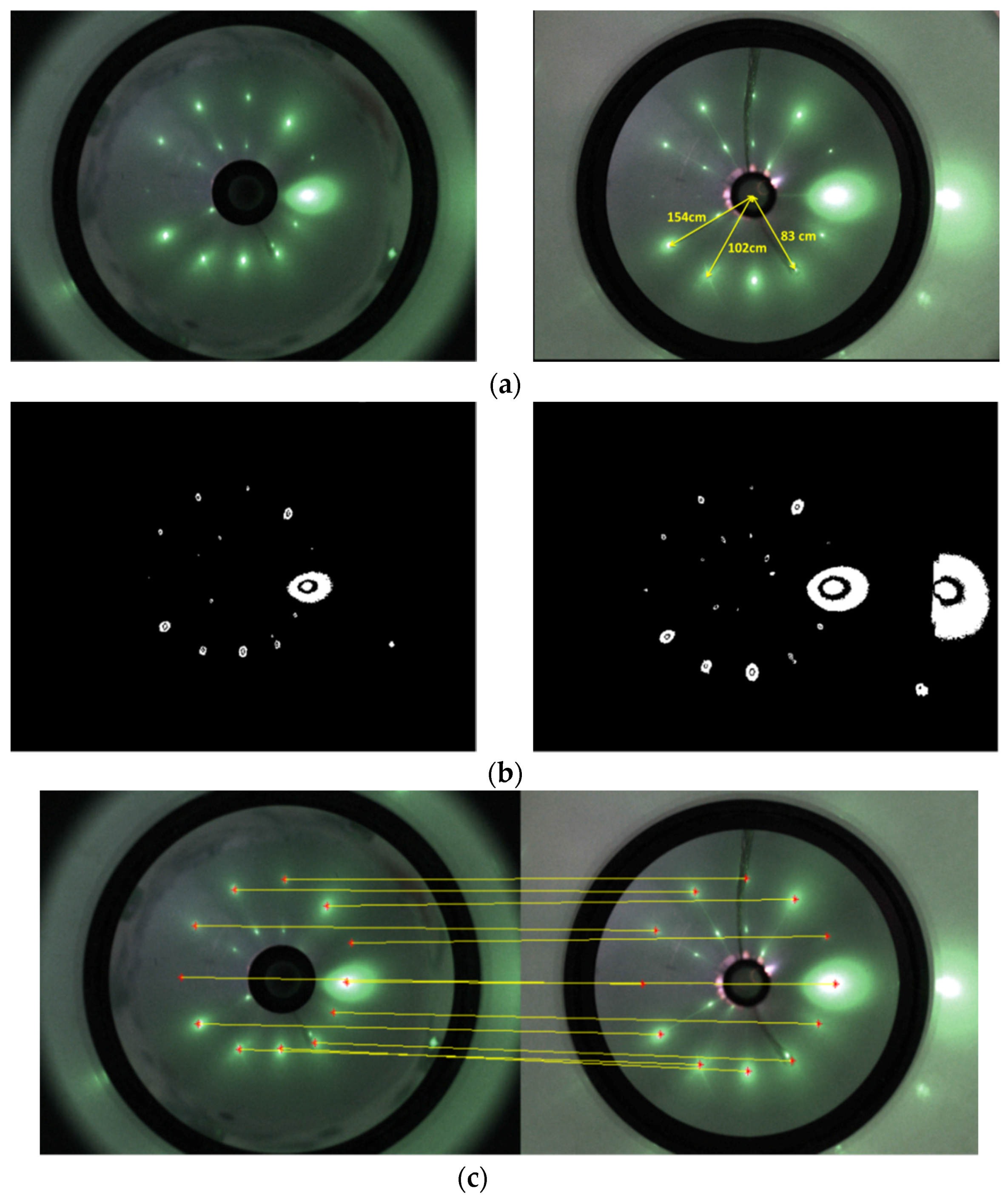
4.2. Laser Spot Detection and Extraction Algorithm
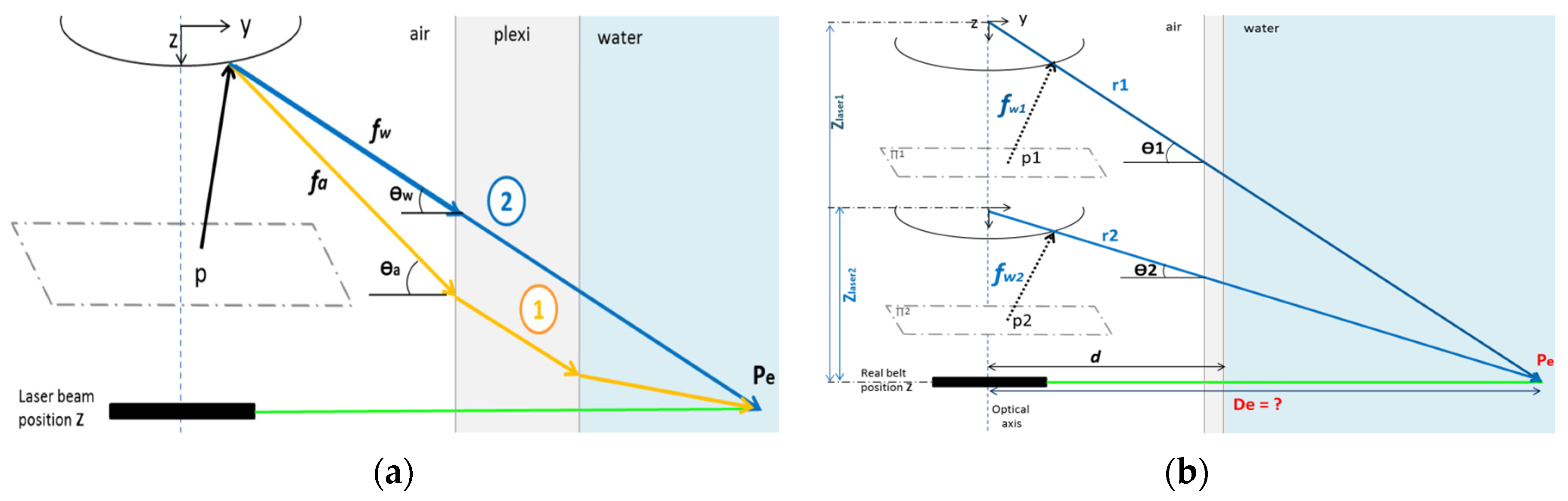
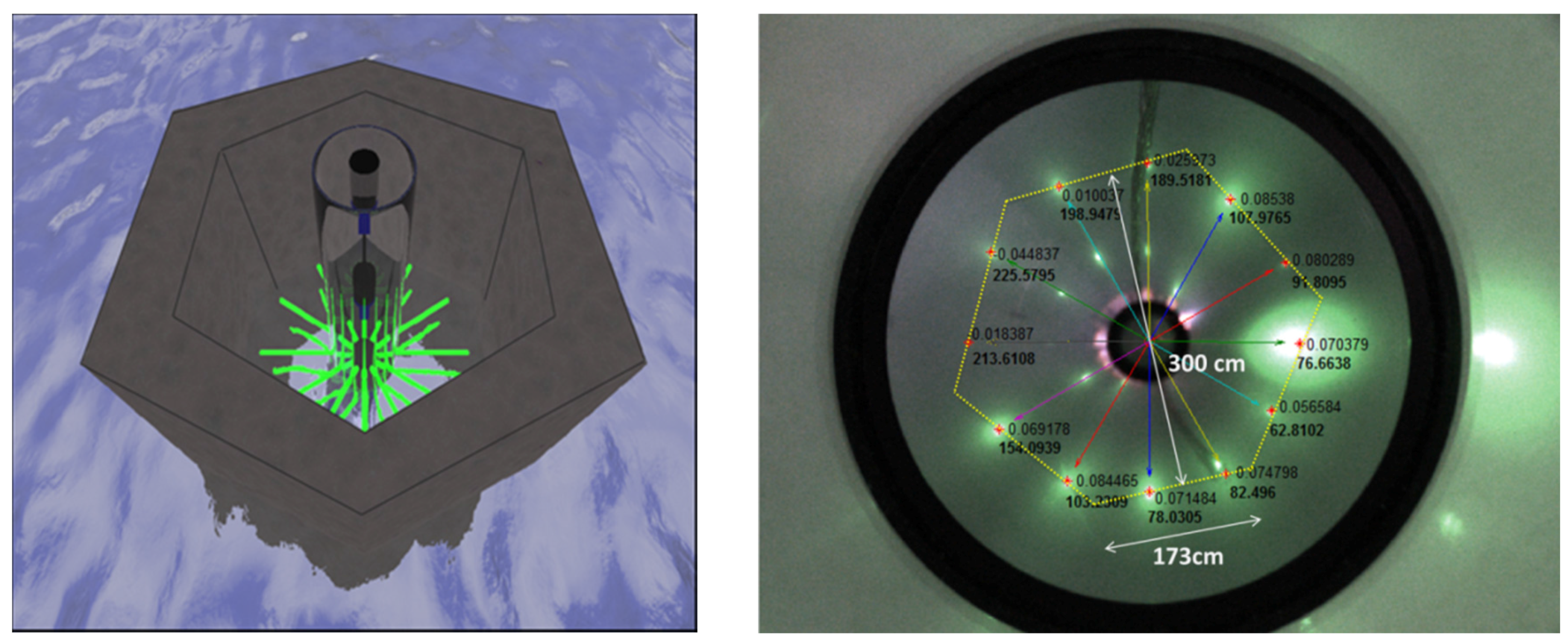
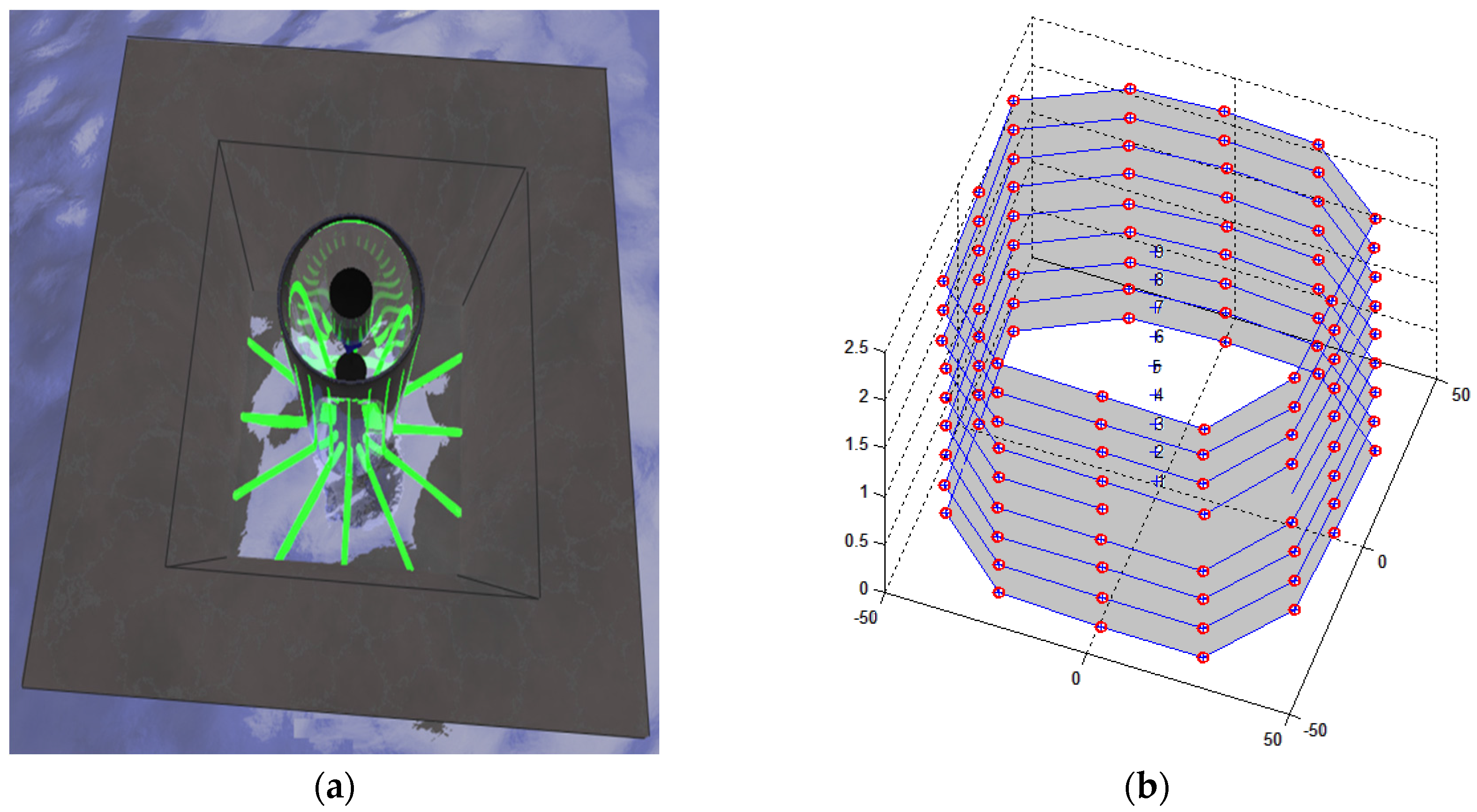
4.3. 3D Underwater Shape Reconstruction Algorithm
4.4. Complete Workflow of the Proposed System
5. Hardware Design of the Proposed Algorithm
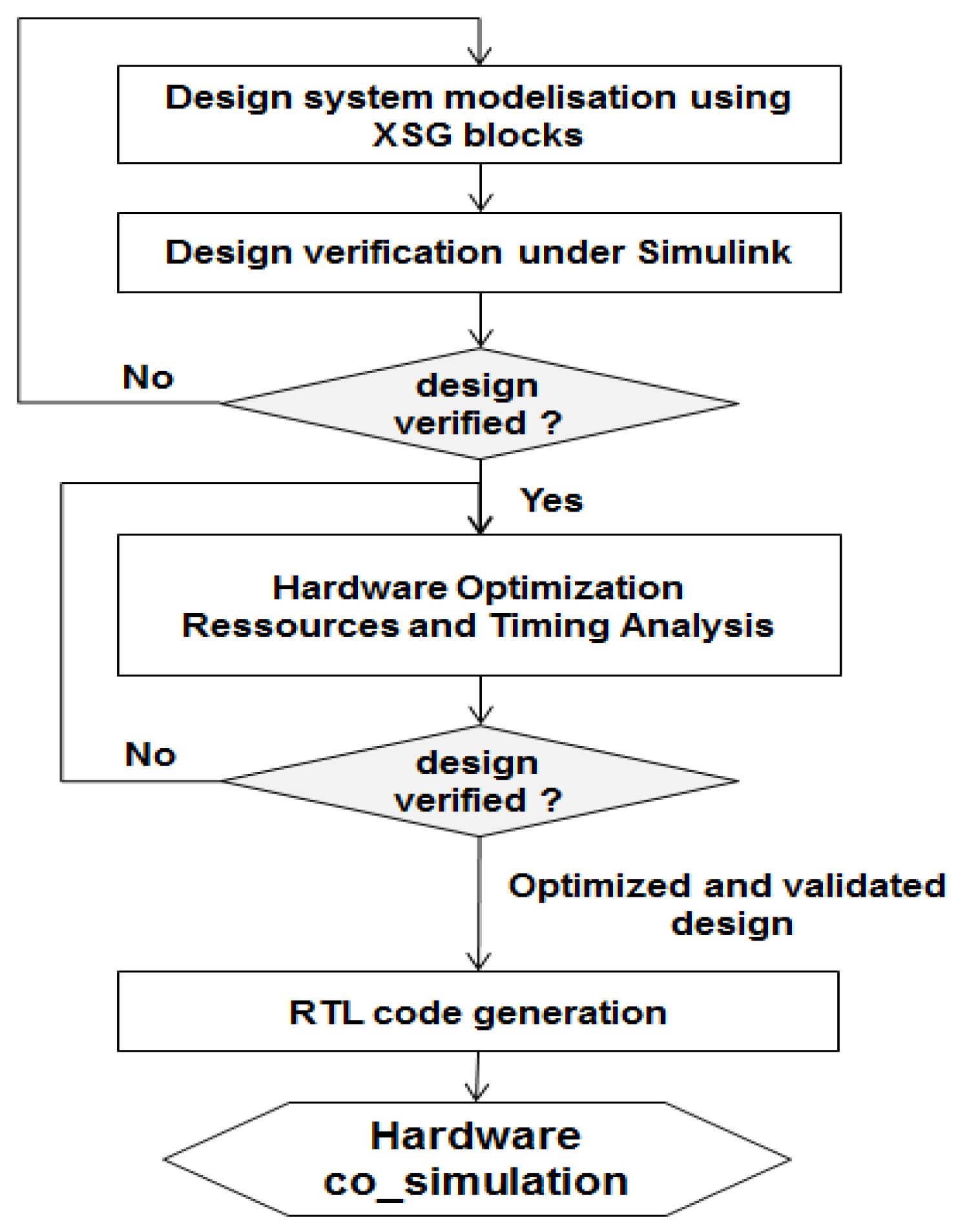
5.1. XSG Design Flow Diagram
5.2. Hardware Optimization
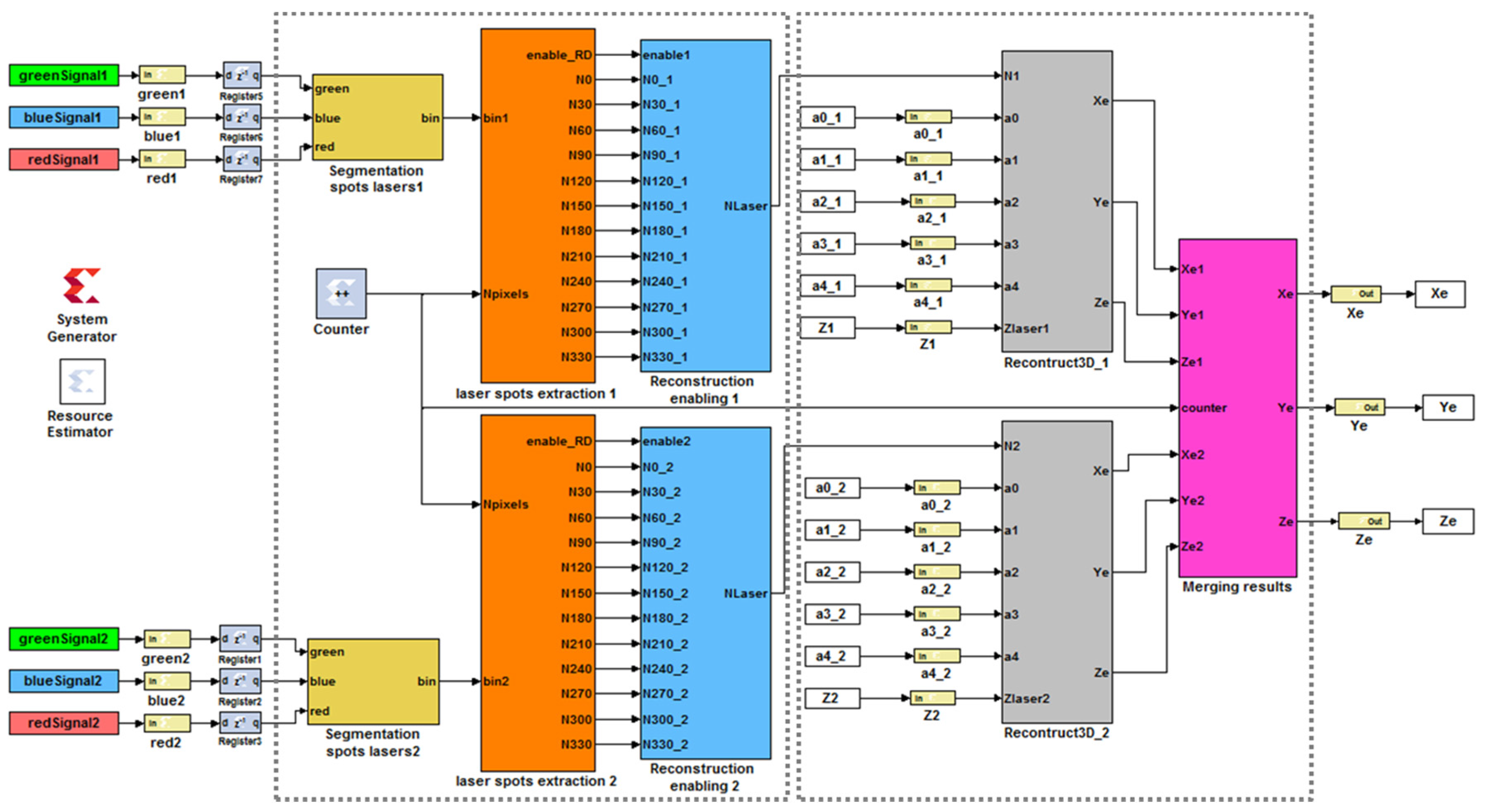
5.3. Hardware Architecture of the proposed 3D Shape Reconstruction System
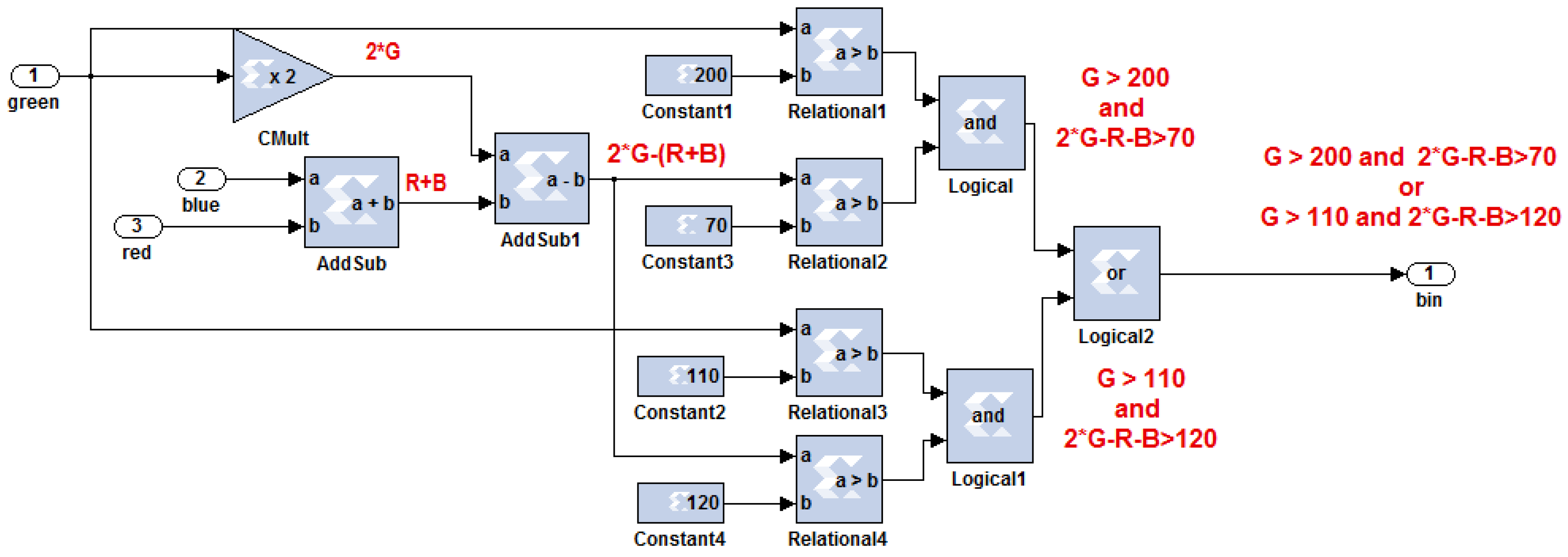
5.3.1. Hardware Architecture of the Laser Spot Detection Algorithm
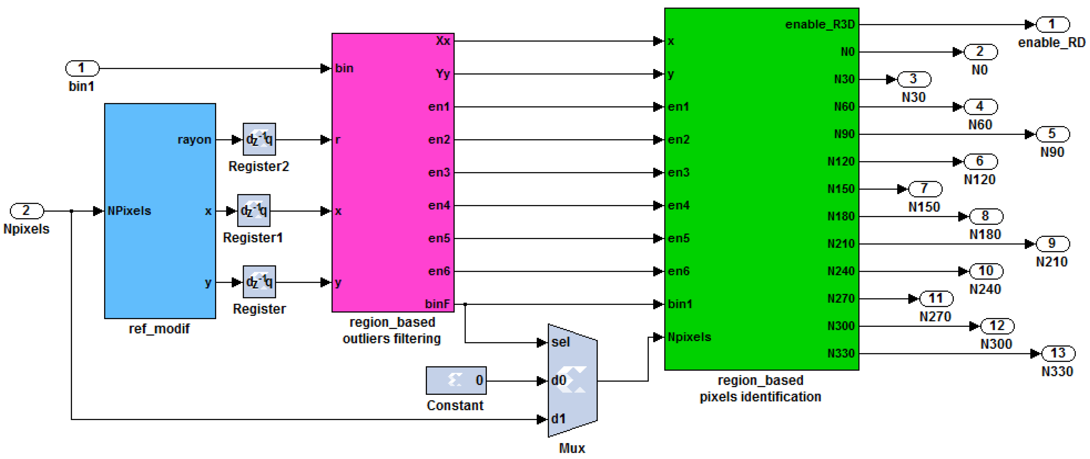
5.3.2. Hardware Architecture of the 3D Reconstruction Algorithm
- (1)
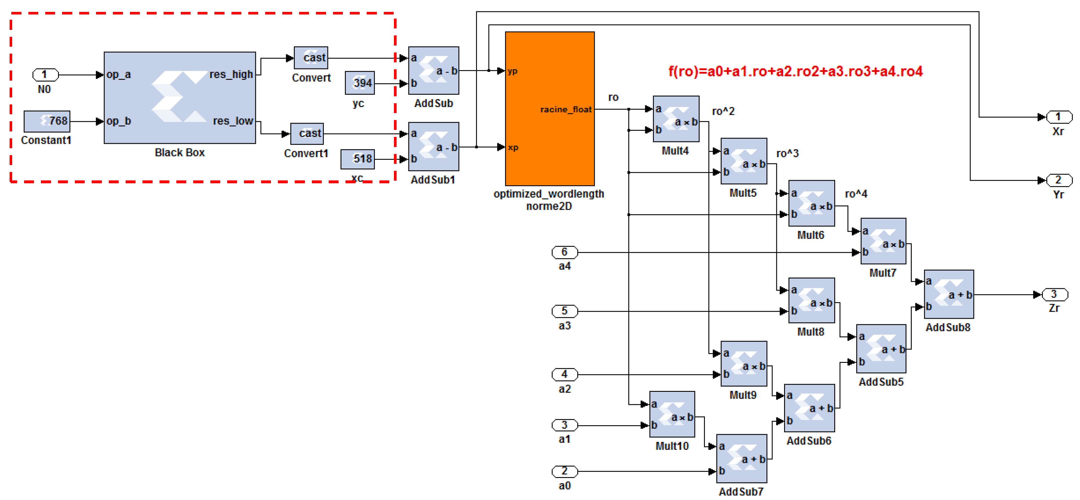
- Scaramuzza calibration function block;
- (2)
- Normalization block;
- (3)
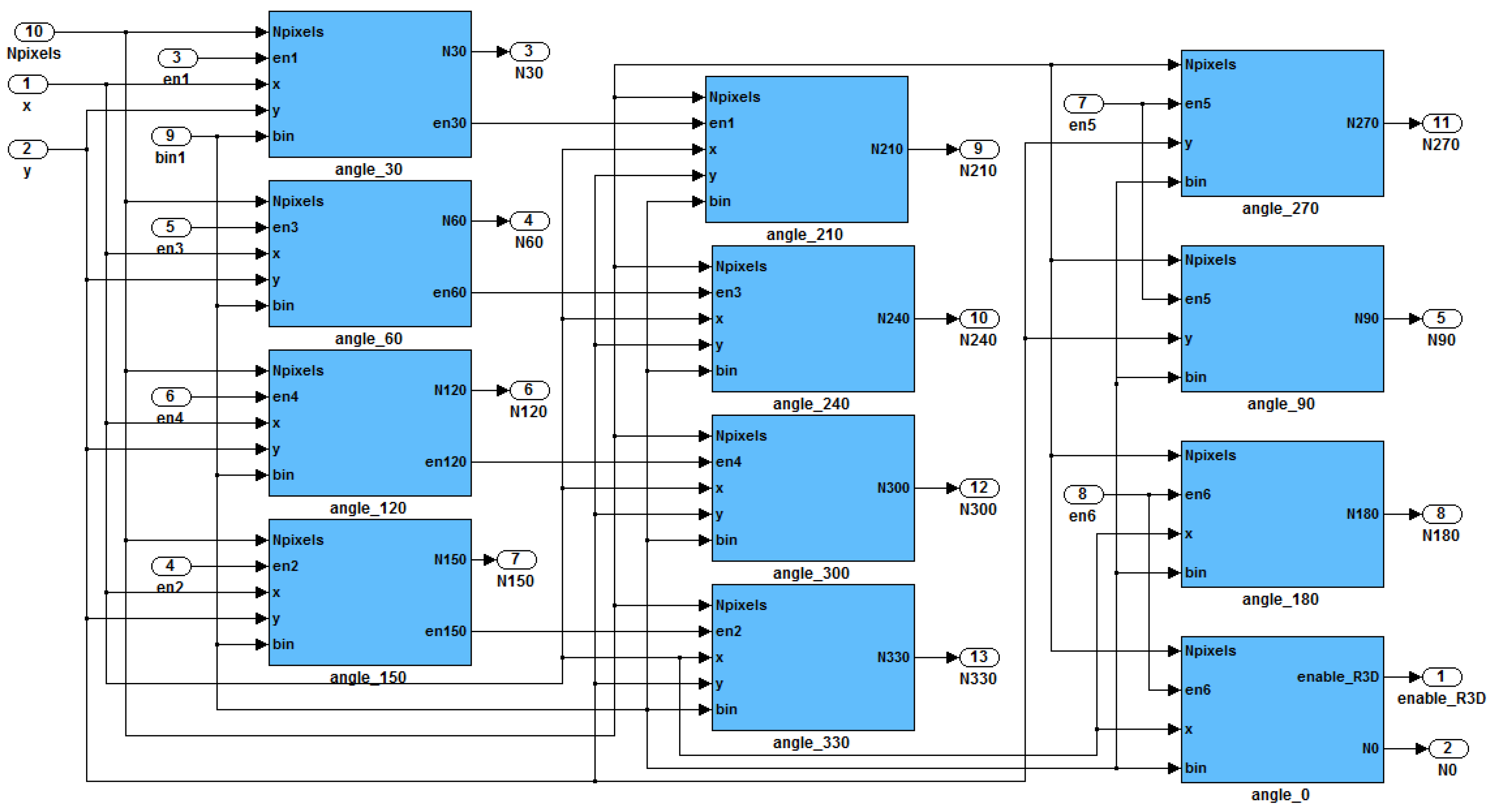
- Refraction angle estimation block;
- (4)
- Distance measurement and real point coordinates estimation block.
6. Experimentation and Performance Evaluation
6.1. Hardware Co_Simulation Results Comparison
6.2. System Performances Analysis and Discussion
- (1)
- Maximum throughput of 275 Mega-pixel per second
- (2)
- Pre-processing and laser spots extraction execution time = 2.86 ms
- (3)
- 3D reconstruction execution time = 0.00436 ms
- (4)
- Total execution time considering the pipeline = 2.86 ms
7. Conclusions
Acknowledgments
Author Contributions
Conflicts of Interest
References
- Jin, S.; Cho, J.; Pham, X.D.; Lee, K.M.; Park, S.-K.; Kim, M. FPGA design and implementation of a real-time stereo vision system. IEEE Trans. Circuits Sys. Video Technol. 2010, 20, 15–26. [Google Scholar]
- Hadjitheophanous, S.; Ttofis, C.; Georghiades, A.S.; Theocharides, T. Towards hardware stereoscopic 3D reconstruction a real-time FPGA computation of the disparity map. In Proceedings of the Design, Automation and Test in Europe Conference and Exhibition, Leuven, Belgium, 8–12 March 2010; pp. 1743–1748.
- Calonder, M.; Lepetit, V.; Fua, P. Keypoint signatures for fast learning and recognition. In Proceedings of the 10th European Conference on Computer Vision, Marseille, France, 12–18 October 2008; pp. 58–71.
- Zerr, B.; Stage, B. Three-dimensional reconstruction of underwater objects from a sequence of sonar images. In Proceedings of the 3rd IEEE International Conference on Image Processing, Lausanne, Switzerland, 16–19 September 2010; pp. 927–930.
- Johnson-Roberson, M.; Pizarro, O.; Williams, S.B.; Mahon, I. Generation and visualization of large-scale three-dimensional reconstructions from underwater robotic surveys. J. Field Rob. 2010, 27, 21–51. [Google Scholar]
- Gokhale, R.; Kumar, R. Analysis of three dimensional object reconstruction method for underwater images. Inter. J. Sci.Technol. Res. 2013, 2, 85–88. [Google Scholar]
- Meline, A.; Triboulet, J.; Jouvencel, B. Comparative study of two 3D reconstruction methods for underwater archaeology. In Proceedings of the IEEE/RSJ International Conference on Intelligent Robots and Systems, Vilamoura-Algarve, Portugal, 7–12 October 2012; pp. 740–745.
- Ladha, S.N.; Smith-Miles, K.; Chandran, S. Multi-user natural interaction with sensor on activity. In Proceedings of the 1st IEEE Workshop on User-Centered Computer Vision, Tampa, FL, USA, 16–18 October 2013; pp. 25–30.
- Kirstein, C.; Muller, H.; Heinrich, M. Interaction with a projection screen using a camera-tracked laser pointer. In Proceedings of the 1998 Conference on MultiMedia Modeling, Washington, DC, USA, 12–15 October 1998; pp. 191–192.
- Ahlborn, B.; Thompson, D.; Kreylos, O.; Hamann, B.; Staadt, O.G. A practical system for laser pointer interaction on large displays. In Proceedings of the International Symposium on Virtual Reality Software and Technology, New York, NY, USA, 7–9 November 2005; pp. 106–109.
- Brown, M.S.; Wong, W.K.H. Laser pointer interaction for camera-registered multi projector displays. In Proceedings of the IEEE International Conference on Image Processing, Barcelona, Spain, 14–17 September 2003; pp. 913–916.
- Davis, J.; Chen, X. Lumipoint: Multi-user laser-based interaction on large tiled displays. Displays 2002, 23. [Google Scholar] [CrossRef]
- Latoschik, M.E.; Bomberg, E. Augmenting a laser pointer with a diffraction grating for monoscopic 6DOF detection. Virtual Reality 2006, 4. [Google Scholar] [CrossRef]
- Oh, J.Y.; Stuerzlinger, W. Laser pointers as collaborative pointing devices. In Proceedings of the Graphics Interface Conference (GI’02), Calgary, Canada, 17–24 May 2002; pp. 141–149.
- Olsen, D.R.; Nielsen, T. Laser pointer interaction. In Proceedings of the SIGCHI Conference on Human Factors in Computing Systems, Seattle, Washington, USA, 31 March–5 April 2001; pp. 17–22.
- Kim, N.W.; Lee, S.J.; Lee, B.G.; Lee, J.J. Vision based laser pointer interaction for flexible screens. In Proceedings of the 12th International Conference on Human-Computer Interaction: Interaction Platforms and Techniques (HCII’07), Beijing, China, 22–27 July 2007; pp. 845–853.
- Meško, M.; Toth, Š. Laser spot detection. J. Inf. Control Manage. Syst. 2013, 11, 35–42. [Google Scholar]
- Chavez, F.; Olague, F.; Fernández, J.; Alcalá-Fdez, R.; Alcalá, F.; Herrera, G. Genetic tuning of a laser pointer environment control device system for handicapped people with fuzzy systems. In Proceedings of the IEEE International Conference on Fuzzy Systems (FUZZ), Barcelona, Spain, 18–23 July, 2010; pp. 1–8.
- Hogue, A.; German, A.; Jenk, M. Underwater environment reconstruction using stereo and inertial data. In Proceedings of the IEEE International Conference on Systems, Man and Cybernetics, Montréal, Canada, 7–10 October 2007; pp. 2372–2377.
- Brahim, N.; Gueriot, D.; Daniely, S.; Solaiman, B. 3D reconstruction of underwater scenes using image sequences from acoustic camera. In Proceedings of the Oceans IEEE Sydney, Sydney, NSW, Australia, 24–27 May 2010; pp. 1–8.
- Canny, J. A computational approach to edge detection. IEEE Trans. Pattern Anal. Mach. Intell. 1986, 8, 679–698. [Google Scholar]
- Gurol, O.C.; Oztürk, S.; Acar, B.; Sankur, B.; Guney, M. Sparse disparity map estimation on stereo images. In Proceedings of the 20th Signal Processing and Communications Applications Conference (SIU), Mugla, Turkey, 18–20 Apirl 2012; pp. 1–4.
- Deguchi, K.; Noami, J.; Hontani, H. 3D fundus shape reconstruction and display from stereo fundus images. In Proceedings of the 15th International Conference on Pattern Recognition, Barcelona, Spain, 3–7 September 2000; pp. 94–97.
- Moyung, T.J.; Fieguth, P.W. Incremental shape reconstruction using stereo image sequences. In Proceedings of the International Conference on Image Processing, Rochester, NY, USA, 22–25 September 2002; pp. 752–755.
- Dey, T.K.; Giesen, J.; Hudson, J. Delaunay based shape reconstruction from large data. In Proceedings of the IEEE Symposium on Parallel and Large-Data Visualization and Graphics, San Diego, CA, USA, 22–23 October 2001; pp. 19–146.
- Gibson, S.F. Constrained elastic surface nets: Generating smooth surfaces from binary segmented data. In Proceedings of the International Conference on Medical Image Computing and Computer-Assisted Intervention, Heidelberg, Germany, 11–13 October 1998; pp. 888–898.
- Lorensen, W.E.; Cline, H.E. Marching cubes: A high resolution 3D surface construction algorithm. In ACM Siggraph Comput. Graphics 1987, 21, 163–169. [Google Scholar]
- Hajebi, K.; Zelek, J.S. Structure from infrared stereo images. In Proceedings of the Canadian Conference on Computer and Robot Vision, Windsor, UK, 28–30 May 2008; pp. 105–112.
- McGlamery, B. Computer analysis and simulation of underwater camera system performance; Visibility Laboratory, University of California: San Diego, CA, USA, 1975. [Google Scholar]
- Jaffe, J.S. Computer modeling and the design of optimal underwater imaging systems. IEEE J. Oceanic Eng. 1990, 15, 101–111. [Google Scholar]
- Schechner, Y.Y.; Karpel, N. Clear underwater vision. In Proceedings of the IEEE Computer Society Conference in Computer Vision and Pattern Recognition (CVPR), Washington, DC, USA, 29 June–1 July 2004; pp. 536–543.
- Jordt-Sedlazeck, A.; Koch, R. Refractive calibration of underwater cameras. In Proceedings of the Computer Vision–ECCV 2012, Florence, Italy, 7–13 October 2012; pp. 846–859.
- Treibitz, T.; Schechner, Y.Y.; Kunz, C.; Singh, H. Flat refractive geometry. IEEE Trans. Pattern Anal. Mach. Intell. 2012, 34, 51–65. [Google Scholar]
- Kunz, C.; Singh, H. Hemispherical refraction and camera calibration in underwater vision. In Proceedings of the IEEE OCEANS, Quebec City, Canada, 15–18 September 2008; pp. 1–7.
- Sorensen, S.; Kolagunda, A.; Saponaro, P.; Kambhamettu, C. Refractive stereo ray tracing for reconstructing underwater structures. In Proceedings of the IEEE International Conference on Image Processing (ICIP), Quebec City, Canada, 27–30 September 2015; pp. 1712–1716.
- Carlo, S.Di.; Prinetto, P.; Rolfo, D.; Sansonne, N.; Trotta, P. A novel algorithm and hardware architecture for fast video-based shape reconstruction of space debris. J. Adv. Sign. Proces. 2014, 147, 1–19. [Google Scholar]
- Bräuer-Burchardt, C.; Heinze, M.; Schmidt, I.; Kühmstedt, P.; Notni, G. Underwater 3D surface measurement using fringe projection based scanning devices. Sensors 2015, 16. [Google Scholar] [CrossRef]
- Moore, K.D.; Jaffe, J.S.; Ochoa, B.L. Development of a new underwater bathymetric laser imaging system: L-Bath. J. Atmos. Oceanic Technol. 2000, 17, 1106–1117. [Google Scholar] [CrossRef]
- Newman, P.; Sibley, G.; Smith, M.; Cummins, M.; Harrison, A.; Mei, C.; et al. Navigating, recognizing and describing urban spaces with vision and lasers. Inter. J. Rob. Res. 2009, 28, 1406–1433. [Google Scholar] [CrossRef]
- Creuze, V.; Jouvencel, B. Avoidance of underwater cliffs for autonomous underwater vehicles. In Proceedings of the IEEE/RSJ International Conference on Intelligent Robots and Systems, Lausanne, Switzerland, 30 September–4 October 2002; pp. 793–798.
- Niessner, Z.; Zollhöfer, M.; Izadi, S.; Stamminger, M. Real-time 3D reconstruction at scale using voxel hashing. ACM Trans. Graphics 2013, 32. [Google Scholar] [CrossRef]
- Ayoub, J.; Romain, O.; Granado, B.; Mhanna, Y. Accuracy amelioration of an integrated real-time 3d image sensor. In Proceedings of the Design & Architectures for Signal and Image Processing, Bruxelles, Belgium, 24–26 November 2008.
- Muljowidodo, K.; Rasyid, M.A.; SaptoAdi, N.; Budiyono, A. Vision based distance measurement system using single laser pointer design for underwater vehicle. Indian J. Mar. Sci. 2009, 38, 324–331. [Google Scholar]
- Massot-Campos, M.; Oliver-Codina, G.; Kemal, H.; Petillot, Y.; Bonin-Font, F. Structured light and stereo vision for underwater 3D reconstruction. In Proceedings of the OCEANS 2015-Genova, Genova, Italy, 18–21 May 2015; pp. 1–6.
- Scaramuzza, D.; Martinelli, A.; Siegwart, R.A. Toolbox for easily calibrating omnidirectional cameras. In Proceedings of the Intelligent Robots and Systems, Beijing, China, 9–15 October 2006; pp. 5695–5701.
- Fischler, M.A.; Bolles, R.C. Random sample consensus: A paradigm for model fitting with applicatlons to image analysis and automated cartography. Commun. ACM 1981, 24, 381–395. [Google Scholar] [CrossRef]
- Mailloux, J.-G. Prototypage rapide de la commande vectorielle sur FPGA à l’aide des outils SIMULINK - SYSTEM GENERATOR. Thesis report, Quebec University, Montreal, QC, Canada, 2008. [Google Scholar]
- Chaikalis, D.; Sgouros, N.P.; Maroulis, D. A real-time FPGA architecture for 3D reconstruction from integral images. J. Visual Commun.Image Represent. 2010, 21, 9–16. [Google Scholar] [CrossRef]
- Lee, S.; Yi, J.; Kim, J. Real-Time stereo vision on a reconfigurable system. Embedded Comput. Sys. Architectures Model. Simul. 2005, 3553, 299–307. [Google Scholar]
- Hariyama, M. FPGA implementation of a stereo matching processor based on window-parallel-and-pixel-parallel architecture. IEICE Trans. Fundam. Electron. Commun. Comput. Sci. 2005, E88-A, 3516–3522. [Google Scholar] [CrossRef]


| Ref. | [6] | [5] | [2] | [13] | [42] | [43] | Our algorithm |
|---|---|---|---|---|---|---|---|
| 3D capturing sensor | uncalibrated underwater images | stereo camera images using multi-beam sonar | perspective stereo image pairs | perspective camera + Laser pointers devices | CMOS camera+laser structured system | perspective camera + single laser pointer | Omnidirectional stereo images+structured laser system |
| Calibration | use given calibration information | underwater checkerboard corners detection | assume that cameras are calibrated and rectified | Homography on checkerboard measurement | checkerboard corners detection | manual distance measurements as reference | underwater checkerboard corners detection |
| Points of Interest detection | SURF detector | Harris corner detector | Sobel edge detector | Green segmentation | Median filter Erosion Region labeling | Segmentation Smoothing Dilating Center finding | Adaptive segmentation Epipolar geometry |
| Remove outliers | Epipolar geometry | Epipolar geometry | ✗ | ✗ | Median filter | Epipolar geometry | |
| 3D points | All stereo corresponding SURF points | All stereo corresponding Harris points | All edge points | Intensity Weighted Sum of laser clouds | Laser clouds center calculation | Laser position in axis center | Laser clouds gravity centers calculation |
| Matching | Euclidean distance between features vectors | Lucas–Kanade Tracker (epipolar lines) | Sum Absolute Difference | Grid Mapping Heuristic | Epipolar geometry (lines) | No matching needed | Epipolar geometry (search along a line) |
| 3D reconstruction | Triangulation (calibration informations) | Triangulation (midpoint method) | Triangulation (epipolar geometry) | Triangulation (system geometry) | Triangulation using off-line depth model | using reference measurement | Omnidirectional projection using system geometry |
| Underwater restitution | ✗ | underwater calibration parameters | ✗ | ✗ | ✗ | underwater reference measurement | underwater calibration parameters |
| Software implementation | ✓ | ✓ | ✗ | ✓ | ✗ | ✓ | ✗ |
| Hardware implementation | ✗ | ✗ | FPGA | ✗ | FPGA | ✗ | FPGA |
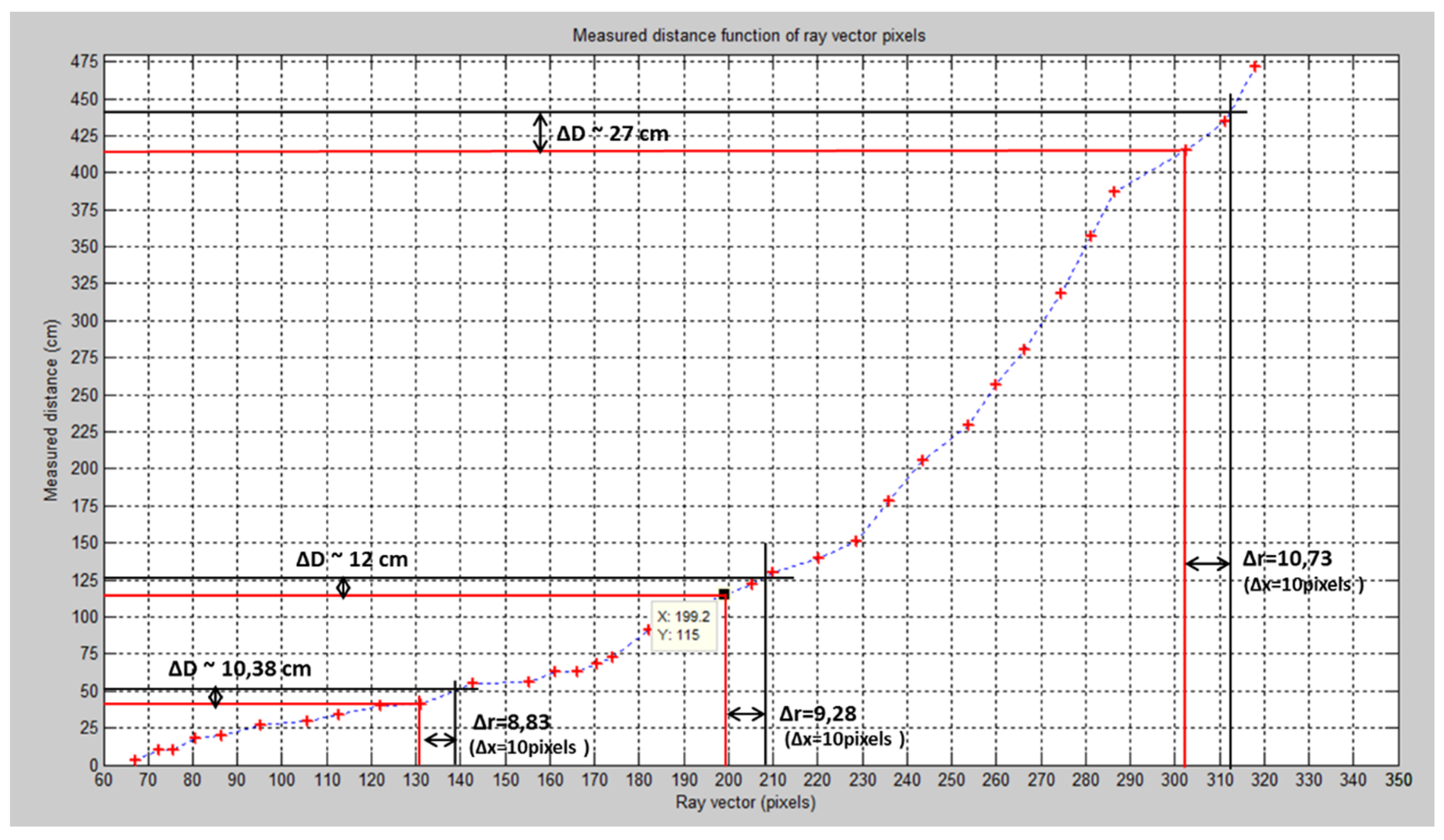
| Relative Measurements | Point 1 D = 40 cm | Point 2 D = 115 cm | Point 3 D = 415 cm | |
|---|---|---|---|---|
| ∆x = 1 pixel | ∆r | 0.88 | 0.93 | 0.97 |
| ∆D | 0.81 | 0.96 | 2 | |
| % | 1.02% | 1.01% | 1% | |
| ∆x = 10 pixels | ∆r | 8.83 | 9.28 | 10.73 |
| ∆D | 10.38 | 12 | 27 | |
| % | 1.26% | 1.10% | 1.07% | |
| Ref. | System Application | Sensing Device Performances | Implementation Target | Time Performances |
|---|---|---|---|---|
| [41] | Depth map 3D representation | Asus Xtion (30 Hz) Kinect camera (30 Hz) | Intel Core i7 3.4 GHz CPU | 21.8 ms/frame |
| [48] | Real-time 3D surface model reconstruction | Stereoscopic CCD cameras | Xilinx Virtex-5 FPGA (LX110T) | 170 MHz 15 fps |
| [36] | Video-based shape-from-shading reconstruction | Stereo digital cameras | Xilinx Virtex-4 FPGA (VLX 100) | 60 MHz 42 s/frame |
| [2] | Real-time 3D reconstruction of stereo images | Ten calibrated stereo image pairs | Virtex-2 Pro FPGA (XC2VP30) | 100 MHz 75 fps |
| [49] | Real-time 3D depth maps creation | Typical cameras 30 fps | Xilinx Virtex-2 (XC2V80) | 30 fps |
| [50] | Stereo matching for 3D image generation | 3 CCD cameras 320 × 320 pixels 33 MHz video rate | ALTERA FPGA (APEX20KE) | 86 MHz 0.19 ms/frame |
| Our system | Real-time 3D shape reconstruction from stereo images | Stereo catadioptric system 1024 × 768 pixels 66 MHz video rate | Xilinx Virtex-6 (VLX240T) | 275 MHz 30 fps 2.86 ms/frame |
© 2016 by the authors; licensee MDPI, Basel, Switzerland. This article is an open access article distributed under the terms and conditions of the Creative Commons Attribution (CC-BY) license (http://creativecommons.org/licenses/by/4.0/).
Share and Cite
Hmida, R.; Ben Abdelali, A.; Comby, F.; Lapierre, L.; Mtibaa, A.; Zapata, R. Hardware Implementation and Validation of 3D Underwater Shape Reconstruction Algorithm Using a Stereo-Catadioptric System. Appl. Sci. 2016, 6, 247. https://doi.org/10.3390/app6090247
Hmida R, Ben Abdelali A, Comby F, Lapierre L, Mtibaa A, Zapata R. Hardware Implementation and Validation of 3D Underwater Shape Reconstruction Algorithm Using a Stereo-Catadioptric System. Applied Sciences. 2016; 6(9):247. https://doi.org/10.3390/app6090247
Chicago/Turabian StyleHmida, Rihab, Abdessalem Ben Abdelali, Frédéric Comby, Lionel Lapierre, Abdellatif Mtibaa, and René Zapata. 2016. "Hardware Implementation and Validation of 3D Underwater Shape Reconstruction Algorithm Using a Stereo-Catadioptric System" Applied Sciences 6, no. 9: 247. https://doi.org/10.3390/app6090247