Article

Electrospinning Fabrication and Performance Evaluation of Polyacrylonitrile Nanofiber for Air Filter Applications

Department of Mechanical Engineering and High Safety Vehicle Core Technology Research Center, INJE University, 607 Eobang-dong, Gimhae-si, Gyongsangnam-do 621-749, Korea
*
Author to whom correspondence should be addressed.
Appl. Sci. 2016, 6(9), 235; https://doi.org/10.3390/app6090235
Submission received: 27 July 2016 / Revised: 8 August 2016 / Accepted: 10 August 2016 / Published: 23 August 2016
(This article belongs to the Section Energy Science and Technology)

Abstract

:
Nano materials possess unique mechanical, physical, and chemical properties. They are small, and have an ultrahigh surface area, making them suitable for air filter applications since air filtration is necessary to protect sensitive components from harmful particulates and gaseous contaminants. The electrospinning method has been recognized as an efficient technique for fabricating polymer nanofibers. In order to determine the optimum manufacturing conditions, the effects of several electrospinning process parameters on the diameter, orientation, and distribution of polyacrylonitrile (PAN) nanofiber are analyzed. To improve interlaminar fracture toughness and suppress the delamination in the form of laminated non-woven fibers by using a heat roller, the performances of filter efficiency and pressure drop achieved with the PAN nanofiber air filter are evaluated experimentally.

Graphical Abstract

1. Introduction

In many applications, air filters contribute to protect components which are sensitive to contaminants, such as carbon monoxide, sulfur containing compounds, salt aerosols, hydrocarbons, ammonia, and nitrogen oxides. As shown in the literature [1,2], the best method to deal with air contamination of an energy production system is by using an air filter [2]. It is well known that filters must be designed to be durable and effective, maintain a low pressure drop, have a long lifetime, be easy to handle, be low cost, have a small package space, and be flexible to each specific demand. Nanofibers are one of the unique materials which have many advantages applicable for manufacturing air filters in order to respond to specific requirements as listed above due to the high surface-to-volume ratio, low resistance, and enhanced filtration performance.
Recently, scientific techniques, along with nanotechnologies, have increased interest in methods capable of producing fibers that are produced from nanometers to micrometers [3]. Electrospinning is a manufacturing process that utilizes a different electric charge [3,4]. Polymers, ceramics, composite materials, a solution, or a molten material are able to produce fibers with a diameter from micrometers to nanometers with a relatively simple method [5]. Nanofibers produced by electrospinning have a high filtration efficiency for their very small diameters, large surface area per unit mass, and small pore size [6]. Additionally, due to the large porosity, the pressure drop that occurs is low when filtering impurities. Using these characteristics, submicron size particles or harmful gases can be removed. The nanofiber air filter can be used in various places, such as in semiconductor, clean room, dust collector, power generation, and precision machinery applications [7,8,9].
For the fabrication of polymer nanofibers, electrospinning has been recognized as an efficient technique. Electrospinning is achieved when a high voltage is applied to the water droplets hanging on the edge of the capillary. It has been known worldwide that the electrospinning method uses an electrostatic field and ejects to liquid jet from the syringe tip [10,11,12]. The hemispherical shape of the suspended droplet preserved in equilibrium at the end of the syringe tip may be distorted into a cone in the presence of an electric field. Surface tension is reduced with the electric charge distribution induced on the surface of the liquid, causing a distortion in the balance of the repulsive force. When the jet exceeds a critical voltage, a stable jet of liquid is ejected from the syringe tip. In the case of a low viscosity liquid, the jet is broken up into droplets as a result of the longitudinal Rayleigh instability caused by the surface tension. Conversely, for high viscosity liquids, the jet does not break up; however, it travels continuously to the collector plate. A transverse instability or splaying of the jet into two or more smaller jets is observed due to the radical charge repulsion [13]. This process is termed as electrospinning and it products the polymer fibers with a diameter in the nanoscale [14,15,16,17,18,19].
It is well known that polyacrylonitrile (PAN) materials have attracted much attention because of various excellent characteristics, such as thermal stability and tolerance to most solvents, atmosphere, bacteria, and photo irradiation, making them suitable for air filter applications. In this research, we conducted the electrospinning using a PAN polymer with a dimethyl formamide (DMF) solution to produce nanofibers, which can be potentially-applied cathode air filters. In addition, the PAN nanofiber air filter, which was fabricated by using the electrospinning method and laminated by non-woven fabric and PAN nanofiber through a heat roller, was experimentally analyzed for the filtration efficiency and pressure drop.
In order to produce the uniform formation of nanofibers, we investigated changing the electrospinning conditions, such as the flow rate, voltage, and distance between the syringe tip and collector plate. In the case of a high-viscosity solution, the polymer solution and high applied voltage produce the formation of fiber without beads and thinner fibers. The surface tension is driven toward the formation of the beads and, thus, the reduced surface tension will favor the formation of the fibers without beads [20]. In addition, changing the polymer concentration may change the solution viscosity [21]. Furthermore, the droplet formation is due to the collapse of the capillary jet emitted by the surface tension [22]. For the polymer solution, the pattern of collapse of the capillary is dramatically changed. Instead of breaking rapidly, the filament and spraying droplets are stabilized and a stable bead structure is formed. The reason is that the dissolved polymer is transformed by the extensible flow of the jet into the solid fiber [23,24,25].
As the viscosity of the solution is increased, the beads and fiber diameter become larger and the shape of the beads also changes. When the applied voltage is increased, decreased surface tension makes the beads become smaller or gradually disappear, while the diameter of fibers also becomes smaller. Neutralization of the charge carried by the jet supports the formation of beads since the tension in the fibers depends on the net charge repulsion and the interaction of the net charge with the electric field. In this research, we analyzed the formation of the PAN nanofiber, thickness of the fiber, and the presence or absence of the beads by scanning electron microscope (SEM) images. This is the foundation to produce the PAN nanofiber under optimum conditions.
In the manufacturing process, we used a commercially available heat roller to manufacture the PAN nanofiber air filter, via a lamination process using heat and pressure to seal the nanofiber paper between the plastic sheets. Normally, the heat, pressure, and adhesive are applied to bend the sheet of paper, but we used only the heat and pressure without the adhesive. The commercial heat rollers used in this research allow for controlled temperature and lamination speeds. The heat roller is composed of a pair of heated, rubber-covered rollers mounted on fixed axes, and a pair of stationary heated bars. The temperature signal for temperature control is provided by a surface thermocouple sliding on the metal core of one of the two heated rolls [26]. The PAN nanofiber air filter was manufactured in the lamination process. The non-woven fabric and nanofiber was manufactured by using heat and pressure applied to heat roller, respectively. PAN nanofiber air filter A was manufactured in a two-layer structure (non-woven fabric, PAN nanofiber), and PAN nanofiber air filter B was manufactured as a sandwich structure (non-woven fabric, PAN nanofiber, non-woven fabric).
As mentioned above, in order to produce the uniform formation of nanofiber materials used for air filter applications to protect sensitive components from harmful particulates and gaseous contaminants, we performed the electrospinning method as an efficient technique for fabricating polymer nanofibers. This research focused on optimizing the electrospinning conditions and manufacturing process to find the best method to manufacture nanofibers. The optimum conditions for manufacturing the PAN nanofiber were as follows: the solution sample including 1 g PAN and 10 mL DMF were physically stirred at a voltage of 10 kV, with a distance of 28 cm between the syringe tip and collector plate, and a flow rate of 0.3 mL/h. The experimental tests of fabricated nanofiber air filters in the laboratory, according to the British standard and the European standard, showed that they satisfied the criteria of high efficiency air filters.

2. Experimental Procedure

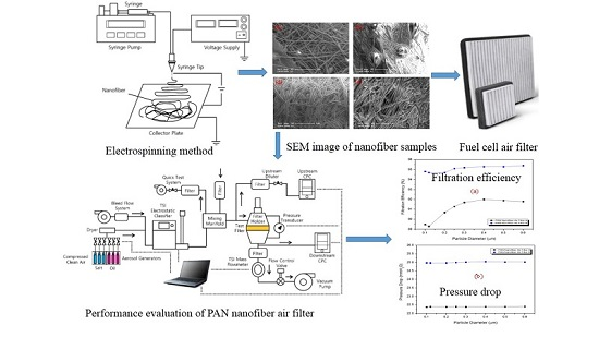
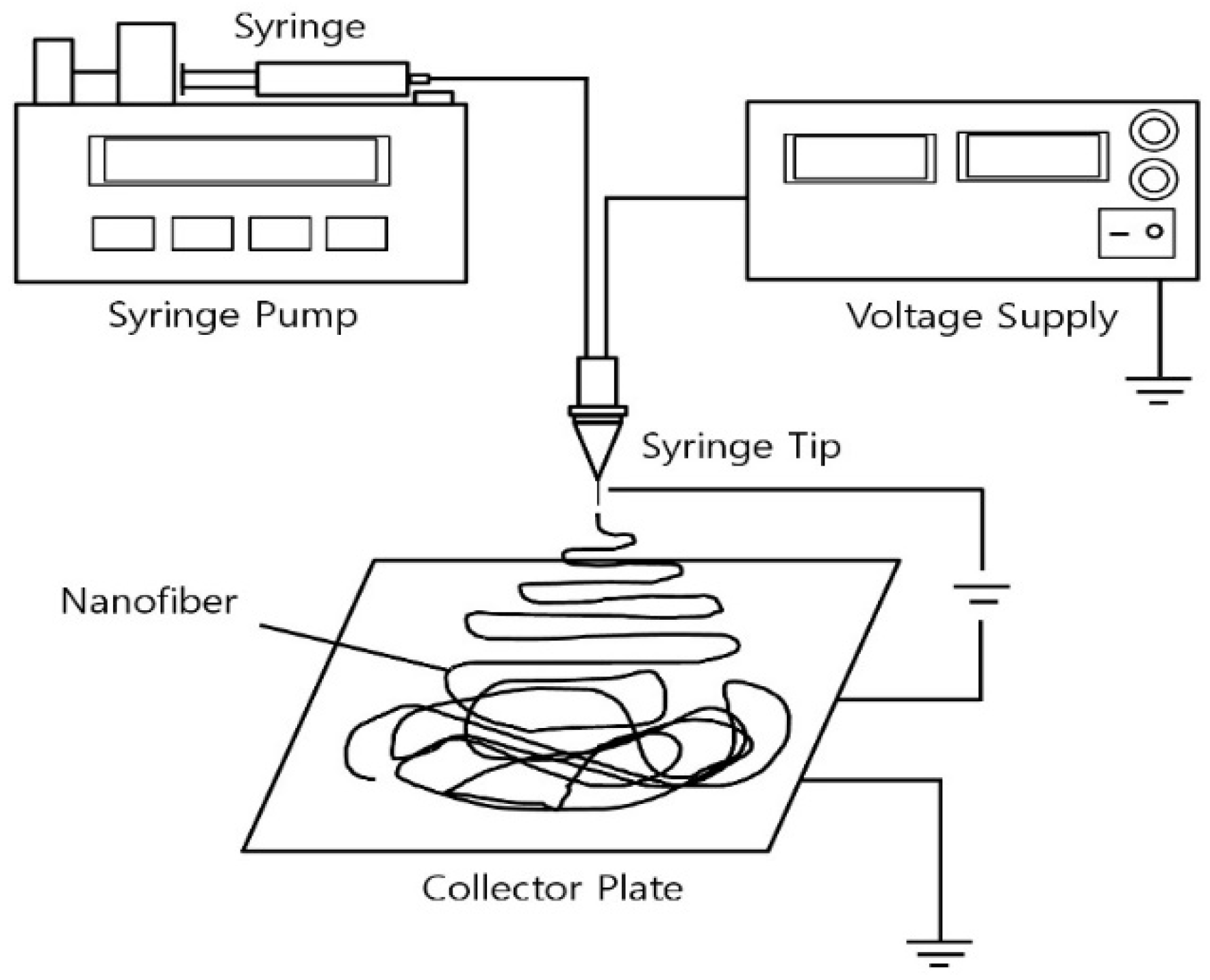
2.1. Electrospinning Process

The most common and easy approach to make nanofibers is the electrospinning method, as listed in the literature. In recent years, the electrospinning technique has attracted much attention as a capable method to produce fibers with nanoscale diameters. Figure 1 and Table 1 show the schematic diagram of the electrospinning device and PAN nanofiber manufacturing conditions for manufacturing nanofibers in this experiment, respectively. In this process, the polymer solution at the end of syringe tip is in the form of a hemispherical droplet. The standard electrospinning equipment consists of a high-voltage power supply, a metallic capillary, and a grounded collector as a counter electrode. Polymer solution is extruded from an orifice to form a small droplet in the presence of an electric field [27]. As mentioned above, when an electric field is applied, the charge or dipole orientation is induced on the surface of the air layer and the solution for the hemispherical droplet surface, mutual charge repulsion or dipole causes a force directly opposite of the surface tension. The electrically-charged solution jets are ejected from the orifice when the electrostatic force is larger than a threshold point. The feed rate can be adjusted, for example, with a syringe pump. The polymeric fluid tends to stretch out and form a continuous fiber until it reaches a grounded collector. Thus, the hemispherical surface of the fluid at the tip of syringe elongates to form a cone shape known as a Taylor cone. When the electric field reaches a critical value at which the repulsive electric force overcomes the surface tension force, a charged jet of the solution is ejected from the syringe tip. In this study, the electrospinning was carried out using the Nano NC Company NNC-ESP100 (Salamander Pumps, Sunderland, Britain). The solutions used in the electrospinning experiments were prepared using PAN polymer, DMF solvent purchased from Sigma Aldrich and Macron Company (Seoul, South Korea). The solution sample including 1 g PAN and 10 mL DMF was physically stirred for 24 h (350 rpm, 40 °C) in order to produce a PAN polymer solution, the viscosity of the prepared solution was also measured by using a viscometer. The PAN polymer solution was spun at a flow rate of 0.3 mL/h, the distance between the syringe tip and the collector plate was kept at 4 cm for five hours. The high-voltage NNC-ESP100 power supply was used to provide a voltage of 10 kV.

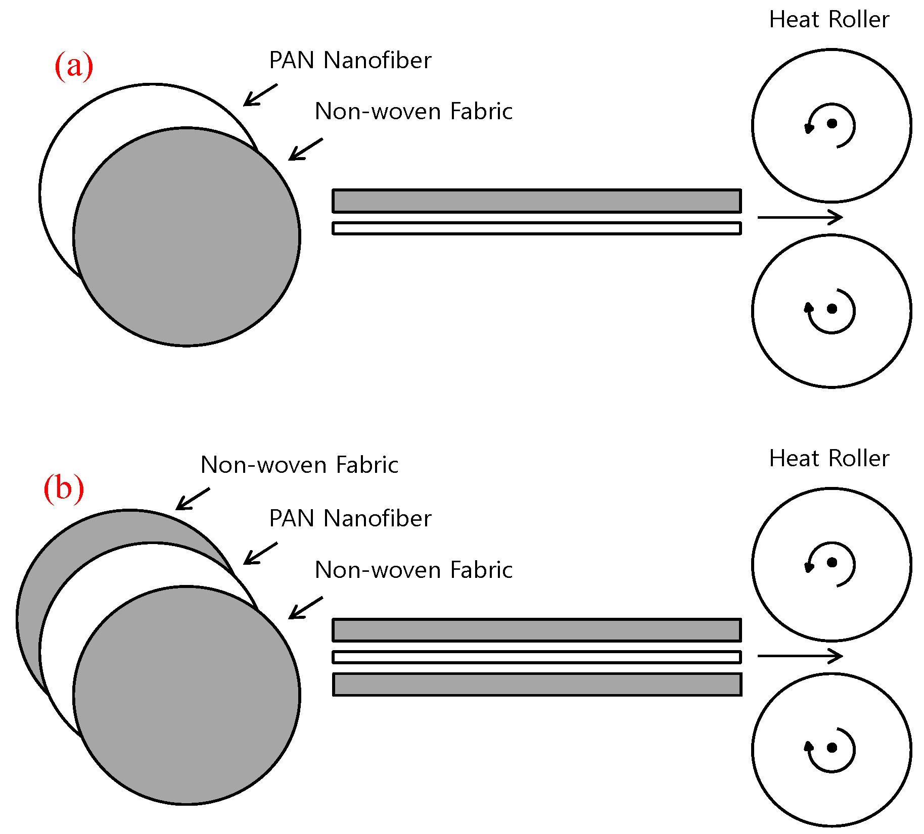
2.2. Heat Roller Process

Figure 2 and Table 2 show the schematic diagram of the manufactured PAN nanofiber air filter and PAN nanofiber manufacturing conditions using the heat roller (Dongwoo Heat Treating Co., Seoul, South Korea). The heat roller device is capable of controlling temperatures and lamination speeds. It is composed of three pairs of heated bars, and heat is transferred simultaneously to both sides of the rotating roller. The lamination processing method of the heat roller, a method of utilizing pressure and heat rollers by passing the material for air filter products between rollers to rotate, is cheap and simple compared to other processes. The PAN nanofiber air filter was manufactured in the lamination process, the non-woven fabric and nanofiber were manufactured via heat roller by, respectively, using heat and pressure. PAN nanofiber air filter A was manufactured by placing the one non-woven fabric and nanofiber in the heat roller, PAN nanofiber air filter B was manufactured by placing the one non-woven fabric between the two nanofibers in the heat roller. In this process of the experiment, the temperature on both sides was 140 °C, extrusion velocity was 3.3 mm/s, and it was repeated to laminate four times.

3. Result and Discussion

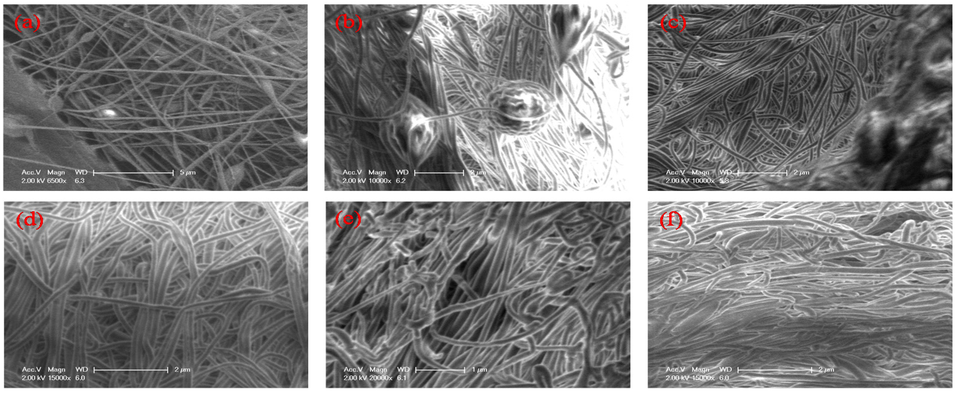
3.1. Manufacture of PAN Nanofiber

In order to produce the uniform formation of nanofibers by electrospinning, the main factors, such as solution viscosity, flow rate, voltage, and distance between the syringe tip and the collector plate, should be controlled [28]. The concentration and applied voltage are important, directly affecting nanofiber quality. The polymer solution is radiated when the concentration is low and the applied voltage is high because resistance of the electric force overcomes the surface tension in the syringe tip, but beads are created on the fiber surface. On the other hand, the polymer solution is not radiated when the applied voltage is low since resistance to the electric force does not overcome the surface tension [29]. In this study, to mix 1 g PAN with 10 mL DMF, they were stirred for 24 hours and radiated under the same conditions listed in Table 3. Each radiated for 15 minutes to control the flow rate, voltage, syringe tip, and collector plate in the electrospinning procedure and the collective fiber phenomenon was imaged using a scanning electron microscope (JEOL, Akishima, Japan).
The Figure 3 shows the SEM images of PAN nanofiber samples corresponding to the various controlled conditions. The fiber has a stable form without beads. In addition, the diameter of the nanofiber is formed corresponding to a dimensional range of 200–300 nm. The optimum condition is a mix of 1 g PAN polymer, 10 mL DMF solution, voltage of 10 kV, 28 cm of distance between syringe tip and collector plate, and flow rate of 0.3 mL/h.
In the cases of samples (a) and (b), the flow rate was controlled; the Taylor cone was unstable, however, the collection of the fibers was realized. This was not complete nanofiber and did not create beads. In the cases of samples (c) and (d), they were applied a voltage, and the diameters of the fibers were in the range of 100–200 nm, but the Taylor cone was also unstable, and then the PAN + DMF solution resulted in the falling phenomenon from the end of the syringe tip to the collector plate. In addition, in the cases of samples (e) and (f), the syringe tip distance to the collector plate was controlled; as a result, the diameters of the fibers were small. When the distance of the collector plate and the syringe tip was too close, the fiber shape did not form. In addition, the diameters of the fibers were also not uniform.

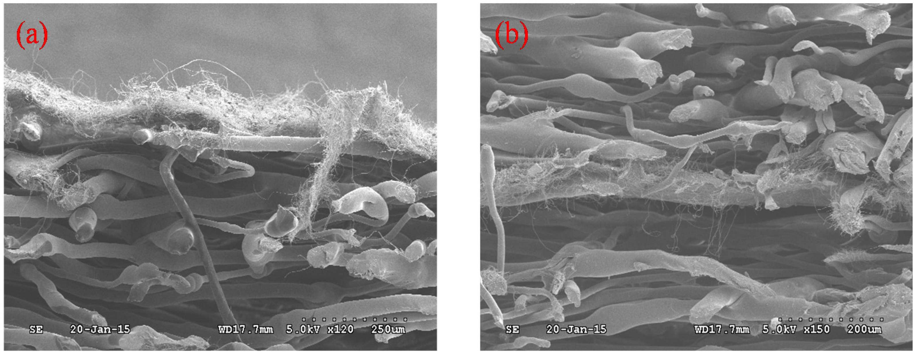
3.2. Layer of PAN Nanofiber Air Filter

Figure 4 shows the SEM images when using the heat roller to manufacture the PAN nanofiber air filter. PAN nanofiber air filter layers were sealed to 140 °C by using a heat roller, and the heat was transferred simultaneously to both sides of the rotating roller. The lamination velocity was adjusted to 3.3 mm/s and rotated repeatedly for four cycles. The PAN nanofiber air filters A and B were manufactured with layered manufacturing through pressure and thermosetting. PAN nanofiber air filter A had a structure where impurities with large particle diameters were removed, and impurities with small particle diameters were filtered in the pre-treatment. PAN nanofiber air filter B was improved both in efficiency and durability.

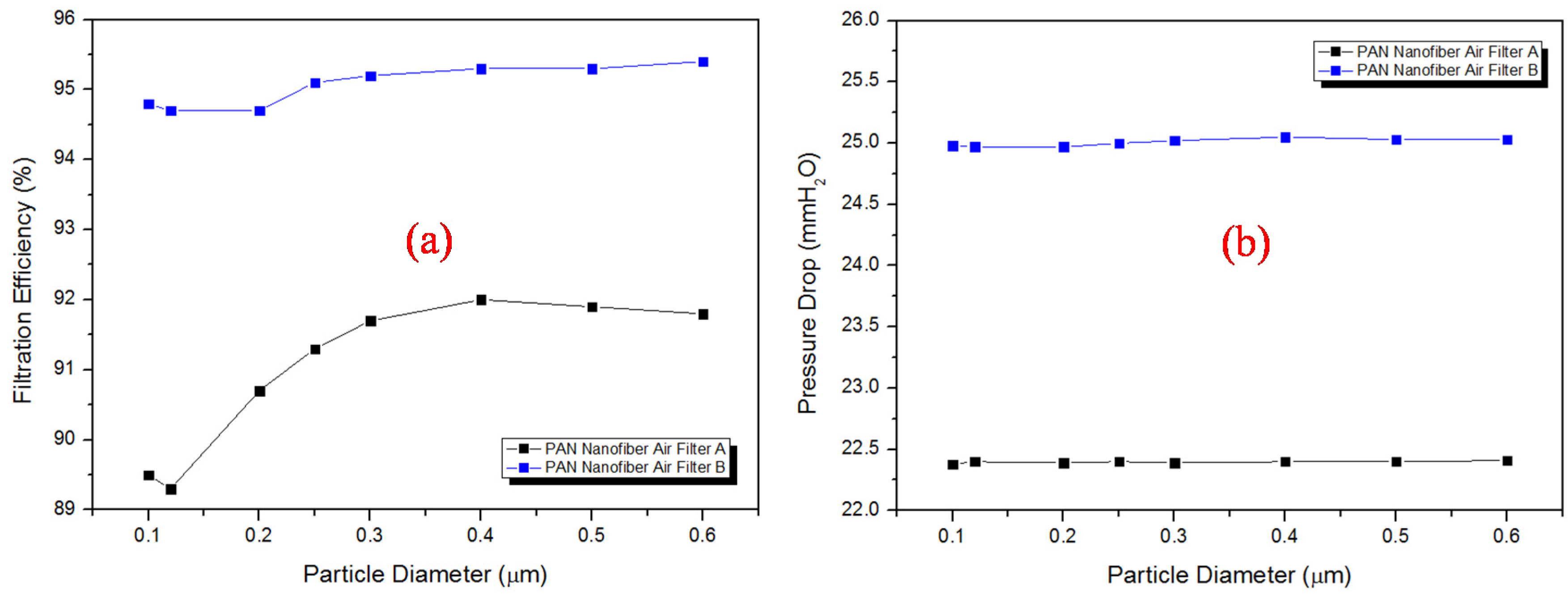
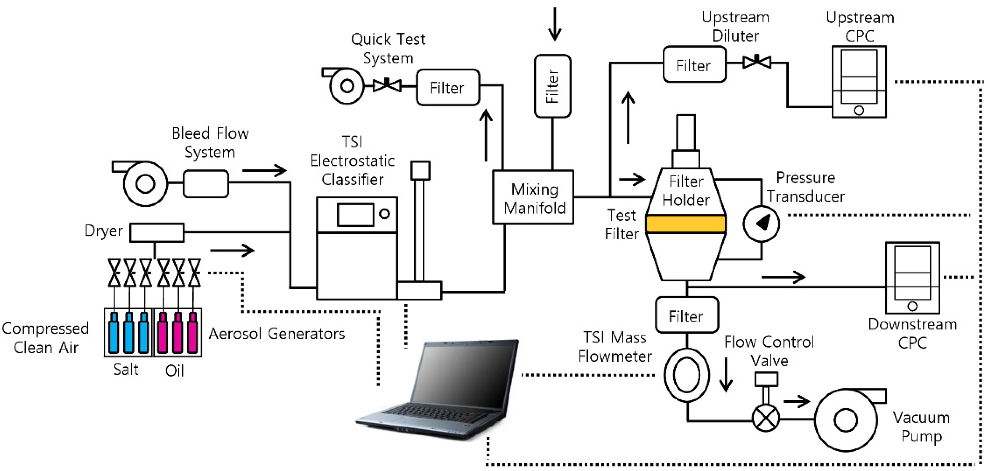
3.3. Performance Evaluation of The PAN Nanofiber Air Filters

Figure 5 shows a schematic diagram of the PAN nanofiber air filter efficiency and pressure drop performance evaluation apparatus. The filtration efficiency and pressure drop performance evaluation device were configured with the particle generation portion, the tester filter holder section, and detector. In this study, the performances of nanofiber air filter A and B were tested using the TSI-Fractional 3160 equipment (TSI Inc., Shoreview, MN, USA) at the Korean Institute of Industrial Technology (KITECH). The test conditions were controlled at a temperature of 25 °C, humidity of 40%, flow rate of 32 L/min, face velocity of 5.3 cm/s, and the test particle size range was 0.1–0.6 μm. With a diameter of 15 cm, PAN nanofiber air filters A and B were placed, respectively, at the test filter holder section. The particle counter and the micro-manometer, which are installed upstream and downstream, respectively, were measured the filtration efficiency and pressure drop. The test method was carried out in accordance with British standards and the European standard (BS EN 1822-3), and performance test conditions are shown in Table 4.
Figure 6 shows the filtration efficiency and pressure drop of PAN nanofiber air filter A and B. The manufactured PAN nanofiber air filter A had a measured filtration efficiency of 91 ± 0.1% and pressure drop of 22 ± 0.1 mmH2O for 0.3 μm particle diameter size. The manufactured PAN nanofiber air filter B had a measured filtration efficiency of 95 ± 0.1% and pressure drop of 25 ± 0.1 mmH2O for 0.3 μm particle diameter size. The PAN nanofiber air filter B increased the pressure drop, and it had structural stability and a high filtration efficiency. Additionally, it satisfied the criteria of high efficiency air filters EPA E11 (collection efficiency of 95% or more, transmittance less than 5%) based on the performance evaluation of the British standards and European Standard BS EN 1822-3 [30].

4. Conclusions

In this study, non-woven fabrics were laminated with PAN nanofiber by using the heat roller in order to manufacture the PAN nanofibers air filters. The optimum conditions for manufacturing the PAN nanofiber were as follows: the solution sample, including 1 g PAN and 10 mL DMF, was physically stirred at a voltage of 10 kV, with a distance of 28 cm between the syringe tip and collector plate, and a flow rate of 0.3 mL/h. Consequently, the emitted PAN nanofibers were not formed as beads, and they also maintained a stable shape without a tangling phenomenon between the fibers. The diameter of the fibers was in the range of 200–300 nm. The heat roller device used to produce the PAN nanofiber air filter was capable of the required temperature and lamination velocity. In addition, it was composed of three pairs of heated bars, and the heat was transferred simultaneously to both sides of the rotating rollers. The PAN nanofiber air filters were manufactured via the lamination process. The non-woven fabric and nanofibers are manufactured by using heat and pressure applied to the heat rollers, respectively, at 140 °C, with a 3.3 mm/s lamination velocity, and rotated repeatedly for four cycles. The experiment in this research with manufactured PAN nanofiber air filters was conducted at KITECH.
In the performance test of the air filter of fabricated PAN nanofiber, NaCl particles with a diameter of 0.3 μm, flow rate of 32 L/min, and face velocity of 5.3 cm/s, PAN nanofiber air filter A obtained a measured filtration efficiency of 91% and pressure drop of 22 mmH2O. PAN nanofiber air filter B obtained a measured filtration efficiency of 95% and pressure drop of 25 mmH2O.

Acknowledgments

This work was partly supported by the 2016 Inje University research grant and partly supported by the Basic Science Research Program through the National Research Foundation of Korea (NRF) funded by the Ministry of Education (No. 2015R1D1A1A02060006).

Author Contributions

Experimental design was by N.D.V. and H.-M.K., fieldwork was by N.D.V., statistical analyses were H.-M.K., and writing was by N.D.V. and H.-M.K. All authors discussed the results and commented on the manuscript.

Conflicts of Interest

The authors declare no conflict of interest.

References

  1. Daniel, M.K.; Donald, R.C.; Wenhua, H.Z.; Kenneth, C.W.; Nelms, R.M.; Bruce, J.T. Fuel cell cathode air filters: Methodologies for design and optimization. J. Power Sources 2007, 168, 391–399. [Google Scholar]
  2. Jon, M.M.; Paul, L.A.; Lakeman, J.B.; Gary, O.M. The effects of battlefield contaminants on PEMFC performance. J. Power Sources 2000, 85, 254–260. [Google Scholar]
  3. Cloupeau, M.; Prunet, F.B. Electrostatic spraying of liquid: Main functioning modes. J. Electrostat. 1990, 25, 165–184. [Google Scholar] [CrossRef]
  4. Christian, B.; Benjamin, S.H.; Benjamin, C. Nanofibrous materials and their applications. Ann. Rev. Mater. Res. 2006, 36, 333–368. [Google Scholar]
  5. Audrey, F.; Ioannis, S.C. Polymer nanofibers assembled by electrospinning. Curr. Opi. Colloid In. Sci. 2003, 8, 64–75. [Google Scholar]
  6. Jaeger, R.; Bergshoef, M.M.; Cristina, M.I.B.; Holger, S.; Vansco, G.J. Electrospinning of ultra-thin polymer fibers. Macromol. Symp. 1998, 127, 141–150. [Google Scholar] [CrossRef]
  7. Gibson, P.; Schreuder, G.H.; Pentheny, C. Electrospinning technology: Direct application of tailorable ultrathin membrane. J. Coated Fabrics 1998, 28, 63–72. [Google Scholar]
  8. Jong, S.K.; Reneker, D.H. Mechanical properties of composites using ultrafine electrospun fibers. Polym. Compos. 1999, 20, 124–131. [Google Scholar]
  9. Shin, Y.M.; Hohman, M.M.; Brener, M.P.; Rutledge, G.C. Electrospinning: A whipping fluid jet generates submicron polymer fibers. Appl. Phys. Lett. 2001, 78, 1149–1151. [Google Scholar] [CrossRef]
  10. Reneker, D.H.; Chun, I.S. Nanometre diameter fibers of polymer, produced by electrospinning. Nanotechnology 1996, 7, 216–223. [Google Scholar] [CrossRef]
  11. Tayler, G. Disintegration of Water drops in an electric field. P. Roy. Soc. Lond. A Mat. 1964, 280, 383–397. [Google Scholar] [CrossRef]
  12. Doshi, J.; Renerker, D.H. Electrospinning process and application of electrospun fibers. J. Electrostat. 1995, 35, 151–160. [Google Scholar] [CrossRef]
  13. Spivak, A.F.; Dzenis, Y.A. Asymptotic decay of radius of a weakly conductive viscous jet in an external electric field. Appl. Phys. Lett. 1998, 73, 3067–3069. [Google Scholar] [CrossRef]
  14. Shin, Y.M.; Hohman, M.M.; Brenner, M.P.; Rutledge, G.C. Experimental characterization of electrospinning: The electrically forced jet and instabilities. Polymer 2001, 42, 9955–9967. [Google Scholar] [CrossRef]
  15. Hendricks, C.D.; Schneider, J.M. Stability of a conducting droplet under the influence of surface tension and electrostatic force. Am. J. Phys. 1963, 31, 450–453. [Google Scholar] [CrossRef]
  16. Rayleigh, L. On the equilibrium of liquid conducting masses charged with electricity. Philos. Mag. A 1882, 14, 184–186. [Google Scholar] [CrossRef]
  17. Inculet, I.I.; Fischer, J.K. Electrostatic aerial spraying. IEEE Trans. Ind. Appl. 1989, 25, 558–562. [Google Scholar] [CrossRef]
  18. Deitzel, J.M.; Kleinmeyer, J.; Harris, D.; Beck, T.N.C. The effect of processing variables on morphology of electrospun nanofibers and textiles. Polymer 2001, 42, 261–272. [Google Scholar] [CrossRef]
  19. Copriani, E.; Zanetti, M.; Bracco, P.; Brunella, V.; Luda, M.P.; Costa, L. Crosslinking and carbonization processes in PAN films and nanofibers. Polym. Degrad. Stabil. 2016, 123, 178–188. [Google Scholar] [CrossRef]
  20. Fong, H.; Chun, I.; Renerker, D.H. Beaded nanofibers formed during electrospinning. Polymer 1999, 40, 4585–4592. [Google Scholar] [CrossRef]
  21. Saeed, A.; Syed, M.M.; Isa, M.T.; Abhilash, M.B.; Hamed, H. Experimental investigation of the effect of different process variables on the viscosity of sulfonated polyacrylamide copolymers. J. Petrol. Explor. Prod. Technol. 2016, 1, 1–15. [Google Scholar]
  22. Shimasaki, S.; Taniguchi, S. Formation of uniformly sized metal droplets from a capillary jet by electromagnetic force. Appl. Math. Modell. 2011, 35, 1571–1580. [Google Scholar] [CrossRef]
  23. Huang, Z.M.; Zhang, Y.Z.; Kotaki, M.; Ramakrishna, S. A review on polymer nanofibers by electrospinning and their application in nanocomposites. Compos. Sci. Technol. 2003, 63, 2223–2253. [Google Scholar]
  24. Fong, H.; Reneker, D.H. Elastomeric nanofibers of styrene-butadiene-styrene triblock copolymer. J. Polym. Sci. B 1999, 37, 3488–3493. [Google Scholar] [CrossRef]
  25. Tehron, S.A.; Zussman, E.; Yarin, A.L. Experimental investigation of the governing parameters in the electrospinning of polymer solutions. Polymer 2004, 45, 2017–2023. [Google Scholar] [CrossRef]
  26. Marco, F.C.; Ludimila, P. Sheet Splitting with a Heat Seal Lamination Technique. Available online: http://www.innventia.com/documents/rapporter/innventia%20report%2071.pdf (accessed on 18 July 2016).
  27. Garreau, A.; Duvail, J.L. Recent advances in optically active polymer-based nanowires and nanotubes. Adv. Opt. Mater. 2015, 2, 1122–1140. [Google Scholar] [CrossRef]
  28. Buchko, C.J.; Chen, L.C.; Shen, Y.; David, C.M. Processing and microstructural characterization of porous bipcompatible protein polymer thin films. Polymer 1999, 40, 7397–7407. [Google Scholar] [CrossRef]
  29. Entov, V.M.; Shmaryan, L.E. Numerical modeling of the capillary breakup of jets of polymeric liquids. Fluid Dyn. 1997, 32, 696–703. [Google Scholar]
  30. The New Series of BSEN 1822: 2010 Standard. Available online: http://www.tripleair-technology.com/TripleAir_Norm_EN.php (accessed on 18 July 2016).
Figure 1. Schematic diagram of the electrospinning method.
Applsci 06 00235 g001
Figure 2. Process setup of the lamination of heat roller: (a) PAN (polyacrylonitrile) nanofiber, non-woven fabric (2-layers structure); and (b) non-woven fabric, PAN nanofiber, non-woven fabric (three layer structure).
Applsci 06 00235 g002
Figure 3. SEM (scanning electron microscope) image of PAN nanofiber samples with different experimental conditions: (a) flow rate control of 0.1 mL/h; (b) flow rate control of 0.2 mL/h; (c) voltage control of 12 kV; (d) voltage control of 14 kV; (e) distance between syringe tip and collector plate of 23 cm; and (f) distance between syringe tip and collector plate of 18 cm.
Applsci 06 00235 g003
Figure 4. SEM images of (a) PAN nanofiber air filter A; and (b) PAN nanofiber air filter B.
Applsci 06 00235 g004
Figure 5. Schematic diagram for the performance evaluation of the PAN nanofiber air filters.
Applsci 06 00235 g005
Figure 6. Diagrams of (a) the filtration efficiency of PAN nanofiber air filter A and B; and (b) the pressure drop of the PAN nanofiber air filter A and B.
Applsci 06 00235 g006
Table 1. Experimental conditions to produce PAN (polyacrylonitrile) nanofibers by the electrospinning method.
PropertyName/Value
PolymerPolyacrylonitrile
SolventDimethylformamide
Molecular weight of repeat unit of PAN (g/mol)53.06
Solution viscosity (cSt)86
Flow rate (mL/h)0.3
Voltage (kV)10
Distance (cm)28
Injection hour (h)5
Table 2. Experimental conditions to produce PAN nanofiber air filter by the heat roller of SKY 325R6 model.
PropertyValue
Lamination Size (cm2)15
Lamination Velocity (mm/s)3.3
Lamination Temperature (°C)140
Measurement Times4
Table 3. Experimental conditions to manufacture PAN nanofiber samples by the electrospinning method.
SampleFlow Rate (mL/h)Voltage (kV)Distance (cm)
(a)0.11028
(b)0.21028
(c)0.31228
(d)0.31428
(e)0.31023
(f)0.31018
Table 4. Experimental conditions to evaluate PAN nanofiber air filter A, B performance by TSI-3160.
PropertyValue
Temperature (°C)25
Humidity (%)40
Filter size (cm2)15
Particle diameter (μm)0.1–0.6
Flow rate (l/min)32
Face velocity (cm/s)5.3

