Article

Hydration, Setting and Crack-Resistance Properties of Activated HVFACs at Early Stages

1
School of Mechanics and Engineering science, Zhengzhou University, Zhengzhou 450001, Henan, China
2
Construction Engineering Research Group, Faculty of Engineering Technology, Universiteit Hasselt, Diepenbeek B3590, Belgium
3
Urban Planning and Design Research Institute Co., Ltd., Zhengzhou 450044, Henan, China
4
School of Material Science and Engineering, Zhengzhou University, Zhengzhou 450001, Henan, China
*
Author to whom correspondence should be addressed.
Appl. Sci. 2016, 6(8), 224; https://doi.org/10.3390/app6080224
Submission received: 6 June 2016 / Revised: 27 July 2016 / Accepted: 29 July 2016 / Published: 10 August 2016

Abstract

:
In order to develop a simple and effective activation method of low calcium fly ash concrete (FAC) and to understand their basic properties, the present paper experimentally investigates the influences of the volume of fly ash (FA), the dosage of the activator (AC) and the water to binder ratio (w/b) on the hydration, setting times and the crack-resistance properties of activated FACs. Results verify that increasing FA can effectively reduce the hydration heat of the FA-cement system and increase the setting time of FACs, as well as indicate that FA can delay the occurrence of the initial crack and reduce the maximum width and total area of cracks in these concretes through a new quantitative test. The curing time of concrete affects the hydration heat of FA paste with/without AC. When the curing time of FAC increases, the decrease in amplitude of hydration heat reduces gradually. Additionally, it was found that the used ACs can effectively stimulate the activity of FA in Portland cement (PC) systems, which reduces their setting time slightly. However, high dosages of ACs also accelerate the development of early cracks in the FACs, as well. According to the study, the combined activator (10% CaO + 1.5% Na2SO4) was suggested as the most effective way to promote FA-PC concrete for obtaining acceptable properties at early stages. Besides, the existing calculation model for predicting the setting times of FACs was examined and modified to be more suitable to FACs activated by 10% CaO + 1.5% Na2SO4. The proposed model was verified and can evaluate the experimental results well.

Graphical Abstract

1. Introduction

With the development of the economy worldwide and the large production of fly ash (FA), as a by-product of various industries, such as thermal power stations, FA has been concerned as one of the potential alternatives of conventional cementitious materials (i.e., mainly Portland cement (PC)) or a part-replacement material of PC to propel eco-concrete since the 1930s. This is attributed to the fact that a number of researchers have attempted to solve/reduce to a large degree an unavoidable problem caused by the manufacturing of PC: its large amount of carbon dioxide (CO2) emission. As a construction material, the application of FA in concretes can improve the greenhouse effect of Earth’s atmosphere caused by the large amount of the emission of CO2 via reducing the utilization of PC in concretes and decrease natural environment pollution by decreasing the floating of FA in the air to decrease the danger to humans and other lives. Besides, it also has been reported that FA can improve the workability and durability properties of concrete and reduce the construction cost of reinforced concrete (RC) structures [1].
Fly ash has been studied sufficiently and used in concrete structures since the 1980s. In practical construction, FA is commonly used in RC structures with a cement replacement ratio of less than 30% of the volume or mass ratio till now. However, in 1986, high volume fly ash concrete (HVFAC) was first developed for mass concrete structures to obtain low heat generation and acceptable early strength [2]. Subsequently, numerous studies [3,4,5,6,7,8,9,10,11,12,13] focused on the properties of HVFAC, which was defined as an FAC whose 50% or greater than 50% of cement (volume ratio) was replaced by FA in the American Concrete Institute (ACI)-ACI 332R code [14]. Researchers [15,16,17] also suggested using HVFAC in other structural and pavement concretes considering its comprehensive properties and economy.
It is well known that mass concrete usually produces a great amount of heat caused mainly by the long-term and large volume hydration reaction of cementitious material. This results in that the internal temperature of concrete rises largely to form a temperature gradient compared to the external one, which then results in the inconsistent deformation/stress between external and internal concretes. The uneven temperature stress further leads to the development of internal and external crack devolvement, which subsequently affects the durability of these concrete structures. A number of studies [18,19,20,21] indicated that the use of FA in concrete is one of the most effective methods to reduce the hydration heat of mass concrete. However, it has been [22] also reported that fly ash cannot retard the hydration reactions of the cement, but can significantly reduce the heat release-peak temperature at early ages under semi-adiabatic conditions.
On the other hand, setting time is one of the key technology factors to determine the casting time and construction methods of RC structures. FA and ACs both will affect the initial and final setting times of concrete, in theory. At the same time, finding the ways to resist effectively and limit the crack development of concrete at the early stage is always one of the concerned research topics in concrete industries. It is attributed to the fact that the early unrecoverable plastic shrinkage cracks in concrete have a significant influence on the durability and other properties of concrete at later stages, e.g., they will result in the water moving from the surface to the internal concrete, and the tensile strength of concrete is lower than the concrete shrinkage stress. In addition, various chemical activators (AC) usually have been developed and applied to activate FA in PC concrete at the early age to improve the hydration action and obtain higher strength level. Based on previous studies, the ions of Cl, CO32− and NO3 could affect the alkaline solution of concrete to achieve the appropriate composition, which retards the setting of FAC subsequently [23]. In order to improve the early strength of concrete, sodium and potassium sulfate (SO42−) have been reported to activate FA in concrete [24]. Considering the possible effect of SiO2 on pozzolanic materials (e.g. volcanic ash), silicate also can be a potential activator for the FAC system [25]. Shi and Day [26] reported that Na2SO4 is a more efficient activator compared to CaCl2 in high calcium fly ash pastes. Via investigating the strength and microstructural properties, Lee et al. [27] pointed out that Na2SO4 is most effective in accelerating the consumption of Ca(OH)2 and increasing the amount of Ettringite in fly ash-cement pastes. Similar results have been reported by Zhang et al. [28]. Comparing to the grinding of FA, using Na2SO4 is more effective to promote the activity of FA [29]. However, until now, there has not been research which focused on the comprehensive early properties of activated FAC using Na2SO4, including hydration, setting and cracking. Therefore, to promote HVFAC in concrete industries, the studies on the effects of silicate, sulfate and calcium chloride ions in these early properties of FAC will be helpful to understand the activation of FA in a high volume FA-PC system well. Meanwhile, considering the effect of lime on low calcium FAC, the combined use of lime and Na2SO4 might be a potential way. The primary objectives of this study are to investigate the influences of the main variables on the hydration heat of the FA-PC system, the setting time and crack-resistance performance of FAC/HVFAC activated by several easily obtained chemical agents, Na2SO4 orNaSiO3 or CaCl2, as well as to examine and modify the existing model for predicting the setting time of FACs/HVFACs and to analyze the crack-resistance mechanism of FACs/HVFACs.

2. Materials and Methods

2.1. Materials, Mixtures and Test Procedures

2.1.1. Cementitious Materials

The cementitious materials used in this study include Portland cement (PC) and fly ash (Chinese standard, Type II, low-calcium level, Kaifeng Thermal Power Plant, Kaifeng, China), whose physical properties and chemical compositions are listed in Table 1, respectively. Fly ash (Type II) is a high quality fly ash with an ignition loss ratio between 5% and 8% and used usually in the preparation of pumping concrete, mass concrete, high sulfate resistance concrete, underwater engineering and grouting concrete in China. In this table, the water demand of cement or ash is the mass of water that can make cement/ash obtain a standard consistency.

2.1.2. Mix Proportion Details

All concrete mixes in this study used a reasonable accurate mass of Portland cement, fine and coarse aggregates, fly ash and water. Besides, to obtain a more reasonable workability of concrete, an admixture, FN-S2 high efficiency water reducing agent (liquid), was also added into the concrete. In all concrete specimens, natural crushed stones with a maximum size of 20 mm and natural river sands with a fineness modulus of 2.9 were used as the coarse and fine aggregate, respectively. The mix proportions of specimens are listed in Table 2 and Table 3. In this paper, Na2SiO3, CaCl2 and Na2SO4 were used in the concretes as the main activators to promote the reaction of fly ash in concrete. Meanwhile, little lime (CaO) (10% of cement mass) was used in all concrete specimens to obtain the appropriate strength of concrete. Because CaO is an effective activator to improve the production of Ca(OH)2 in the low calcium FAC [13], from here, the emphasis of the study focuses on the effect of Na2SiO3, CaCl2 and Na2SO4. The ACs in the present paper mean the three main activators. On the other hand, for the paste specimen, CaO was not used in this study. There are three specimens that were made for each concrete or paste. All of the tested specimens were cured in a moist chamber with a relative humidity of 90%–95% and a temperature of 18–22°C until the curing age of testing. In Table 2 and Table 3, the concrete specimen of CX-FAY-ACZ means that the FAC uses a concrete with the designed compressive strength of X MPa, an FA with a mass time of Y to cement and uses Z-type AC. The paste specimen FAx-ACy means an FAC paste was made with x% FA (mass of cement) and is activated by y% AC (by mass of binder).

2.1.3. Test Variables

In this study, to investigate the effect of the main variables on the hydration heat of the FA-PC system and the setting time and crack-resistance performance of FACs and HVFACs, specimens with multi-series variables were designed. In the study, HVFACs is defined as FAC using fly ash to replace at least 50% of the mass of cement.
Group 1 for the hydration heat test of the FA-PC system: mass of FA (0%–70% of cement) and dosage of AC (0%–2.0% of bind materials’ mass).
Group 2 for the setting time or strength test of FACs: mass of FA (0%–70% of cement), type and dosage of main AC (AC1: Na2SiO3; AC2: Na2SO4; AC3: CaCl2 with 0%–2.0% of the binding materials’ mass).
Group 3 for the crack-resistance test of FACs: mass of FA (0%–70% of cement), dosage of AC (0%–2.0% of the binding materials’ mass).

2.2. Instruments and Test Methods

2.2.1. Compressive Strength Test

Three cube specimens with a size of 100 mm × 100 mm × 100 mm were used for each mix proportion to test the compressive strength of concrete. All presented measured strengths of concrete are the mean values of the corresponding three specimens.

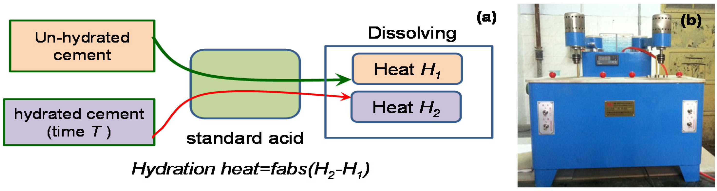
2.2.2. Hydration Heat
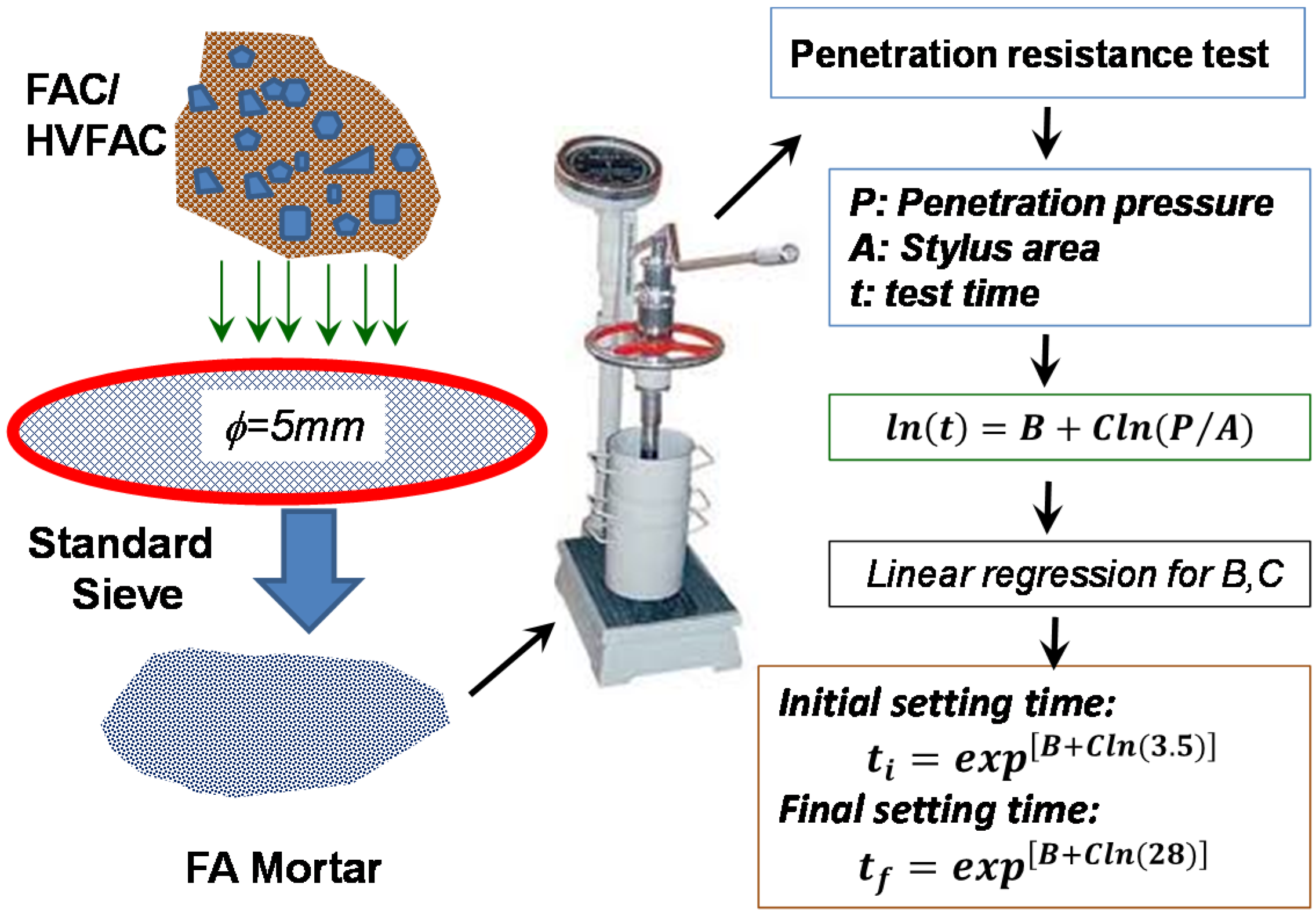
Based on the test methods to evaluate the hydration heat of cement (GB/T12959-2008) [30], the hydration heats of the FAC specimens are measured by a cement hydration heat detector (SHR-650II). The method is based on the thermo-chemical heat of hydration of Hess’ law, i.e., the heating effect of the chemical reaction is only associated with the initial state and final state of the tested system regardless of its reaction path. The ASTM C186 [31] uses a similar method to measure hydration heat. When the calorimeter temperature is kept at a constant level, the hydration heat of the tested cement under certain curing ages is defined as the difference between the measured solution heat, from the dissolving heat of un-hydrate cement (H1) and hydrated cement (H2) via using a certain concentration of standard acid. The method and instrument for testing hydration heat are illustrated in Figure 1.
To evaluate the hydration heat of various kinds of fly ash-cement systems under different conditions, the mix proportion details of FAC paste are listed in Table 3. The mass of FA in the binder of concretes/pastes changes from 0%–70% of PC, and the activation of FA-PC was completed by using chemical activator of Na2SO4 with 1.0, 1.5 or 2.0% of the binder materials’ mass.

2.2.3. Setting Time

In this paper, the instrument and process for measuring the setting time of concrete are shown in Figure 2, according to the Chinese standard test method, called the performance on ordinary fresh concrete, GB/T50080-2002 [32]. FAC/HVFAC specimens firstly were sifted form an FA paste by a standard sieve with the holes having a diameter of 5 mm, which was used for the subsequent test of penetration resistance. As shown in Figure 2, according to the test results, the penetration resistance pressure (P), stylus area (A) and test time (t) can be obtained, which can determine the initial setting time of FAC/HVFAC by linear regression and based on the theoretic penetration pressure of 3.5 MPa corresponding to the setting time of concrete. Similarly, the final setting time of specimens can be obtained when the theoretic penetration pressure was assumed as 28 MPa. To research the setting time, the concretes with water/binder (w/b) of 0.41 and different dosage of ACs and FA were used.

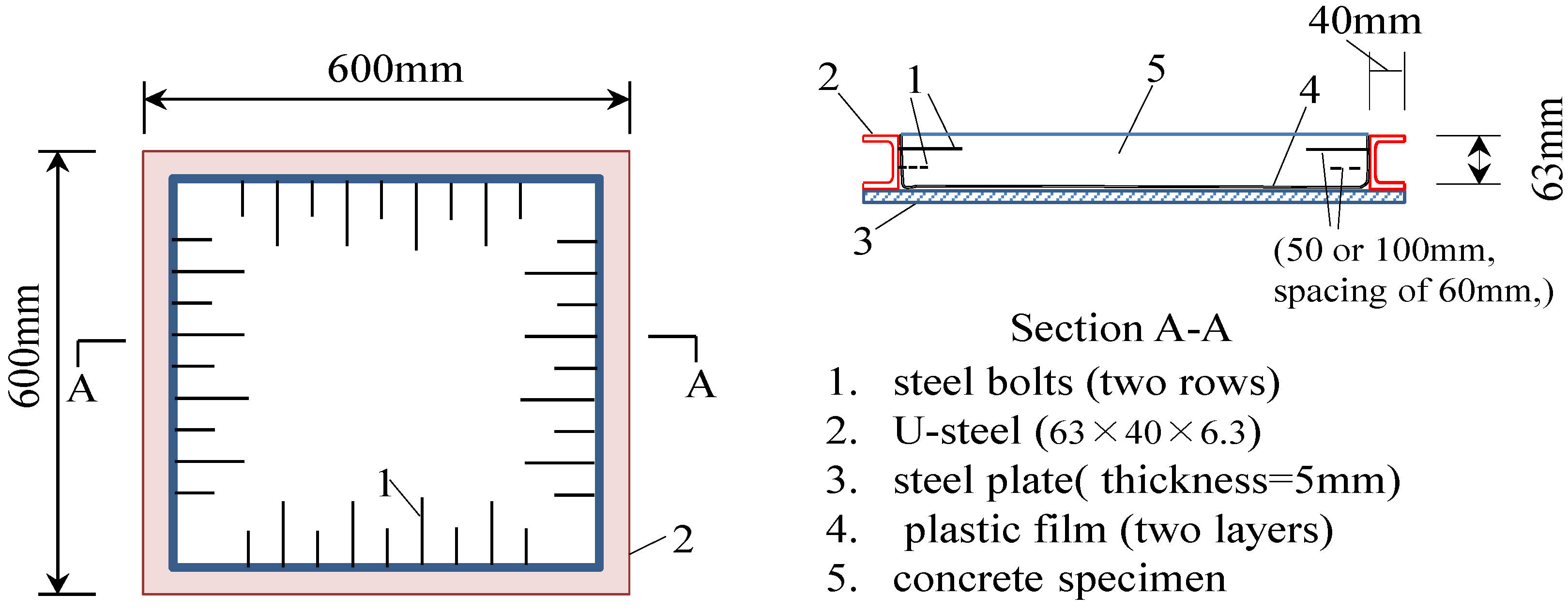
2.2.4. Crack-Resistance Test

As shown in Figure 3, in order to evaluate the crack-resistance of FACs, the instruments and standard testing methods for measuring the crack-resistance capacity of fiber-reinforced concrete (CECS 13-2009) [33] were used in this paper. In the ASTM test methods, ASTM C1581 [34] and C1579 [35] are similar methods; however, they focus on shrinkage cracking. The entire specimens in the crack resistance test are square concrete plates with a size of 600 mm × 600 mm × 63 mm and using coarse aggregates with a maximum size of 20 mm. To construct the concrete plates, a welded steel mold constituted of four U-steel with the size of 63 mm × 40 mm × 6.3 mm was set on a steel plate with a thickness of 5 mm, as shown in Figure 3. Along the internal side of each U-steel, two rows of steel bolts were fixed at a spacing of 60 mm. Before constructing the concrete plate, two layers of plastic films were laid on the bottom of the steel plate. The production of the concrete specimen needs to be plain to ensure that the concrete plate has no vertical deformation during its curing and measuring. For the measure process of crack development, firstly, all specimens were immediately dried by an electric fan at 30 min after they were constructed. The wind speed was kept as 5 m/s at the parallel direction of the specimen surface. These specimens were cured at a room with a room temperature of 18–22°C and a relative humidity of 55%–65%.
The time of initial crack (Tcr) was defined as when the first crack was visible by the naked eye at the specimen surface. The length and width of each crack were measured to evaluate the crack resistance capacity at 0.5 h, 1.5 h, 3.5 h and 27.5 h after the time of the initial crack, respectively. The widths of cracks were measured by reading a microscope with a division value of 0.005 mm. The area of the crack was defined as the multiplication of the length and width of each crack.

3. Experimental Results and Observation

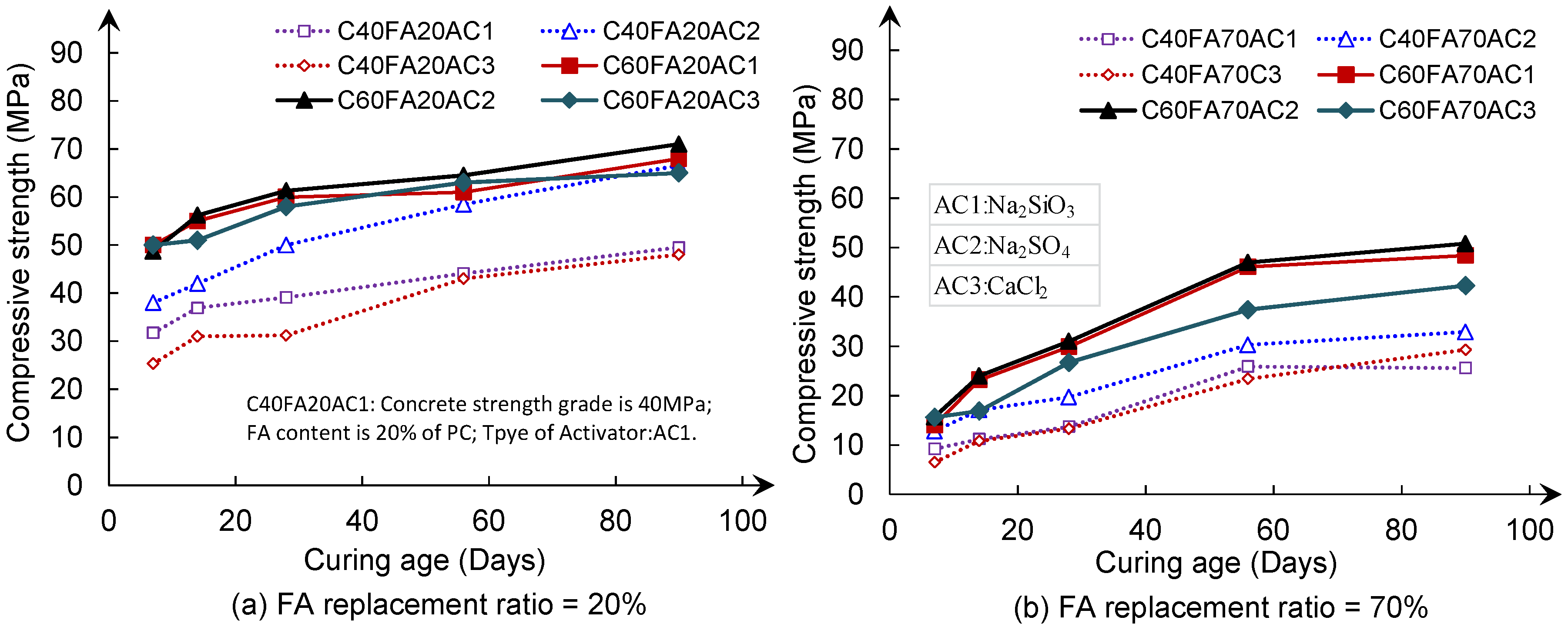
3.1. Compressive Strength
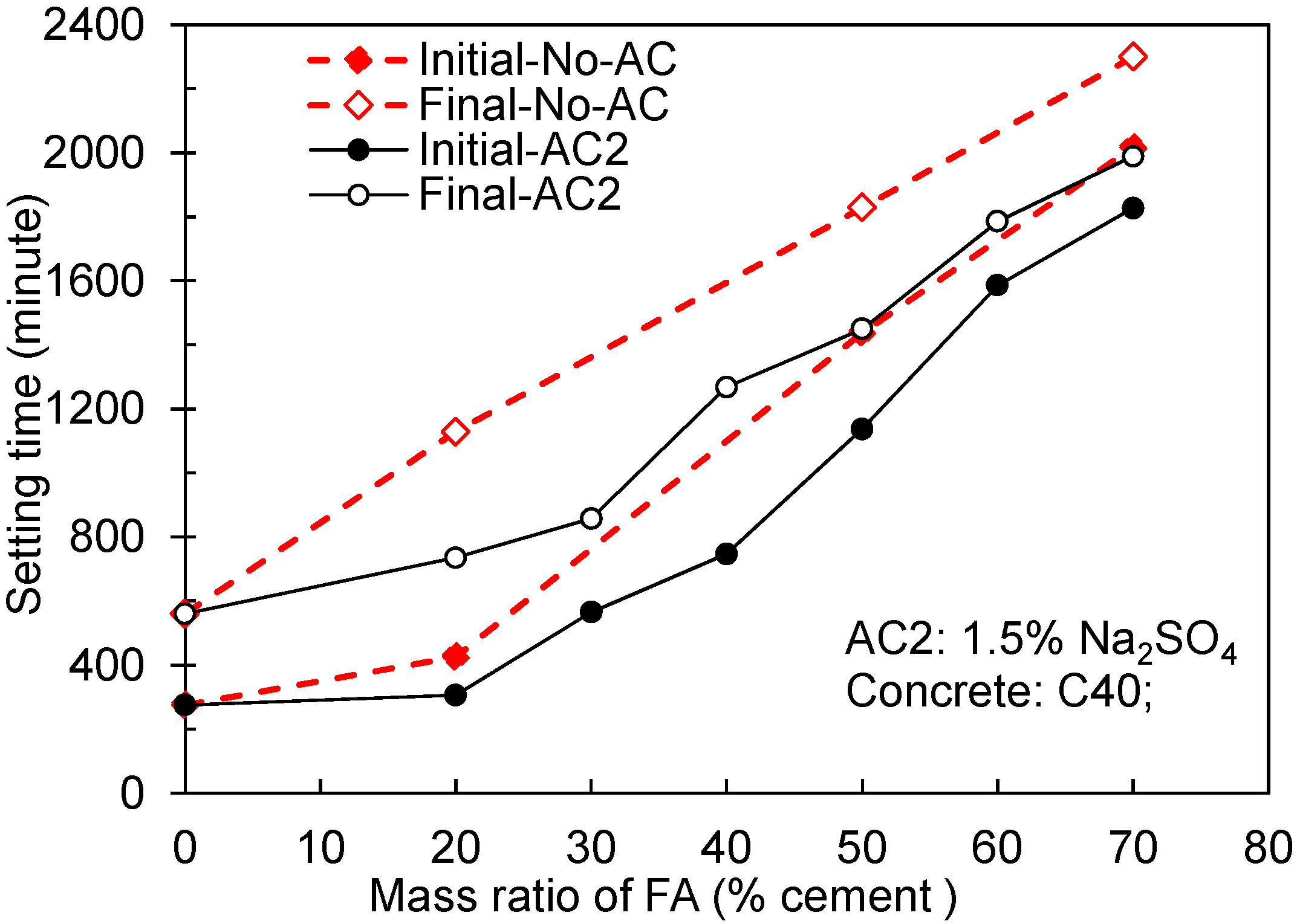
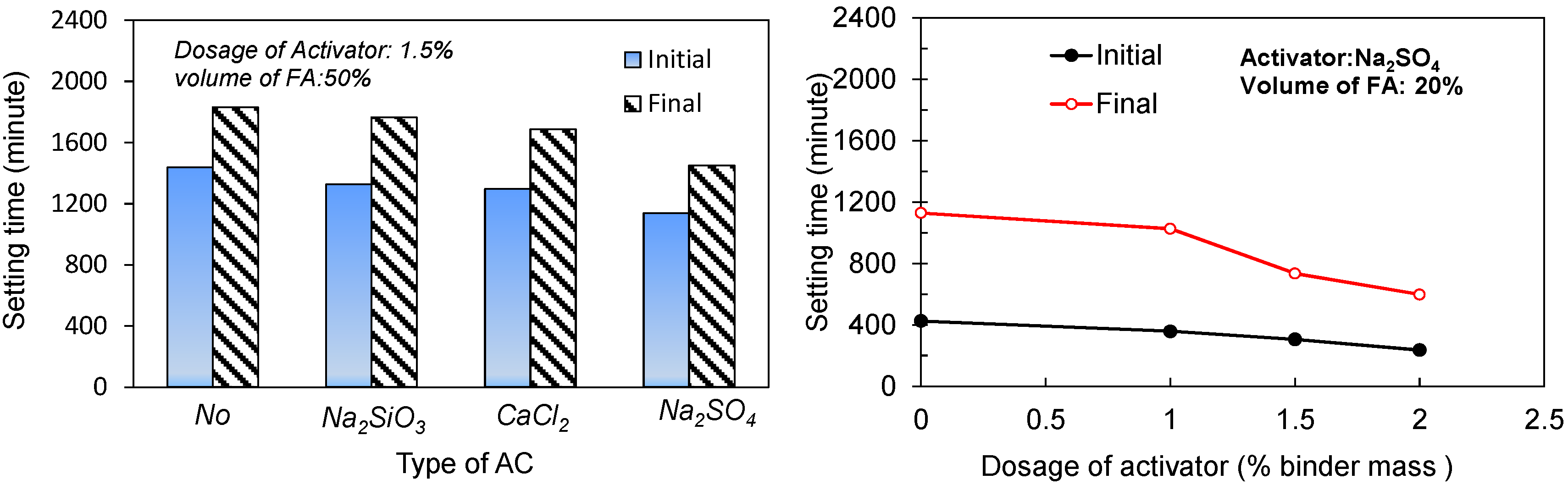
Due to the endeavored studies focusing on the compressive strength of fly ash concrete having been conducted adequately, this paper mainly discusses the effect of ACs on the strength of FACs at different curing times. Experimental results show that the activator type has a significant effect on the compressive strength of FAC, as shown in Figure 4. Regardless of the w/b ratio of concrete (e.g., C40 and C60 in Figure 4), compared to other activators, the activity effectiveness from a compound consisting of Na2SO4 (AC2) is higher than others with a dosage of 1.5%. With increasing curing time, under the promotion of activator Na2SO4 in FA in concrete, the compressive strength of FACs also can attain 92% of one of the conventional concretes at the 90th day. This exhibits the positive effect of activators on the strength development of FAC at the later stage. However, this is different with the curing age of 28 days of conventional concretes, which usually reach a relatively stable compressive strength level. Based on the above, in the following sections, this paper will focus on the investigation and analyses of FACs activated by sodium sulfate (Na2SO4).

3.2. Setting Time

3.2.1. Effect of Fly Ash Dosage

Figure 5 shows the effect of the mass of FA on the initial and final setting time of FAC/HVFAC with or without AC (Na2SO4). When the mass of FA increases, the initial and final setting times of the concretes both increase distinctly, and two kinds of setting times both ascend linearly at an approximate rate with/without AC Na2SO4. For example, when 70% of the cement was replaced by FA and 1.5% of the activator (Na2SO4) was used in concrete, the initial and final setting times of FAC increased to 6.6- and 3.5-times the ones of the conventional concrete, respectively. For the specimens without activator, similarly, when 70% of the cement was replaced by FA, the initial and final setting times of FAC are 7.3- and 1-times the ones of PC concretes, respectively. This can be attributed to the use of FA increasing the effective w/b of concrete, that then decreased the actual used cement amount in concrete. Due to FA having a relatively low activity compared to cement, the hydration speed of all cementitious materials has been reduced overall. In addition, AC effectively promotes the activity of FA in the FAC hydration system, which then results in a lower setting time that can be obtained in the concretes compared to the others.

3.2.2. Effect of the Type and Dosage of Activators
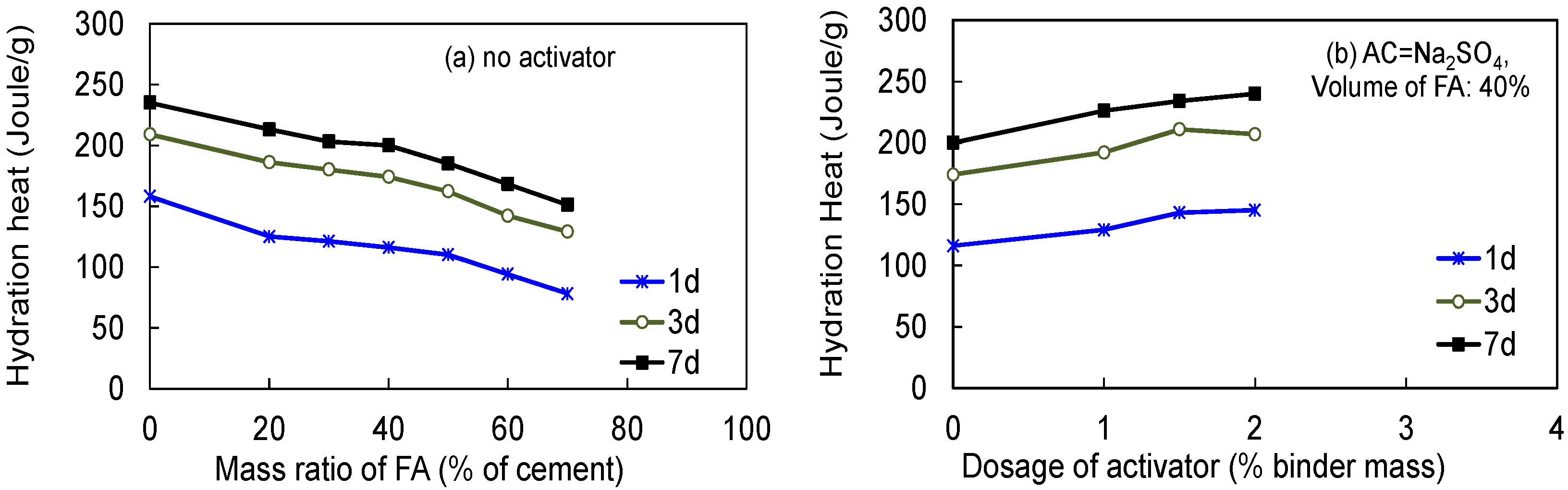
As shown in Figure 6, the type and dosage of AC both have a significant influence on the setting time and other properties of FACs, especially the ones at early stages. Compared to the control concrete, the concretes contain the chemical agents sodium silicate (Na2SiO3), calcium chloride (CaCl2) and sodium sulfate (Na2SO4), all having lower initial setting times, decreasing with degrees of 7.8%, 9.8% and 21.0%, respectively. Similarly, their final setting times decrease by 4%, 7% and 20%, respectively. This can be explained by Na2SO4 being able to promote the hydration reaction with active Al2O3 and SiO2 in fly ash and being able to increase the hydration products of cement and lime to form hydrated calcium aluminate and hydrated calcium silicate, which is helpful to enhance the overall hydration reaction rate of the system and shorten the setting time of concretes. Subsequently, to investigate the more detailed effect of the activator of Na2SO4, using an FAC with 20% of FA and activated by Na2SO4, as shown in Figure 6, the effects of the dosage of Na2SO4 on the initial and final setting times of FACs were provided. The result shows that the initial and final setting times of FACs both decrease with the dosages of AC, especially for the final setting time. When the dosage of AC is 2% of cement, the final setting time of FAC is only 47% of the one of the FAC without AC. Results from the above analyses can illustrate that Na2SO4 can effectively promote the hydration action of HVFAC and reduce the setting time. In other words, the setting time of FAC can be adjusted through controlling the dosage of the activator Na2SO4 in FACs.

3.3. Hydration Heat

3.3.1. Effects of the Dosage of Fly Ash

Figure 7a shows the effect of FA on the hydration heat of the FA-PC system with w/b of 0.41 and without any activator. It can be found that the hydration heat of the FA-PC system decreases with the increasing of the FA content. FA can reduce the hydration heat of FA-PC mixtures significantly, especial at early stages. In this figure, when the mass replacement of FA is 20% of PC, the hydration heats of the mixtures can be reduced by 28%, 16% and 13% of the ones of the control concrete specimens at 1, 3 and 7 days, respectively. Besides, the decrease in the amplitude of the hydration heat of all of the mixtures decreases with curing ages. Additionally, as shown in the figure, when the replacement mass of FA increases, the maximum reduction amplitudes of hydration heat are 51%, 38% and 35% for the mixtures at 1, 3 and 7 days, respectively. This verified that FA can effectively decrease the release of the hydration heat of concrete, especially at the early age, which is very important to mass concretes. On the other hand, the heat difference between one day and three days verifies that the main heating occurs at the early stage.

3.3.2. Effect of Dosage of AC

As some representatives, the effect of dosages of AC (Na2SO4) on the hydration heat of FA-PC systems with a w/b of 0.41 and an FA replacement ratio of 40% is presented in Figure 7b. At the same curing age, an increasing dosage of Na2SO4 can make the hydration heat of FA-PC systems linearly increase with a similar ascending trend, i.e., the ones at 1, 3 and 7 days. Besides, the increase in the magnitudes of hydration heats of concrete are 25%, 19% and 20% at curing ages of 1, 3 and 7 days when the dosages of Na2SO4 ranged from 0–2.0%, respectively. Furthermore, the increase of hydration heats caused by increasing the AC dosage becomes more stable when the curing ages of FA-PC system with Na2SO4 increases. In addition, when the dosage of AC is the same level, the curing age also affects the increase of the hydration heat of the FA-PC system evidently. For example, when the curing age ranged from 1–3 days, the hydration heat FACs without Na2SO4 and using 2.0% of Na2SO4 increased by 50% and 43%, respectively. When the curing age ranged from 3–7 days, however, the hydration heats of FACs with 0% and 2.0% Na2SO4 increased by 15% and 16%, respectively. This indicates that Na2SO4 effectively stimulates the activity of fly ash and promotes hydration reactions in concrete, which then results in an increase of the hydration heat of the FA-PC system at the early age. On the other hand, as shown in Figure 7, as the FAC without activator, the hydration heating of FAC using Na2SO4 occurred mainly within the curing age of 1–3 days, e.g., the heating has increased more from the first to third day with/without activator than the one from 3–7 days.

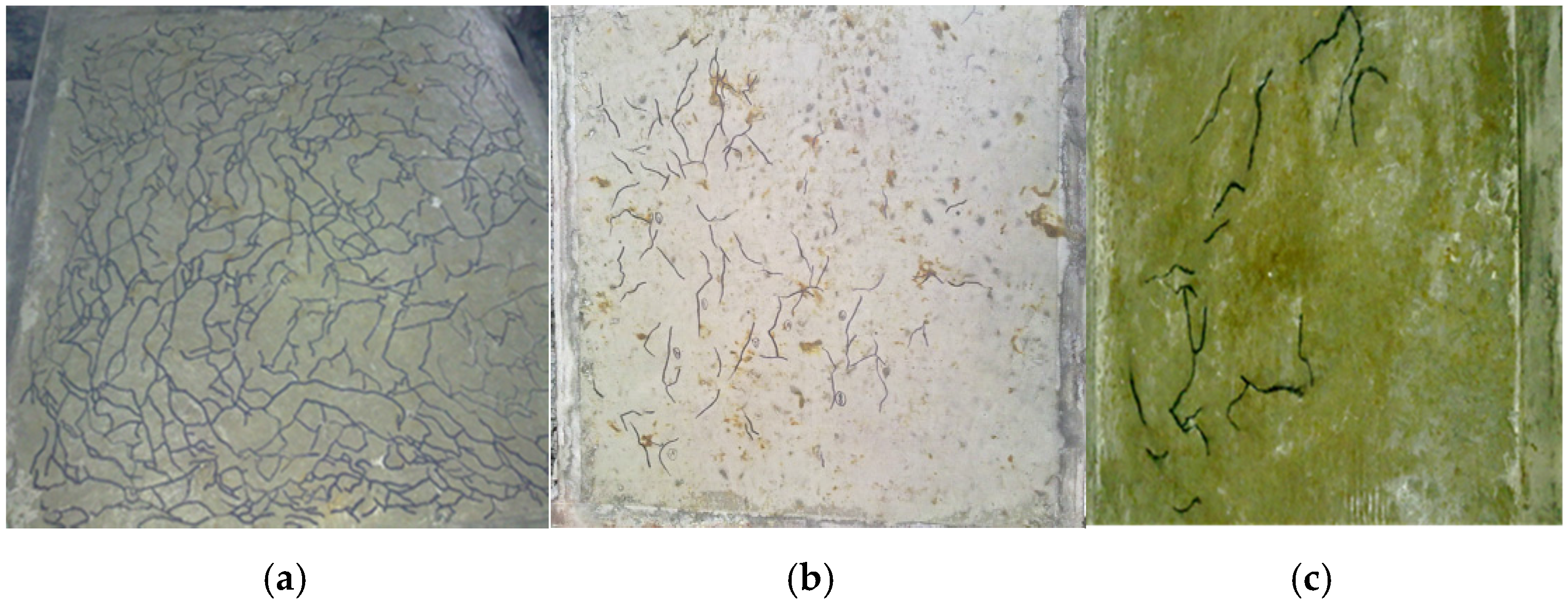
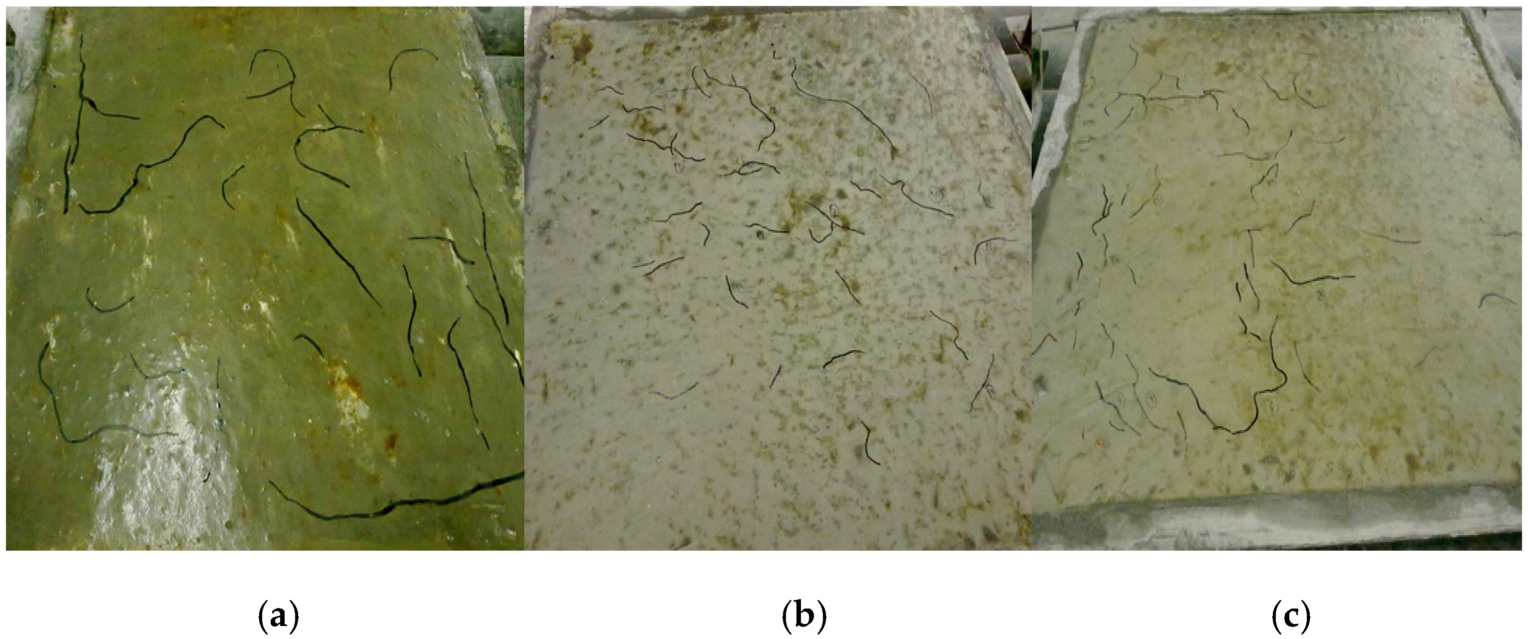
3.4. Initial Crack-Resistance Capacity of FAC/HVFAC

In the study, the initial crack-resistance capacity of FACs/HVFACs is investigated via studying and comparing the time of initial crack, total crack area and the maximum crack width of FAC/HVFAC specimens.

3.4.1. General Pattern

The crack patterns of FAC specimens at 27.5 h after initial crack time (Tcr) are shown in Figure 8 and Figure 9. The results show that the used mass of fly ash and the dosage of AC Na2SO4 both affect significantly the crack pattern and development of FACs. The amount of the cracks decreases with the increasing of the mass of FA or the dosage of AC Na2SO4; crack distributions get more dispersive, as well. On the whole, the crack number of the specimens becomes less, and their distribution areas become smaller when the mass of fly ash or AC Na2SO4 increases.

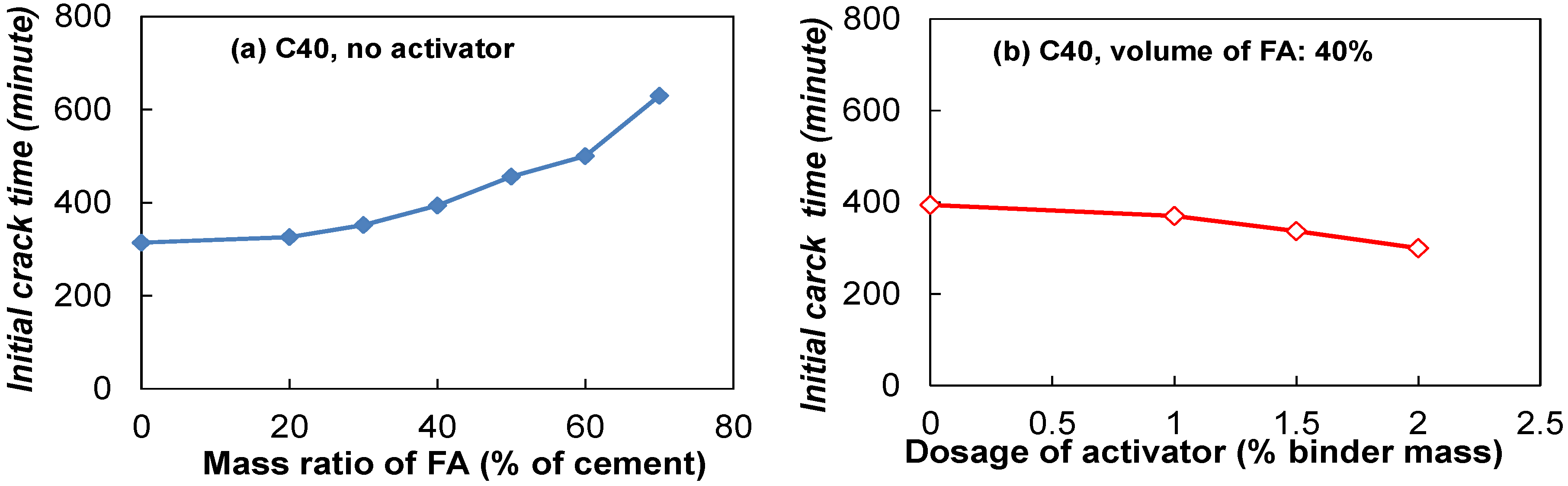
3.4.2. Time of Initial Cracks

The time of the initial crack of concrete is a very important factor that affects significantly the durability life of RC structures, especially external initial cracks, which can sharply increase the corrosion rate of concrete [36]. Figure 9 shows the effects of the mass of FA and AC Na2SO4 on the time of initial cracks in FACs/HVFACs. It is found that increasing FA postpones the occurrence of initial cracks, especially for HVFACs. The use of 70% of FA delays the initial crack time of FAC without activator to 600 min, which is two-times the one obtained in conventional concrete. On the other hand, as shown in Figure 10b, the increase of the dosage of AC Na2SO4 has resulted in the decrease of the initial time of crack, which means more AC Na2SO4 makes FACs easily crack at initial stages, though they improve the early properties of concrete. For instance, when the dosage of Na2SO4 reaches 2% of the cementitious material in concrete, the initial crack time of FAC using 40% FA has been shortened by 70 min compared to the one without activator. This implies that though AC can make FA in PC concrete have higher activity and improve the hydration of the FA-PC system, its dosage should be controlled to avoid the earlier emergence of the initial crack in the concretes.

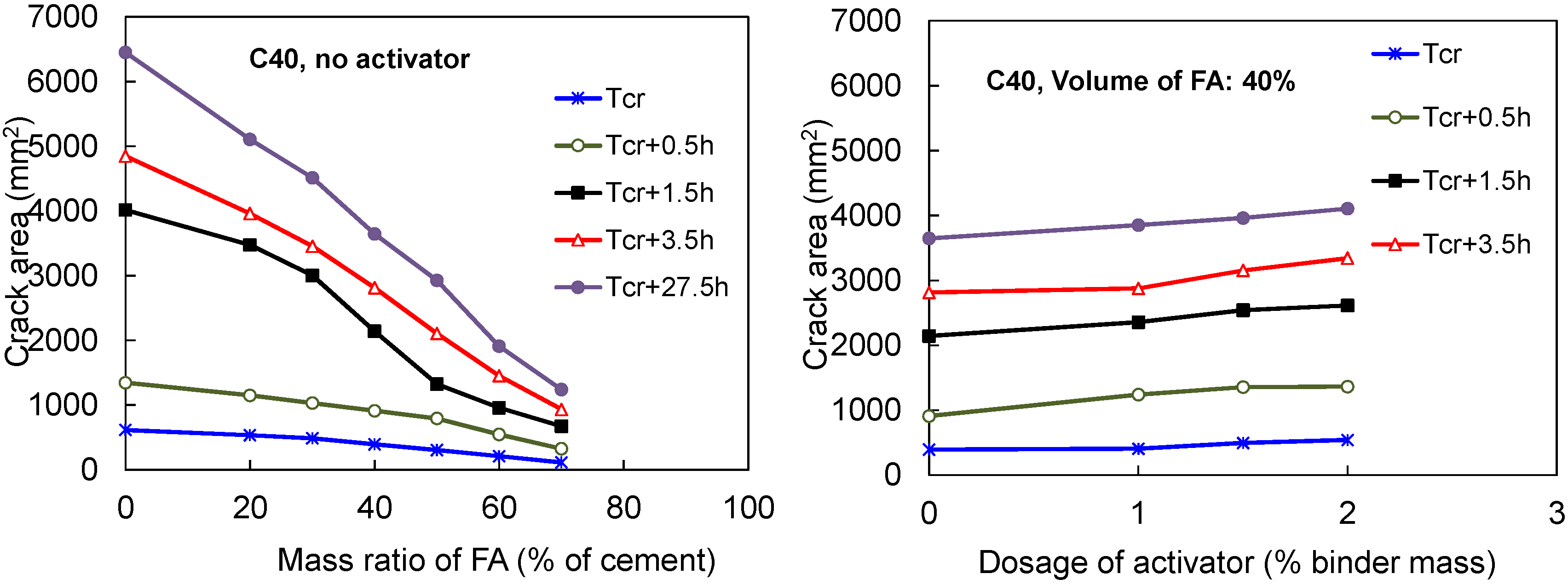
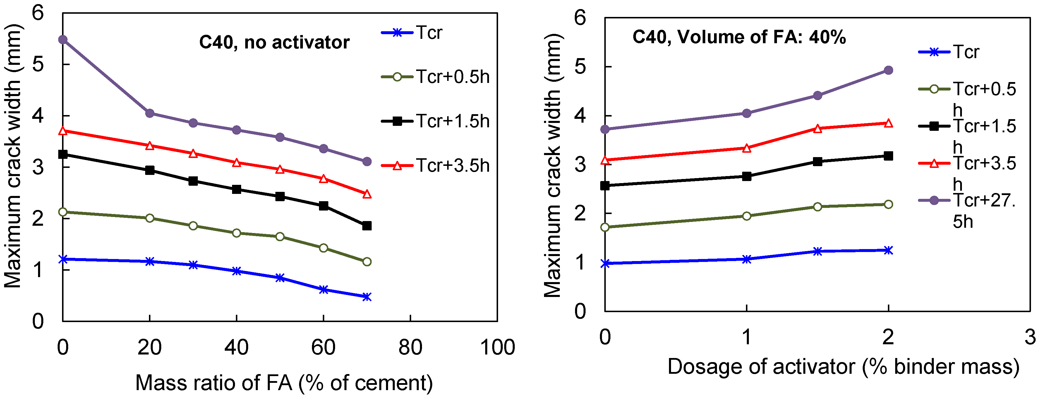
3.4.3. Total Cracked Area and Maximum Width of Cracks in FACs

Figure 11 shows that the total cracked areas of concretes decrease evidently when the mass of FA increase, especially for the specimens with a longer curing time. For control concretes, the total area of cracks at 1.5 h after the occurring of initial cracks (Tcr + 1.5 h) increases remarkably to eight-times the one corresponding to that at the initial crack time (Tcr). When FA is added into PC concrete, the total areas of the cracks start to decrease, and the decreased amplitude becomes more significant after Tcr + 1.5 h, especially in HVFAC specimens. The total cracked area of FAC at Tcr + 27.5 h is only 18% of that of conventional concrete when concrete uses FA to replace 70% of cement. Moreover, with the increase of FA in concrete, the increased rates of total crack areas caused by the increase of curing time decrease obviously. For example, in the control concrete and FAC specimen using 70% FA, the increased levels of their total crack areas are 7.13- and 4.30-times when the curing time ranged from Tcr to Tcr + 27.5 h, respectively.
On the other hand, as plotted in Figure 11, it is found that when the same dosage of AC Na2SO4 is added into FAC, the total cracked areas increase smoothly in FACs with/without AC Na2SO4 as the increase of curing time. However, when the dosage of AC increases, the total areas of cracks increase gradually with the similar increased magnitude for all tested specimens. As described previously, it also indicated that the use of AC (Na2SO4) in FAC should be carefully decided for the cracking.
Even though concrete can work with a suitable amount of cracks, too wide of a crack also can make concrete structures be subjected to serious safety problem. Figure 12 shows the maximum crack widths of FACs. Similar to the effect of FA content on the total cracked area of FAC, FA affects the maximum crack width significantly, and the maximum crack widths decrease when the used mass of FA increases. Under the same curing time, the crack width decrease rates of FAC specimens without AC Na2SO4 caused by the increase of FA content are similar. Additionally, the decrease of the amplitudes also is similar when FACs have the same curing time (after the initial crack) and without AC (Na2SO4). On the contrary, for the effect of AC, when the dosage of AC increased, the maximum crack widths of all specimens increase gradually. At the same curing time, the increase in the amplitudes of the maximum crack width of these FACs is similar. Meanwhile, these increased amplitudes all become stable when the dosage of AC (Na2SO4) exceeds 1.5% of the binder in the concretes.

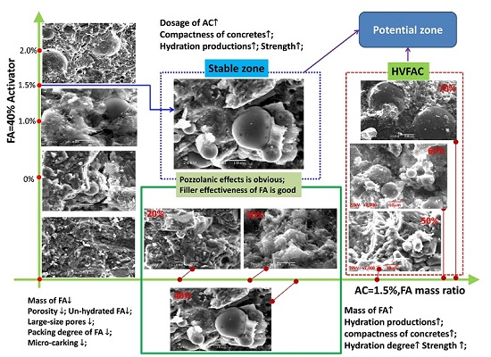
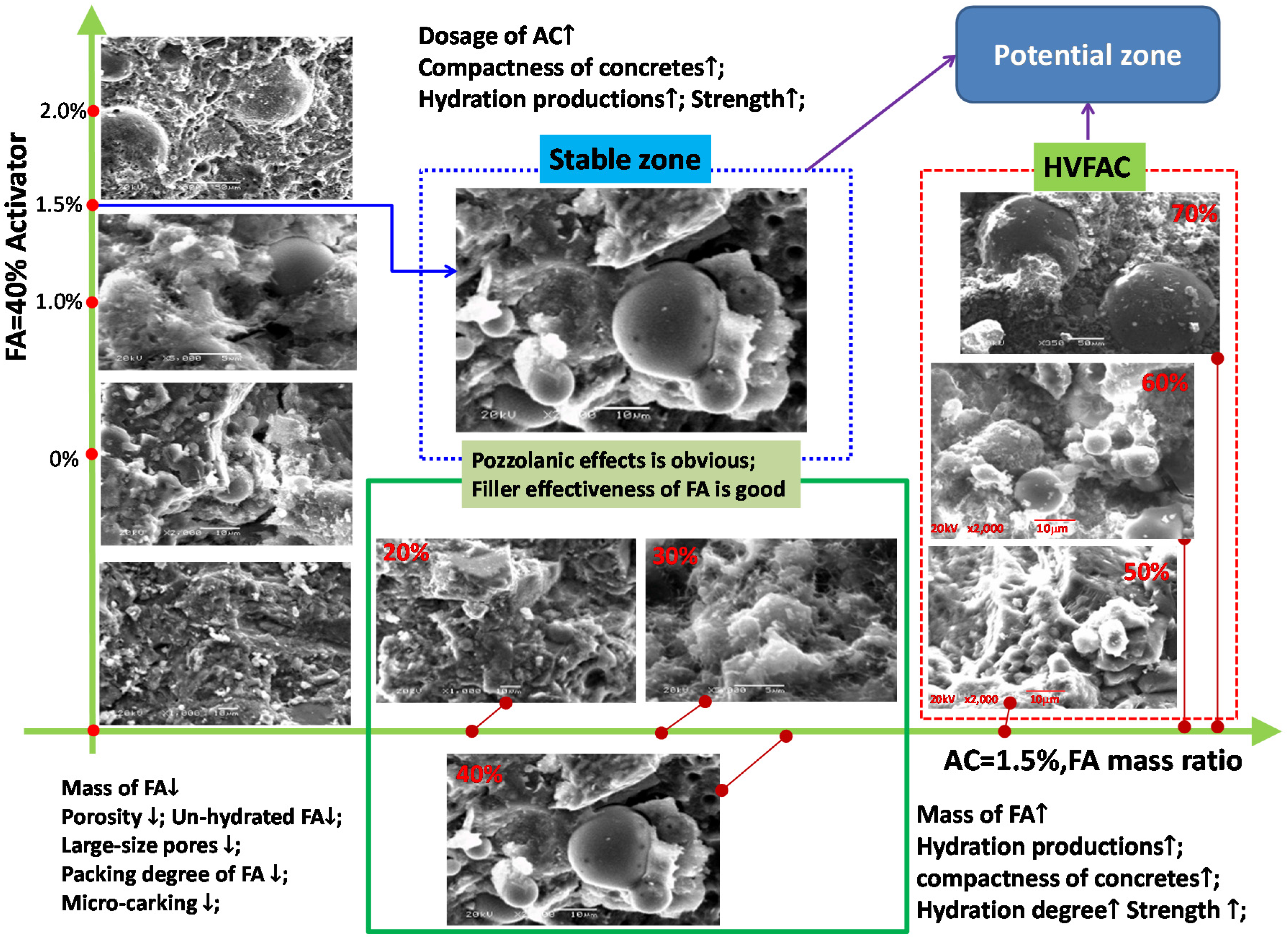
3.5. Microstructure Analyses

The microstructure of concrete is very significant to the strength and durability properties of concrete. Figure 13 shows the SEM pictures of the FACs using different FA contents or AC dosages. The result shows that the control concrete has a compact internal structure because more hydration production can be provided from the PC hydration reaction. This is very helpful for the early strength development of concrete, but the hydration heat should be paid attention to in this concrete, as described previously. When FA replaced 50% of PC or more, many un-hydrated FA particles and less hydration production were observed. At the same time, the concretes using 50% or more FA present low compactness, large porosity and some micro-cracks, which then all affect the strength development of the concrete. In particular, when the FA content was 70% of PC, the hydration degree of the system is significantly lower than the control one, and many raw fly ashes exist as separate particles, so a loose internal structure was provided. On the other hand, when FACs used 20%–40% FA, the Pozzolanic and micro-aggregate effects of FA make FACs obtain a complete hydration reaction and high compactness internal structures when FA increases. On the other hand, from the viewpoint of the packaging of FA particles, when the FA content was controlled to be less than 30% of PC, many hydration productions can wrap the FA particles well, which makes concrete obtain a compact internal structures and good strength development. In addition, when HVFACs (FA = 50% of PC) were activated by AC Na2SO4, with the increase of AC Na2SO4, concrete compactness, hydration production and the wrapping degree of FA particles all have been improved. However, when the dosage of Na2SO4 exceeds 1.5% of PC, the internal porosity of concrete increases strikingly, which affects the development of concrete strength and durability. Based on the above analyses, to obtain a better early strength and properties, the application ratios of FA and AC Na2SO4 should be designed as up to about 40% and 1.5% of PC, respectively. This design method can be called a stable utilization zone of FA in concretes. Comparing to this, when using more FA in concrete, such as 50% of PC, a potential utilization zone of FAC activated by the chemical agent is expected in future research.

4. Models and Discussion

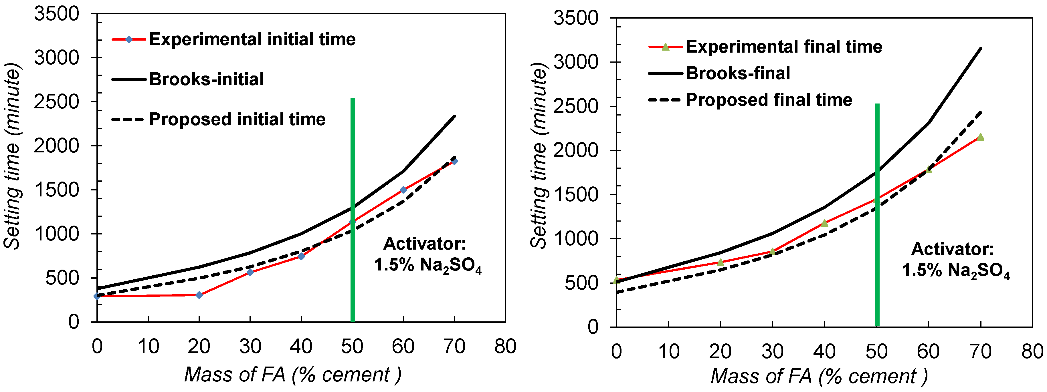
4.1. Existing Method for Predicting the Setting Time of FACs: Brooks Model

Based on a theoretical initial spacing between the particles of un-hydrated cementitious material and the rate of growth of the hydration products, Brooks [37] proposed a model for predicting the initial setting time (TI) of concrete with and without fly ash, as shown in Equation (1). In this model, the following factors have been considered to quantify: the fineness and specific gravity of cementitious material, water/binder ratio, temperature and the chemical composition of the blended cement. Meanwhile, according to this model, the final setting times (TF) of FACs are linearly related to their initial times with a low error coefficient that can be given by Equation (2).
Initial time:
T I = R I S R K T 3 k γ b c S b c [ 1.613 ( 1 + γ b c w c ) 1 3 1.0 ]
where:
  • RIS: relative initial setting time;
  • RKT: relative rate coefficient taking into account the effect of temperature on setting;
  • k: a rate coefficient that represents the rate of growth of the initial hydration;
  • Sbc: the specific surface area of the blended cement;
  • 1/γbc: the volume of blended cementitious materials per g;
  • w/c: water/cement ratio;
Final time:
T F = 1.35   T I
In Equation (1), a combined specific gravity of the FA-PC system should be used as the form of the volume of blended cementitious material per g (1/γbc), which is calculated as Equation (3). It should be noted, according to the selected FA and cement, that the volume ratio of FA in this equation is 0.8-times its mass ratio.
1 γ b c = 1 100 [ 100 R γ c + R γ m a ]
where R is the mass percentage of the mineral admixture replacing cement. γma is the specific gravity of the mineral admixture.
For this model, the specific surface area of blended cement Sbc will be considered as the ratio of FA (R) and the total surface area of cement (Sc) in concrete, as given in Equation (4). In this paper, the specific surface of mineral admixture (FA) Sma can be obtained from previous studies [4,9], which is related to the fineness of the mineral admixture given as the percentage retained on a 45-µm sieve which is given as,
S b c = 1 100 [ S c ( 100 R ) + S m a R ]
S m a = 425 + 9.5 ( 100 P μ 45 )
Besides, Brooks’ model considered that the setting rate coefficient can be presented as a consistent trend when the chemical composition of blended cement was described as a blend oxide ratio, CaO/(SiO2 + Al2O3 + Fe2O3), which is shown as Equation (6). In this study, little lime (CaO) (10% of cement mass) is considered in the calculation of this oxide ratio, as well.
k × 10 4 = 0.192 × ( C a O S i O + A l 2 O 3 + F e 2 O 3 )
At the same time, the effects of temperature (T) and the dosages of a highly-effective water-reducing admixture (D) on the hydration heat of FAC have been considered in the model, via using two factors, RKT and RIS, shown in Equation (1), given in Equations (7) and (8), respectively.
R K T = 0.0333 ( T + 10 )
R I S = 1 + 0.038 D 1.73
In this study, the specific gravity of Portland cement and FA are taken as 3.14 and 2.42, respectively. The fineness of cement and the temperature of concrete construction are taken as 350 m2/kg and 26 °C, respectively. Because the effect of AC on setting had not been taken into account in Brooks’ model, the predicted setting times with the increasing FA will overestimate the corresponding experimental setting times in theory. These actions mainly are expressed as the effect of CaO at the initial stage and the one of AC Na2SO4 at the late stage. For this, the predicted setting times based on the above model and the experimental data of the specimens with ACs CaO (10%) and Na2SO4 (1.5%) were used in this research. Results in Figure 14 verified the over-evaluation, especially in HVFACs, and the predictions are higher with a similar degree based on the experimental results.
Therefore, for FACs with 10% CaO and 1.5% activator Na2SO4, based on the experimental observations in this paper (see Figure 14), the following calculation formulas for predicting the setting times of FAC are proposed based on the above model. For simplicity, the initial setting time of FAC can be considered as 80% of the ones in Brooks’ model, and its finial setting time is taken as 1.3-times the proposed initial setting time , i.e.:
Initial setting time of FAC activated CaO (10%) and Na2SO4 (1.5%)—TI-ac:
T I a c = 0.8 × R I S R K T 3 k γ b c S b c [ 1.613 ( 1 + γ b c w c ) 1 3 1.0 ]
Final setting time of FAC activated CaO (10%) and Na2SO4 (1.5%)—TF-ac:
T F a c = 1.3 T I a c
Using the proposed Formulas 9 and 10, the initial and final setting times of FACs can be calculated, and a good agreement is obtained between the predictions and test data, as shown in Figure 14 Comparing to the original Brooks, this model improves the evaluation of the initial and final setting time of the FACs activated by AC Na2SO4 (1.5%), especially the ones of HVFACs.

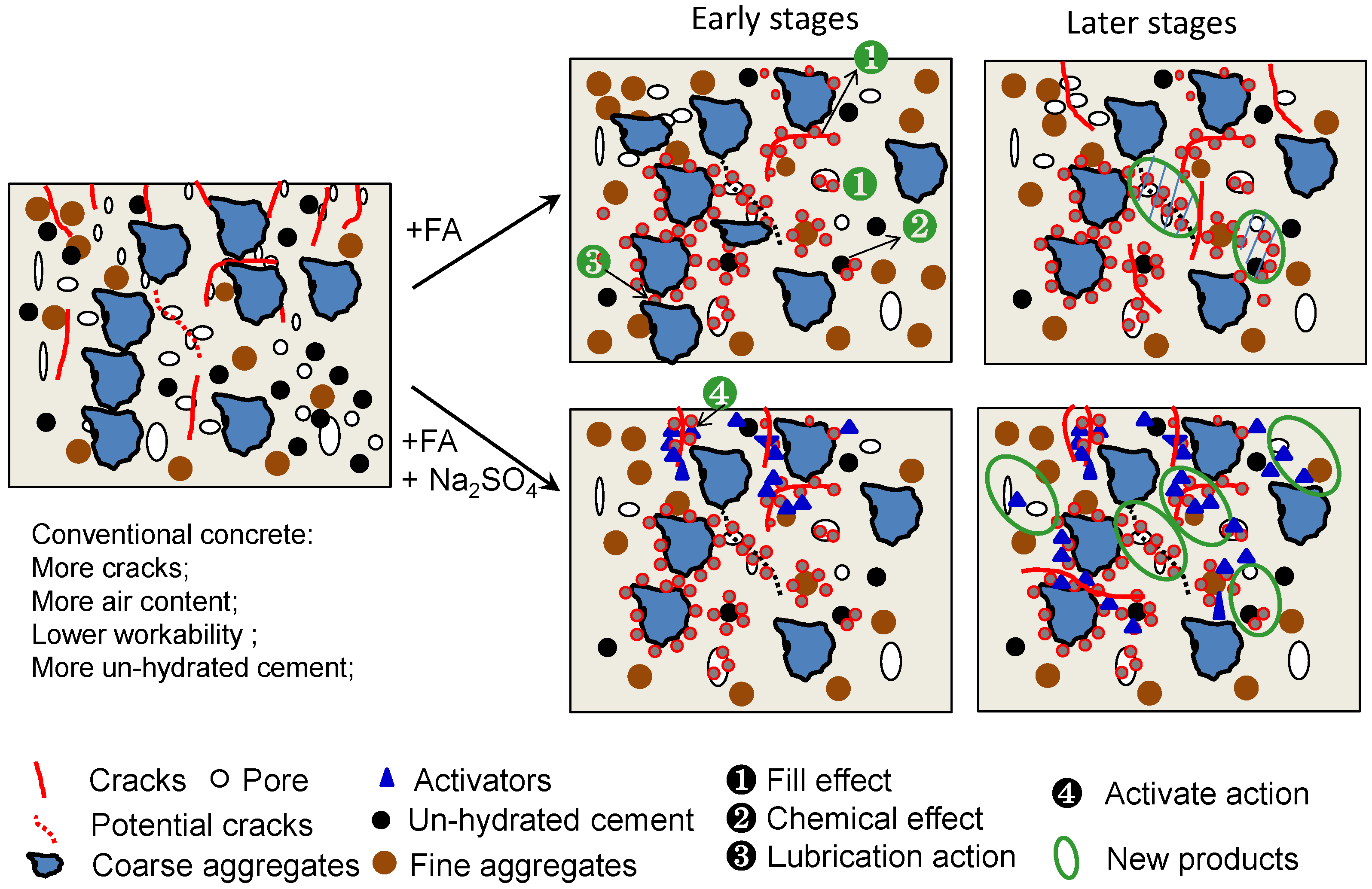
4.2. Mechanism Analysis of Crack-Resistance of FAC Using Na2SO4

As described previously, the use of FA in concrete improves the crack devolvement of the concrete at the early age effectively, such as postponing the time of wider cracks or delaying cracks and reducing the total cracked area. On the other hand, moderate CaO and Na2SO4 promote FA in FACs to obtain better strength development and setting time, but also increase the hydration and cracking of concrete, as well. Therefore, the authors suggest using about up to 50% FA and 10% CaO + 1.5% Na2SO4 can make FACs more acceptable and have better comprehensive properties. In summary, based on this and previous studies, the crack-resistance mechanism of FACs can be explained from the following four aspects, shown in Figure 15.
Filling effect of FA: Comparing to the particles of Portland cement, FA particles with smaller diameters can fill the fissures between aggregates and pores, which then can improve the compactness of concrete and reduce its porosity, and can affect the development of potential crack, shown as ❶ in Figure 15.
Chemical effect of FA: FA can generate more hydrated calcium silicate (C-S-H) and hydrated calcium aluminate in concrete to improve the compactness and hardness of concrete as the increase of curing time. The process reduces the effective water/binder of concrete and improves the compactness of concrete, shown as ❷ in Figure 15.
Lubrication action of FA: As described previously, FA can improve the workability of concrete, which then avoids the excessive concentration of coarse aggregates and un-hydrated cement. This can mitigate the internal deformation of the mixture caused by the internal stress generated from the uneven distribution of coarse aggregates, especially for the mixture around these aggregates, shown as ❸ in Figure 15
Moderate activator CaO and Na2SO4 in FAC: If FA in concrete is activated moderately via adjusting the dosages and type of chemical ACs, the hydration of concrete is accelerated, its hydration heat increased suitably and the setting time of concrete reduced with a low degree, and more C-S-H can be obtained to improve the compactness of concrete at early stages, shown as ❹ in Figure 15. The process is attributed to the combined activator CaO and Na2SO4 increasing the hydration reaction of the active Al2O3 and SiO2 of fly ash and the hydration products of cement. Meanwhile, lime CaO increases the reaction resource of the productions of hydrated calcium aluminate and hydrated calcium silicate.

5. Conclusions

In this study, the influences of several main variables on the hydration heat, setting time, microstructure and crack-resistance properties of FACs/HVFAC are investigated. The main results and proposals can be drawn as follows:
(1) Fly ash can effectively decrease the release of hydration heat, and the hydration heat decreases gradually as the mass of fly ash increases. Meanwhile, the decrease in the magnitude gets smaller when the curing age increases.
(2) The combined activator CaO and Na2SO4 can effectively stimulate the activity of fly ash and decrease the setting time of FACs with the increase of the dosage of the activator. However, if the used dosage of the activator (Na2SO4) is too high, the hydration heat of the FA-PC system and the crack development of FACs both will increase with the activator.
(3) With the addition of fly ash, the initial and final setting times of FACs both increase distinctly. On the other hand, when activator CaO + Na2SO4 is used, the initial and final setting time of FACs both decrease as the dosages of activator increase. Based on this, this study considered that the initial and final setting times of FAC activated by CaO (10%) and Na2SO4 (1.5%) can be 80% of the predictions of Brooks’ model and 1.3-times the proposed initial setting time, respectively.
(4) Fly ash activated by CaO + Na2SO4 can postpone the occurrence of initial crack, decrease the total cracked area of and maximum crack width of FACs/HVFACs. With the increase of curing time, the total cracked areas increase in FAC specimens with and without activator. When the dosage of activator Na2SO4 increases, the total cracked areas of and maximum crack widths of FAC both increase.
(5) Synthetically, comparing to other chemical activators in the paper, 10% of CaO and 1.5% of Na2SO4 can be suggested as the most effective activator for obtaining appropriate hydration heat, setting time and the crack development rate of FACs/HVFACs using low calcium FA at early stages when FA replaces about 50% of PC.

Acknowledgments

The authors are grateful to the fund support from the Natural Nature Science Foundation of China (No. 51202222).

Author Contributions

Jun Zhao conceived of and designed the experiments. Gaochuang Cai analyzed the data, developed the models and wrote this paper. Hervé Degée analyzed the test data and wrote this paper. Bo Huang and Zhongtao Luo performed and completed the experiments.

Conflicts of Interest

The authors declare no conflict of interest.

References

  1. Bilodeau, A.; Malhotra, V.M. High-volume fly ash system: concrete solution for sustainable development. ACI Mater. J. 2000, 97, 41–47. [Google Scholar]
  2. Sivasundaram, V. Thermal Crack Control of Mass Concrete. MSL Division Report MSL 86-93 (IR); Energy, Mines, and Resources Canada: Ottawa, ON, Canada, 1986. [Google Scholar]
  3. Giaccio, G.M.; Malhotra, V.M. Concrete incorporating high volumes of ASTM Class F fly ash. Cement. Concr. Aggregates 1988, 10, 88–95. [Google Scholar]
  4. Langley, W.S.; Carette, G.G.; Malhotra, V.M. Structural concrete incorporating high volumes of ASTM class fly ash. ACI Mater. J. 1989, 86, 507–514. [Google Scholar]
  5. Alasali, M.M.; Malhotra, V.M. Role of concrete incorporating high volumes of fly ash in controlling expansion due to alkali-aggregate reaction. ACI Mater. J. 1991, 88, 159–163. [Google Scholar]
  6. Sivasundaram, V.; Carette, G.G.; Malhotra, V.M. Mechanical properties, creep, and resistance to diffusion of chloride ions of concretes incorporating high volumes of ASTM Class F fly ashes from seven different sources. ACI Mater. J. 1991, 88, 407–416. [Google Scholar]
  7. Bilodeau, A.; Sivasundaram, V.; Painter, K.E.; Malhotra, V.M. Durability of concrete incorporating high volumes of fly ash from sources in the USA. ACI Mater. J. 1994, 91, 3–12. [Google Scholar]
  8. Bilodeau, A.; MalhotraI, V.M. Concretes Incorporating High Volumes of ASTM Class F Fly Ashes: Mechanical Properties and Resistance to De-icing Salt Scaling and to Chloride-Ion Penetration. ACI Spec. Publ. 1992, 132, 319–349. [Google Scholar]
  9. Carette, G.G.; Bilodeau, A.; Chevrier, R.L.; Malhotre, V.M. Mechanical properties of concrete incorporating high volumes of fly ash from sources in the US. ACI Mater. J. 1993, 90, 535–544. [Google Scholar]
  10. Bisaillon, A.; Rivest, M.; Malhotra, V.M. Performance of high-volume fly ash concrete in large experimental monoliths. ACI Mater. J. 1994, 91, 178–187. [Google Scholar]
  11. Bilodeau, A.; MalhotraI, V.M. Properties of high-volume fly ash concrete made with high early-strength ASTM Type III cement. ACI Spec. Publ. 1995, 153, 1–23. [Google Scholar]
  12. Sivasundaram, V.; Bilodeau, A.; Malhotra, V.M. Effect of Curing Conditions on High-Volume Fly Ash Concrete Made with ASTM Type I and III Cements and Silica Fume. ACI Spec. Publ. 1995, 154, 509–530. [Google Scholar]
  13. Li, D.; Chen, Y.; Shen, J.; Su, J.; Wu, X. The influence of alkalinity on activation and microstructure of fly ash. Cem. Concr. Res. 2000, 30, 881–886. [Google Scholar] [CrossRef]
  14. ACI Committee 232. Use of Fly Ash in Concrete; American Concrete Institute: Farmington Hills MI, USA, 2003. [Google Scholar]
  15. Malhotra, V.M. Super plasticized Fly Ash Concrete for Structural Applications. Concr. Int. 1986, 8, 28–31. [Google Scholar]
  16. Naik, T.R.; Ramme, B.W.; Tews, J.H. Pavement Construction with High-Volume Class C and Class F Fly Ash Concrete. ACI Mater. J. 1995, 92, 200–210. [Google Scholar]
  17. Poon, C.S.; Lam, L.; Wong, Y.L. A study on high strength concrete prepared with large volumes of low calcium fly ash. Cem. Concr. Res. 2000, 30, 447–455. [Google Scholar] [CrossRef]
  18. Atis, C.D. Heat evolution of high-volume fly ash concrete. Cem. Concr. Res. 2002, 32, 751–756. [Google Scholar] [CrossRef]
  19. Schwarz, N.; Neithalath, N. Influence of a fine glass powder on cement hydration: Comparison to fly ash and modeling the degree of hydration. Cem. Concr. Res. 2008, 38, 429–436. [Google Scholar] [CrossRef]
  20. Balakrishnan, B.; Awal, A.A.; Shehu, I.A. Influence of high volume fly ash in controlling Heat of Hydration of Concrete. Int. J. Eng. Res. Appl. 2013, 3, 932–936. [Google Scholar]
  21. Sakai, E.; Miyahara, S.; Ohsawa, S.; Lee, S.H.; Daimon, M. Hydration of fly ash cement. Cem. Concr. Res. 2005, 35, 1135–1140. [Google Scholar] [CrossRef]
  22. Durán-Herrera, A.; Juarez, C.A.; Valdez, P.; Bentz, D.P. Evaluation of sustainable high-volume fly ash concretes. Cem. Concr. Compos. 2011, 33, 39–45. [Google Scholar] [CrossRef]
  23. Hardjito, D.; Wallah, S.E.; Sumajouw, D.J.; Rangan, B.V. On the development of fly ash-based geopolymer concrete. ACI Mater. J. 2004, 101, 467–472. [Google Scholar]
  24. Rangan, B.V. Mix design and production of fly ash based geopolymer concrete. Indian Concr. J. 2008, 82, 7–15. [Google Scholar]
  25. Barnes, P.; Bensted, J. Structure and Performance of Cements, 2nd ed.; CRC Press: Boca Raton, FL, USA, 2000. [Google Scholar]
  26. Shi, C.; Day, R.L. Acceleration of the reactivity of fly ash by chemical activation. Cem. Concr. Res. 1995, 25, 15–21. [Google Scholar] [CrossRef]
  27. Lee, C.Y.; Lee, H.K.; Lee, K.M. Strength and microstructural characteristics of chemically activated fly ash–cement systems. Cem. Concr. Res. 2003, 33, 425–431. [Google Scholar] [CrossRef]
  28. Zhang, Y.M.; Sun, W.; Yan, H.D. Hydration of high-volume fly ash cement pastes. Cem. Concr. Compos. 2000, 22, 445–452. [Google Scholar] [CrossRef]
  29. Qian, J.; Shi, C.; Wang, Z. Activation of blended cements containing fly ash. Cem. Concr. Res. 2001, 31, 1121–1127. [Google Scholar] [CrossRef]
  30. Chinese Ministry of Construction. GB/T12959–2008 Test Methods for Heat of Hydration of Cement, China National Standard; China Standards Press: Beijing, China, 2008. (In Chinese)
  31. ASTM C186-15A. Standard Test Method for Heat of Hydration of Hydraulic Cement; ASTM International: West Conshohocken, PA, USA, 2015. [Google Scholar]
  32. Chinese Ministry of Construction. GB/T50080–2002, Standard for Test Method of Performance on Ordinary Fresh Concrete; China Standards Press: Beijing, China, 2003. (In Chinese)
  33. Chinese Ministry of Construction. CECS 13–2009, Standard Test Method for Fiber Reinforced Concrete; China Standards Press: Beijing, China, 2009. (In Chinese)
  34. ASTM C1581/C1581M-09a. Standard Test Method for Determining Age at Cracking and Induced Tensile Stress Characteristics of Mortar and Concrete under Restrained Shrinkage; ASTM International: West Conshohocken, PA, USA, 2009. [Google Scholar]
  35. ASTM C1579–13. Standard Test Method for Evaluating Plastic Shrinkage Cracking of Restrained Fiber Reinforced Concrete (Using a Steel Form Insert); ASTM International: West Conshohocken PA, USA, 2013. [Google Scholar]
  36. Yang, Z.; Weiss, W.J.; Olek, J. Interaction between Micro-Cracking, Cracking, and Reduced Durability of Concrete: Developing Methods for Considering Cumulative Damage in Life-Cycle Modeling; JTRP Technical Reports: West Lafayette, IN, USA, 2004. [Google Scholar]
  37. Brooks, J.J. Prediction of Setting Time of Fly Ash Concrete. ACI Mater. J. 2002, 99, 591–597. [Google Scholar]
Figure 1. Setup for the hydration heat test. H1, un-hydrate cement. H2, hydrated cement.
Applsci 06 00224 g001
Figure 2. Instrument and method for the test of setting time. HVFAC, high volume fly ash concrete. FAC, fly ash concrete.
Applsci 06 00224 g002
Figure 3. Crack test in the standard test method of fiber concrete in China [33].
Applsci 06 00224 g003
Figure 4. Effect of activator type (the dosage is 1.50% of the binder) on the compressive strength of FAC.
Applsci 06 00224 g004
Figure 5. Effect of the mass of FA on setting time.
Applsci 06 00224 g005
Figure 6. Effect of the type and dosage of AC on the setting time of FACs. FACs, fly ash concretes.
Applsci 06 00224 g006
Figure 7. Effects of the content of FA and AC on the hydration heat of the FA-PC system. PC, Portland cement.
Applsci 06 00224 g007
Figure 8. Crack morphology of some specimens after (Tcr + 27.5) hours (normal FACs + 10% CaO). (a) FA-0%, AC-0%; (b) FA-40%, AC-0%; (c) FA-70%, AC-0%. Tcr, The time of initial crack.
Applsci 06 00224 g008
Figure 9. Crack morphology of some specimens after (Tcr + 27.5) hours (activated FACs). (a) FA-40%, AC-1.0%; (b) FA-40%, AC-1.5%; (c) FA-40%, AC-2.0%.
Applsci 06 00224 g009
Figure 10. Effects of FA contents and the dosage of AC on the initial crack time of FAC.
Applsci 06 00224 g010
Figure 11. Effects of the mass of FA and the dosage of AC on the cracked area of FACs.
Applsci 06 00224 g011
Figure 12. Effect of the mass of FA and dosage of AC (Na2SO4) on crack width.
Applsci 06 00224 g012
Figure 13. Microstructures vs. properties of FACs.
Applsci 06 00224 g013
Figure 14. Predictions of Brooks and proposed models for FACs with 1.5% of Na2SO4.
Applsci 06 00224 g014
Figure 15. Mechanism of the crack-resistance of FAC activated by Na2SO4.
Applsci 06 00224 g015
Table 1. Physical properties and chemical compositions of cement and Fly Ash II.
Physical Property (%)Type(+) 325 Mesh (+ 44 mm)Water DemandWater ContentIgnition LossSpecific GravityFineness m2/kg
Fly ash II18310.897.12.42-
PC9.526.2-1.93.14350
Chemical compositions (%)TypeSiO2Al2O3Fe2O3CaOMgOSO3Others
Fly ash II57.522.68.54.942.570.53.4
PC22.89.473.455.22.992.151.9
Table 2. Mix proportions of concrete.
GroupsSeries of Test No. 1w/b RatioReplacement Ratio of FAFly ash kg/m3Cement kg/m3Aggregates kg/m3Admixtures kg/m3Lime kg/m3Activator kg/m3
CoarseFine
Compressive + Setting timeC40-FAY-ACZ0.41Y = 0, 0.2, 0.3, 0.4, 0.5, 0.6, 0.7385Y385 (1-Y)10947053.0838.5385Y
C60-FAY-ACZ0.30530Y530 (1-Y)11135627.9538.5386Y
Early crackC40-FAY-ACZ0.41385Y385 (1-Y)10947053.0838.5385Y
1 the specimen CX-FAY-ACZ means a FAC specimen uses CX concrete, FA of Y times the used cement (mass) and Z-type AC
Table 3. Mixture proportion details in the hydration heat group. FA, fly ash. AC, activator.
GroupsTest No. 1Cement (g)Fly ash (g)Water (ml)Na2SO4 (g)Curing Age (Days)
Hydration heatFA00-AC0040010001/3/7
FA20-AC00328
FA30-AC002812
FA40-AC002416
FA50-AC002020
FA60-AC001624-
FA70-AC001228-
FA40-AC1024161000.41/3/7
FA40-AC150.6
FA40-AC200.8
1 where, specimen FAx-ACy means a FAC mortar was made with x% FA (mass of cement) and is activated by y% AC (by mass of binder).

