1. Introduction
The compressed air foam system (CAFS) is a type of fire-extinguishing equipment which generates foam in the form of uniformly sized bubbles of a relatively small size which are injected forcibly with compressed air as an aqueous foam solution. The fixed fire-extinguishing system was initially developed by the National Research Center of Canada (NRCC) in the late 1990s. Currently, this system forms the basis of all foam fire-extinguishing systems. The main action of the foam fire-extinguishing agent is to choke the flame by covering the surface of the combustion product. Foam is created from a mix of an aqueous solution and air. A cooling effect due to the moisture included in the aqueous foam solution is an additional effect. This agent has been used for nearly one hundred years [
1]; however, given the disadvantage of secondary damage caused by water, systems which minimize this problem by reducing the use of fire water and through long-distance discharges at high speeds have been developed and commercialized in Canada and the United States. In addition, Korea recently developed such a system, which has reached the stage of commercialization. The Korea Fire Institute (KFI) has developed an approval program to certify the fire-extinguishing performance of the CAFS [
2].
Various experimental and analytical studies of CAFSs have been conducted. Magrabi et al. [
3] proposed an experimental method to measure the drainage rate of liquid from fire-extinguishing foam for an aqueous film forming foam (AFFF) product and a film-forming fluoroprotein foam product. Lee et al. [
4] studied the fire-extinguishing performance for the oil fire between the general air mixture system (GAMS) and the CAFS in accordance with the discharge flow rate. Feng [
5] analyzed the contributions of various gas-liquid mixing chambers and gas-liquid mixing procedures with regard to the performance levels of CAFSs. Kim et al. [
6] compared the fire-extinguishing performance using the nozzle only for the compressed air foam and the fixed nozzle, respectively. Cheng and Xu [
7] carried out experimental research on the extinguishing effects of the nozzle shape, air pressure and mixing ratio as foam-performance parameters for non-aqueous liquid fuel fires.
In this paper, in order to comprehend the relationship between the mixing ratio of the air-to-aqueous foam solution, which is an important performance factor of the CAFS, and the fire-extinguishing performance of the class B type for oil fires in the CAFS, the fire-extinguishing performance with the air-to-aqueous foam solution is evaluated through a fire-extinguishing experiment.
2. Operation Principle of the Compressed Air Foam System
The CAFS is a fire-extinguishing facility which releases foam which is transferred from a mixing chamber into air through a discharge nozzle or through a nozzle of a discharging device which is connected to a pipe network. The role of the mixing chamber is to blend the air and the aqueous foam solution by compulsion. The compressed air foam created from the combination of water and an undiluted solution of foam is itself combined with pressurized air or nitrogen to become stable and homogeneous. The operating principle of the existing foam fire-extinguishing facility (for example, GAMS) is to provide bubbles which are produced by the aqueous foam solution in the foam mixer and then released through the nozzle and sucked into the external air simultaneously. The operating principle of the CAFS is as follows (see
Figure 1): First, the system forms bubbles which are sent by pressured air to a mixing chamber. These are then discharged through a nozzle and transferred by a network of pipes. In other words, the compressed air is an important factor to produce stable and homogeneous bubbles [
8].
The CAFS works through a choking effect by expanding the volume of the compressed air-foam mixture and increasing the fire-extinguishing effectiveness by increasing the surface area of the compressed air-foam mixture, as the volume and the surface area of the compressed air-foam mixture can be significantly expanded and broadened according to a discharge of the foam with the forcing of air into the aqueous foam solution. Therefore, when the CAFS is applied to the fire-extinguishing facility, it can utilize the relationship of the aqueous foam solution and the foam to control the amount of air which is included in the compressed air foam. If foam with accumulated intake air is generated, it can considerably reduce the degree of damage by water and lead to a substantial time of more than 10 minutes during which the flow is poor when adhering to the surface of the target object, as the reduction time as well as the viscosity of the foam is increased. Because the aqueous foam solution which is consumed is less than the typical great quantity of water used, as illustrated above, the CAFS is also economically beneficial.
3. Experimental Program
3.1. Experimental Parameters and the Physical and Chemical Performance of the AFFF of 3%
Table 1 summarizes the experimental parameters of the specimens. The commercialized mixing ratio of the air-to-aqueous foam solution in several countries ranges from 1:10 to 1:4. The Korean approved standard for the compressed air foam system [
9] also recommends that the mixing ratio of the air-to-aqueous foam solution should range from 1:15 to 1:7. The compressed air foam is divided into wet foam, for which the mixing ratio of the air-to-aqueous foam solution ranges from 1:10 to 1:4, and dry foam, for which it ranges from 1:15 to 1:10. The fire suppression time due to the dry foam increases because dry foam manufactured at less than 1:10 is very light such that the flame stirs up the compressed air foam. For this reason, in this study, the experimental fire-extinguishing performance evaluation of the CAFS was conducted with only wet foam. Three values of the mixing ratio of the air-to-aqueous foam solution (1:10, 1:7, and 1:4) were considered. The foam fire-extinguishing agents were utilized an AFFF of 3% of the type widely used in the Korean fire industry. The generated fuel for the flame used to evaluate the class B fire suppression performance was gasoline of the type used for vehicles to maintain a consistent calorific value.
Table 2 summarizes the physical and chemical material properties for the AFFF of 3% in accordance with the results of the aging test as an important index to determine the performance of the fire-extinguishing agent. In the Korean specification [
10], the fire-extinguishing foam agent after the aging test is defined as the fire-extinguishing agent that is able to conduct two drainage tests: first, to convert to room temperature after maintaining a temperature of 65 ± 2 °C during 216 h, second, to convert to room temperature after maintaining a temperature of −18 ± 2 °C during 24 h again. As shown in
Table 2, the material properties were all satisfied regarding the performance requirements for the AFFF of 3% (the gravity, the kinematic viscosity, the freezing point, the hydrogen ion concentration, and the surface tension) as per the Korean specification. Also, the discharging performance of the AFFF of 3% by the GAMS appears to be enough. However, it has not been regulated yet by the CAFS, even though it may accepted.
For the expansion ratio of the aqueous solution and air, the CAFS shows a better performance than the general foam by the GAMS. The general foam appeared 8.4 to 8.8 times and the CAFS presented 8.9 to 11.4 times. For the 25% drainage time to convert to the water from 25% of the weight of the discharging foam, the general foam took 2 min 42 s to 2 min 48 s; however, the CAFS took 1 min 59 s to 3 min 52 s. For the CAMS, the 25% drainage time after the aging test was short in comparison with that before the aging test. For the CAFS, that tendency is opposite. The 25% drainage time of the GAFS according to the rate of increase of the compressed air is apt to increase. It had the ratio of 1:4, which is similar to that of the general foam.
3.2. Test Set-Up and Measurement Plan
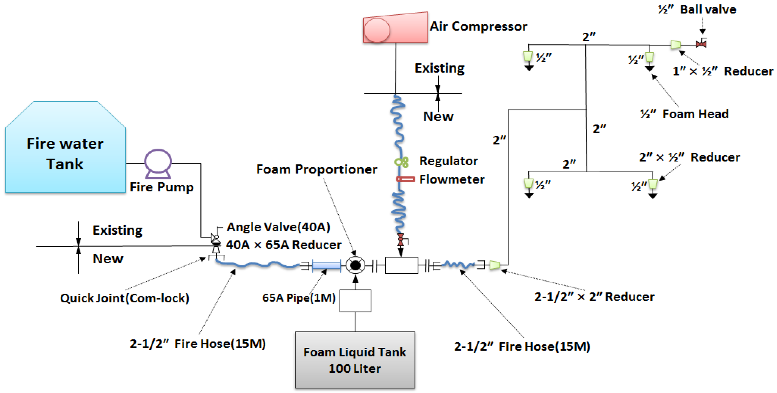
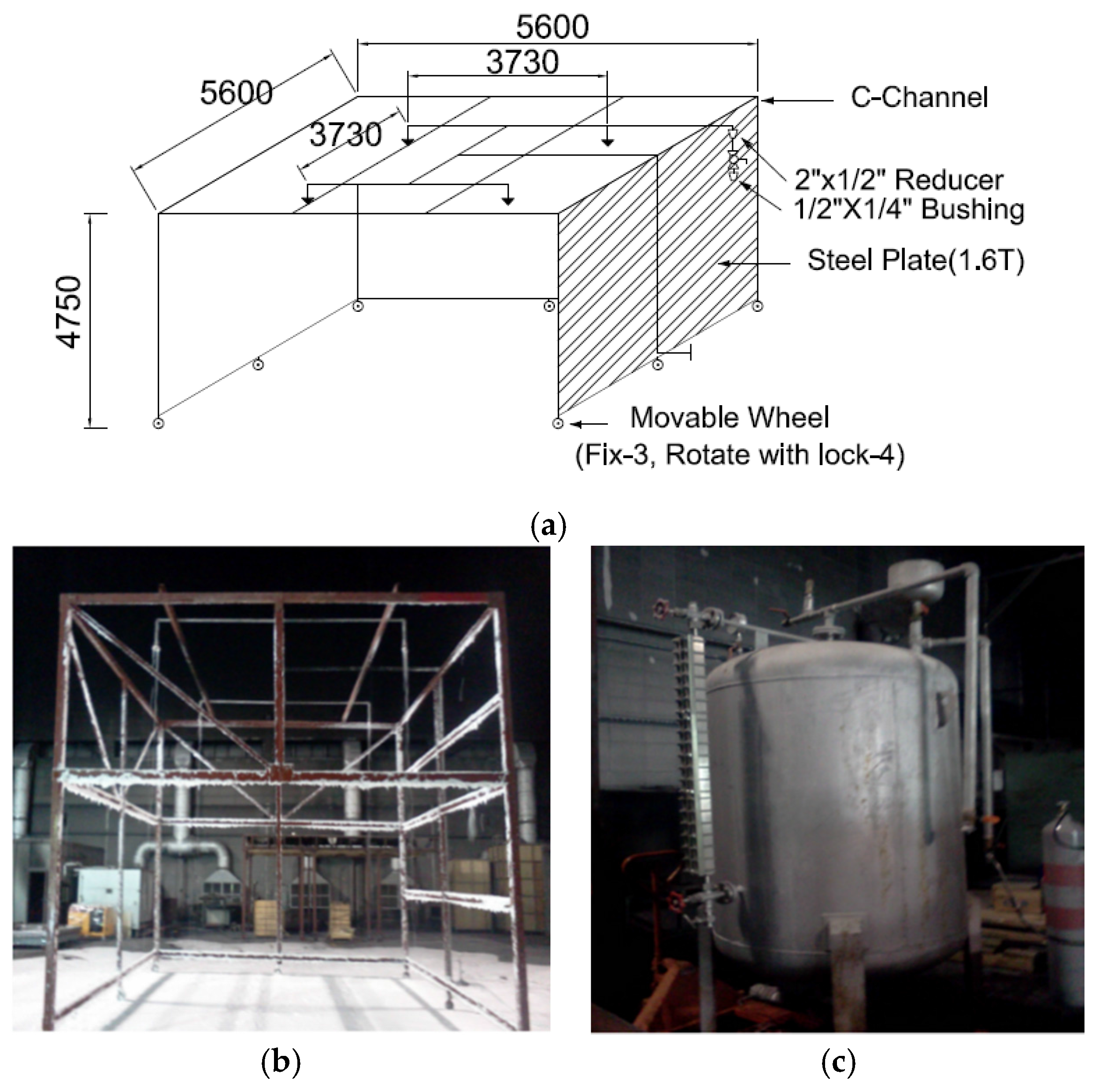
Figure 2a shows an experimental device used to evaluate the fire-extinguishing performance of the CAFS in this study. The experimental device was manufactured as per UL 162 [
11] which is the United States standard, and as per NFPA Code 11 [
12]. Four foam heads were installed in a grid pattern of 3730 mm × 3730 mm. The piping network was established as the tournament type, with a height of 4750 mm. For an explicit determination of the fire-extinguishing performance through an experiment with the CAFS, video cameras which could observe the changes in the flame on both sides were installed. Thermocouple thermometers were set up at 0.5 m, 0.8 m, and 1.2 m for the vertical direction in the middle of the combustion plate to collect data for the temperature change of the flame. Devices to measure the heat flux to confirm the short fire suppression time were also placed at 5 m, 6 m, and 7 m in the horizontal direction in the middle of the combustion plate. The thermocouple thermometers measure the erased temperature of the flame such that they investigate the remaining time of the flame. The measured value of the radiation intensity was determined as a reference point in accordance with the experimental error, identifying that the average intensity of the heat flux of the fire-extinguishing model of 20 units is 5.4 kW, 7 m away from the combustion plate. Furthermore, in accordance with the experimental conditions and analysis of fire suppression effectiveness in the fire-fighting field, a difference in the remaining flame time arises. Therefore, the behavior of the flame was analyzed to measure the thermocouple and intensity of the heat flux together.
Figure 2b,c respectively displays the experimental frame of the CAFS and the storage tank of the aqueous foam solution to manufacture the compressed air for the test. The storage tank of the aqueous foam solution adopted here could convey the aqueous foam solution using the pressure of the high-pressure gas of an appropriate type to inject a certain amount of fluid at a constant flow rate.
3.3. Experimental Method and Performance Evaluation Criteria
Flammable liquid petroleum was adopted as the target pyrogen for the class B fire-extinguishing performance evaluation. The experimental method per Code 2015-68 [
10] and Code 2012-81 [
13] is as follows: (i) Water of 200 L and gasoline for vehicles of 200 L are put into a regular steel pan of 2,000 mm × 2,000 mm × 300 mm (longitudinal length * ordinate length * height) (fire-extinguishing model of 20 units); (ii) Next, this is ignited; (iii) Finally, it is determined whether the flame is extinguished or not to release the foam after 60 s. The discharging pressure of the aqueous foam solution for the experiment, which was utilized to prepare in the storage tank to hole the agent, was 0.7 MPa. In order to mix the compressed air, an air mixer was initially installed in the middle of the pipeline to release the pre-manufactured aqueous foam solution. Subsequently, the high-pressure air was produced by a compressor. The high-pressure air was transferred by a control valve. In the final step, the compressed air was injected into the air mixer through the control valve. For a reference, the guideline for class B fire-extinguishing performance [
10] stipulates that the fire should be suppressed within five minutes after the discharging of the foam.
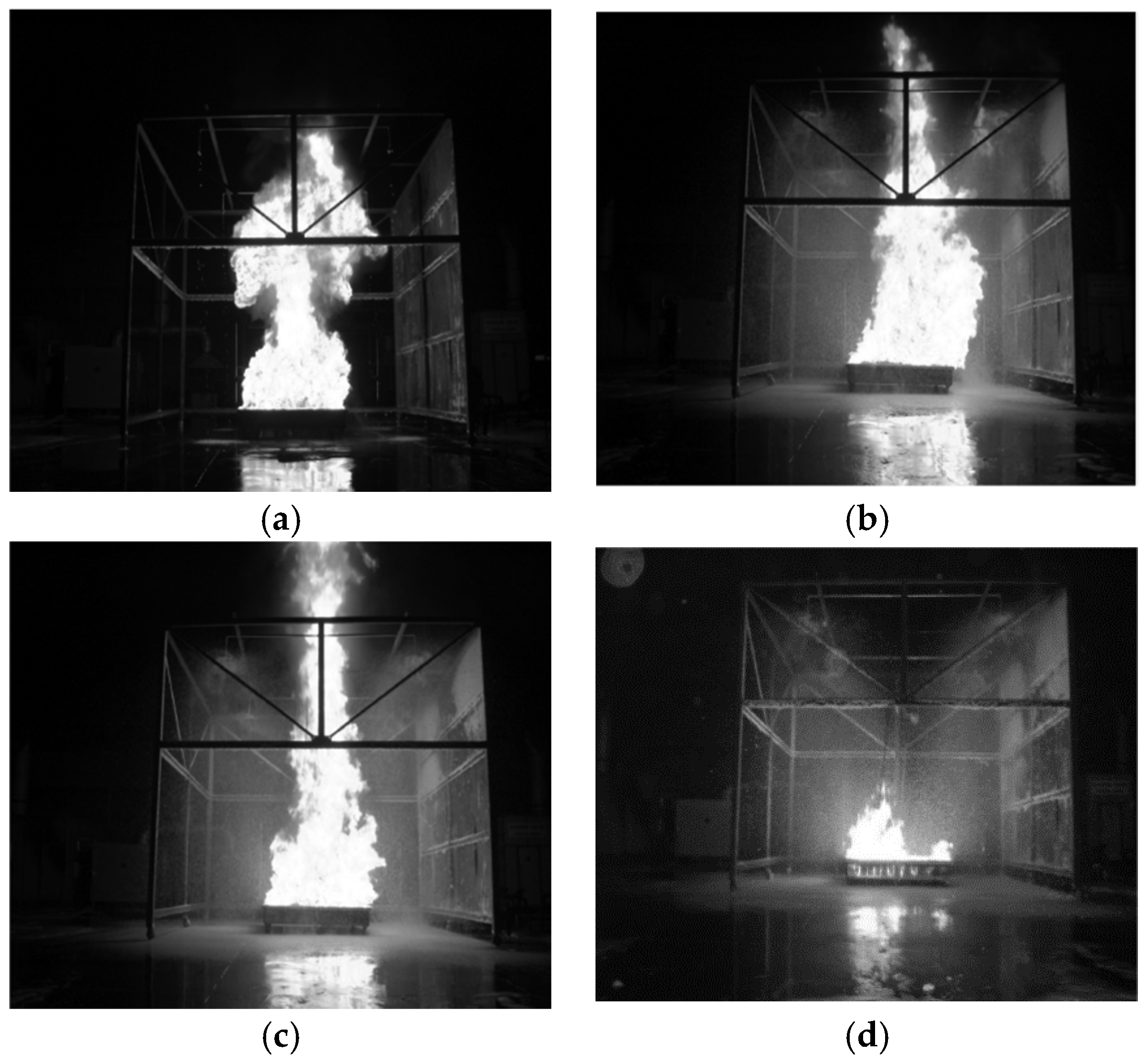
Figure 3a–d depicts scenes throughout the experimental process to assess the fire-extinguishing performance of the compressed air foam system from the ignition time of the gasoline until close to the fire-extinguishing time. The pyrogen of the petroleum generated a mushroom flame during the initial ignition stage (see
Figure 3a). The flame before the discharging foam, for which outside artificial air is not provided, appeared as typical egg-shaped candlelight. After the compressed air foam spouted and while the width of the flame was reduced by the foam, the flame rose up vertically because the air included in the compressed air foam was supplied from the top of the experimental frame (see
Figure 2a and
Figure 3c). However, the flame was diminished gradually due to the continuously discharging compressed air foam (see
Figure 3d).
4. Experimental Fire-Extinguishing Performance Evaluation
4.1. Specimen I
Figure 4 and
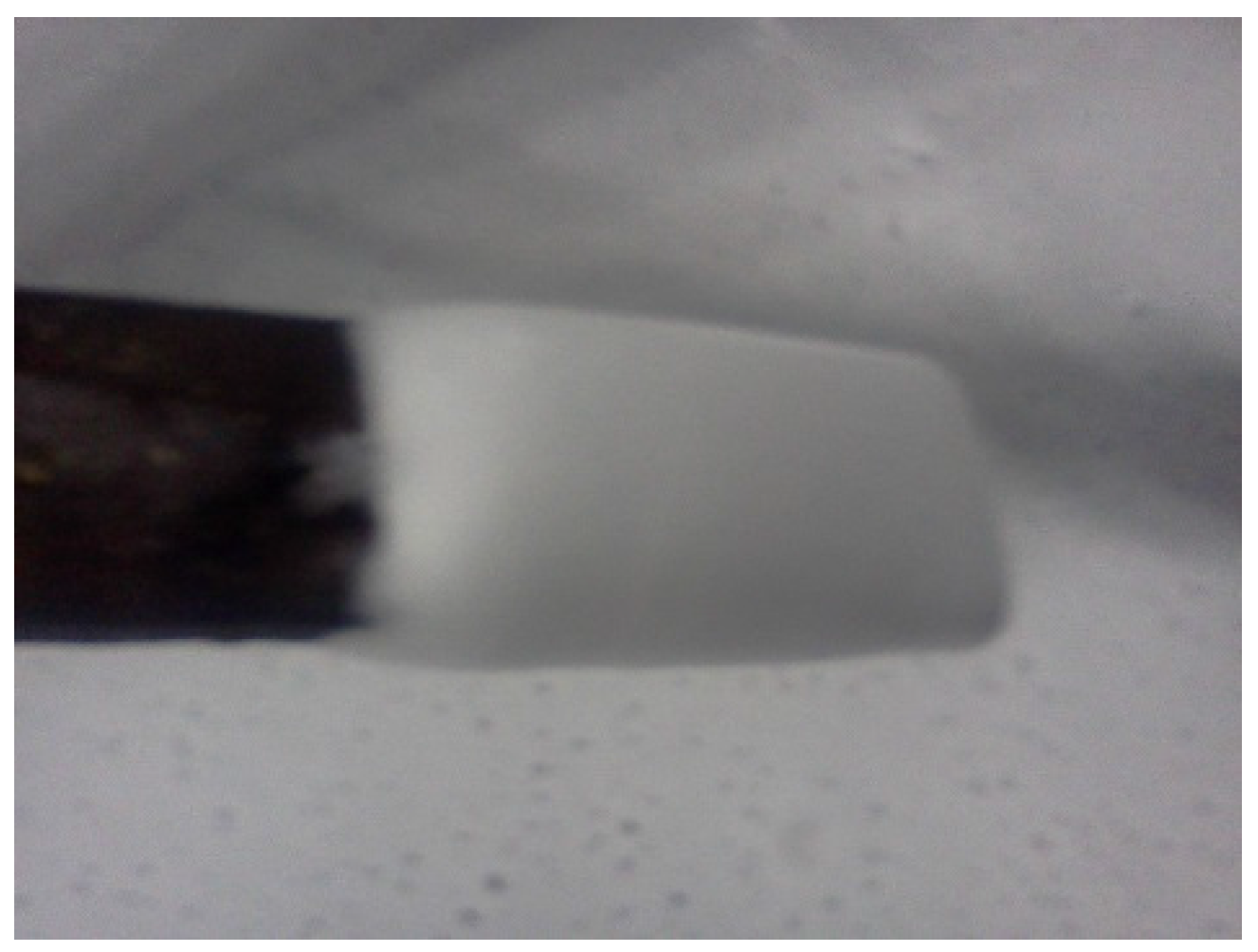
Figure 5 respectively show the shape of the discharging compressed air foam and the experimental results of the thermocouple and the heat flux at a mixing ratio of the air-to-aqueous foam solution of 1:4, an AFFF of 3%, and a discharge flow rate of 200 L/min. As shown in
Figure 4, given that the air (20%) and foam (80%) comprise the compressed air foam of specimen I, the particles of the compressed air foam are relatively coarse-grained and stiff.
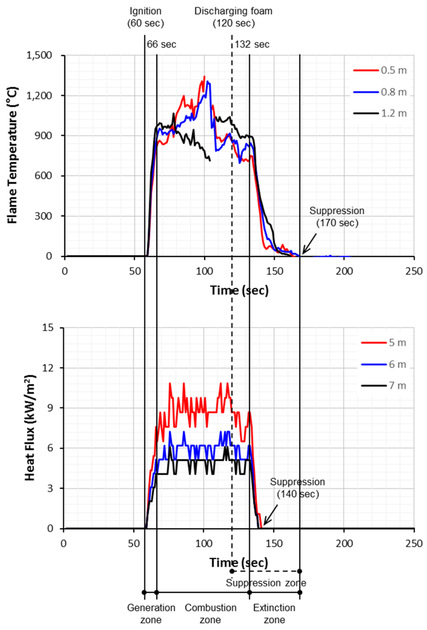
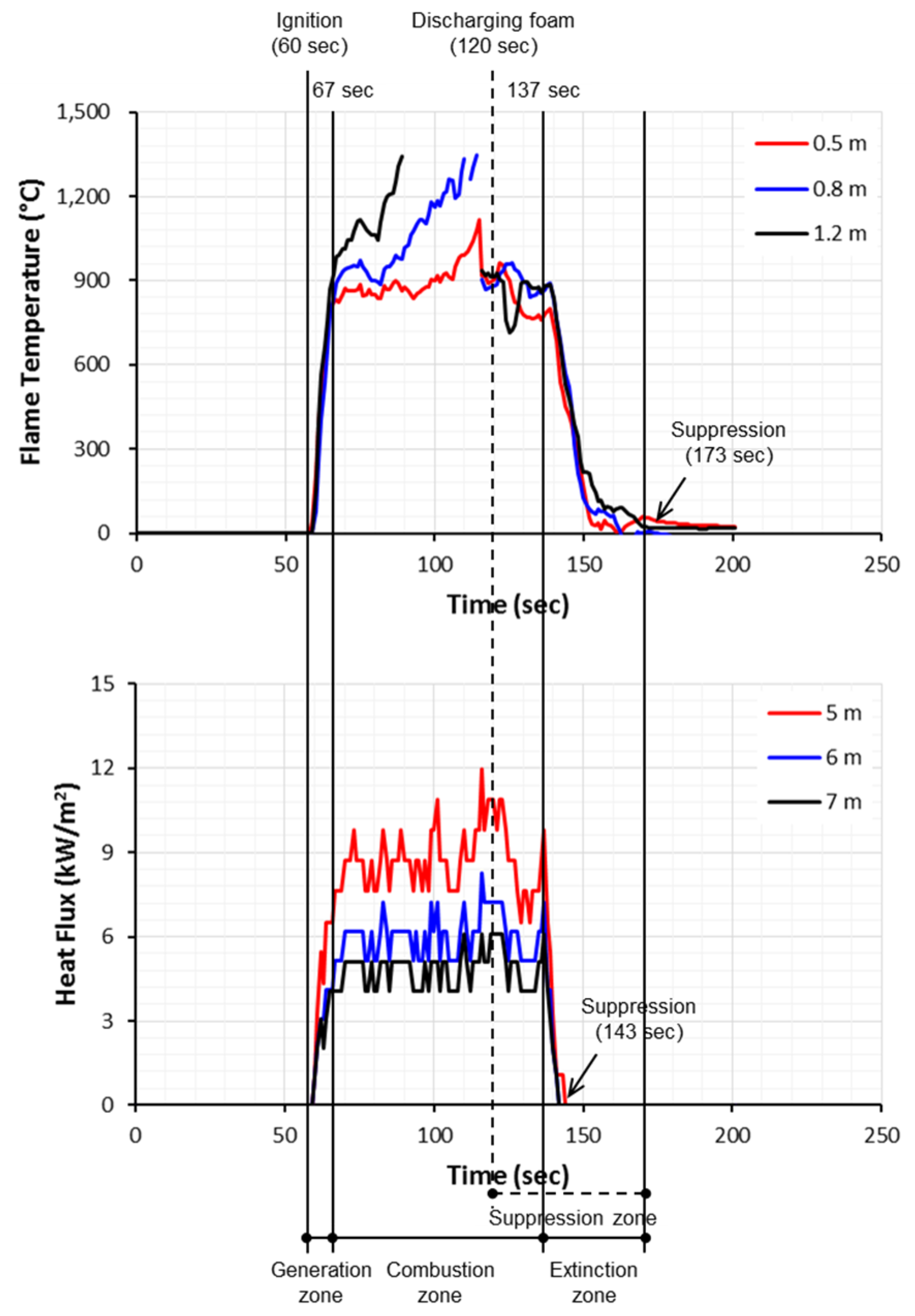
The relationship between the flame and time can be classified into the following three phases: (i) a generation zone in which the flame temperature and the heat flux increased continuously and simultaneously after ignition; (ii) a combustion zone which maintained the flux within a particular range; and (iii) an extinction zone in which the flame temperature and the heat flux decreased after the combustion zone, with the flame then being eliminated entirely (see
Figure 5).
From the measured results of the thermocouple, the flame lasted for a total time of 60 s to 170 s, from the ignition to when it was completely eliminated. It was found that the flame continued for approximately 50 s, except for the preliminary combustion time of 60 s out of the total combustion time of 110 s (see
Figure 6). Meanwhile, the results of measurements of the intensity of the heat flux started at 56 s, and the temperature of the flame suddenly decreased at 136 s. Thus, the measured time of the radiant intensity was 21 s excluding the preliminary combustion time of 60 s. It was determined that the vertical temperature of the thermocouple and the horizontal radiant intensity of the fire model provide evidence of the difference in the measured times due to the different measured locations and the different measured distances.
4.2. Specimen II
Figure 6 and
Figure 7 show the shape of the discharging compressed air foam and the experimental results of the thermocouple and the heat flux under a mixing ratio of the air-to-aqueous foam solution of 1:7, with the AFFF of 3%, and at a discharge flow rate of 200 L/min, respectively. Particles of the compressed air foam with the air-to-aqueous foam solution of 1:7 with air of 12.5% are small and disordered since the air to be included to the compressed air foam is relatively smaller in comparison with that of the air-to-aqueous foam solution of 1:4 (see
Figure 4 and
Figure 6). The measured results of the vertical thermocouple for the fire model are shown in
Figure 7. The flame was measured from 70 s and was cleared in 160 s. In other words, the flame duration is 90 s. Eventually, the net fire suppression time excluding the preliminary combustion time of 60 s was about 30 s. The average temperature of the flame was 989 °C.
As shown, the results of the intensity of the heat flux of the flame in
Figure 7 was observed for 70 s, from 148 s to 218 s. Its net measured time to the exclusion of the preliminary combustion time was 18 s. The measured values of the radiant intensity for which the horizontal distances were 5 m, 6 m, and 7 m away from the center of the flame were recorded as 5.09 kW, 6.19 kW, and 8.7 kW, respectively.
4.3. Specimen III
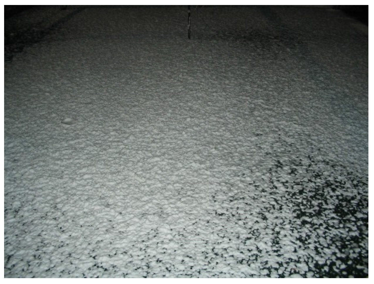
Figure 8 and
Figure 9 respectively illustrate the shape of the discharging compressed air foam and the experimental results of the thermocouple and the heat flux at a mixing ratio of the air-to-aqueous foam solution of 1:10, with the AFFF of 3%, and at a discharge flow rate of 200 L/min. The compressed air foam of this specimen includes the given air of 9.1% and foam of 90.9%. As the amount of given air is the smallest throughout the specimens of this study, the particles of the compressed air foam are too sloppy. The ignition time of the flame started at 75 s, and the flame was eliminated in 180 s. The net fire suppression time, which excludes the preliminary combustion time of 60 s, by the discharged compressed air foam was 45 s.
The intensity of the heat flux obtained from the experimental results was observed from 75 s to 160 s. Its total measured time was therefore 85 s. This includes the preliminary combustion time of 60 s and the net fire suppression time of 25 s.
Table 3 summarizes the experimental results of the specimens. Taking the experimental results together, the fire suppression time for the fire model with the mixing ratio of the air-to-aqueous foam solution of 1:4 is short compared to the fire suppression time with the mixing ratio of the air-to-aqueous foam solution of 1:7, while the fire suppression time for the fire model with the mixing ratio of the air-to-aqueous foam solution of 1:10 was increased. It was considered that the fire-extinguishing agent cannot penetrate into the flame, because the discharged foam that is manufactured to increase the mixed amount of compressed air in the compressed air foam becomes light.
5. Discussion
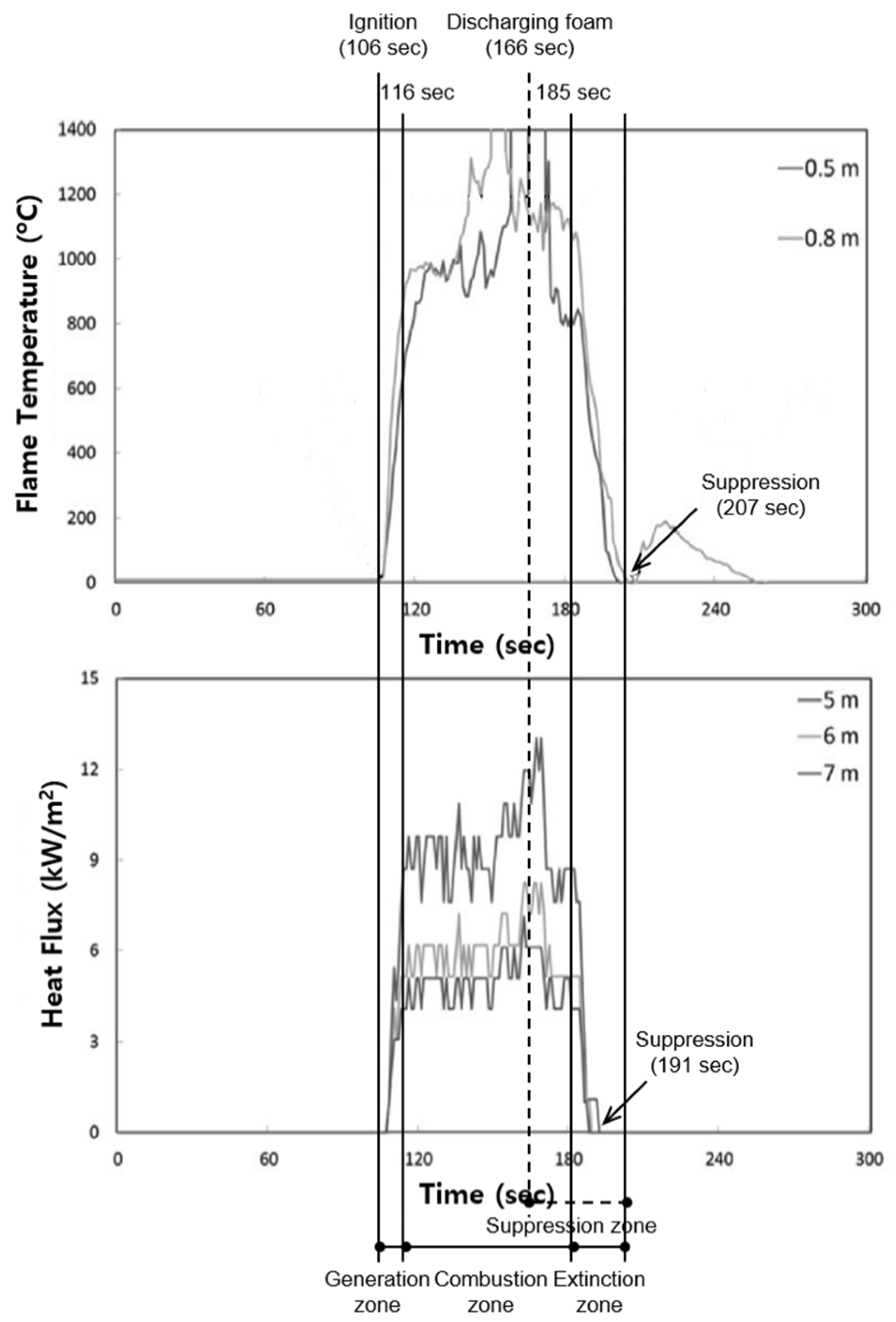
In this section, in order to examine the relative performance of the compressed air foam compared to the other fire-extinguishing agents, a synthetic surfactant type of foam developed and applied in Korea was assessed.
Table 4 summarizes the general material properties for the synthetic surfactant foam of 3%. These contents satisfied limited conditions regulated in the Korean specification [
10]. In this study, the discharging performance was not investigated because the fire-extinguishing agent through the Korean approved process was used. A specimen for which the mixing ratio of the synthetic surfactant foam of 3% and compressed air was 1:4 was used in the experiment. The discharged foam was released at a speed of 200 L/min. The experimental results are shown in
Figure 10.
In the measured result of the thermocouple, the flame is ignited in 106 s and is maintained to 207 s such that the total fire suppression time is 101 s. If the preliminary combustion time of 60 s is excluded from the total fire suppression time, the net fire suppression time is 41 s. On the other hand, from the results of the intensity of the heat flux, the flame is first caught at 106 s and is eliminated at 191 s. It was concluded that the net fire suppression time is 25 s.
Therefore, as the measured result of the heat flux of the flame is shorter than that of the AFFF, it was confirmed that the synthetic surfactant foam is better for subduing an actual fire. However, the measured result for the thermocouple under the same discharge condition showed that the fire suppression time of the AFFF of 3% is seven s faster. It was determined that flowing and aqueous film phenomena arise when the manufactured foam covers the surface of the oil, affecting the fire-extinguishing performance.
6. Summary and Conclusions
In this experimental study, a fire-extinguishing performance evaluation of a compressed air foam system was conducted with different mixing ratios of the air-to-aqueous foam solution with the AFFF of 3% and while discharging the foam at a speed of 200 L/min. A summary of the findings and a conclusion are given below.
- (1)
The expansion ratio and the 25% drainage time by the CAFS showed excellent performance compared to the GAMS. From these characteristics of the foam by the fire-extinguishing system, it can be found that the fire-extinguishing performance by the CAFS is better than the GAMS on oil fires. Moreover, an economic effect can be expected because there is an advantage to maximizing efficiency by minimizing water usage.
- (2)
The compressed air foam system with the air-to-aqueous foam solution of 1:4 showed a net fire suppression time of 34 s in the results measured by the thermocouple and a net fire suppression time of 21 s in the measured results obtained from the heat flux.
- (3)
The compressed air foam system with the air-to-aqueous foam solution of 1:7 showed a net fire suppression time of 30 s in the results measured by the thermocouple and a net fire suppression time of 18 s in the measured results obtained from the heat flux.
- (4)
The compressed air foam system with the air-to-aqueous foam solution of 1:10 showed a net fire suppression time of 45 s in the results measured by the thermocouple and the net fire suppression time of 25 s in the measured results obtained from the heat flux.
- (5)
In conclusion, it was found that the fire-extinguishing performance of the compressed air foam system with the air-to-aqueous foam solution of 1:7 and with aqueous film-forming foam of 3% at an identical flow rate of the discharging foam at a speed of 200 L/min is most effective.
- (6)
It was confirmed that the net fire suppression time by the compressed air foam system with the air-to-aqueous foam solution of 1:4 with the synthetic surfactant foam of 3% and at a flow rate of the discharging foam at a speed of 200 L/min as obtained from both the thermocouple and the heat flux is shorter than that with the AFFF of 3%.
Acknowledgments
This work was supported by the Incheon National University Research Grant in 2011.
Author Contributions
In this paper, the overall experimental plan in order to investigate the fire-extinguishing performance of the CAFS was prepared together by Dong-Ho Rie and Jang-Won Lee as a co-first author. The manuscript was written by Seonwoong Kim.
Conflicts of Interest
The authors declare no conflict of interest.
References
- Asselin, J.P.; Crampton, G.P.; Kim, A.K.; Richard, J.K. Compressed-Air Foam Fixed-Pipe Fire Suppression Systems. Fire Protect. Eng. 2007, 3, 1–10. [Google Scholar]
- Lim, W.S.; Sakong, S.H.; Jeong, J.H.; Nam, J.S.; Nam, D.G.; Na, Y.U.; Park, K.H. A Study of Establishment on the Compressed-Air Foam System. In Proceedings of the Korean Institute of Fire Science and Engineering Fall Conference, Jeonju-si, Korean, 10 November 2011; pp. 506–509.
- Magrabi, S.A.; Dlugogorski, B.Z.; Jameson, G.J. A comparative study of drainage characteristics in AFFF and FFFP compressed-air fire-fighting foams. Fire Saf. J. 2002, 37, 21–52. [Google Scholar] [CrossRef]
- Lee, J.-W.; Lim, W.-S.; Kim, S.-S.; Rie, D.-H. A Study on Fire Extinguishing Performance Evaluation of Compressed Air Foam System. J. Korean Inst. Fire Sci. Eng. 2012, 26, 73–78. [Google Scholar] [CrossRef]
- Feng, D. Analysis on Influencing Factors of the Gas-liquid Mixing Effect of Compressed Air Foam Systems. Proced. Eng. 2013, 52, 105–111. [Google Scholar] [CrossRef]
- Kim, A.K.; Crampton, G.P.; Asselin, J.P. A Comparison of the Fire Suppression Performance of Compressed-Air Foam and Foam-Water Sprinkler System for Class B Hazards. Natl. Res. Counc. Can. 2004, 2–25. [Google Scholar] [CrossRef]
- Cheng, J.; Xu, M. Experimental Research of Integrated Compressed Air Foam System of Fixed (ICAF) for Liquid Fuel. Proced. Eng. 2014, 71, 44–56. [Google Scholar] [CrossRef]
- Kim, A. Evaluation of the Fire Suppression Effectiveness of Manually Applied Compressed-Air-Foam (CAF) System. Fire Technol. 2012, 48, 549–564. [Google Scholar] [CrossRef]
- Korean Fire Institute (KFI). KFIS 045: Approved Standard for Compressed Air Foam System; Korean Fire Institute (KFI): Yongin-si, Korea, 2011. [Google Scholar]
- National Emergency Management Agency (NEMA). Approval of Type and Test Methods for Fire Extinguisher Agent: Code 2015-68; National Emergency Management Agency (NEMA): Seoul, Korea, 2015. [Google Scholar]
- Underwriters Laboratories (UL). Standard for Safety for Foam Equipment and Liquid Concentrates: UL 162; Underwriters Laboratories (UL): Northbrook, IL, USA, 1999. [Google Scholar]
- National Fire Protection Association (NFPA). NFPA 11: Standard for Low-, Medium-, and High-Expansion Foam; National Fire Protection Association (NFPA): Quincy, MA, USA, 2005. [Google Scholar]
- National Emergency Management Agency (NEMA). Standard for Performance Certification and Product Inspection of Foam-Extinguishing-Agent Proportioner: Code 2012-81; National Emergency Management Agency (NEMA): Seoul, Korea, 2012. [Google Scholar]
© 2016 by the authors; licensee MDPI, Basel, Switzerland. This article is an open access article distributed under the terms and conditions of the Creative Commons Attribution (CC-BY) license (http://creativecommons.org/licenses/by/4.0/).


