Article

Application of a New Anchorage towards the Flexural Strengthening of RC Rectangular Beams with External Steel Tendons

1
College of Engineering, Sungkyunkwan University, 2066, Seobu-Ro, Jangan-Gu, Suwon-Si, Gyeonggi-Do 16419, Korea
2
Department of Technology Education, Chungnam University, 99 Daehak-ro, Yuseong-gu, Daejeon 34134, Korea
3
Department of Civil and Environmental Engineering, Sungkyunkwan University, 2066, Seobu-Ro, Jangan-Gu, Suwon-Si, Gyeonggi-Do 16419, Korea
*
Author to whom correspondence should be addressed.
Appl. Sci. 2016, 6(5), 119; https://doi.org/10.3390/app6050119
Submission received: 8 January 2016 / Revised: 14 April 2016 / Accepted: 15 April 2016 / Published: 25 April 2016

Abstract

:
To strengthen concrete beams, a new anchorage was proposed, and its performance was evaluated in this study. Seven concrete beams were manufactured and flexurally loaded with displacement control up to the failure point. As important test variables, the anchorage type (new/conventional) and the prestress levels in the steel rebar (0, 50, and 100 kN) were selected. To investigate the strengthening effects based on these test variables, the deflection, strain, and failure mode were recorded, and then the load, ductility index, and energy ratio were analyzed. Test results showed that the newly proposed end anchorage had better strengthening effects and a greater inelastic energy than the conventional end anchorages.

1. Introduction

Concrete structures deteriorate as they age [1]. Therefore, maintenance techniques to extend the lifespan of concrete structures have been constantly developed [2]. Nevertheless, problems with concrete structures continue to occur. Typical problems include corrosion of the internal steel rebar [3], alkali–aggregate reactions, and carbonation of the concrete [4,5,6]. Many strengthening methods have been adopted to improve the performance of deteriorated concrete structures, including the use of sole plate reconstruction, externally bonded (EB) steel plates, externally bonded fiber-reinforced polymers (EB FRPs), and external steel tendons [1]. Among these, the use of external steel tendons is the most common [7], because they offer good applicability and high strengthening efficiency. In addition, external steel tendons are easy to analyze structurally, economically viable [8], and do not impose an additional load on the beams. Furthermore, they are easy to install, require a short construction time [9], and do not interfere with the maintenance of the structure after installation. Furthermore, the degree of strengthening can be adjusted by controlling the prestress levels in the external tendon [10].
However, the use of external steel tendons may result in problems if the anchorage system fixing the prestressing tendons is not providing sufficient load resistance [11,12,13]. A further problem is the wide range of anchorage systems. The majority of end anchorages used with external tendons are installed via premade lifting holes in the concrete beams or prestressed concrete girders. Lee et al. [14] conducted an experiment to examine the performance of three types of existing anchorages that are frequently used in structures. The results of their experiments identified several problems, such as cracking around the lifting hole, anchor bolts pull-out, and concrete delamination around the anchorage [15].
This study addresses a novel type of end anchorage as a means of overcoming the drawbacks associated with the conventional end anchorages. This newly proposed anchorage minimizes the use of stud anchors, which can damage reinforced and prestressed concrete beams. It is shaped in a way that allows it to efficiently transfer the prestress forces in an external steel tendon to a beam. To evaluate the performance of the new anchorage, it was compared with three types of conventional anchorages by subjecting them to a static loading test.

2. Experimental Section
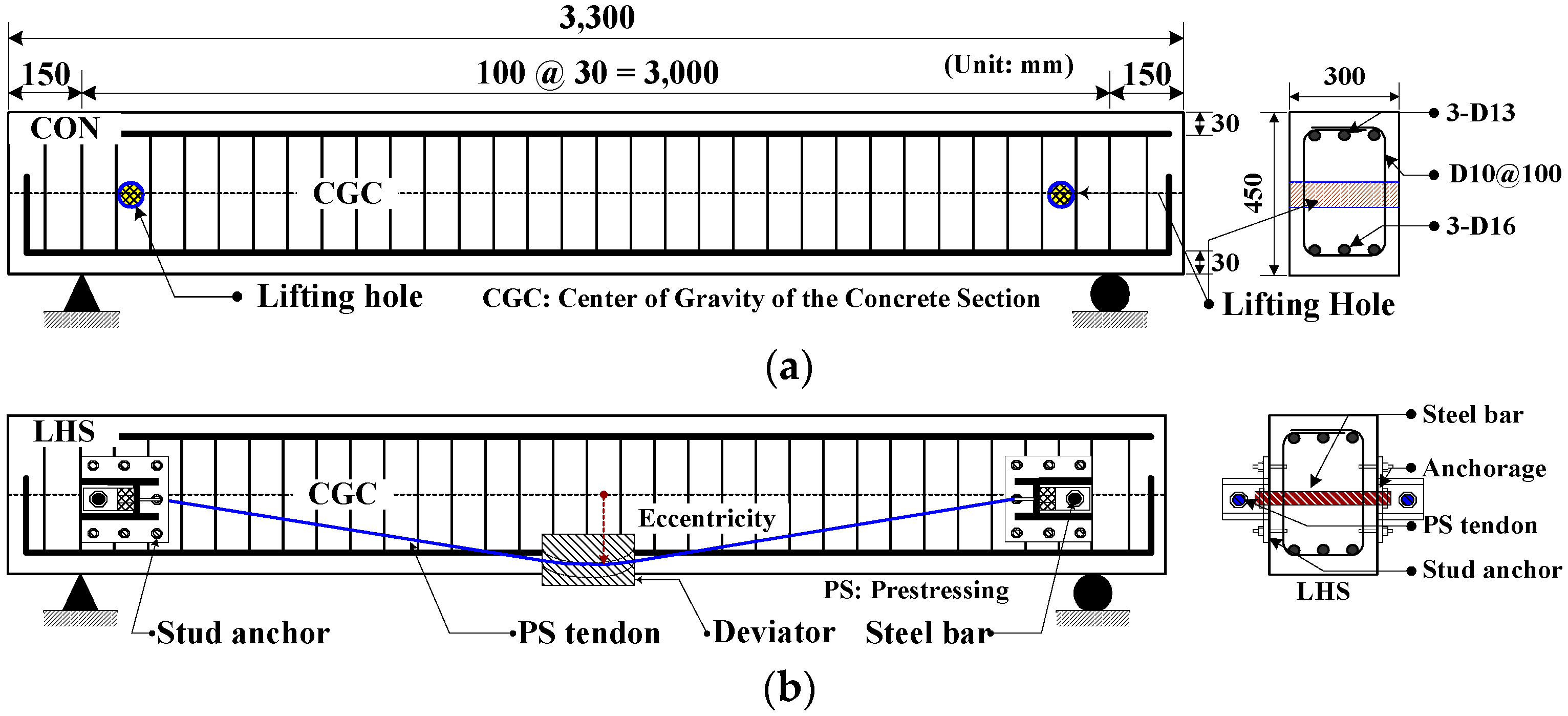
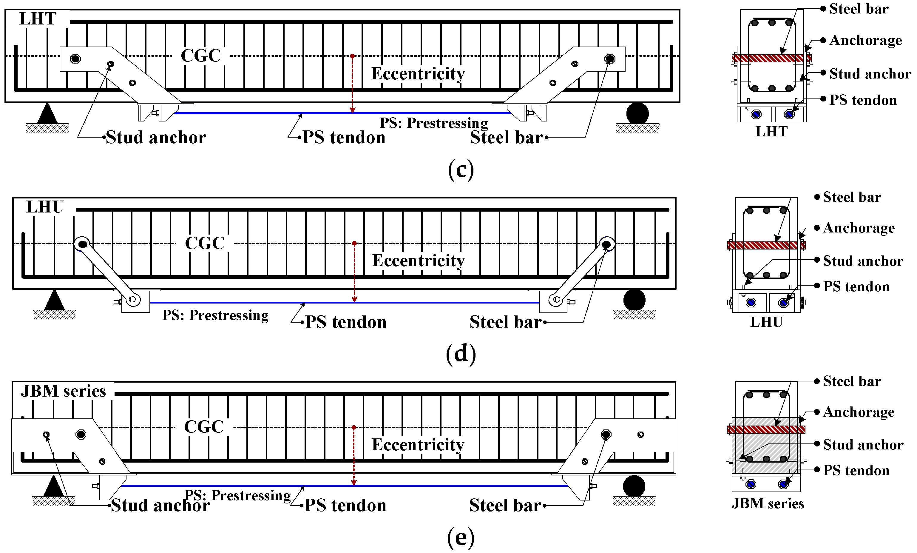
2.1. Test Variables

Experiments were conducted on seven beams. One beam was a control beam with no end anchorages, three others had different types of conventional anchorages, and the remaining three had the proposed end anchorage. For all of the pre-stressed beams, the bending moments, by applying the prestress force, were identical at the mid-span of the beams. This approach allowed us to make a direct comparison of the prestressed strengthened beams. Because the newly proposed anchorage also uses a lifting hole, the prestressing force applied to the steel rebar was regarded as a test variable. Table 1 outlines the test variables.

2.2. Material Properties

Various compressive strengths were selected depending on the applications of the structures. In South Korea, infrastructure projects, such as bridges, usually use concrete with a compressive strength of 40 MPa. To simulate the degradation in the strength of a concrete structure that requires strengthening, ready-mixed concrete with a design strength of 35 MPa was used to produce the beams. Three cylinders (100 mm diameter × 200 mm height) were used for the compression test. The measured average compressive strength proved to be 30 MPa. For the internal steel rebar used in the beams, D10 (9.5 mm in diameter), D13 (12.7 mm in diameter), and D16 (15.9 mm in diameter) deformed bars were used. The average yield strength and ultimate strength of these bars are 450 and 620 MPa, respectively. The steel rebar mounted in the lifting hole had a diameter of 34 mm, a length of 400 mm, and an ultimate tensile strength of 828 kN. The steel tendon used for prestressing had a diameter of 12.7 mm and an ultimate tensile strength of 183.4 kN. The anchorages were manufactured using steel plates 12 to 20 mm thick with an average yield strength of 314 MPa and an average tensile strength of 530 MPa. Stud anchors with a diameter of 18 mm were used to install the anchorages, and the allowable tensile and shear strengths of these anchors were 27 and 40 kN, respectively. The Young’s modulus of steel materials used in this study was 200 GPa. A round plastic pipe with a 35 mm inner diameter and a 37 mm outer diameter was used to create a lifting hole in the concrete beam. The rupture strength of this pipe was 28 MPa. Epoxy resin with a tensile strength of 33.5 MPa and a bonding strength of 2.0 MPa was injected into the space between the anchorages and the concrete beams to provide greater adhesion. The above-mentioned material properties excluding the concrete were provided by the manufacturers.

2.3. Production of Beams

Seven concrete beams were manufactured. Each beam had a rectangular cross section of 300 mm (width) × 450 mm (height), and total and net spans of 3.3 and 3.0 m, respectively. The cover of the tensile part of the concrete was 30 mm thick for each beam. Concrete beams are typically designed as double-reinforced beams with more tension bars than compression bars. Therefore, for this experiment, the concrete beams were produced as doubly reinforced beams with more tension steel area than compression steel area. For the compression bars, three D13 deformed bars were used; for the tension bars, three D16 deformed bars were used. For the stirrups, D10 bars were placed at 100 mm intervals along the length of the beam. Plastic pipes with 35 mm inner diameter were used to create lifting holes. These pipes were fixed onto the shear steels before concrete pouring. Figure 1 shows the cross-sectional dimensions of the beam, and the internal and external reinforcing bars.
The anchorages installed at both ends of the beam to fix the external prestressing tendons must not have any performance problems until the beam is destroyed by both the force generated on the external prestressing tendons by the applied load, and the prestressing force. An examination of the load resistance mechanism of the end anchorages reveals that the shear generated by the pull of the external tendon is resisted by the shear capacity of the anchors used to fix the anchorage. An analytical investigation was conducted to evaluate the shear resistance capacity of the anchorages that were used in this experiment. Furthermore, the fixing specifications of each anchorage were determined to have the same shear resistance as these of the afore-mentioned investigation. The allowable shear resistance was calculated as 210 kN.
In the case of the existing anchorages, the force generated by the prestress force and the applied load is resisted by the shear of the steel rebars and stud anchors set in the lifting holes. One steel rebar and eight stud anchors were used to fix each anchorage and concrete beam. On the other hand, for the anchorage proposed in this study, the force generated by the prestress force and the applied load is resisted by one steel rebar, six stud anchors, and the steel plates comprising the anchorage.
The threaded steel rebar was fit into the premade hole for lifting the steel concrete beam, and was then fixed with fastening nuts. On the other hand, the stud anchors were mounted by making holes in the concrete, inserting anchor bolts, and fastening anchor nuts. Figure 2 shows the dimensions and shapes of the end anchorages mounted on the beam to fix the external steel tendons.
It should be noted that the proposed new anchorage is a natural extension of the anchoring schemes of the anchorages that were proposed in previous studies [14,15], provided the steel concrete beam has a free end. Therefore, this anchoring scheme cannot be applied if there is continuity of the steel concrete beams over the support, such as with the continuous beam.

2.4. Prestressing

In an externally prestressed concrete structure, prestress is introduced by extending the external tendons, and then fixing them against the concrete. Therefore, a prestressing system must include methods of extending a tendon and fixing it onto concrete.
The prestress systems that were used in this study are classified into two types: one for the external steel tendons and the other for the steel rebars set in the lifting holes. The prestress system for the external steel tendons consists of a mono wedge anchorage and a hydraulic jack. The mono wedge anchorage fixes the steel tendons onto the end anchorages, whereas the hydraulic jack generates a tensile force in the steel tendons. A jacking force was applied to the external steel tendons using these devices. On the other hand, the prestress system for the steel rebars set in the lifting holes consists of an anchor plate, anchor nut, and a torque wrench. The anchor plate and anchor nut fix threaded steel rebars onto the lifting holes, whereas the torque wrench generates a tensile force in the steel rebars. These devices were used to generate a jacking force in the steel tendons inside the lifting holes.
To provide the same reinforcement effect, the same moment must be generated by the prestressing at the mid-span of the prestressed beam. The moment caused by prestressing is calculated by multiplying the prestress force introduced by the eccentricity. Eccentricity is defined as the distance at any point in the span between the center of gravity of the external steel tendon and that of the concrete section. As shown in Table 1, the same prestress force of 95 kN was introduced to two external tendons for every prestressed beam, with the exception of the beam that used the conventional anchorage Type I (LHS beam), and the tendon had a 280 mm eccentricity. However, a double prestress force of 190 kN was introduced to two external tendons of the LHS beam, because its eccentricity is half that of the other beams. To evaluate the effects of the prestressing levels introduced to the steel rebar on the behavior of the beam, 0, 50, and 100 kN prestress forces were considered.

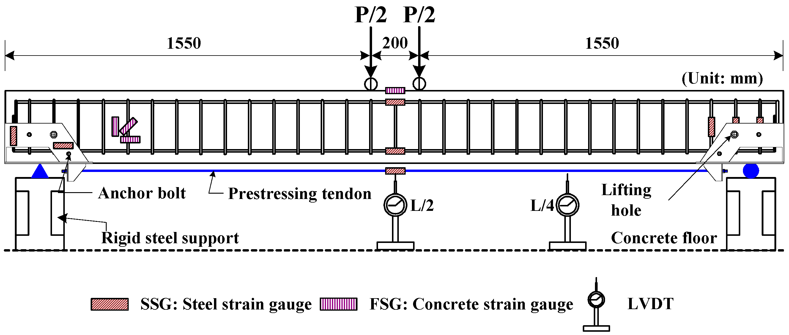
2.5. Loading and Measurements

For the prestressed beams, a four-point bending test was performed until failure using a 1000 kN UTM (Universal Testing Machine, MTS Systems Corporation, Minnesota, MN, USA) and a loading rate of 1 mm/min. To measure the strain behaviors of the compression bars, tension bars, and the prestressing tendon, strain gauges were attached to the mid-span where the maximum moment occurs, as shown in Figure 3. To measure the deflection of the beams, which is the degree of bending caused by the load, two linear variable differential transformers (LVDT, Tokyo Sokki, Tokyo, Japan) were installed at the mid-span (L/2) and the quarter-span (L/4) points. Furthermore, to record the anchorage strain resulting from the increased load, multiple strain gauges were attached to the anchorages. The data recorded by the strain gauges and LVDTs were collected using an EDX-1500A data logger (Kyowa, Tokyo, Japan), and then analyzed on a personal computer.

3. Losses in Prestressed External Tendon

The prestress forces were recorded using the strain gauges installed at the center of one external steel tendon for each beam. To introduce an accurate prestress force, the steel tendons were rejacked several times until the target prestress strain was reached. The prestress strains were recorded on the day when prestressing was introduced and immediately before the flexural tests (1–2 days after introducing prestressing). The target and measured prestress strains are outlined in Table 2. The prestress forces were obtained by multiplying the modulus of elasticity and the cross-sectional area of the steel tendon by the measured strain. Furthermore, the effective prestressing forces in the prestressed external tendons at the mid-span ranged from 44.3 to 88.0 kN. As can be seen in Table 2, the new proposed anchorage in this study showed a smaller loss compared with the conventional anchorages. Furthermore, the higher the levels of prestress on the steel rebars placed in the lifting holes, the lower the loss, even with slight variation. The maximum reduction in the prestress loss occurred in the LHS beam, which was approximately 7.4% of the initial prestress strain.

4. Test Results and Discussion
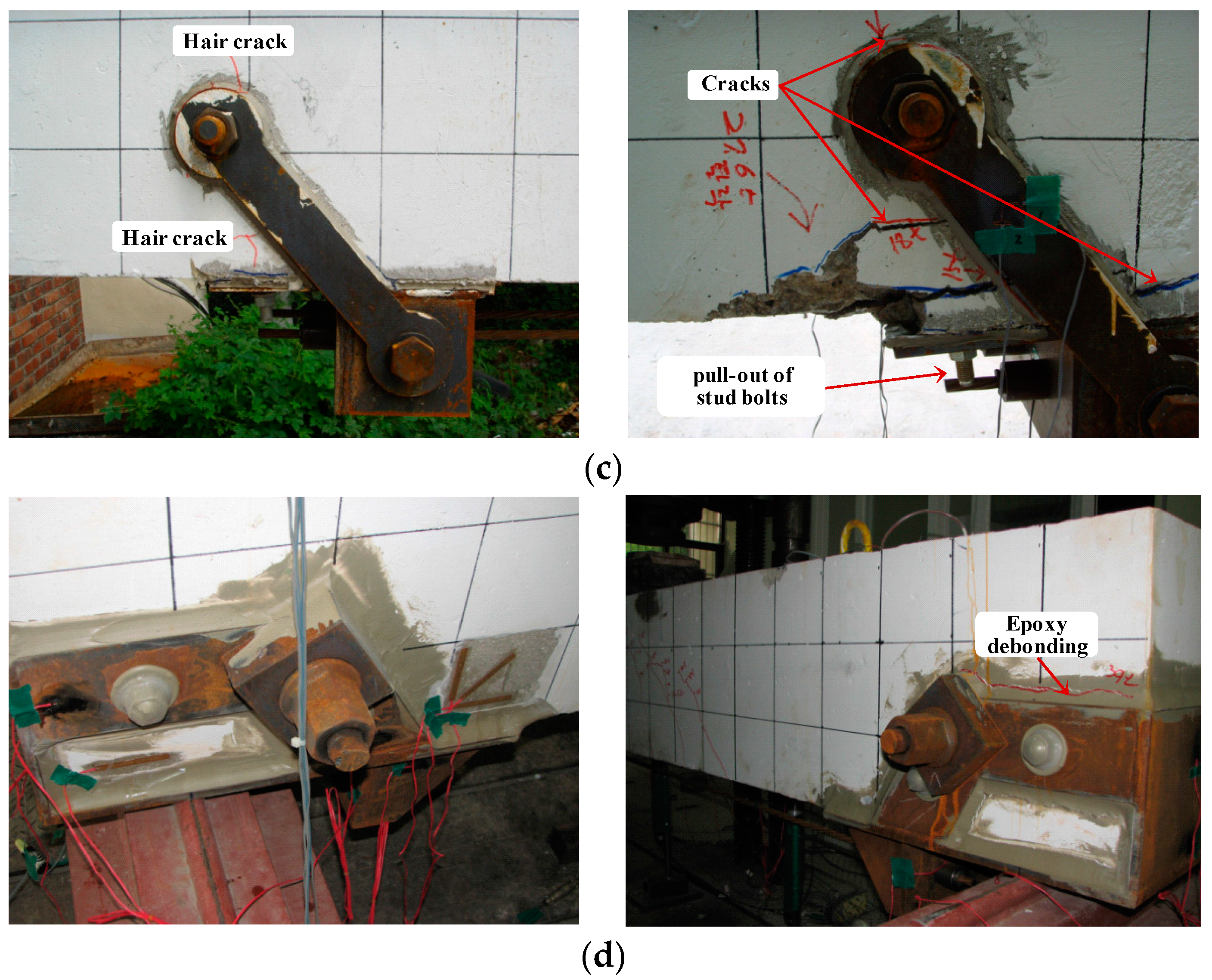
4.1. Failure Modes

Pictures of the anchorages installed in the experimental beams, before and after the flexural test, are shown in Figure 4. The control beam, which was a non-prestressed beam, failed at the mid-span when the top of the concrete was crushed after the tension bar yielded. This failure is typical of a reinforced concrete beam and, thus, it was expected, because the control beam had a steel ratio that was less than the balanced steel ratio. One of the beams (LHS), was prestressed with a conventional anchorage and a prestressing tendon, exhibited considerable cracking around the anchorage as the load was increased after the yielding of the tension bar, while the epoxy used to fill the space between the anchorage and the concrete was expelled (Figure 4a). On the other hand, the two remaining beams that used the conventional anchorages Type II and Type III (LHT beam and LHU beam) exhibited considerable cracking around the anchorage after the yielding of the tension bar. The pull-out of a few stud bolts led to local failure of the anchorage and, thus, failure of the beam (Figure 4b,c). In the beams that were prestressed with a prestressing tendon and fixed using the proposed anchorage (JBM series), only the epoxy was expelled, and neither cracking around the anchorage nor pull-out of the stud bolts was observed (Figure 4d).

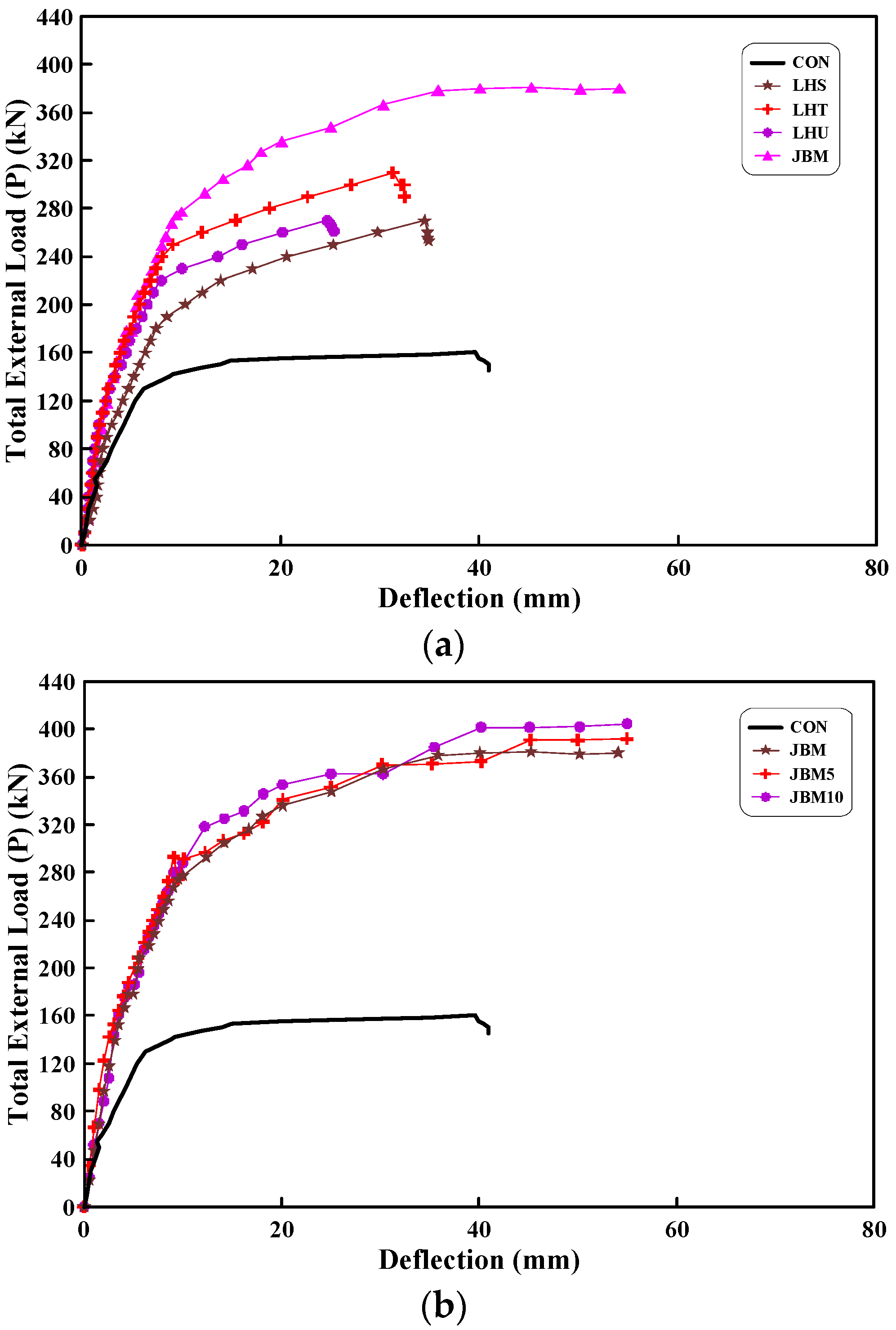
4.2. Load-Deflection Relationship

Table 3 lists the cracking load, yield load, and ultimate load of the prestressed beams measured at the mid-span. The cracking, yield, and ultimate loads are the external total loads (P) when the flexural crack starts to occur, the tension steel starts to yield, and the beam starts to fail, respectively. In addition, this table shows the yield of the prestressed beams and the rate of increase in the ultimate load relative to the control beam, as well as the effects of the prestress force introduced to the steel rebar mounted on the lifting hole.
The load–deflection curves until the point of failure of the tested beams are shown in Figure 5. The load–deflection curves of the prestressed beams, excluding the control beam, exhibit three straight lines, which correspond to the cracking of the concrete, the yield of the tension bar, and the failure.
As shown in Figure 5a, the yield and ultimate loads of the beams, reinforced with a prestressed tendon and fixed with a conventional anchorage, increased by 41% to 88% and 63% to 86%, respectively, as compared with those of the control beam. However, the yield and ultimate loads of the beams with the newly proposed anchorage increased by 110% to 148% and 132% to 140%, respectively. This difference results from the more efficient transmission of the tension force in the prestressing tendon by the proposed anchorage as compared with a conventional anchorage. The conventional anchorages incurred problems such as the stud anchors pull-out, cracking around the anchorage, and local failures between the beam and the anchorage. In contrast, the proposed anchorage did not exhibit such problems, because of its efficient load transmission structure.
The effects of the changed prestress forces, introduced to the steel rebar, on the load–deflection behavior of the prestressed beams are shown in Figure 5b. Compared with the beams that used a non-prestressed steel rebar (JBM), the beams that used 5 kN and 10 kN prestressed steel rebar (JBM5 and JBM10, respectively) exhibited a moderate increase in their yield load of 7% to 14%, but only a small increase of 2% to 3% in the ultimate load. This can be attributed to the proposed anchorage and concrete beam being more closely adhered to each other, because of the existence of a prestressed steel rebar, which improved the transmission of the prestressing tendon’s tensile force on the concrete beam. In other words, the prestressing for the steel rebar was adjudged to have an influence on the tension steel to some degree, and to have delayed the yield of the tension steel. The ultimate load of the beams to which the proposed anchorage was applied was almost identical, regardless of the prestress levels introduced to the steel rebar, as shown in Figure 5b. This is because the failure of the beam was dominated by the yield of the prestressing tendon, rather than by the failure of the anchorage itself.

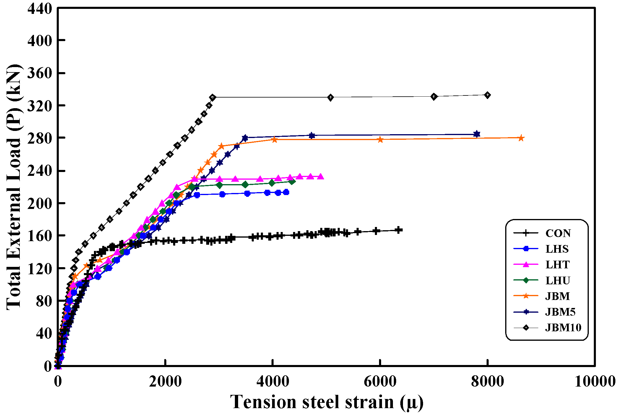
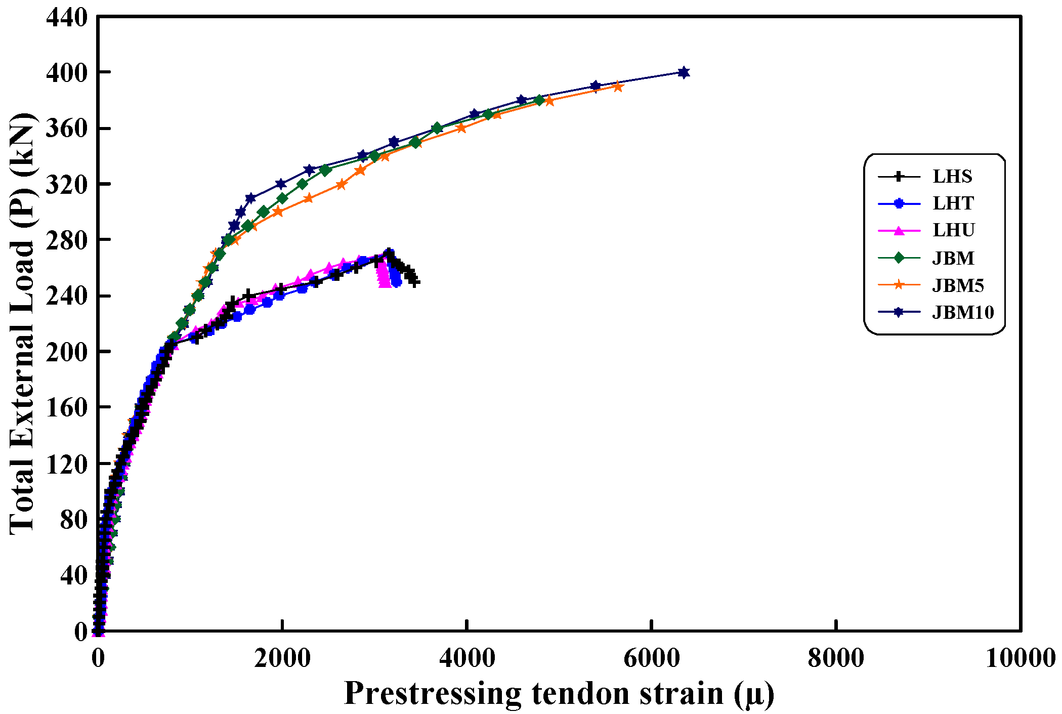
4.3. Strain Behavior

The strains measured through the strain gauges attached to the prestressing tendon and tension steel bar were compared as the load increased, as shown in Figure 6 and Figure 7. As shown, the strain expression mode increases continuously with the load.
Figure 6 shows how the strain in the tension bar changes as the load is increased. The strain at the mid-span of the beam increased sharply when the initial bending crack occurred; subsequently, it increased further with the load until it reached the yield strain. Furthermore, unlike the beams with conventional anchorages, the beams with the newly proposed anchorage exhibited tension strain prior to the load being increased.
Figure 7 shows that the strain in the prestressing tendon increased sharply as the load-sharing ratio of the prestressing tendon for the applied load increased after the yielding of the tension bar. Compared with beams with conventional anchorages, the prestressing tendon of a beam with the newly proposed anchorage exhibited strain until the load increased significantly. This is because the proposed anchorage continued to resist the load applied on the prestressing tendon until the ultimate condition, because of its efficient load transmission structure with a minimum number of stud anchors, and the improved shape of the anchorage itself.

5. Ductility

Ductility can be defined as the ratio of the ultimate deflection to the yield deflection. The concept of ductility corresponds to the nonlinear deformation of a structural member with no significant loss in load resistance until failure. Generally, concrete beams must have a certain degree of ductility to allow them to deform while not succumbing to brittle fracture. Furthermore, in the case of statically indeterminate structural members, ductility prevents local failures by redistributing the excess strain in one section to other sections. The ductility index is a typical measure of ductility.
The ductility index of the control beam was 10.45. As shown in Figure 8, the ductility indices of the prestressed beams were constant regardless of the applied anchorage type. The beams with conventional anchorages showed an average ductility index of 3.66, whereas the beams with the newly proposed anchorage showed an average ductility index of 3.76. These values are equal to approximately 37% of the ductility index of the control beam. The use of end anchorages and external prestressing tendons greatly decreases the ductility of the reinforced beam. The decrease in the ductility of the prestressed beam is caused by the domination of the applied prestress force over the plastic behavior of the prestressed beam.

6. Inelastic Energy

The energy in a concrete beam is generally divided into elastic and inelastic energy. When the load applied to a beam with elastic energy is removed, the beam tends to return to its original state. This is referred to as “elastic recovery”. The degree of elastic recovery indirectly indicates the degree of damage to the beam. However, the beam is permanently deformed if it is subjected to a load greater than the elastic limit. This permanent deformation is expressed as inelastic energy and is used as an indicator of the plastic behavior of a beam. In this study, the elastic and inelastic energies of each tested beam are defined as the area below the load-deflection curve up to the yield of the beam, and the area between the yield and failure of the beam, respectively.
From the viewpoint of stability, which indicates the safety of beams, prestressed beams must have a greater amount of inelastic energy. As shown in the bottom-right image in Figure 9, the ratio of the inelastic energy to the total energy is indicated, which shows the ratio of the dissipated inelastic energy to the total energy until the failure of the structure. The inelastic energy ratios were calculated based on this concept, and the results are shown in Figure 9. As shown, the inelastic energy ratios of the prestressed beams are smaller than that of the control beam. The average inelastic energy ratio of the beams with the conventional anchorages and those with the proposed anchorage are 78.3% and 85.7%, respectively. This difference was caused by the greater resistance of the proposed anchorage, relative to that of the conventional anchorage, to the plastic behavior of the prestressed beams.

7. Conclusions

In this study, prestressed beams were produced either using a newly proposed anchorage or existing anchorages. Experiments based on these beams were conducted to evaluate the bending behavior and performance of the anchorages. Seven concrete beams were manufactured. One was the control beam, while the others were prestressed beams. The following conclusions are drawn:
(1)
The beams that were prestressed with an external tendon showed significant increases in both their yield load and ultimate load compared with the control beam. In particular, the yield and ultimate loads of the beams with the newly proposed anchorage increased by 110% to 148%, and 132% to 140%, respectively, relative to the control beam. The increases at each load (yield and ultimate) are approximately twice as high as those of the conventional anchorages, indicating that the proposed anchorage has better reinforcing effects.
(2)
As increasing the prestress forces applied to the steel rebar mounted in the lifting hole, the yield and ultimate loads of the prestressed beams increased by 7% to 14%, and 2% to 3%, respectively. The incorporation of the prestressed steel rebar significantly affected the yield load of the beams, but had almost no effects on the ultimate load.
(3)
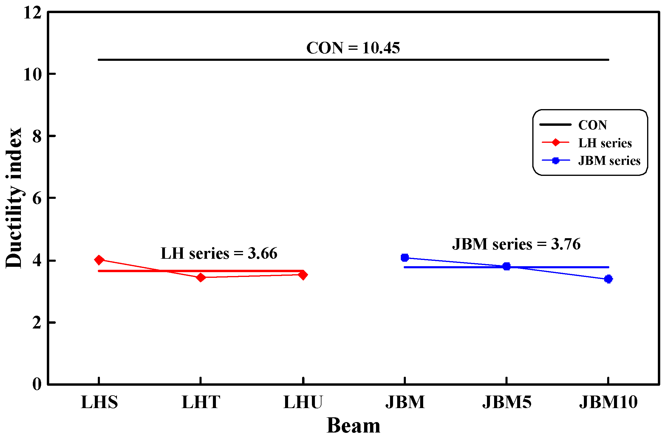
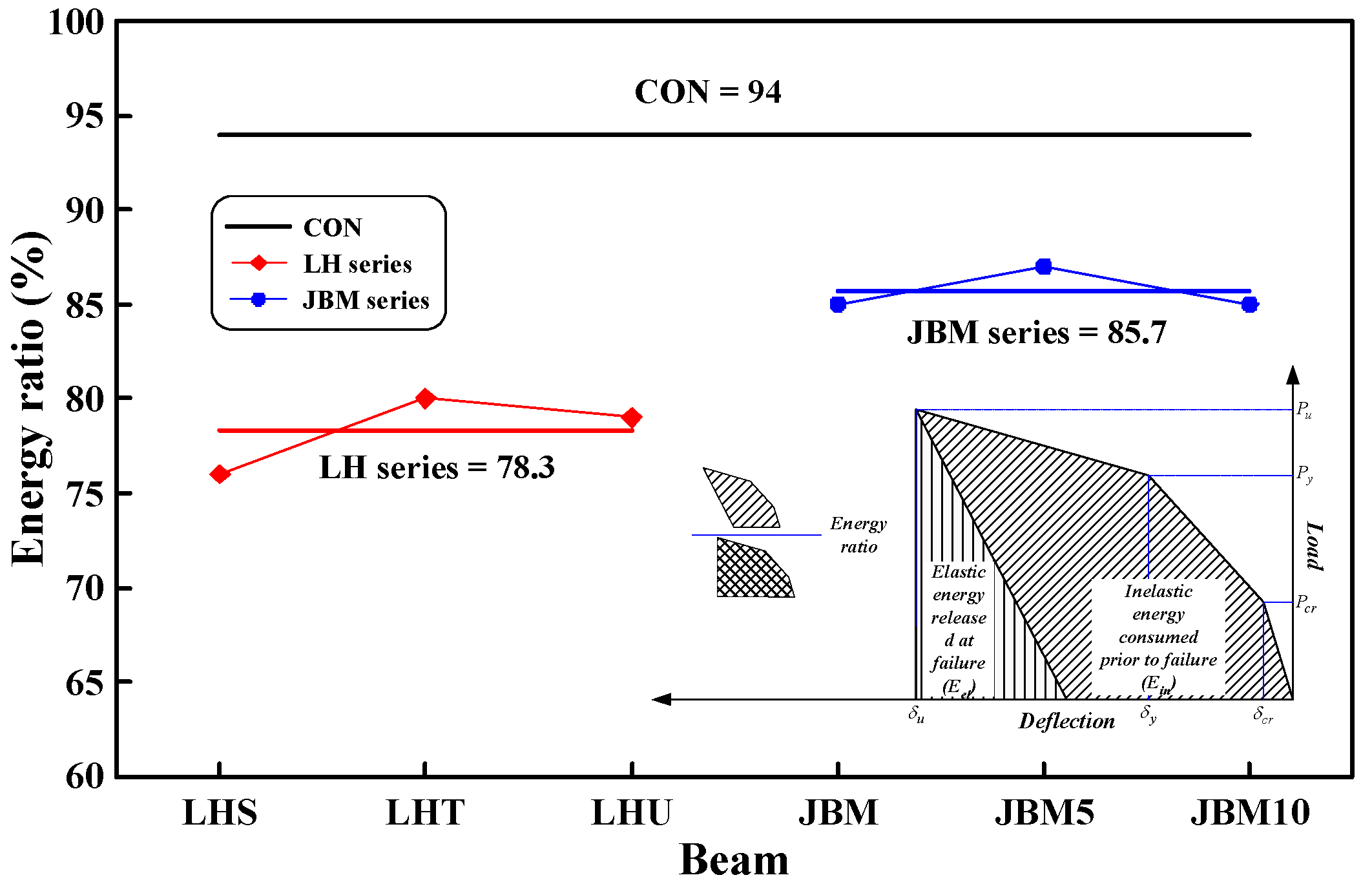
Compared with the control beam, the prestressed beams exhibited very low ductility. Furthermore, in the same way as for the ductility, the prestressed beams had a lower inelastic energy than the control beam. However, the beams using the newly proposed anchorage showed a higher inelastic energy than those with the conventional anchorage.
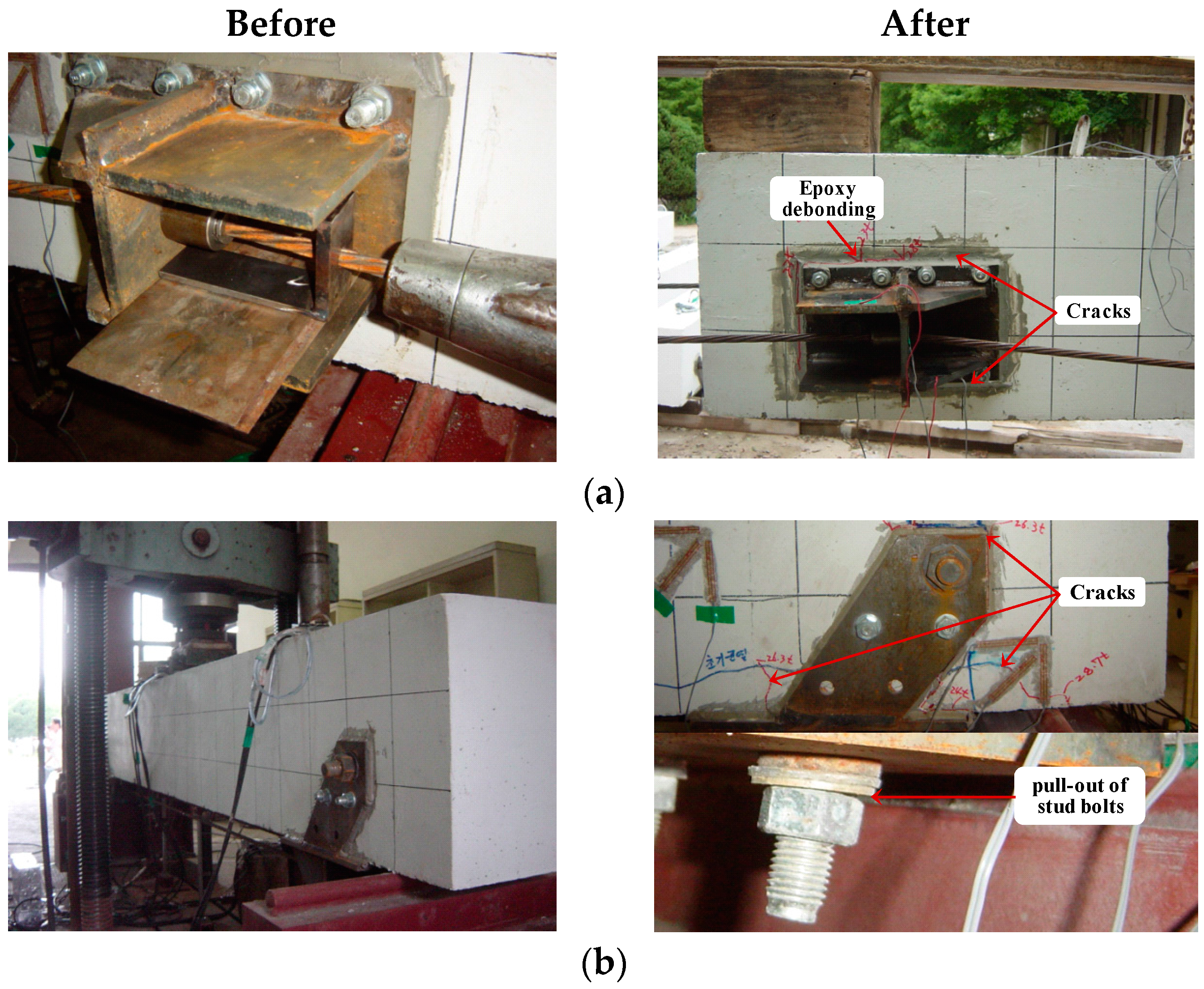
(4)
In the beams with the conventional anchorage, problems such as cracks around the anchorage, stud bolts pull-out, and local failure of the anchorage arose. However, the newly proposed anchorage exhibited no such problems, and instead, behaved stably at the ultimate load, with only the epoxy being expelled from the concrete. This was caused by the proposed anchorage having a structurally superior shape, which enables the efficient transmission of the prestress force.

Acknowledgments

This research was supported by the Basic Science Research Program of the National Research Foundation of Korea (NRF), funded by the Ministry of Education (2013R1A1A2059122).

Author Contributions

Sungnam Hong, Dooyong Cho and Sun-Kyu Park conceived and designed the experiments; Sungnam Hong performed the experiments; Dooyong Cho analyzed the data; Sun-Kyu Park participated in manuscript writing and revision. All authors collaborated on the interpretation of the results and on the preparation of the manuscript.

Conflicts of Interest

The authors declare no conflict of interest.

References

  1. Stewart, M.G.; Rosowsky, D.B. Time-dependent reliability of deteriorating reinforced concrete bridge decks. Struct. Saf. 1998, 20, 91–109. [Google Scholar] [CrossRef]
  2. Park, S.K.; Joe, S.I. Bridge Maintenance and Management; Il Kwang: Seoul, Korea, 2005. [Google Scholar]
  3. Song, G.; Shayan, A. Corrosion of Steel in Concrete: Causes, Detection and Prediction; ARRB Transport Research: Vermont South, Australia, 1998. [Google Scholar]
  4. L-Amoundi, O.S. Durability of reinforced concrete in aggressive sabhka environments. ACI Mater. J. 1995, 92, 236–245. [Google Scholar]
  5. Mien, T.V.; Stitmannaithum, B.; Nawa, T. Simulation of chloride penetration into concrete structures subjected to both cyclic flexural loads and tidal effects. Comput. Concr. 2009, 6, 421–435. [Google Scholar] [CrossRef]
  6. Hanjari, K.Z. Structural Behavior of Deteriorated Concrete Structures. Ph.D. Thesis, Chalmers University of Technology, Gothenburg, Sweden, 2010. [Google Scholar]
  7. Suntharavadivel, T.G.; Aravinthan, T. Overview of external post-tensioning in bridges. In Proceedings of the Southern Region Engineering Conference (SREC), Toowoomba, Australia, 15 October 2005.
  8. Naaman, A.E. Prestressed Concrete Analysis and Design, 3rd ed.; Techno Press 3000: Ann Arbor, MI, USA, 2012. [Google Scholar]
  9. Roger, A.D. Methods of Increasing the Live Load Capacity of Existing Highway Bridges; National Academy Press: Washington DC, WA, USA, 1997. [Google Scholar]
  10. AASHTO. Standard Specifications for Highway Bridges, 17th ed.; American Association of State Highway and Transportation Officials: New York, NY, USA, 2002. [Google Scholar]
  11. Miyamoto, A.; Tei, K.; Nakamura, H.; Bull, J. Behavior of prestressed beams strengthened with external tendons. J. Struct. Eng. 2000, 126, 1033–1044. [Google Scholar] [CrossRef]
  12. Aparicio, A.C.; Ramos, G.; Cass, J.R. Testing of externally prestressed concrete beams. Eng. Struct. 2002, 24, 77–84. [Google Scholar] [CrossRef]
  13. Ghallab, A.; Beeby, A.W. Factors affecting the external prestressing stress in externally strengthened prestressed concrete beams. Cem. Concr. Compos. 2005, 27, 945–957. [Google Scholar] [CrossRef]
  14. Lee, S.; Hong, S.; Han, K.; Park, S.K. Structural behavior of RC beams strengthened with external tendons using the lifting hole anchorage system. J. Korea Inst. Struct. Maint. Insp. 2008, 12, 98–107. [Google Scholar]
  15. Bae, J. Behavior of a PSC Beam Externally Strengthened with an Improved Anchorage System Using a Lifting Hole. Master’s Thesis, Sungkyunkwan University, Seoul, Korea, 2009. [Google Scholar]
Figure 1. Beam details. (a) CON: the control beam; (b) LHS: the beam applied with the conventional anchorage Type I; (c) LHT: the beam applied with the conventional anchorage Type II; (d) LHU: the beam applied with the conventional anchorage Type III; (e) JBM series: the beams applied with the newly proposed anchorage.
Applsci 06 00119 g001aApplsci 06 00119 g001b
Figure 2. Anchorages. (a) LHS; (b) LHT; (c) LHU and (d) JBM.
Applsci 06 00119 g002aApplsci 06 00119 g002b
Figure 3. Test and measurement setups. P/2: half of the external total load; L/2: mid-span; L/4: quarter-span.
Applsci 06 00119 g003
Figure 4. Failure modes of tested beams. (a) LHS; (b) LHT; (c) LHU and (d) JBM series.
Applsci 06 00119 g004aApplsci 06 00119 g004b
Figure 5. Load–deflection relationships of the tested beams. (a) Anchorage; (b) force in the steel rebar.
Applsci 06 00119 g005
Figure 6. Load–strain curves: Tension steel.
Applsci 06 00119 g006
Figure 7. Load-strain curves: Prestressing tendon.
Applsci 06 00119 g007
Figure 8. Variation in ductility index.
Applsci 06 00119 g008
Figure 9. Variation in inelastic energy ratio. Pcr, Py, Pu: cracking, yield and ultimate loads; δcr, δy, δu: deflections corresponding to the cracking, yield and ultimate.
Applsci 06 00119 g009
Table 1. Variables for tested beams. CON: the control beam; LHS: the beam applied with the conventional anchorage Type I; LHT: the beam applied with the conventional anchorage Type II; LHU: the beam applied with the conventional anchorage Type III; JBM, JBM5, JBM10: the beams applied with the newly proposed anchorage as well as used 0, 5 and 10 kN prestressed steel rebars.
SpecimenConcrete StrengthPrestressing TendonSteel RebarAnchorage Shape
EccentricityPrestress Force for two TendonsLayoutPrestress Force
(MPa)(mm)(kN)(-)(kN)(-)
Control BeamCON30-----
Conventional AnchorageLHS140190Draped-Type I
Applsci 06 00119 i001
LHT28095Straight-Type II
Applsci 06 00119 i002
LHU28095Straight-Type III
Applsci 06 00119 i003
Newly Proposed AnchorageJBM28095Straight- Applsci 06 00119 i004
JBM528095Straight50
JBM1028095Straight100
Table 2. Losses of prestress strain for one prestressing tendon.
BeamsPrestressed External TendonPrestress Loss
At IntroductionAt Testing
Target StrainPrestress ForceResidual StrainPrestress ForceReduced StrainReduced Force
(μ)(kN)(μ)(kN)(μ)(kN)
LHS4812.195.04458.388.0353.87.0
LHT2406.047.52246.344.3159.73.2
LHU2406.047.52298.245.4107.82.1
JBM2406.047.52492.249.2−86.2−1.7
JBM52406.047.52475.648.9−69.6−1.4
JBM102406.047.52453.148.4−47.1−0.9
Table 3. Test results.
BeamExternal Total Load (P)Load Increase Rate
Cracking LoadYield LoadUltimate LoadAnchorage TypeRebar Force
YieldUltimateYieldUltimate
(kN)(kN)(kN)(%)(%)(%)(%)
CON5513316700--
LHS971882784166--
LHT1182513118886--
LHU1152252726963--
JBM11828038811013200
JBM513229939412213672
JBM10150318401148140143

