Article

Development of an Abbe Error Free Micro Coordinate Measuring Machine

1
School of Instrument Science and Opto-electric Engineering, Hefei University of Technology, No.193, Tunxi Road, Hefei 230009, China
2
Department of Mechanical Engineering, National Taiwan University, l, Sec.4, Roosevelt Road, Taipei 10617, Taiwan
*
Author to whom correspondence should be addressed.
Appl. Sci. 2016, 6(4), 97; https://doi.org/10.3390/app6040097
Submission received: 31 January 2016 / Revised: 21 March 2016 / Accepted: 25 March 2016 / Published: 5 April 2016
(This article belongs to the Special Issue Design and Applications of Coordinate Measuring Machines)

Abstract

:
A micro Coordinate Measuring Machine (CMM) with the measurement volume of 50 mm × 50 mm × 50 mm and measuring accuracy of about 100 nm (2σ) has been developed. In this new micro CMM, an XYZ stage, which is driven by three piezo-motors in X, Y and Z directions, can achieve the drive resolution of about 1 nm and the stroke of more than 50 mm. In order to reduce the crosstalk among X-, Y- and Z-stages, a special mechanical structure, which is called co-planar stage, is introduced. The movement of the stage in each direction is detected by a laser interferometer. A contact type of probe is adopted for measurement. The center of the probe ball coincides with the intersection point of the measuring axes of the three laser interferometers. Therefore, the metrological system of the CMM obeys the Abbe principle in three directions and is free from Abbe error. The CMM is placed in an anti-vibration and thermostatic chamber for avoiding the influence of vibration and temperature fluctuation. A series of experimental results show that the measurement uncertainty within 40 mm among X, Y and Z directions is about 100 nm (2σ). The flatness of measuring face of the gauge block is also measured and verified the performance of the developed micro CMM.

Graphical Abstract

1. Introduction

With the fast development of Micro Electro Mechanical Systems (MEMS) and micromachining technology, micro-parts at micro scale are developed and used rapidly, such as micro gears, micro motors and micro sensors, etc. These micro-parts have sizes ranging from sub-millimeter to tens of millimeters, and their local geometrical features need to be measured at sub-micrometer accuracy. In many cases, the complete inner and outer geometry of these micro-parts must be verified to ensure their quality and functionality, whereas small geometrical features are inaccessible by conventional Coordinating Measuring Machines (CMMs). In order to measure those microparts, some novel CMMs with accuracy of tens of nanometers (called micro CMM or nano CMM) have been developed [1], such as the Molecular Measuring Machine developed by the National Institute of Standards and Technology (NIST) [2], the High-Precision Micro-CMM developed by the University of Tokyo and the National Institute of Advanced Industrial Science and Technology (AIST) [3], the special CMM developed by the Physikalisch-Technische Bundesanstalt (PTB) [4], the small-sized CMM developed by the National Physical Laboratory (NPL) [5], the Nanopositioning and Nanomeasuring Machine (NPMM) developed by the Ilmenau University of Technology [6,7,8], etc. The measurement range of these micro CMMs is not larger than 50mm in the X, Y and Z directions. Some other CMMs with a large measurement range have also been used in practice, for example, Zeiss F25 [9], Isara 400 [10], etc.
In this paper, an innovative micro CMM with zero Abbe error has been developed which includes some new design ideas, such as the self-made probe system, the metrological system and the co-planar stage. It has achieved the measuring uncertainty with 40 mm of about 100 nm (2σ).

2. Basic Structure and Key Technologies

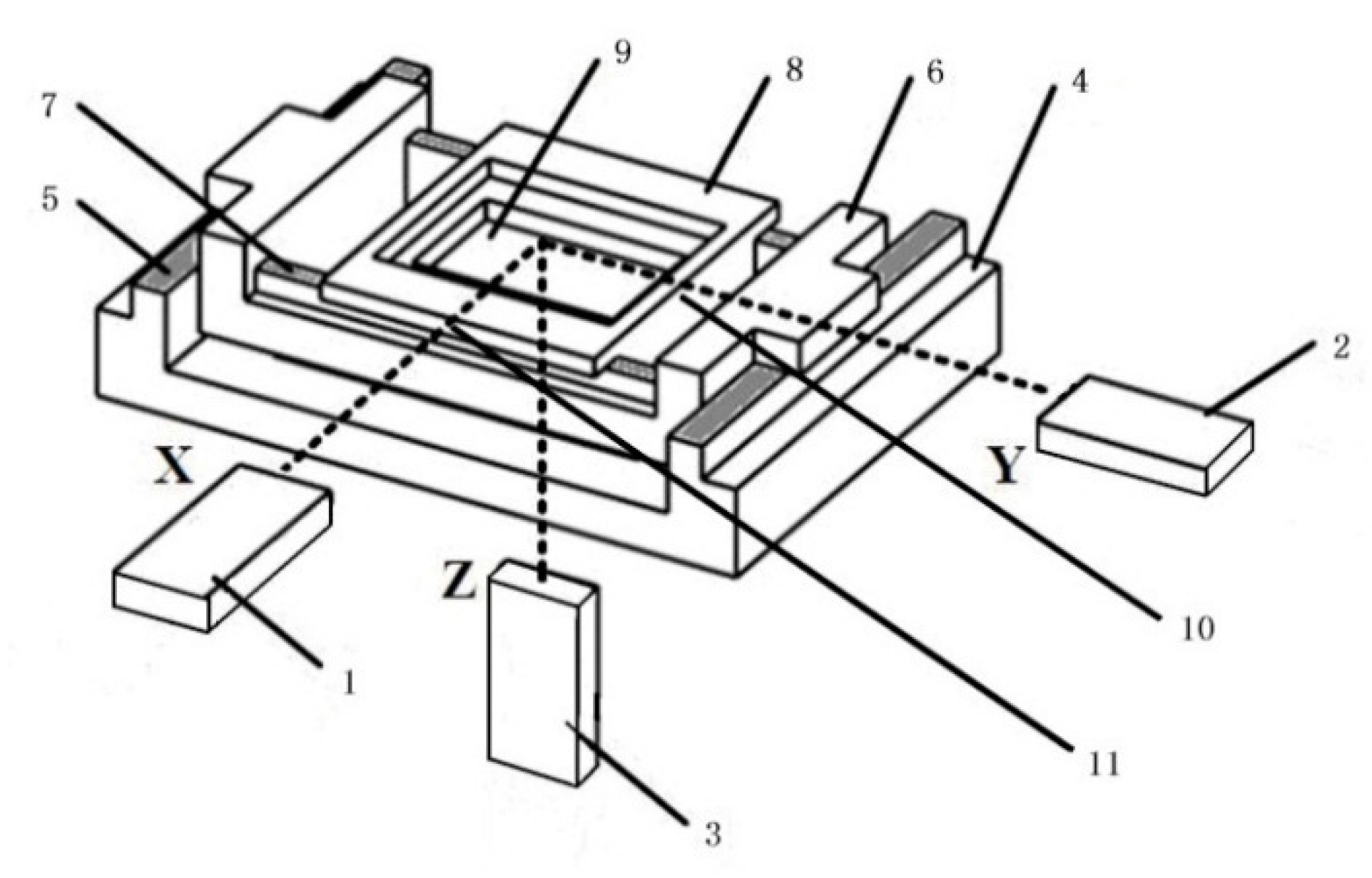
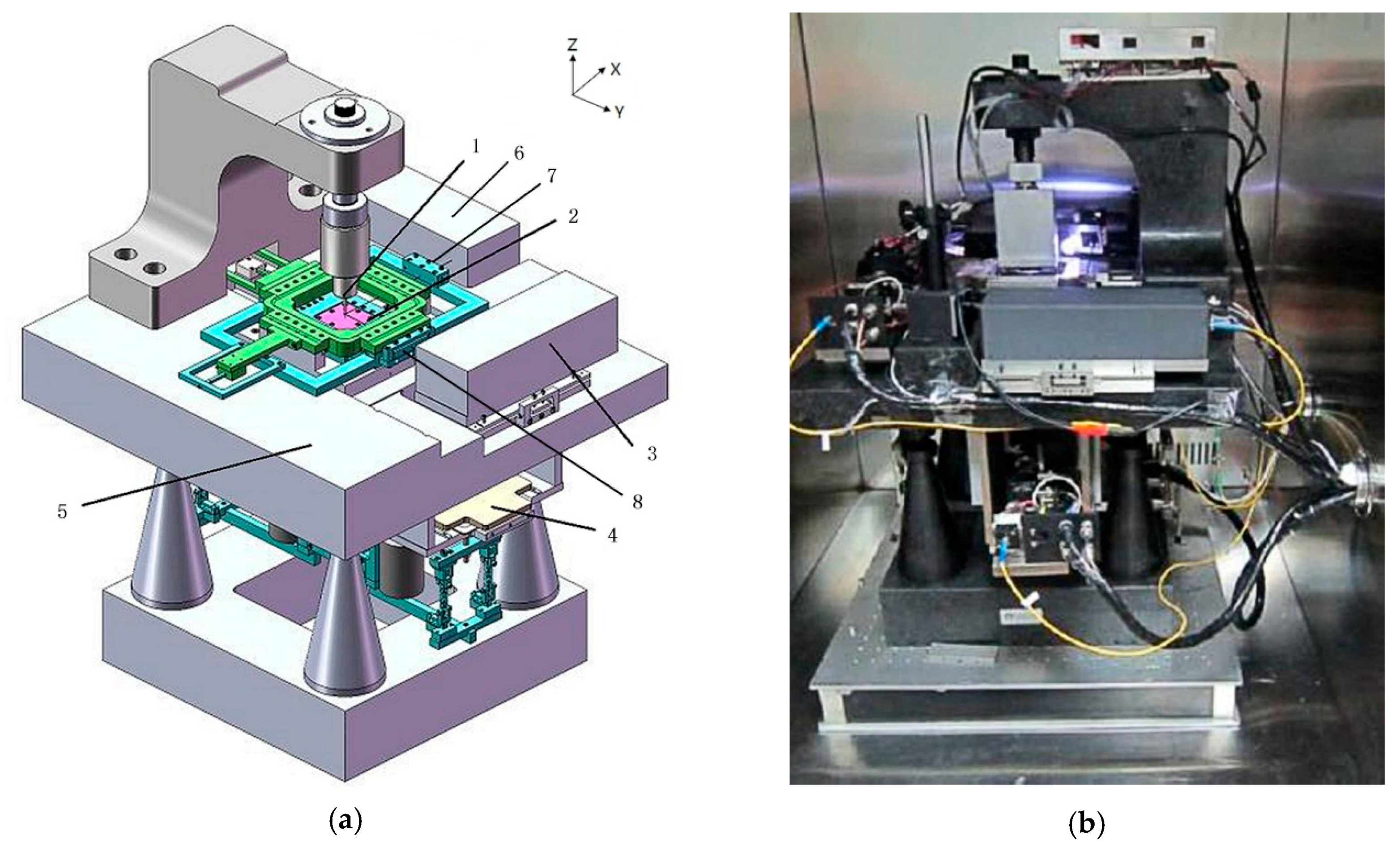
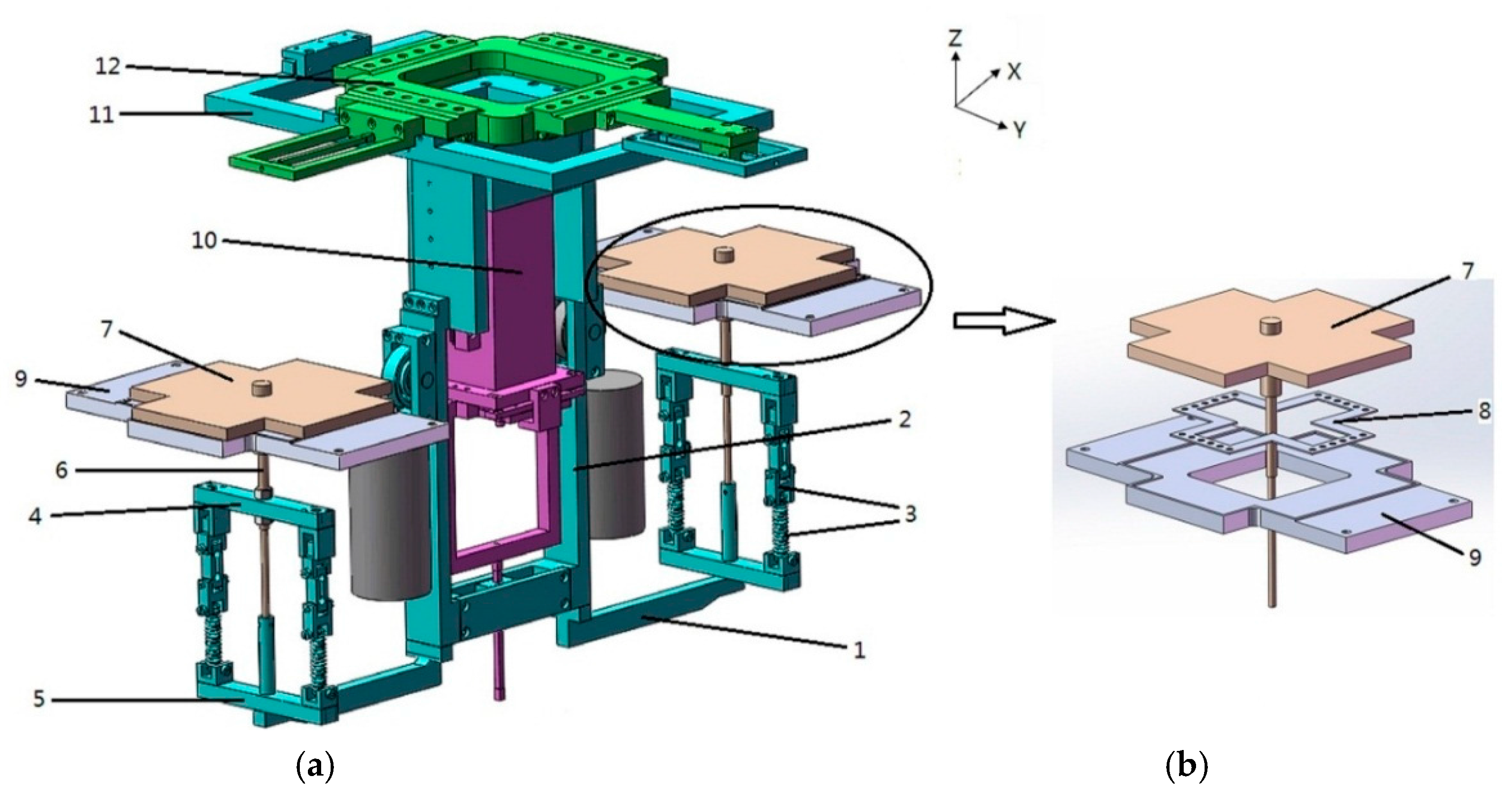
2.1. Basic Structure

The schematic structure of the developed micro CMM is shown in Figure 1a. The measuring probe (1) is located under a granite column which is fixed on the granite base (5). The tip-ball of the stylus probe is placed at the center of the XYZ three-dimensional (3D) stage (2) and kept still after assembly. The sample is mounted on a moving table of the 3D stage and can be moved in X, Y and Z directions together with the stage. Two deadweight balance systems (4) are connected to the 3D stage and the granite base. They can transfer the deadweight of the 3D stage to the granite base. The position of each axis is measured by the corresponding laser interferometer (3). The reflection mirrors (7) and (8) of X- and Y-interferometers are fixed on two of the lateral sides of Y-stage. The reflection mirror of Z-interferometer is mounted on the bottom of Z-stage. The Z-interferometer and its reflection mirror are concealed and invisible in Figure 1. Figure 1b shows the photography of the main mechanical assembly of the developed micro CMM which is located in a thermostatic chamber isolated on an anti-vibration base.
Abbe principle is the basis for all linear instrument designs. It is easy to obey the Abbe principle in a one-dimensional measurement but difficult to satisfy in all directions for a multi-dimensional measurement system. In conventional CMMs, measuring scales are always mounted on one side of each stage so that their metrological systems do not follow the Abbe principle. Abbe errors in conventional CMMs have to be reduced by well manufacture, fine adjustment in fabrication and error correction after assembly. However, limited by these efforts, the metrological systems of the conventional CMMs have difficulty achieving measurement accuracy better than 100 nm due to Abbe errors.
In order to follow the Abbe principle, a special structural design different from conventional CMMs is identified, as shown in Figure 2. The reflection mirrors (10) and (11) of X- and Y-interferometers are fixed on two of the vertical sides of the Y-stage (8). The reflection mirror of Z-interferometer (9) is mounted under the bottom of Z-stage (9). It can be seen that the length reference lines (represented by laser beams) of three axes (X, Y, Z) are perpendicular to each other and intersect at one fixed point, which is corresponding to the measuring point of the CMM. In addition, the X-guideway (5) and Y-guideway (7) are placed at the same height level and coincident with the reference plane (common plane) which is constructed by X-Y reference lines. All the guideways use roller bearing. The X-stage (6) and Y-stage (8) constitute a co-planar structure. These key components will be described in detail as follows.

2.2. Special Structure of the 3D Stage

Multi-dimensional stages can be constructed easily by stacking up several one-dimensional stages in series. However, the motion error is serious in this type of structure because the pitch angular errors of the bottom stage are magnified by the vertical offset between the guiding plane and the measurement point [11]. In order to reduce the motion error and the crosstalk between X- and Y-stages, a special mechanical structure is introduced as shown in Figure 2, where the X and Y bearings are almost co-planar and at the same height as the interferometer beam.
In Figure 2, the Z-stage (9) is embedded in the Y-stage and can be moved by roller bearing in the vertical direction. The Y-stage, together with the Z-stage, can be moved in the Y direction along the Y-guideway. The X-stage, together with the Y- and the Z-stages, can be moved in the X direction along X-guideway. The X-guideway between the granite base (4) and the X-stage shares the same horizontal plane with the Y-guideway, forming a co-planar stage. The Z-stage can be moved up and down through the X-Y co-planar stage. In this arrangement of the 3D stage, Abbe errors as well as crosstalk moving errors among X-, Y- and Z-stages are minimized. The strokes of the 3D stage in X, Y and Z directions are all 50 mm. The main body of the 3D stage is made of invar steel so as to reduce the thermal deformation of mechanical parts. The X-, Y-, Z-stages are driven respectively by three custom-made linear piezo-motors based on the type of N-310 provided by Physik Instrumente (Karlsruhe, Germany). The displacement resolution is about 1 nm.

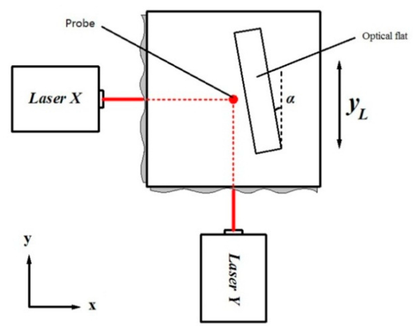
2.3. The Metrological System and Its Layout

The metrological system consists of three laser heterodyne interferometers, developed by Zhang et al. [12,13] to measure the movements of the 3D stage in X, Y and Z directions, respectively. The reflectors of the interferometers are plane mirrors. The location of reflection mirrors are shown in Figure 1 and Figure 2. The laser frequency of the three interferometers is stabilized at the level of about 10−7. The resolution of the interferometer is 1 nm.
The layout of the metrological system is well arranged so that all interferometers are fixed on the granite base and independent from the 3D stage, as shown in Figure 1. The three measuring lines, represented by the three laser beams of the three corresponding interferometers, are parallel to the movement directions of the 3D stage and orthogonal to each other. They intersect at the measuring point, which is corresponding to the center of the probe’s tip-ball, as shown by the dotted lines in Figure 2. The measuring lines of X- and Y-interferometers, X-guideway and Y-guideway are in the same plane. Therefore, such a metrological system obeys the Abbe principle and the crosstalk is minimized.

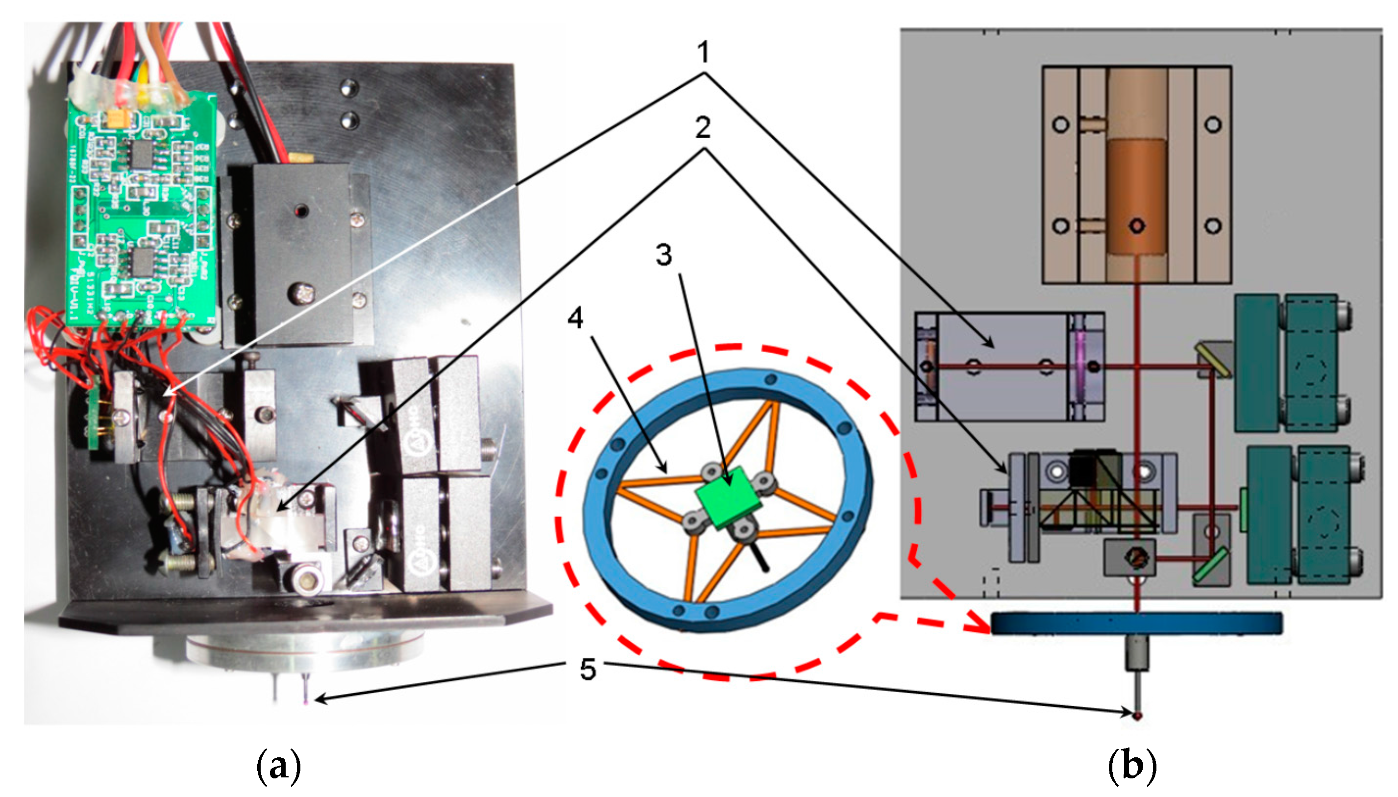
2.4. The 3D Measuring Probe

A contact probe [14] is adopted in this micro CMM. The physical and schematic structures of the probe are shown in Figure 3. The probe system mainly consists of an autocollimator (1), a mini Michelson interferometer (2), a suspension mechanism constructed by high sensitive elastic leaf springs (4), a reflection mirror (3) and a stylus with ruby ball (5). When the sample on the 3D stage contacts the probe ball and causes a deflection of the stylus, the reflection mirror will generate two angular displacements and a vertical displacement. Displacements of the mirror are functions of the linear deflection of the probe ball in X, Y and Z directions. The two angular displacements of the mirror are detected by the home-made autocollimator, and the vertical displacement is detected by the home-made Michelson interferometer. Then, the displacement of the probe ball in X, Y and Z directions can be calculated according to the output signals of the autocollimator and the interferometer. The measurement range of probe is up to 20 μm and the resolution is 1 nm in all X, Y and Z directions. The repeatability of the probe is better than 30 nm (2σ). By careful design and fabrication, the stiffness of the probe in three directions is nearly uniform. The maximum touch force is less than 12 mN when the probe ball is deviated from the original position by 20 μm. In other words, the stiffness is about 0.6 mN/μm.

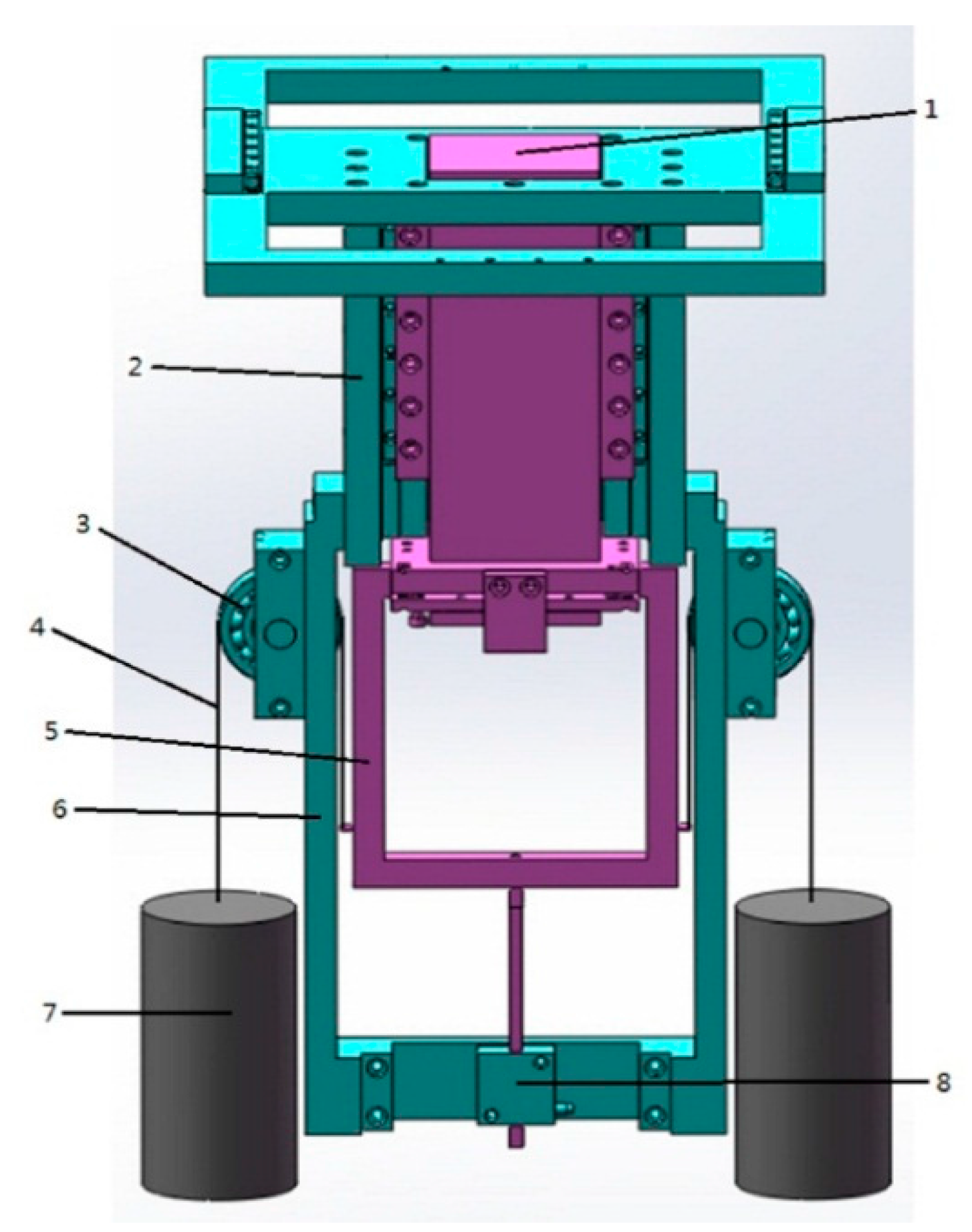
2.5. Deadweight Balance Structure

The Z-stage is moved together with X- and Y-stages. The deadweight of the moving table will cause structure deflection in the XY-plane and uneven driving forces in the Z-axis due to gravity effect. In order to reduce this mechanical deformation and inertial force, two sets of counterweight mechanisms are proposed in the developed micro CMM. One is used to balance the deadweight of the Z-stage, which is called the Z-stage deadweight balance system. The other is to balance of the deadweight of X-, Y- and Z-stages during lateral movement, which is called the lateral deadweight balance system. Details are given as follows.

2.5.1. Z-Stage Deadweight Balance System

The Z-stage can move in the Z direction alone and in X and Y directions together with X-Stage and Y-stage, respectively. Its motion is driven by a commercial linear piezo-motor provided by Physik Instrumente. The deadweight of the Z-stage will induce more actuation force if it is moved up. In order to overcome this problem, a force balance system for Z-stage deadweight is particularly designed. Figure 4 shows the schematic structure. The Z-stage (1) and its supporting frame (5) are fixed together and driven by the linear piezo-motor (8). The Y-stage (2), pulley (3) and outer frame (6) are fixed together. Two counterweights (7) and the supporting frame (5) are connected by two thin steel strips (4). The total weight of two counterweights is equal to the net weight of the Z-stage and its accessories. In this mechanical structure, the Z-stage can be driven by the actuator with a low and equal driving force in both up and down motions.

2.5.2. Lateral Deadweight Balance System

In Figure 4, although the deadweight of the Z-stage is balanced by two counterweights, the total deadweight of the Z-stage with its accessories and its mechanical balance system is transferred to the Y-stage, then to the X-stage during Y and X motions. When the Y- or X-stage moves laterally, the total center of the gravity of the moving body moves and will cause structural deformation to the degree of micrometers, which is unacceptable in the developed machine. In order to balance the deadweight of the X- and Y-stages and the balance system of the Z-stage, we developed a lateral deadweight balance mechanism, as schematically shown in Figure 5. Through this mechanism, their deadweight is transferred to the granite base, which has a high stiffness.
In Figure 5, the X-stage (12) is located on the granite base (not shown in this figure for clarity) and can move only along the X direction. The Y-stage (11) together with the balanced Z-stage can move not only in the Y direction along the Y-guideway but also in the X direction together with the X-stage.
Two horizontal arms (1) are fixed to the bottom of the outer frame (2) symmetrically and move together with the Y-stage. The lower arm (5), upper arm (4), springs and tension sensors (3), guide rod (6) and upper plate (7) are connected rigidly in the lateral direction. Thus, the movement of X- and Y-stages in the lateral direction is transferred to the upper plate (7). The upper plate, guide rod and upper arm are connected rigidly, and are also connected with the lower arm through two springs and tension sensors in each side. The tension forces of four springs are measured by four tension sensors respectively. During fabrication of the stages, the tension forces of the four springs are adjusted to be equal. In Figure 5b, the two-dimensional moving stage is composed of the upper plate, rolling bearing (8) and lower plate (9). The lower plate in each side is fixed rigidly to the granite base (not shown in this figure for clarity). The upper plates can move on the lower plates with a very low friction through the linear rolling bearing. Therefore, the total deadweight of all the moving parts is transferred to the granite base, and the stages can move in lateral direction smoothly.

3. Analysis and Correction of Main Errors

Although the developed micro CMM obeys Abbe principle in X, Y and Z directions, and some unique key technologies mentioned above are adopted to reduce systematic errors, some other errors are still obvious compared to the required measurement accuracy. These errors are frequency stability of the laser interferometer, flatness errors of long reflection mirrors for laser interferometers and non-orthogonal errors between interferometers. These errors are analyzed, separated and corrected in the following.

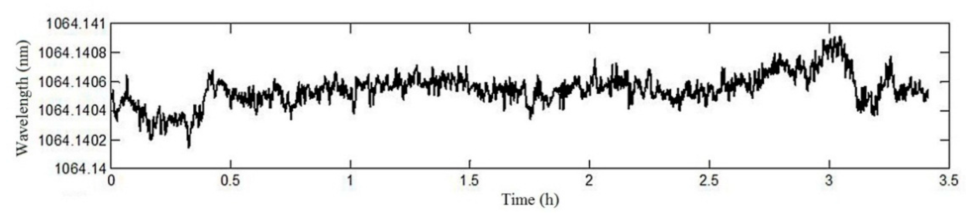
3.1. Stability of Frequency Stabilized Nd:YAG Laser Feedback Interferometer

In this micro CMM, movements in X, Y and Z directions are measured by three Nd:YAG laser feedback interferometers developed by Zhang et al. [12,13]. Frequencies of all three lasers are stabilized. The frequency stability error of each laser is less than 10−7. Figure 6 shows the fluctuation of one interferometer’ wavelength during 3–4 h. It can be estimated that the maximum measuring error caused by the frequency stability error is about 26 nm (2σ).

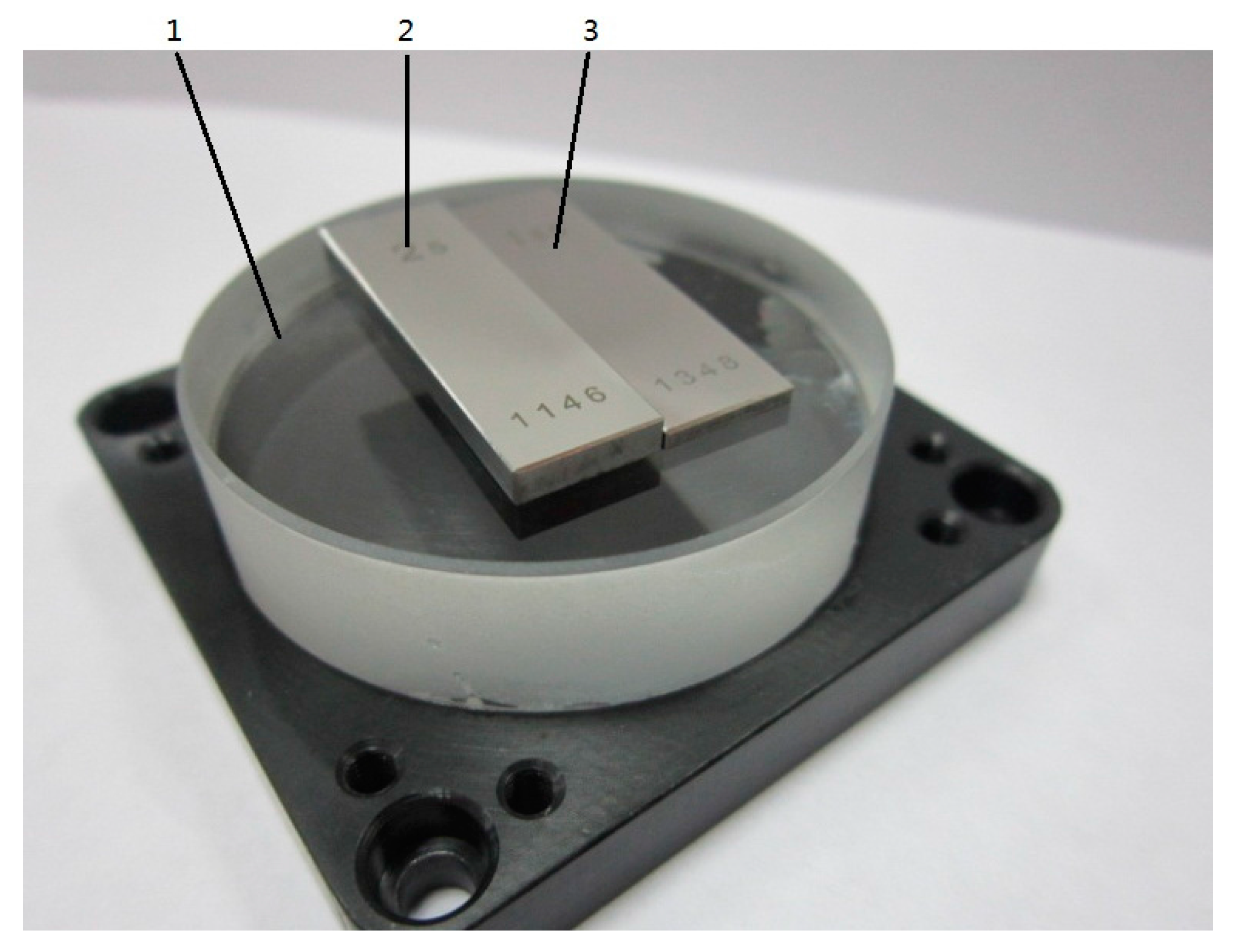
3.2. Error Calibration and Correction of Interferometers’ Reflection Mirrors

The reflection mirrors of the three interferometers are fixed on the moving table. However, the reflection surfaces of mirrors themselves are not ideal flat and the surface deformation of each mirror is inevitable after the mirrors are fixed on the moving table. The straightness in X- and Y-mirrors and the flatness in Z-mirror will contribute to the final measuring result directly. Therefore, the errors of reflection mirrors should be separated and corrected. Figure 7 shows the schematic diagram of the straightness error separation of reflection mirror of X-interferometer. After the error calibration and correction, the measurement straightness of the optical flat is about 57 nm.
In Figure 7, an optical flat with the accuracy of grade one is placed on the stage. The maximum flatness error of the optical flat’s measuring surface is less than 30 nm. Here, the measuring surface of the optical flat is used as the reference and is adjusted parallel to the long reflection mirror surface to the best we can. In other words, the angle of α should be as small as possible. Then, the measuring surface of the optical flat is measured by the micro CMM. Using the obtained data, the straightness error of the X-interferometer’s reflection mirror can be calibrated and its systematic error can be corrected. By this approach, the straightness of the Y-mirror and flatness of the Z-mirror are calibrated and corrected. After the error calibration and correction, all residual errors are less than 50 nm (2σ).

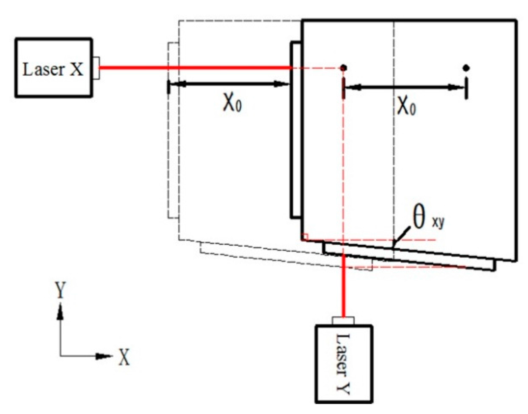
3.3. Separation and Correction of Non-Orthogonal Errors

According to the layout of our developed micro CMM, the surfaces of three reflection mirrors should be exactly orthogonal to each other. If it is not, non-orthogonal errors occur and increase the final measured error directly. Firstly, the guideways of the X-, Y- and Z-stages are adjusted to be orthogonal exactly by a calibrated square gauge. Then the interferometers are adjusted to keep the laser beam parallel with the X-, Y- and Z-guideways respectively. After that, the reflection mirrors are adjusted to be orthogonal according to the guideways. For example, Figure 8 shows the schematic diagram of the orthogonal error between reflection mirrors of X- and Y-interferometers. Provided that θxy is the non-orthogonal angular error between X- and Y-mirrors and the stage is moved by a displacement of x0 in the X direction, the Y-interferometer will read an output error of Δyy = x0·tanθxy). This error will add to the Y coordinate of the measured point. In order to separate the non-orthogonal errors among three mirrors, the stage is moved in one direction only. Then, the outputs of other two interferometers are the combination of the flatness errors and non-orthogonal errors. Since systematic flatness errors of the mirrors are known because they have been corrected in the above section, then the non-orthogonal errors are obtained from the interferometers’ outputs after the systematic flatness errors are subtracted. All the other non-orthogonal errors can be separated and corrected according to the same method. After the calibration and correction, all of the non-orthogonal errors are less than about 40 nm (2σ).
Besides the above errors, there are other remained errors. One is the thermal expansion error. The temperature control accuracy in the measuring area is ±0.5 °C. If the material of the ample (gauge block) is 12 × 10−6 and its length is 50 mm, then the thermal expansion error is about 30 nm (2σ).
The second is the residual Abbe error. The diameter of the probe ball used here is 1 mm. In Section 2.3, the center of the probe’s tip-ball can not be adjusted at the right center of the laser beams of the three interferometers. This offset is within ±0.5 mm. These two offsets are Abbe offset. The motion angular error of X-, Y-stages is within ±6”. Then, the Abbe error caused by this two offsets is about 30 nm (2σ). In Z direction, the maximum Abbe offset is the maximum measuring length 6 mm of the probe stylus. The motion angular error of X-, Y-stages is within ±2.1”. Then, the Abbe error in Z direction is about 61 nm (2σ).

4. Performance Tests

In order to verify the measuring accuracy of the developed micro CMM, some high precision microparts, formed by gauge blocks with high grade, are adopted as samples to be measured. During the tests, the temperature of the thermostatic chamber is controlled at 20.00 °C ± 0.1 °C. Near the probe, the temperature is at 20.00 °C ± 0.05 °C. All of the gauge blocks used in this paper were calibrated with the accuracy of class 1 by the National Institute of Metrology, Beijing, China. The calibration uncertainty (2.96σ) of the gauge blocks is (0.020 + 0.1×10⁻⁶·ln) μm. Here, ln is the nominal length of the gauge block. Performance tests are introduced in the following.

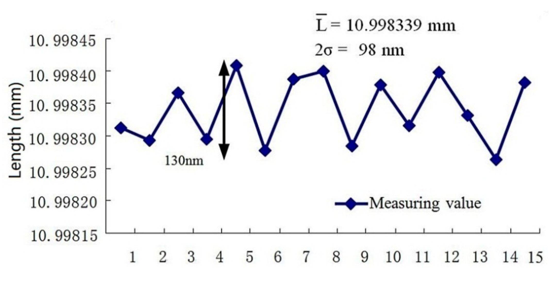
4.1. Step Height Measurement in Z Direction

The step height in the Z direction was formed by the difference of two class 1 gauge blocks having calibrated lengths of 2.000022 mm and 5.000024 mm respectively, as shown in Figure 9. They were located together on the surface of the optical flat (the flatness error is less than 30 nm), which is fixed on the 3D stage. Six points on one surface of the gauge block (3) were measured by the developed micro CMM. A reference plane of it was then calculated by the least squares method. For the gauge block (2), the coordinate of the center point of the upper surface was measured. Then, the step height of the two gauge blocks is the distance between the center point and the reference plane. According to this method, the step height of the two gauge blocks was measured 15 times. The average value of the 15 repeated measurements was 3.000006 nm. The standard deviation (σ) was 21 nm. The average value 3.000006 mm of 15 repeated measurements is very close to the difference 3.000002 mm between the two calibrated values. During the measuring process, the triggering direction of the probe was in the vertical direction, so there was no need to compensate the probe radius.
The step height measurement errors are mainly from the interferometer (26 nm, k = 2), the residual Abbe error (30 nm, k = 2), the repeatability error of the probe (30nm, k = 2), the error from reflection mirror (50 nm, k = 2). Neglecting other errors sources, the measurement uncertainty is about 71 nm (k = −2).

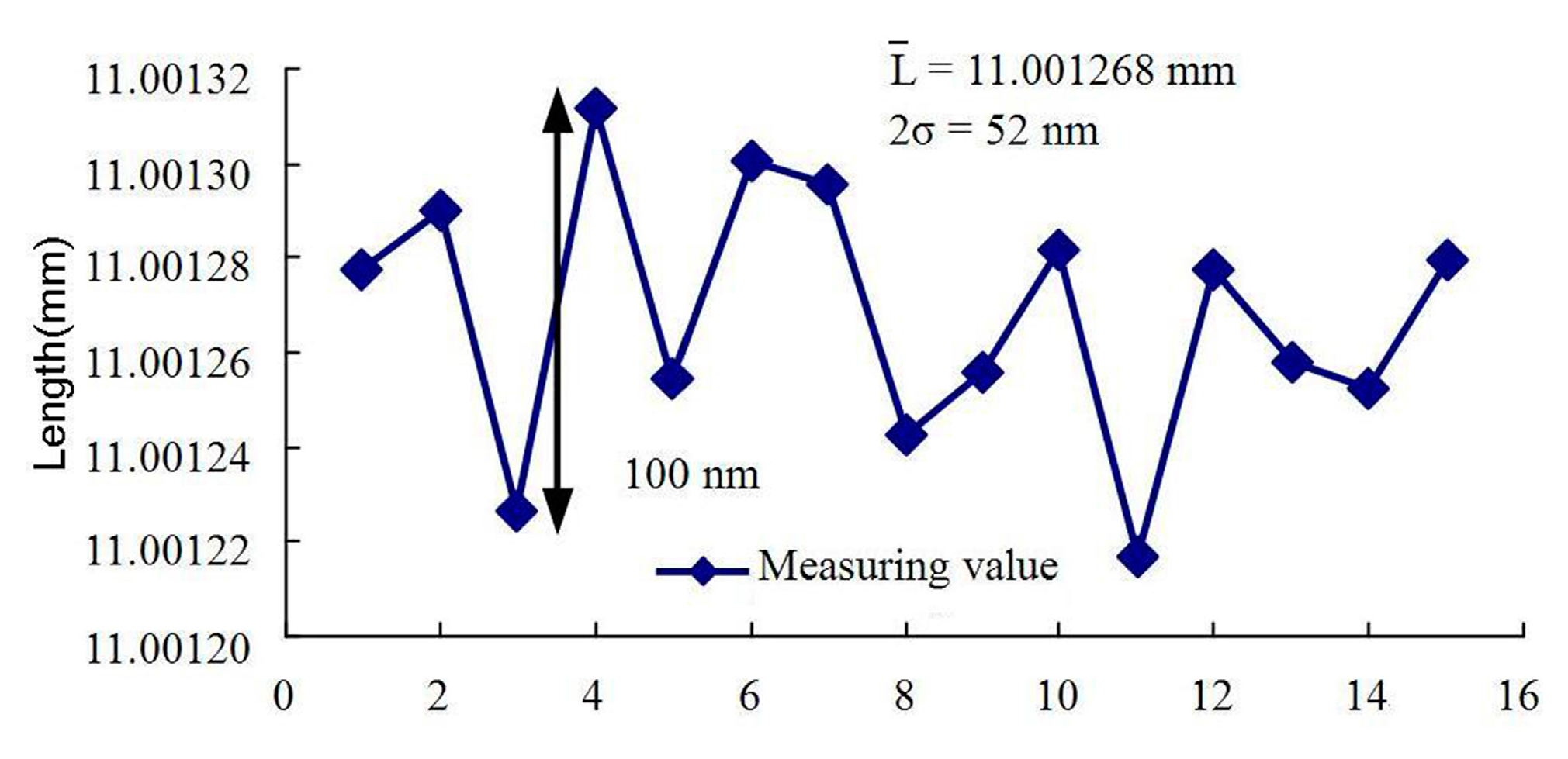
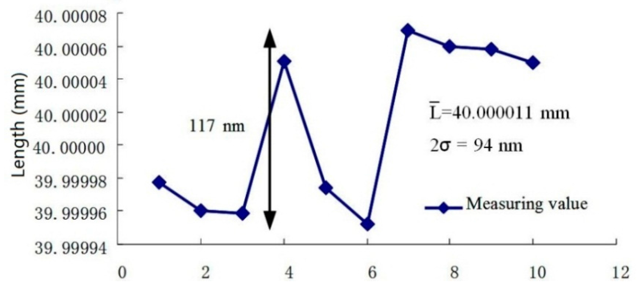
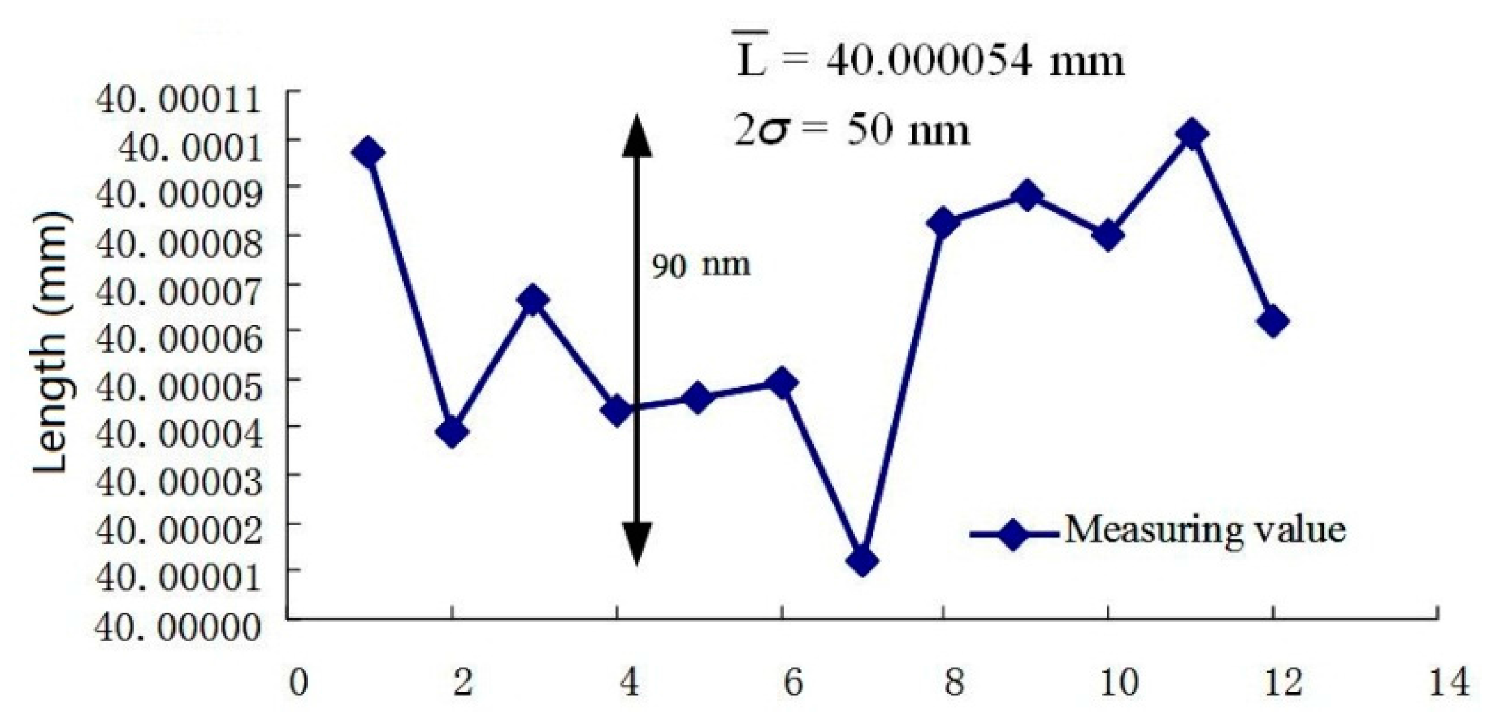
4.2. Length Measurement in Lateral Direction

Because of the diameter error of the ball itself, the roundness deviation of the ball and the deflection of the ball stylus at triggering point, the equivalent diameter of the probe ball in the measuring direction should be known in advance. Here, the equivalent diameter of the probe in the measuring direction is calibrated firstly in the measurement direction by a reference gauge block with high accuracy. Then, the calibrated value is subtracted from the obtained data of the sample.
In the estimation of the equivalent diameter of the probe ball, six points on one measuring face of the reference gauge block (its calibrated value is 10.000045 mm) were measured by the developed micro CMM firstly. Using the coordinates of the six points, a reference plane was calculated by the least squares method. Then, one point on the opposite measuring face of the reference gauge block was measured. The distance between this point and the reference plane is the sum of the dimension of the gauge block and the equivalent diameter of the probe ball. Figure 10 shows the results of a 15 times repeated measurement (The horizontal coordinate is the order of measurement). Neglecting the dimensional error of the reference gauge block, the equivalent diameter of the probe ball in the X direction was calculated as rx = 11.001268 mm − 10.000045 mm = 1.001223 mm. The standard deviation (σ) of the repeatability is about 26 nm.
After the equivalent diameter of the probe in the measurement direction had been calibrated, the reference gauge block was replaced by the sample gauge block in the same location and same direction. After the equivalent diameter of the probe ball was subtracted from the measured value, the measured dimension of the sample gauge block could be obtained. Figure 11 shows 10 times measurement results of a sample gauge block with calibrated length of 40.000039 mm. The measured dimension is about 40.000011 mm on average and the standard deviation is about 47 nm.
Another test was done in the Y direction with the same setup as in the X direction. Figure 12 shows the probe diameter calibration results. The 10 times average equivalent diameter of the probe in Y direction is 0.998294 mm. The standard deviation (σ) of the repeatability is about 47 nm. Figure 13 shows 12 times measurement results of the same sample gauge block. The measured dimension is about 40.000054 mm on average and the standard deviation is about 45 nm.
In the lateral length measurement, the measurement errors are mainly from the interferometer (26 nm, k = 2), the thermal expansion error (24 nm, k = 2), the Abbe error (30 nm, k = 2) in lateral direction, the Abbe error in Z direction (61 nm, k = 2), the repeatability error of the probe (30 nm, k = 2), the error from reflection mirror (50 nm, k = 2), the non-orthogonal error (40 nm, k = 2). Neglecting other error sources, the measurement uncertainty is about 106 nm (k = 2).
Although the equivalent diameters of the probe ball in different directions shown in Figure 10 and Figure 12 are different, but the measured dimensions of the sample gauge block, shown in Figure 11 and Figure 13, have no obvious difference (about 43 nm).

4.3. Flatness Error Measurement

For verifying the flatness error of the developed micro CMM, a standard gauge block with the measuring face flatness of 30 nm was used to be measured. The gauge block was set on the Z stage directly. The probing direction is vertical. Six points are sampled on the surface of the gauge block with the measurement zone of 13 mm × 4 mm. The calculation of the flatness is based on the least squares method. The obtained coordinates of the six points are given in Table 1. The result of the flatness error was 66 nm. Other measuring surfaces of the gauge blocks were measured. Their flatness is in the same level.
In fact, we measured the flatness of an optical flat of Grade 0 with nominal diameter of 45 mm, which is the highest grade. We measured two areas of the measuring surface of the optical flat. One is 12 mm × 12 mm and the other is 28 mm × 28 mm. The obtained flatness errors were 56 nm and 62 nm, respectively.

5. Conclusions

This paper introduces a developed micro CMM with some new design ideas, especially with the metrological layout of being Abbe error free. In this machine, a structure of a co-planar stage is adopted so as to reduce the Abbe error and crosstalk among X-, Y- and Z-stages. A previously developed 3D measuring probe with the measuring range of 20 μm was adopted for use. The probe ball, the metrological system and 3D stage are carefully arranged so that the Abbe error is free. Experimental results show that the measurement uncertainty in X, Y and Z directions with 40 mm is about 100 nm (2σ) and the flatness error of measuring surface of the sample gauge block is about 66 nm.
This micro-CMM can only measure simple dimensions. For more complicated dimensions, further research is needed.

Acknowledgments

The authors acknowledge gratefully the support of the National High-Tech R & D Program (863 Program) (Project code: 2008AA042409) and the National Natural Science Foundation of China (Project code: 51475131 and 51175141).

Author Contributions

Qiangxian Huang established the layout of the micro system, and took part in the mechanical design, control system and experiments. Kui Wu contributed mainly to the control system and experiments. Chenchen Wang established the mechanical system and software, and took part in the experiments. Ruijun Li contributed to the probe system and took part in the experiments. Kuang-Chao Fan contributed to the probe system and co-planar stage. Yetai Fei took part in the establishment of the metrological system and mechanical system.

Conflicts of Interest

The authors declare no conflict of interest.

References

  1. Claverley, J.D.; Leach, R.K. A review of the existing performance verification infrastructure for micro-CMMs. Prec. Eng. 2015, 39, 1–15. [Google Scholar] [CrossRef]
  2. Kramar, J.A. Nanometre resolution metrology with the Molecular Measuring Machine. Meas. Sci. Tech. 2005, 16, 2121–2128. [Google Scholar] [CrossRef]
  3. Yang, P.; Takamura, T.; Takahashi, S.; Takamasu, K.; Sato, O.; Osawa, S.; Takatsuji, T. Development of high-precision micro-coordinate measuring machine: Multi-probe measurement system for measuring yaw and straightness motion error of XY linear stage. Prec. Eng. 2011, 35, 424–430. [Google Scholar] [CrossRef]
  4. Brand, U.; Kleine-Besten, T.; Schwenke, H. Development of a special CMM for dimensional metrology on microsystem components. In Proceedings of the Sixth International Symposium on Precision Mechanical Measurements, GuiYang, China, 8 August 2013; pp. 542–546.
  5. Lewis, A.; Oldfield, S.; Peggs, G.N. The NPL Small CMM-3-D measurement of small features. 5th LAMDAMAP. 2001, 34, 197–207. [Google Scholar]
  6. Manske, E.; Jäger, G.; Hausotte, T.; Füβl, R. Recent developments and challenges of nanopositioning and nanomeasuring technology. Meas. Sci. Tech. 2012, 23, 74001–74010. [Google Scholar] [CrossRef]
  7. Balzer, F.G.; Hausotte, T.; Dorozhovets, N.; Manske, E.; Jäger, G. Tactile 3D microprobe system with exchangeable styli. Meas. Sci. Tech. 2011, 22. [Google Scholar] [CrossRef]
  8. Schmidt, I.; Hausotte, T.; Gerhardt, U.; Manske, E.; Jäger, G. Investigations and calculations into decreasing the uncertainty of a nanopositioning and nanomeasuring machine (NPM-Machine). Meas. Sci. Tech. 2007, 18, 482–486. [Google Scholar] [CrossRef]
  9. Kornel, F.E.; David, B.; Martin, L.C.; Thom, J.H.; Thomas, R.K.; Marc, M.; Kamlakar, R.; Richard, D. Micromanufacturing; Springer: Dordrecht, The Netherlands, 2007; pp. 89–109. [Google Scholar]
  10. Spaan, H.A.M.; Widdershoven, I. Isara 400 Ultra-precision CMM. In Proceedings of the Optical Fabrication, Testing, and Metrology IV, Marseille, France, September 2011.
  11. Fan, K.C.; Fei, Y.T.; Yu, X.F.; Chen, Y.J.; Wang, W.L.; Chen, F.; Liu, Y.S. Development of a low-cost micro-CMM for 3D micro/nano measurements. Meas. Sci. Tech. 2006, 17, 524–532. [Google Scholar] [CrossRef]
  12. Tan, Y.D.; Zhang, S.L. Self-mixing interference effects of microchip Nd:YAG laser with a wave plate in the external cavity. Appl. Opt. 2007, 46, 6064–6048. [Google Scholar] [CrossRef] [PubMed]
  13. Tan, Y.D.; Zhang, S.L.; Zhang, S.; Zhang, Y.Q.; Liu, N. Response of microchip solid-state laser to external frequency-shifted feedback and its applications. Sci. Rep. 2013, 3. [Google Scholar] [CrossRef]
  14. Li, R.J.; Fan, K.C.; Miao, J.W.; Huang, Q.X.; Tao, S.; Gong, E.M. An analogue contact probe using a compact 3D optical sensor for micro/nano coordinate measuring machines. Meas. Sci. Tech. 2014, 25, 1–9. [Google Scholar] [CrossRef]
Figure 1. (a) schematic structure of the micro CMM (Coordinating Measuring Machines). (b) the photography of the mechanical assembly of the developed micro CMM. 1: Measuring probe, 2: XYZ stage, 3: Y-interferometer, 4: Deadweight balance, 5: Granite base, 6: X-interferometer, 7: Reflection mirror of X-interferometer, 8: Reflection mirror of Y-interferometer.
Applsci 06 00097 g001
Figure 2. Schematic structure of 3D stage and schematic layout of metrological system. 1: X-interferometer (length reference), 2: Y-interferometer (length reference), 3: Z-interferometer (length reference), 4: Granite base, 5: X-guideway between X-stage and granite base, 6: X-stage, 7: Y-guideway between X- and Y-stages, 8: Y-stage, 9: Z-stage, 10: Reflection mirror of Y-interferometer, 11: Reflection mirror of X-interferometer.
Applsci 06 00097 g002
Figure 3. Physical and schematic structures of the 3D measuring probe. (a) physical picture of the probe; (b) schematic structure. 1: Autocollimator, 2: Michelson interferometer, 3: Mirror, 4: High sensitive elastic leaf spring, 5: Stylus with ruby ball.
Applsci 06 00097 g003
Figure 4. Schematic structure of Z-stage deadweight balance system. 1: Z-stage, 2: Y-stage 3: Pulley, 4: Steel strip, 5: Support frame, 6: Outer frame (It is fixed with Y stage), 7: Counterweight, 8: Linear piezo-motor.
Applsci 06 00097 g004
Figure 5. Schematic structure of the lateral deadweight balance system. 1: Horizontal arm, 2: Outer frame, 3: Spring and tension sensor, 4: Upper arm, 5: Lower arm, 6: Guide rod, 7: Upper plate, 8: Rolling bearing group, 9: Lower plate, 10: Z-stage, 11: Y-stage, 12: X-stage.
Applsci 06 00097 g005
Figure 6. Calibration of the wavelength of one interferometer.
Applsci 06 00097 g006
Figure 7. Schematic diagram of the surface flatness calibration of X-interferometer’s reflection mirror.
Applsci 06 00097 g007
Figure 8. Schematic diagram of X-Y non-orthogonal error.
Applsci 06 00097 g008
Figure 9. Step height measurement schematic diagram between two gauge blocks. 1: Optical flat; 2: Calibrated gauge block 1; 3: Calibrated gauge 2.
Applsci 06 00097 g009
Figure 10. The repeated measuring results of sample gauge block.
Applsci 06 00097 g010
Figure 11. The measuring length of a gauge block with the nominal length of 40 mm.
Applsci 06 00097 g011
Figure 12. Calibration of the diameter of the probe ball by reference.
Applsci 06 00097 g012
Figure 13. The measuring results of a sample gauge block.
Applsci 06 00097 g013
Table 1. Obtained coordinates of 6 points on the measuring surface of a gauge block and flatness.
PointCoordinates (xi, yi, zi) (mm)PointCoordinates (xi, yi, zi) (mm)
1(18.004414, 34.999884, 34.741144)2(18.003694, 28.000295, 34.741274)
3(18.002475, 22.000374, 34.741458)4(22.004273, 21.995507, 34.731724)
5(22.005775, 27.999635, 34.731491)6(22.006136, 34.999752, 34.731304)
Flatness66 nm

