Review

A Review of Double-Walled and Triple-Walled Carbon Nanotube Synthesis and Applications

1
Faculty of Engineering, Shinshu University, 4-17-1 Wakasato, Nagano, Nagano 380-8553, Japan
2
Department of Physics and Center for 2-Dimensional and Layered Materials, The Pennsylvania State University, University Park, PA 16802, USA
3
School of Polymer Science and Engineering and Department of Polymer Engineering, Graduate School, Chonnam National University, 77 Yongbong-ro, Buk-gu, Gwangju, 61186, Korea
4
Attocube Systems AG, Königinstraße 11a, 80539 Munich, Germany
5
Department of Electrical Engineering and Computer Science, Department of Physics, Massachusetts Institute of Technology, Cambridge, MA 02139-4307, USA
6
Department of Physics and Astronomy, University of Alabama, Tuscaloosa, AL 35401, USA
7
Center for Materials for Information Technology (MINT Center), University of Alabama, Tuscaloosa, AL 35401, USA
*
Authors to whom correspondence should be addressed.
Appl. Sci. 2016, 6(4), 109; https://doi.org/10.3390/app6040109
Submission received: 31 December 2015 / Revised: 7 March 2016 / Accepted: 9 March 2016 / Published: 16 April 2016

Abstract

:
Double- and triple-walled carbon nanotubes (DWNTs and TWNTs) consist of coaxially-nested two and three single-walled carbon nanotubes (SWNTs). They act as the geometrical bridge between SWNTs and multi-walled carbon nanotubes (MWNTs), providing an ideal model for studying the coupling interactions between different shells in MWNTs. Within this context, this article comprehensively reviews various synthetic routes of DWNTs’ and TWNTs’ production, such as arc discharge, catalytic chemical vapor deposition and thermal annealing of pea pods (i.e., SWNTs encapsulating fullerenes). Their structural features, as well as promising applications and future perspectives are also discussed.

1. Introduction and Motivation

Before starting with the Introduction and definitions, it is important to keep in mind that this manuscript is intended to briefly review and discuss the recent progress on the controlled growth of double-walled carbon nanotubes (DWNTs) and triple-walled carbon nanotubes (TWNTs), which are the few-walled versions of the single-walled carbon nanotubes (SWNTs). Namely, since they were first discovered [1], carbon nanotubes (CNTs) have undoubtedly been one of the most promising nano-materials to advance applications in mechanics, electronics, materials science, sensors, energy harvesting devices and much more [2,3,4].

1.1. Single-Walled Carbon Nanotubes

SWNTs can be simply understood from a fundamental nano-science standpoint on the basis of their parent material graphene, the material that led to their discovery, and which was awarded the Nobel Prize in 2010 [2,3,4,5,6]. As depicted in Figure 1a, departing from the origin O for graphene using the direct space basis vectors a 1 and a 2 , the chiral vector ( C h ) is generated by displacing the vector n times in the a 1 direction and m times in the a 2 direction, forming the ( n , m ) chiral vector ( 4 , 2 ). Next, a stripe whose width is equal to the C h size is “cut”, and by joining both ends of the chiral vector, one obtains a cylinder, which is nothing but the ( 4 , 2 ) carbon nanotube itself.
Each carbon nanotube has its very own ( n , m ) index, and through this ( n , m ) indexing, one may understand everything regarding the nanotube structure, as for example, its mechanical, electronic, vibrational and thermal structures [2,3,4]. The ( n , m ) index will, therefore, also define whether a carbon nanotube is metallic or semiconducting. Additionally, due to the carbon nanotube one-dimensional character, both the electronic and the vibrational structures of CNTs present Van Hove singularities (VHS), and these VHS enhance many phenomena involving electrons, phonons and their mutual interactions, which are often called many-body interactions [2,4,5,7,8,9,10]. These VHS have a high density of states, and they result from the quantum confinement observed in the circumferential direction of the nanotubes [2,4,5,7,8]. Lieber’s group was one of the first groups to measure the Van Hove singularities in CNTs using the scanning tunneling microscopy (STM) technique, as shown in Figure 1b [11].
From a theoretical point of view, there are no doubts about how unique nanotubes are, and if one could specifically synthesize a particular nanotube with a particular set of ( n , m ) values, one could certainly utilize these ( n , m ) numbers to build more efficient products, which are designed for a specific commercial application. As an example, semiconducting SWNTs have been used to fabricate field-effect transistors (FET) [12,13,14]. As demonstrated by Misewich et al. [12], optical emissions can be electrically induced from FETs (see Figure 2a,b). However, semiconducting SWNTs with different ( n , m ) indexes will present different bandgaps, and these different bandgaps make the FET light emissions happen at distinct wavelengths. Therefore, through a convenient selection of CNTs according to their ( n , m ) indexes, these FET devices could be tailored according to the desired emission wavelength. Moreover, such devices could be also used as light absorbers, photovoltaic cells and photo-current generators (see Figure 2c,d), for example [15,16,17,18,19,20]; all of them with performances directly relying on the specific ( n , m ) choices [12,13,14,15,16,17,18,19,20].
The bridge between theory and commercial applications, which is the focus of the study of researchers working with the synthesis of carbon nanotubes, was a major problem in the advancement and consolidation of CNTs as a “next generation” material [2]. In the past two decades, major progress has been made first towards synthesizing or isolating semiconducting nanotubes, metallic nanotubes and later ( n , m )-specific samples. These major advances give an additional boost to carbon nanotube science [21,22,23,24,25,26,27,28,29]. These advances brought along the capability of synthesizing better SWNT ( n , m )-specific samples and also provide more capability for synthesizing DWNT and TWNT samples containing either only DWNTs or only TWNTs [21,22,23,24,25,26,27,28,29].

1.2. Double- and Triple-Walled Carbon Nanotubes

DWNTs and TWNTs may be understood as two and three concentric SWNTs, respectively, which interact with each other through interlayer (IL) interactions, which are mediated by weak van der Waals forces. The magnitude of these IL interactions will change according to the chirality combinations between the pairs ( n , m )@( n , m ) in a DWNT or among the set ( n , m )@( n , m )@( n , m ) in a TWNT [30,31,32,33,34,35,36,37,38]. Namely, Saito et al. predicted that the IL interactions would play different roles in the DWNT structure and showed that the stability of the double-walled structure does not strongly depend on the ( n , m ) pairs of the tubes constituting the DWNT, but the van der Waals-related barrier potential for the relative motion of the inner and outer tubes depends strongly on the ( n , m ) pairs [38]. This calculation has been further confirmed by Charlier and Michenaud [37]. These theoretical predictions were proven accurate with the successful experimental demonstration of carbon nanotube-based nano-motors and nano-oscillators, as discussed further in the text, in Section 5.
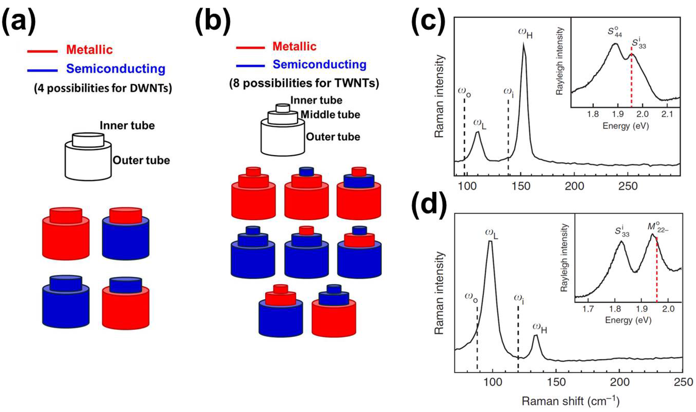
It is worth commenting that these multi-walled systems bring the advantage of mixing semiconducting (S) and metallic species (M), which extends the range of applications of DWNTs and TWNTs [39,40,41,42,43,44,45,46,47,48,49,50,51,52,53]. Moreover, the effectiveness of this mixing is directly related to the van der Waals forces mediating the interlayer interactions. In other words, for weak IL interactions, the tubes composing the multi-walled systems would behave independently of each other [30,31,32,33,34,35,36,37,38,54,55]. In fact, DWNTs can show up in four different flavors (inner tube@outer tube), as shown in Figure 3a, while TWNTs present eight different flavors (inner tube@middle tube@outer tube), as depicted in Figure 3b. The DWNTs and TWNTs can be either commensurate (when symmetry and periodicity in the multi-walled tubes exist) or incommensurate (when neither symmetry nor periodicity in the multi-walled systems exist). It had been common sense that incommensurate systems would not present IL interactions capable of changing the electronic and vibrational properties of the individual SWNT constituting the multi-walled carbon nanotubes [30,31,32,33,34,35,36,37,38,54,55]. On the other hand, commensurate systems would present IL interactions strong enough to perturb the electronic and vibrational structures of the SWNTs constituting the multi-walled tubes [30,31,32,33,34,35,36,37,38,54,55]. However, as discussed below, incommensurate tubes may present Moir e ´ patterns, and in these cases, the IL interactions cannot be neglected [54,55].
The effects caused by the IL interactions have been observed in the vibrational structures of both DWNTs and TWNTs. Liu et al. [56] experimentally demonstrated the IL effect on the coupling of the radial breathing mode (RBM) frequencies of each individual nanotube constituting the DWNT systems that were measured, as shown in Figure 3c,d. Their measurements show that coupling between the RBM of each constituting SWNT needs to be interpreted as symmetric and anti-symmetric combinations of the two pristine frequencies, which can be modeled taking into account a simple classical spring-mass system [56]. They also observed quantum interference effects in Raman scattering RBM intensities, which were also explained by considering the IL coupling between the two SWNTs composing the DWNTs systems [56]. Hirschmann et al. [57,58,59] demonstrated the influence of the van der Waals interactions in the phonon spectra of TWNT systems, both in bundle and isolated species. Through the analysis of changes in the RBM frequencies, G-band frequencies and the G frequencies, they showed that semiconducting tubes are often more affected by the IL interactions than metallic tubes, suggesting a metallicity-dependent shielding phenomena in these multi-walled systems. It was also demonstrated that these IL interactions are dependent on the curvature of the tubes, which is higher for small-diameter tubes (ranging around 1 nm) than for large-diameter tubes.
Recently, Liu et al. [55] observed shifts in the resonance energies of incommensurate DWNT systems, which were related to the IL interactions present in those DWNTs, as shown in Figure 4a,b. This was the first measurement suggesting that Moir e ´ patterns were formed for certain configurations of inner@outer tubes in DWNT systems. These experimental results were explained by Koshino et al. [54] in their theoretical work, which shows that DWNT systems indeed present Moir e ´ patterns for certain chiral angle combinations between the SWNTs constituting the DWNTs. These DWNTs can be described in terms of supercells, and in these cases, the IL interactions are strong enough to cause changes in the electronic properties of each constituent SWNT within a DWNT system (see Figure 4c).
Lambin et al. [32] studied several different DWNTs systems, and they found that in incommensurate M@S DWNTs the electronic density of states of the semiconducting tubes were weakly perturbed by its coupling to the inner metallic tubes, which presented a constant density of electronic states in the region of interest ( ± 1 eV). In commensurate M@S DWNTs, where the IL interactions are more effective, the VHS of the semiconducting tubes shift to higher energies, and an increase in the density of states in the bandgap is observed. For commensurate S@M DWNTs, the coupling between the inner semiconducting tube and the outer metallic tube modifies more strongly the semiconducting tube, which has its bandgap reduced due to the fact that its valence band blueshifts by 30 meV. The outer metallic tube remains basically unchanged [32]. Noffsinger and Cohen studied a commensurate M@M DWNT (more specifically, a ( 5 , 5 ) @ ( 10 , 10 ) ) and demonstrated that such a DWNT system behaves as its isolated counterparts. The reason is that the IL coupling slightly changes the electronic and vibrational properties of both the inner and the outer tube, but these changes balance out on average [60]. In their calculations, they also predicted superconductivity behavior for the M@M DWNT. It is important to note that superconductivity had been observed in MWNTs (with the number of walls greater than three) [61,62], but only recently was it observed in DWNTs [28,63,64]. Postupna et al. [65] performed calculations on S@S DWNTs, demonstrating the possibility for energy transfer mechanisms involving the two semiconducting tubes constituting the DWNT systems, and confirmed that the phenomenon of energy transfer strongly depends on the commensurability of the DWNTs, as well.
The mechanical properties of DWNTs and TWNTs are also addressed in the literature. Bacsa et al. [66] studied the mechanical properties of DWNTs under hydrostatic pressures using Raman spectroscopy. They found that the outer tubes protect the inner tubes from the effects of pressure. In fact, they found that the tangential stress depends on the diameter for the outer tubes, but it stays constant for the inner tubes. The results found by Bacsa et al. [66] are in agreement with the calculations performed by Natsuki et al. [67], which show that the outer tube indeed takes most of the hydrostatic pressure. Their calculation suggested that the IL interactions become negligible with increasing the pressure load, and this shields the inner tube in a DWNT system. Huang et al. [68] reported enhanced ductile behaviors in DWNTs and TWNTs submitted to axial tensions at temperatures above 2000 ° C. They explain the super-elongation observed in the tubular structure as being essentially related to creep deformations of the CNTs structures at high temperatures. Windle’s group confirms the same mechanical shielding of the inner tubes when multi-walled structures are submitted to strain/stress [69,70,71]. Recently, Alencar et al. [72] observed the same pressure screening effects for the innermost tubes in TWNT systems. In all of the experiments, the effects caused by the applied pressure loads did not demonstrate strong dependence with the ( n , m ) of the SWNTs constituting the multi-walled systems.
It is worth commenting that all of the possibilities mentioned above for both the DWNT and the TWNT species and their different metallicities bring a multitude of combinations of electronic and vibrational structures, which are still in the infant stage of exploration. Indeed, the majority of the phenomena involving the IL interactions in DWNTs and TWNTs are still waiting for experimental confirmation. As discussed in the next sections, the capability of synthesizing better DWNT and TWNT samples may open the doors for a deeper understanding of how the IL interactions affect these few-walled systems, and it may also broaden the research opportunities involving these hybrid systems.

2. Synthesis and Characterization of DWNTs

DWNTs are mainly produced by three different methods, such as arc discharge, catalytic chemical vapor deposition and the thermal treatment of pea pods (i.e., SWNTs encapsulating fullerenes). For the arc discharge method and the catalytic chemical vapor deposition (CCVD) method, the concepts of the synthesis are similar. By either carbon evaporation or using a carbon precursor with the decomposition method, carbon sources, such as graphite- or carbon-containing molecules, are decomposed into small fragments, and this is followed by the formation of an sp 2 carbon fibrous material due to the catalytic effect of metal nanoparticles. The last method listed above is based on the chemical reaction of confined molecules within the confined hollow space of the SWNTs.

2.1. The Arc Discharge Method

The arc discharge method was developed for the synthesis of fullerenes. However, in 1991, Iijima [1] discovered multi-walled carbon nanotubes (MWNTs) in the carbon soot at the end of an electrode (graphite rod), which was in a different place from where the fullerenes he was preparing were found. The synthetic apparatus used for the arc discharge method is simple, and the experimental parameters are not as numerous as for the CCVD method; this method therefore exhibits high reproducibility. In this method, a pair of carbon rods (usually made as a composite of graphite and metal nanoparticles) is placed in a vacuum chamber with a small gap, and then, a high voltage is applied over the gap in order to generate a plasma. By using a high temperature plasma, the carbon rod is partially vaporized, and CNTs are formed by the catalytic effect of the metal nanoparticles. In this growth method, the CNT growth occurs at a higher temperature than by the other methods for the preparation of DWNTs, such as the CCVD method. By the annealing of molecules encapsulated with the SWNT, it is widely accepted that the arc discharge-produced CNTs exhibit high crystallinity and low defect density [21,73,74,75,76,77,78,79,80,81,82,83]. While arc discharge-produced DWNTs exhibit a high oxidation temperature close to 800 ° C, the defect healing at high temperature was proposed as a justification for the high quality product outcomes [73,74]. In contrast to the high crystallinity of DWNTs, the high temperature also leads to the formation of highly graphitized non-CNT carbon impurities, which are difficult to remove by a simple purification process, such as oxidation and/or acid treatments, rather than the formation of amorphous carbons. Several carbon materials other than graphite can be used as carbon sources for CNTs. For example, Chen et al. [75] used carbon black as a carbon source for arc discharge-based DWNTs’ growth. It was found that the structural features of the carbon black, which correspond to the presence of the curvature induced by the heptagon and pentagon, are favored to increase the concentration of carbon species at the time of the arc discharge. The preparation of DWNTs from MWNT/carbon nanofiber (CNF) and fullerene waste has also been reported [76,77]. The use of MWNT/carbon nanofibers as carbon feedstock in the arc-discharge method converts about 80% of the carbon feedstock in high quality DWNTs with outer diameters ranging from 1.75–4.78 nm and inner diameters ranging from 1.06–3.93 nm [76]. On the other hand, the DWNTs produced from fullerene waste present outer tube diameters ranging from 1.50–5.00 nm and inner tube diameters ranging from 2.00–6.00 nm [77]. Although the DWNTs produced are also of high quality, there is no information on how much fullerene waste was actually converted in DWNTs. However, the authors reported that the purification process of the samples produced is easier when fullerene waste is used as a carbon source [77].
The addition of a promoter can increase the yield and the selectivity of DWNTs relative to other carbon forms, and even until now, these effects have not been well understood. Sulfur has been used as a promoter for the growth of carbon fibers (CF) [78,79]. By introducing sulfur as a promoter, Hutchison et al. [80] reported for the first time the selective growth of DWNTs, using the arc discharge method. The effect of sulfur on the growth of DWNTs has been further investigated by Saito et al. [81] with various metal catalysts under different gas environments (H 2 , He and their mixtures). It was found that sulfur is effective only for iron-group metal catalysts, and the presence of H 2 is found to be important. When non-iron-group metal catalysts, such as yttrium or lanthanum, were used, no DWNT growth was observed [81]. Windle’s group has addressed the observation that sulfur forms a coating layer that involves the metal nanoparticles, and this coating limits carbon diffusion and segregation in the metal nanoparticle surface [78]. Qiu et al. [82] demonstrated that the addition of potassium chloride improved the yield of CNTs and the selectivity of DWNTs. The yield of the CNT amount increased by five-fold, and the selectivity of DWNTs increased from 10% to over 50% after the optimization of the KCl content. While both KBr and NaCl also worked similarly as KCl, halogens seemed to play a key role in increasing the yield of CNT growth, as well as the selectivity of DWNTs during the synthesis reaction [83]. It was proposed that chloride (or halogens generally) lead to the formation of aromatic carbon species, which are easily transformed into CNT walls or cap structures.

2.2. The Catalytic Chemical Vapor Deposition Method

The catalytic chemical vapor deposition (CCVD) method has been used for the preparation of SWNTs, DWNTs and MWNTs. The main idea of the CCVD method is as follows: decompose the carbon precursor into small carbon species by applying heat (either by self-thermal decomposition or by catalytic dehydration at the catalyst surface); carbon species adsorb onto the catalyst surface, diffuse onto the surface of a catalyst metal nanoparticle, followed by the formation of a solid solution; saturated carbons precipitate from the catalyst metal nanoparticle and then simultaneously form a cap structure as the initiation of the CNT growth; the structure changes from the cap to a cylinder as the growth continues. This CCVD method involves various reactions; thus, usually, amorphous carbons, SWNTs and MWNTs are found as impurities besides DWNTs. Although the system for CCVD growth is quite simple, it is found that there are many parameters that can be controlled from the catalyst preparation all the way through the CCVD reaction. It was found that small variations in the details of these growth parameters sensitively change the catalytic reaction, as well as the resulting CNT structure. Therefore, selective growth of CNTs is still challenging. There are two different methods, which correspond to the “supported catalyst” method and the “floating catalyst” method for CCVD growth. To achieve selective growth of CNTs with a certain number of walls, the diameter of the metal nanoparticle needs to be precisely controlled prior to the synthesis reaction, since the catalyst metal nanoparticles with different diameters yield CNTs with different diameters and numbers of layers, depending on the CNT diameter. The desired addition of promoter is another way to control the layer number of CNTs. The highly selective growth of DWNTs has also been reported by several groups using different synthesis conditions (Table 1).

2.2.1. The Supported Catalyst Method

For CNT growth, transition metal nanoparticles, including Fe, Ni, Co and their binary alloys, have been frequently used as catalyst metal nanoparticles. In the case of the supported catalyst method, metal nanoparticle catalysts are prepared either by a chemical technique (chemical synthesis, impregnation, combustion, etc.) or a physical deposition technique (sputtering, e-beam/thermal deposition, etc.). The diameter of the metal nanoparticles is controlled by the conditions used for the catalyst preparation, and the prepared metal nanoparticles are supported on an oxide substrate (ex. SiO 2 , MgO, Al 2 O 3 ) to prevent aggregation during the heating process prior to the synthesis reaction. Both porous powder and planar substrates are used as supporting materials for CNTs’ synthesis. Within this method, DWNTs have been selectively prepared by optimizing the diameter of the metal nanoparticles, as well as the parameters of the synthesis reaction.
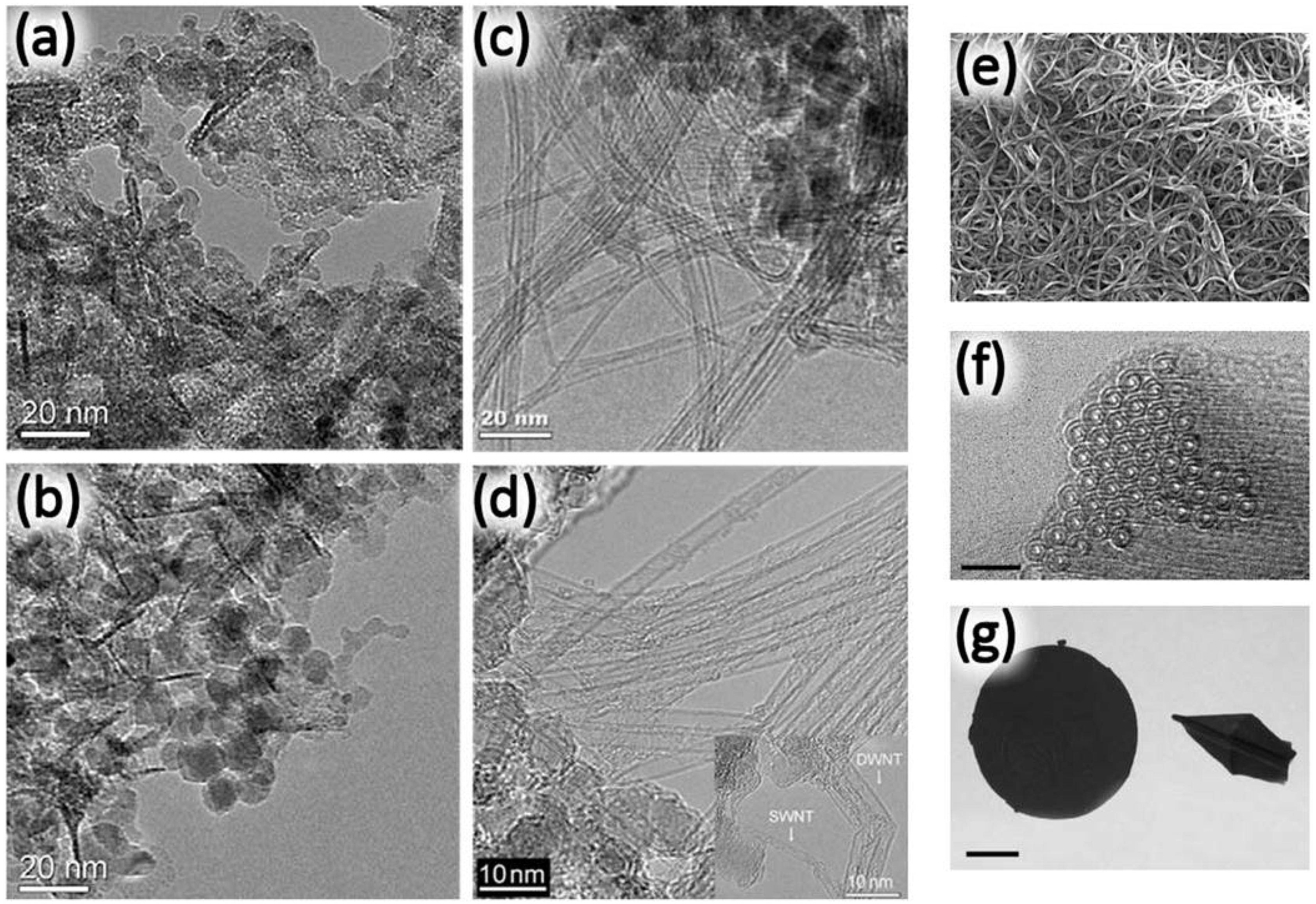
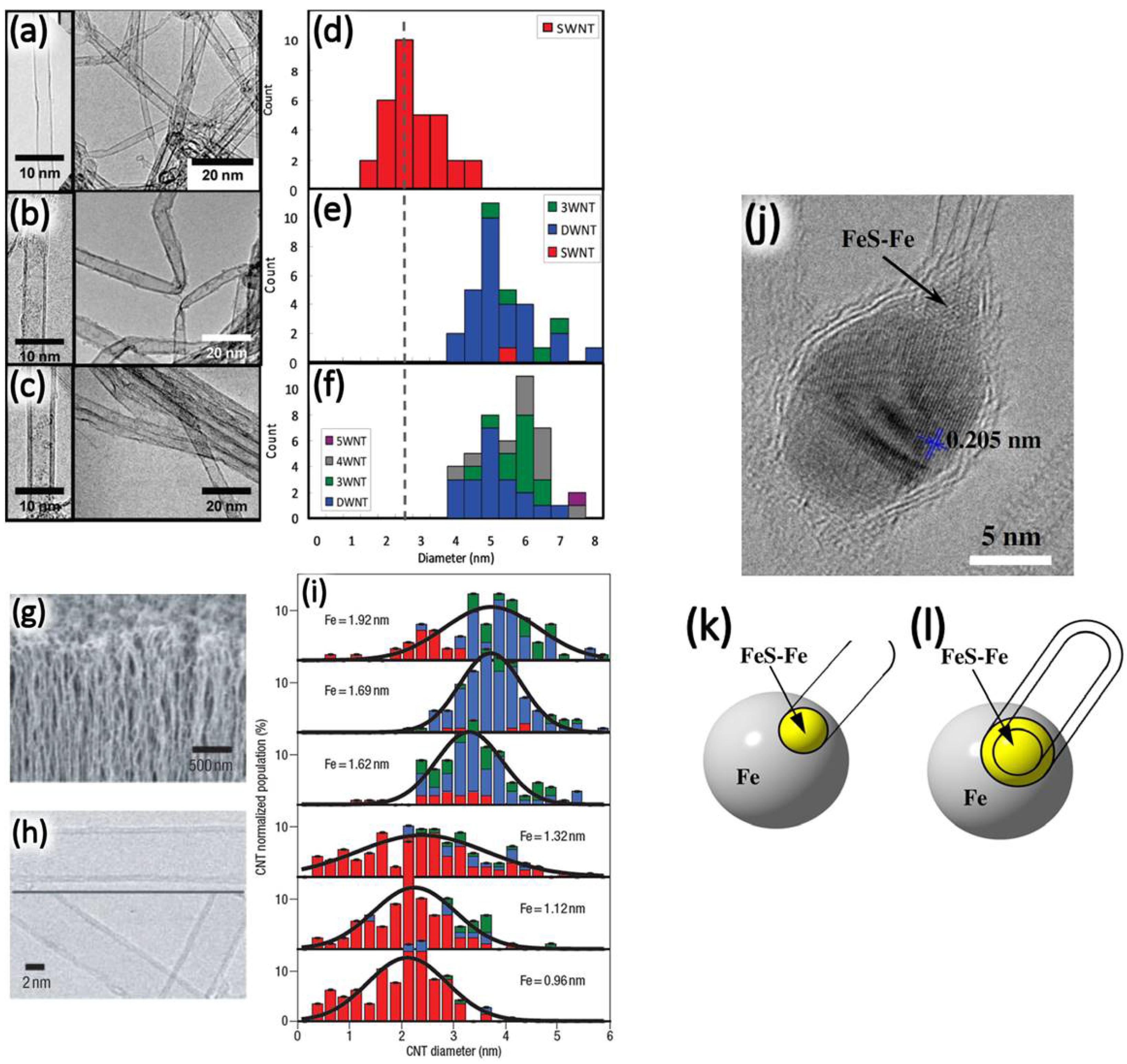
In the case of metal nanoparticles on a porous support, a chemical controlling method is frequently used. Chemical synthesis is the one of chemical control methods, and the metal nanoparticles are prepared by chemical reaction and using a metal catalyst precursor and a capping agent to obtain a finite growth time for the nanoparticles [100,114]. The diameter selected for the metal nanoparticle is related to the desired CNT diameter and the number of layers of the CNT. Ago et al. [125] investigated the interaction of metal (Fe) nanoparticles and the supporting material (MgO) for the growth. In this method, Fe nanoparticles are prepared by thermal decomposition using iron pentacarbonyl (Fe(CO) 5 ) as a precursor and oleic acid as a capping agent. It was found that MgO and Fe nanoparticles interact strongly, and thus, the Fe nanoparticles keep a smaller diameter at the CNT synthesis temperature. Because of the strong interaction between FeOx and MgO, the agglomeration of catalyst particles was highly suppressed. Diffusion of Mg and Fe occurs in the temperature range between 500 °C and 900 ° C, and then, this phenomena reduces the iron oxide particle and, thereby, moderates the size of the Fe nanoparticle to be suitable for the thinner CNT growth (SWNTs and DWNTs). Smaller Fe nanoparticles (1.6 or 2.8 nm) resulted in SWNTs’ growth, and a slightly larger Fe nanoparticle (4.5 nm) exhibited DWNTs’ growth, whereas a 6.4-nm or larger Fe nanoparticle did not grow any CNTs. Ago et al. [100] further investigated the effect of the diameter of Fe nanoparticles on CNTs’ growth. Both the inner and outer tube diameter distribution of the DWNTs was controlled by the diameter of the Fe nanoparticle. Fe nanoparticles are prepared by means of the thermal decomposition of Fe(CO) 5 , and oleic acid was used as the surface capping agent. The size of the nanoparticles was controlled to be 4 nm (Figure 5a) and 10 nm (Figure 5b) by the molar ratio of Fe(CO) 5 and oleic acid. The prepared Fe nanoparticles are here supported on MgO. Both catalysts yielded DWNTs with high selectivity up to 80%, but the observed catalyst nanoparticle after the CVD reaction exhibited a smaller size than its original size (Figure 5c,d). The Fe nanoparticles with a diameter of 4 nm and 10 nm produced DWNTs with an inner diameter of 0.91 and 1.42 nm and an outer diameter of 1.68 and 2.19 nm, respectively.
A simple impregnation/precipitation technique was also used for the preparation of the catalyst. It is possible to control the density of the metal nanoparticle by changing the ratio of the amount of metal nanoparticles and the supporting material. Various binary catalysts were investigated by Hiraoka et al. [98] for DWNT growth over Co-Fe, Co-Ni, Co-V, Co-Cr and Co-Mn supported on a zeolite substrate. The Co-Fe binary catalyst yielded a high selectivity of DWNTs, whereas other catalysts exhibit a low yield of DWNTs. In order to achieve a high selectivity of DWNT growth, the physicochemical properties of the supporting material is also important, since the interaction between the nanoparticles and the supporting material plays an important role during the heating process. The catalyst preparation method affects the diameter distribution of the metal nanoparticles, and it therefore also affects the selectivity of the chirality and metallicity of the DWNTs. Flahaut et al. [96] reported the selective growth of DWNTs (in comparison to other CNT versions) over the Mg 1 x y Co x Mo y O catalyst. The catalyst for DWNTs’ growth was prepared by a simple combustion method using urea and citric acid as fuel. Compared to the urea-based combustion process, the citric acid-based combustion process led to the formation of a homogeneous catalyst. Thus, the selectivity of DWNTs was high for the citric acid-based catalyst. They also mentioned that by changing the catalyst preparation conditions, they can prepare a mixture of DWNTs and TWNTs. Zhang et al. improved the yield and the purity of the DWNTs by introducing small amounts of Al into the Fe/MgO system [85]. As a result of the phase separation that occurred due to the Al addition, the crystalline size of the MgO decreased as the Al content increased, and therefore, the dispersity of the Fe nanoparticles was improved. The improved dispersion of Fe nanoparticle resulted in a higher yield and higher purity for DWNTs. Both the physical properties and the chemical properties of the silica-based supporting material were investigated [85].
Ramesh et al. [99] have used the Fe/Co nanoparticles in connection with different silica-based porous supporting substrates and they have investigated the relationship between the pore structure/surface property of the supporting substrate material and the selectivity of the DWNT growth process. A sol-gel-based microporous silica and a hydrothermal synthesis-based mesoporous silica were used. It was found that the number of layers of CNTs varied depending sensitively on the synthesis temperature. When the synthesis was carried out at 800 ° C, 90% of the product was SWNTs. In the case of mesoporous silica, the yield of DWNTs increased up to 80% with increasing synthesis temperature, whereas the yield of DWNTs saturated and decreased when microporous silica was used. Moreover, it was found that the difference in the acidity of the supporting material also affects the selectivity of DWNTs relative to other carbon nanostructures when the pore structure was the same, and weakly acidic mesoporous silica yielded DWNTs preferentially. Qi et al. [102] found that the commercially-available FeSi 2 powder worked as a catalyst for the selective growth of DWNTs. After proper oxidation of the FeSi 2 powder prior to CNT growth, oxidation induced Fe 2 O 3 formation occurred on top of the FeSi 2 particle, sitting on the SiO 2 substrates. Thus, the treatment of the Fe nanoparticles produced by the reduction to form uniformly nucleated Fe 2 O 3 under proper environmental conditions yielded a uniform DWNT structure.
As discussed above in the section describing the arc discharge method, promoters are also used to improve both the yield and the selectivity of DWNTs relative to other carbon nanostructures. Mo is frequently used to improve the preference for DWNT production during the growth process [92,103,104,106]. Flahaut et al. [92] reported that the presence of Mo improved the yield and increased the selectivity of DWNTs, but the detailed role of Mo in the growth process remained unclear. Their method increased the DWNT selectivity from less than 50% to over 80% by Mo addition [92]. Matsumoto et al. [106] soon thereafter achieved highly selective growth of DWNTs using a Co-Fe-Mo catalyst. The optimized condition Co:Fe:Mo = 2.5:1.0:3.5 delivered essentially a 100% selectivity of DWNTs after the purification process by oxidation at 700 ° C in air. When the Mo content was below the aforementioned optimum condition, larger diameter DWNTs and MWNTs were obtained. The other important factor was the Fe:Co ratio, whereby a lower Co content increased the content of TWNTs from 0 %–45 %, whereas the diameter of the inner-most tube remained unchanged.

Effect of Mo Addition

The effect of Mo addition in the Fe-Mo/MgO system was investigated by Biris et al. [105]. Two functions were proposed for Mo addition upon the selective growth of DWNTs: (1) a large particle of Mo on MgO can provide a secondary support for Fe nanoparticle; (2) the breakup the hydrocarbon molecules for efficient carbon precursor conversion prior to CNTs synthesis reaction. The detailed methane conversion behavior over Fe-Mo/MgO was investigated by Ago et al. [126], and the addition of a small amount Mo improved the conversion efficiency. For the Mo addition, the alloy formation with Fe, Co or MgO is not necessary to improve the yield and the selectivity of DWNT growth. Endo et al. [104] used Mo/Al 2 O 3 as a conditioning catalyst, and it was placed separate from the CNT growth catalyst (Fe/MgO). In the case of the presence of the conditioning catalyst, >95% of the high DWNT selectivity was achieved after the optimum purification process (Figure 5e–f). Moreover, since the optimization of the conditioning catalyst was separated from the optimization of the CNT growth catalyst, simple oxidation in air and hydrochloric acid (HCl) treatment removed most of the impurities, such as amorphous carbon, Fe nanoparticles and MgO support; this removal of impurities would be useful for commercializing the growth of DWNTs for device applications. The highly bundled structure of DWNTs realized by the narrow diameter distribution and the low amount of impurity enabled DWNTs to form buckypaper by a filtration technique (Figure 5g). The obtained DWNTs buckypaper was tough enough to fold into an origami structure.

Effect of Water

In 2004, the effect of water as a reaction enhancer, which removes the carbon coating layer on the metal nanoparticle catalyst and thereby prolongs the lifetime of the catalyst, was reported, and the detailed growth mechanism was discussed later [127,128]. Later research revealed that not only water, but also oxygen molecules act similarly. Futaba et al. [115] investigated the effect of the reaction enhancer on the number of layers of CNTs (Figure 6a–f). Similar to water, it was found that a small amount (hundreds of ppm order of magnitude) of any oxygen-containing molecular form acts as a reaction enhancer. Furthermore, with an enhancer containing aromatic rings, the control over the number of walls in the carbon nanotube structure was observed. Namely, with methyl-benzoate as a reaction enhancer, DWNTs were preferably grown after the synthesis reaction with a high selectivity of 84% without any post-purification (Figure 6b–e). While the other molecular reaction enhancer, benzaldehyde, also yielded MWNTs with a prolonged catalyst lifetime (Figure 6c–f), it was proposed that multilayer formation originates from the aromatic structure-based π-π interaction between dissociated reaction-enhancer molecules.
In the case where a planer substrate was used as a supporting material (such as SiO 2 /Si, Al 2 O 3 ), the resulting film of metal nanoparticles is usually deposited on the film by a physical method, such as sputtering, thermal evaporation, electron beam evaporation, etc. The layer number of CNTs is usually controlled by the thickness of the catalyst metal nanoparticle film. Yamada et al. [116] prepared a thin film of Fe, varying its thickness by the sputtering technique, and the synthesis reaction was carried out over the substrate. By using the water-assisted CVD process, 2.2 mm-long vertically-aligned DWNTs were grown with a selectivity as high as 85% (Figure 6g–h) [127]. The number of walls of the CNTs thus obtained was precisely controlled by the thickness of the Fe thin film, and this approach was used to get the optimum thickness for the selective growth of SWNTs and for DWNTs. When the thickness of the Fe film is below 1.2 nm, SWNTs were predominantly grown, whereas DWNTs were predominantly grown when the thickness was thicker than 1.6 nm, with the transition region occurring between 1.2 nm and 1.6 nm (Figure 6i). This threshold sensitively varied when the purity of the sputtering target was changed, but the same trend was observed. The selective growth of DWNTs was also achieved by optimizing the Fe concentration of the carbon source [113].

2.2.2. The Floating Catalyst Method

In the case of the floating catalyst method, a metal catalyst precursor containing a solution is atomized by spraying or ultra-sonication, or the metal catalyst precursor powder is simply sublimated by heat, and then, the generated aerosol/vapor is transferred into the heated reaction zone by a carrier gas. The diameter and the number of walls of the resulting CNTs are strongly related to the composition of the precursor solution, the atomizing/vaporizing conditions and the reaction conditions, and the desired DWNTs are successfully prepared by optimizing these conditions.
Sulfur is used as an additive for the CNT synthesis to improve the yield of CNTs, as well as for controlling the number of walls. In the case of the floating catalyst method, it is not easy to introduce an oxide particle into the reaction zone in the gas phase; sulfur is commonly used as a sensitive agent for controlling the number of walls during DWNT synthesis. Wei et al. [120] reported that when a small amount of sulfur (10 at % of Fe) is added into the precursor materials, mostly DWNTs (80%) were grown as the major CNT product, whereas SWNTs (95%) were mainly produced for the conditions without the sulfur additive. By increasing the concentration of sulfur, both the CNT diameter and number of layers increased. A growth mechanism for this route to CNT growth by the sulfur-assisted method was proposed. The nucleation of the CNT is activated at the location of the eutectic FeS-Fe on the surface of Fe nanoparticles (Figure 6j–l). Since by this floating catalyst method it is possible to supply catalyst precursor continuously, the continuous production of DWNTs can be achieved. Using this method, Li et al. [129] firstly reported the continuous production of SWNTs. Soon thereafter, the continuous production of DWNTs was also reported by optimizing the temperature, precursor composition (both of the metal catalyst precursor and the sulfur/sulfur-containing molecule), as well as the aerosol generation conditions and reaction conditions [121,122,123].

2.2.3. Annealing of Confined Molecules inside SWNTs

The annealing of confined molecules inside a SWNT provides a different concept for producing DWNTs. Since a CNT is a tubular carbon material, there is a hollow empty space inside the CNT. This empty space can be usefully filled with some small molecules or atoms, and then, the effect of the encapsulation of various molecules and atoms by SWNTs can be studied. The “pea pod” was first reported and named for the hybridized structure of SWNTs encapsulating fullerenes (such as C 60 [130], C 70 [131, etc.) (Figure 7a). When external stimuli, such as heat [132], an electron beam [133] and UV light [134], were applied to the pea pod (Figure 7b), the C 60 molecules inside the SWNTs partially coalesced with neighboring C 60 molecules to eventually be transformed thereby forming the inner tube of a DWNT (Figure 7c). Besides fullerenes, other molecules also worked as precursors for forming the inner tube of DWNTs. Successful DWNT formation by thermal annealing or electron beam irradiation of SWNTs with encapsulated molecules, such as coronene (C 24 H 12 ) [135], anthracene (C 14 H 10 ) [136], picene (C 22 H 14 ) [137], pentacene (C 22 H 14 ) [137], Perylenetetracarboxylic dianhydride (PTDCA) (C 24 H 8 O 6 ) [137,138], ferrocene (FeCp 2 ) [139,140,141], tris(cyclopentadienyl) gadolinium (GdCp 3 ) [139,140] and organometallic fullerene complexes [142], was reported, as well.
Lim et al. [137] found that there are two different intermediate states of the inner tube depending on the encapsulated molecular species. In the case of PTCDA, graphene nanoribbon-like intermediates were formed during annealing (Figure 7d), whereas fullerenes, picene and pentacene formed deformed fullerene-like intermediates prior to DWNT formation (Figure 7e). The graphene nanoribbon-like intermediates are possible because the oxygen-terminated edges of PTCDA molecules release their oxygen, to generate CO or CO 2 molecules upon annealing, and the remaining perylene tetraradicals are merged into the graphene nanoribbon structure. The helically-twisted single or double graphene nanoribbons are further merged into an inner tube upon continuous annealing. Ferrocene (FeCp 2 ), which is commonly used for CNT growth as a metal catalyst precursor for the catalytic chemical vapor deposition (CCVD) floating catalyst method, also works as a precursor for the inner tube growth [139,140,141]. In the case of ferrocene, the inner tube formed at a low temperature of 600 ° C [139]. It was proposed that the formation mechanism of the inner tube is different from the fullerene coalescence and graphene nanoribbon merging methods, since these coalescence-derived inner tube formation methods do not occur at this low temperature. The encapsulated ferrocene (Figure 7f) would first decompose into iron carbide (Fe 3 C, Figure 7g), which could be responsible for the catalytic growth of these inner tubes.
The chirality distribution of the encapsulated molecules-derived inner tube of the DWNT is dependent on the choice of the precursor molecules [137]. Even when fullerenes with a similar structure, such as C 60 and C 70 , are used as the precursor, these molecules produce inner tubes with a different chirality distribution. The C 60 -derived inner tubes tend to be ( 6 , 4 ) and ( 6 , 5 ) tubes, whereas the C 70 -, ferrocene- and PTCDA-derived inner tubes tend to be ( 6 , 4 ) or ( 9 , 1 ), ( 6 , 5 ) or ( 8 , 1 ) and ( 7 , 2 ) tubes, respectively.

2.3. Brief Summary: Synthesis of DWNTs

As discussed above, it seems that a recipe to controllably-produce DWNTs relative to their diameter range, metallicities, flavors and chiralities does not yet exist. Each approach discussed above leads to different outcomes, which present advantages and disadvantages. The arc-discharge method has the advantage of producing ultra-high quality DWNTs, but it has the disadvantages of producing many other forms of carbon materials, and the samples that are grown via this method are very hard to purify. The CCVD method can be applied using different approaches: the support catalyst method and the floating catalyst method. The support catalyst method has the advantage of selecting the DWNT diameter range, metallicity and number of walls by controlling the properties of the metal nanoparticles used as precursors. On the other hand, the floating catalyst method does not provide as good control over the diameter range and metallicity, but provides a better control over the number of walls of the carbon nanotube when sulfur is added to the growth reaction zone. Moreover, in this approach, the precursor is supplied continuously, which results in a continuous production of DWNTs. Both methods have disadvantages inherent to the chemical vapor deposition methods: any small change in the growth parameters will dramatically change the growth outcome, and the quality of the tubes is lower in comparison to the pea pod-derived method and the arc-discharge method. Finally, the pea pod-derived method produces high quality DWNTs and is a good candidate to producing chirality-specific DWNTs. However, the method produces DWNTs in a limited range of diameters with the outer tube diameter always larger than 1 nm, which is a necessary condition to encapsulate molecules that will later become the inner tube. The authors also recommend that the readers read reference [143], which is a very good complementary reference about many aspects of DWNTs’ production and purification.

3. Synthesis and Characterization of TWNTs

Unlike the synthesis of DWNTs, the synthesis of TWNTs remains a more challenging topic, and there are only a few reports approaching this theme. In the case of DWNT synthesis, the number of layers is controlled by either the precise control of the metal nanoparticles diameter, synthesis conditions or the addition of a growth promoter, such as Mo, S and O. However, these tuning approaches introduce instability into the synthesis system while increasing the degree of tuning. Therefore, controllability tends to become fuzzier when the focus is shifted from DWNT to TWNT synthesis. Moreover, in the case of TWNT synthesis, it is difficult to remove DWNTs mixed with TWNTs, since the difference in physicochemical properties between them is smaller than that between SWNTs and DWNTs.
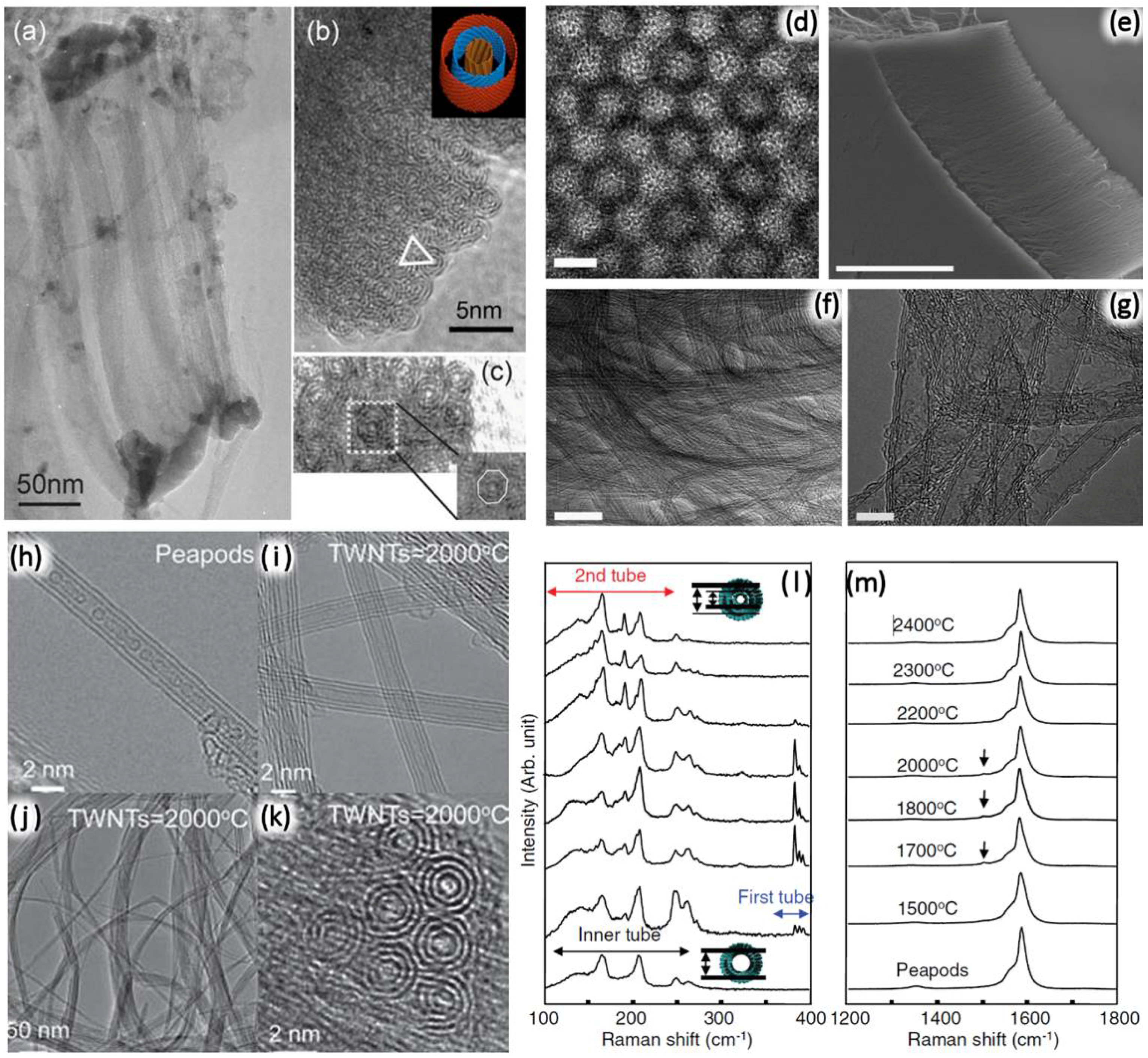
To the best of our knowledge, Yu et al. [144] were the first to observe a large amount of TWNT growth (Figure 8a–c). The TWNTs were found in a bundle structure with a ring shape where each TWNT was closely packed into a triangular configuration (Figure 8b). Only 10% of all of the ring structure was composed of only TWNTs. The CNT growth is quite sensitive to the size of the metal catalyst and/or the synthesis conditions, suggesting that the reaction window for the selective growth of TWNTs could be narrow. To advance this research direction, the growth kinetics of long TWNTs was investigated by Wen et al. [145], and 100 mm-long TWNTs were grown on a Si substrate by a gas flow-directed CVD method [145]. The reaction window for the preferential TWNT growth was narrow, as well. When the synthesis temperature was increased by 20 ° C or 40 ° C, the yield of SWNT and DWNT was dramatically increased in the intended TWNT growth, and then, the selectivity of the TWNT growth was decreased down to 30% within typical sample growth runs. It was demonstrated when the TWNT growth condition was in a narrow reaction window, the growth of TWNTs was stable [145]. The CNTs with chiral angles close to 30 ° (close to the armchair CNT) showed a stable structure over 60 mm of length, and the growth rate of the CNT was about 16% higher than for the other lengths and for the SWNTs species. Notoriously, TWNTs with lengths less than 30 mm presented smaller chiral angles (ranging from 10–20 ° ) and four dominant flavors: S@S@S, M@S@M, S@S@M, S@M@S. For TWNTs with lengths more than 30 mm, chiral angles ranging from 20–30 ° were preferred, and only one flavor was observed: S@S@S [145]. For all of the lengths, the differences between the chiral angles for the nanotubes composing the TWNTs were around 6.5 ° .
Yamada et al. [116] achieved selective growth of SWNTs and DWNTs by controlling the thickness of the metal catalyst film. This suggested that it could be possible to synthesize TWNTs selectively by simultaneously optimizing the metal catalyst film thickness, as well as the reaction conditions. To increase TWNT synthesis yields, Chiang et al. [146] synthesized vertically-aligned TWNT films from thickness-controlled Fe film deposited on a Si substrate. It was found that a precisely controlled 3 nm-thick Fe film yielded ∼8 nm-diameter TWNTs with a TWNT selectivity as high as ∼60%. Chemical control of catalytic metal nanoparticles was also achieved to benefit selectivity and TWNT quality. In this context, Baliyan et al. [147] used a microwave plasma-enhanced CVD (PECVD) system and engineered mono-dispersed hollow nanoparticles (HNPs) of Fe 3 O 4 (Figure 8d) as a catalyst for studying TWNTs’ growth. Because the shrinkage of the HNPs during the heating process avoided the aggregation of the catalyst nanoparticles, then dense, vertically-aligned CNTs with a uniform internal diameter of 4.86 nm were grown on the Si substrate (Figure 8e–g). With this approach, 83% of grown CNTs have three concentric walls (TWNTs), and the area density of the CNTs was 0.6 × 10 12 cm 2 . Taki et al. [148] achieved the selective growth of TWNTs by means of a newly-developed radiation-heated catalytic chemical vapor deposition (CCVD) method. As mentioned before, the number of walls of CNTs varies sensitively depending on the metal catalyst particle diameter. Therefore, to achieve selective growth of DWNTs or TWNTs, a narrow catalyst diameter distribution is important. The thin film of catalyst metal nanoparticles with a narrow diameter distribution was prepared by dip-coating precursor solution onto a quartz glass [148]. The diameter distribution was well controlled by optimizing the concentration of the Co and Mo precursors, which was varied from 0.01–0.10 wt % in an ethanol solution in this study [148]. The catalyst nanoparticles where prepared on a Si substrate and were heated rapidly by infrared irradiation. This rapid heating process suppressed the effect of aggregation, and thus, the diameter distribution of metal nanoparticles remained narrow, which also improved the selectivity of the number of walls. SWNTs, DWNTs and TWNTs were selectively grown on the substrate prepared from 0.01, 0.03 and 0.07 wt % precursor solution respectively, and this selectivity for optimizing the conditions was reported to be 100% (SWNTs), 88% (DWNTs) and 76% (TWNTs), respectively, without any purification process. They also tried to grow wall number-selected CNTs by the conventional CVD techniques. However, the diameter distribution was widened during the heating process in the case of the conventional CVD method; therefore, the SWNTs were also grown predominantly using this technique [148]. The effective catalyst size for the SWNTs, DWNTs and TWNTs thus produced were found to be 2–8 nm, 8–11 nm and 11–15 nm, respectively [148]. The authors claim that the layer numbers of CNTs can be precisely controlled by control of the diameter, thickness or active area of the metal catalyst [148]. However, an increase of the diameter or the film thickness of the metal catalyst usually enlarges the diameter of the inner-most tube of the CNTs as a side effect, so that it is difficult to synthesize TWNTs with the inner-most tube remaining small. Although CNTs lose their quantum effects with increasing diameter, the other synthesis route of TWNTs has also been explored, as they still present very interesting mechanical properties [2,148].

3.1. Annealing of Confined Molecules inside DWNTs

Muramatsu et al. prepared high quality TWNTs by introducing C 60 into DWNTs followed by high temperature annealing [149,150] and starting from CCVD-prepared high quality DWNTs [104]. In order to enlarge the DWNT diameters, high temperature annealing was carried out prior to C 60 encapsulation [149]. At a temperature of 2400 ° C, the diameter of both the inner tube and the outer tube of the DWNT increased via the coalescence mechanism [149]. After the annealing process, the inner tube diameter of the DWNT was in the range of 1.0–1.8 nm, which is wide enough for C 60 encapsulation. The DWNT and C 60 were sealed inside a glass ampoule under vacuum, and then, the glass ampoule was heated at 600 ° C for the C 60 encapsulation. Finally, a secondary high temperature heat treatment process (1500 °C–2000 ° C) transformed the DWNT-pea pod (Figure 8h) into TWNTs (Figure 8i–k) [149]. The diameter of the newly-generated inner-most tube was in the range of 0.4–1.0 nm, and the generation of an inner-most tube was confirmed by Raman spectroscopy (Figure 8l–m). Recently, Hirschmann et al. [57,58,59] used resonant Raman spectroscopy (RRS) to study in greater detail these fullerene-derived TWNTs in both bundles and isolated versions. In these studies, the authors confirmed the high-quality TWNT throughput of the fullerene-derived method reported by Muramatsu and co-authors [149]. The works by Hirschmann and co-authors also reported the first comprehensive studies on the vibrational properties of these high-quality TWNTs, connecting such properties with their SWNT and DWNT counterparts [57,58,59,151,152,153]. Table 2 summarizes the different synthesis conditions that produce TWNTs.

3.2. Brief Summary: Synthesis of TWNTs

In summary, while DWNTs can be readily produced via the arc-discharge method, the CCVD method and the pea pod-derived method, the production of TWNTs is definitively more challenging. To the best of the author’s knowledge, there is no arc-discharge method recipe that provides a reasonable outcome in terms of TWNT selectivity relative to other carbon materials produced during the growth process. The CCVD methods are good for producing DWNTs, but present a very narrow window of parameter tunability that leads to a highly selective TWNT production relative to other carbon materials. The attempts to use the CCVD method to grow TWNTs usually result in a mixing of DWNTs and TWNTs, which is not trivial to be separated due to similar physicochemical properties presented by both the DWNTs and the TWNTs. The most prominent method to grow TWNTs seems to be the pea pod-derived method, which produces TWNTs from large diameter DWNTs that have either C 60 or C 70 molecules encapsulated to form the innermost tube. This method produces high quality TWNTs with good selectivity relative to other carbon nano-products produced during the growth process.

4. Pea Pod-Derived Method: Advantages and Disadvantages

Pea pod-derived DWNTs and TWNTs have specific advantages and disadvantages over the DWNTs and TWNTs grown by the arc-discharge method and the CVD method [104,120,130,131,134,135,136,137,138,139,140,141,142,150]. One advantage is that the method of growing the multi-walled structures by thermally-treating pea pods makes it possible to obtain high-purity CNTs without contaminants, such as metallic impurities. Another advantage is that the diameter and chirality distributions of pea pod-derived DWNTs and TWNTs are narrower than the diameter and chirality distributions obtained via arc-discharge and CVD. This happens because the electronic structure of the constituent inner tubes is predominantly determined by the outer tubes, as well as by the high temperature observed during the thermal treatment. It is very interesting to note that the interlayer spacing in pea pod-derived structures strongly depends on the high temperatures achieved during the thermal treatment [104,120,130,131,134,135,136,137,138,139,140,141,142,150].
Therefore, this method is highly promising to synthesize DWNTs and TWNTs with specific metallicity configurations (e.g., S@M, M@S, S@S and M@M in the case of DWNTs) using metallic or semiconducting SWNTs as host materials under optimized synthetic conditions. Eventually, it will be possible to synthesize chirality-specific DWNTs and TWNTs using chirality-specific SWNTs as host materials and optimized thermal treatment conditions (e.g., temperature and environment of the growth process) [104,120,130,131,134,135,136,137,138,139,140,141,142,150]. However, the pea pod-derived method presents the following disadvantages: (1) it suffers from the limited filling ratio of fullerenes inside SWNTs, which leads to the formation of very short or disconnected inner tubes; (2) it has limited production capacity; (3) it relies upon high-cost ultra-crystalline arc-discharge-derived SWNTs (in the case of the DWNT synthesis) to serve as host materials; and (4) the method also depends on high-cost material processing techniques, as for example, the technique used to encapsulate the fullerene molecules and the high temperatures required during the thermal treatment [104,120,130,131,134,135,136,137,138,139,140,141,142,150].
This is likely why, intrinsically, the CVD method has been largely used to produce CNTs at an industrial scale. Indeed, the CVD method carries the disadvantage of producing lower quality samples, but on the other hand, it is a technique much cheaper to operate than the arc-discharge technique and the pea pod-derived technique. The commercially-available DWNTs are predominantly synthesized via the CVD method.

5. Applications Involving DWNTs and TWNTs

As we mentioned above, CNTs have been discussed as powerful materials for producing the next generation of electronic devices. Indeed, several applications were already tested, but not explored enough due to the limitations of synthesizing high quality few-walled carbon nanotubes, although this limitation no longer exists for SWNT synthesis, which has reached the state-of-the-art in chirality-specific production [154,155,156]. The use of DWNTs and TWNTs as interconnects, which usually represent 70% of the impedance of today’s integrated circuits, is considered to have the potential to play a key role in improving the performance of future integrated circuits. The successful use of CNTs relies on the number of CNT walls of the CNTs and also on the density of tubes making the interconnections. Dijon and co-authors in 2010 [157] approached this problem by synthesizing DWNTs and TWNTs directly on doped silicon utilizing a method called “integration in vias”, as shown in Figure 9a. Again, CNT growth has been identified as a major drawback in helping to control the species being grown, as well as the density and specific number of walls at the resulting carbon nanotube [157].
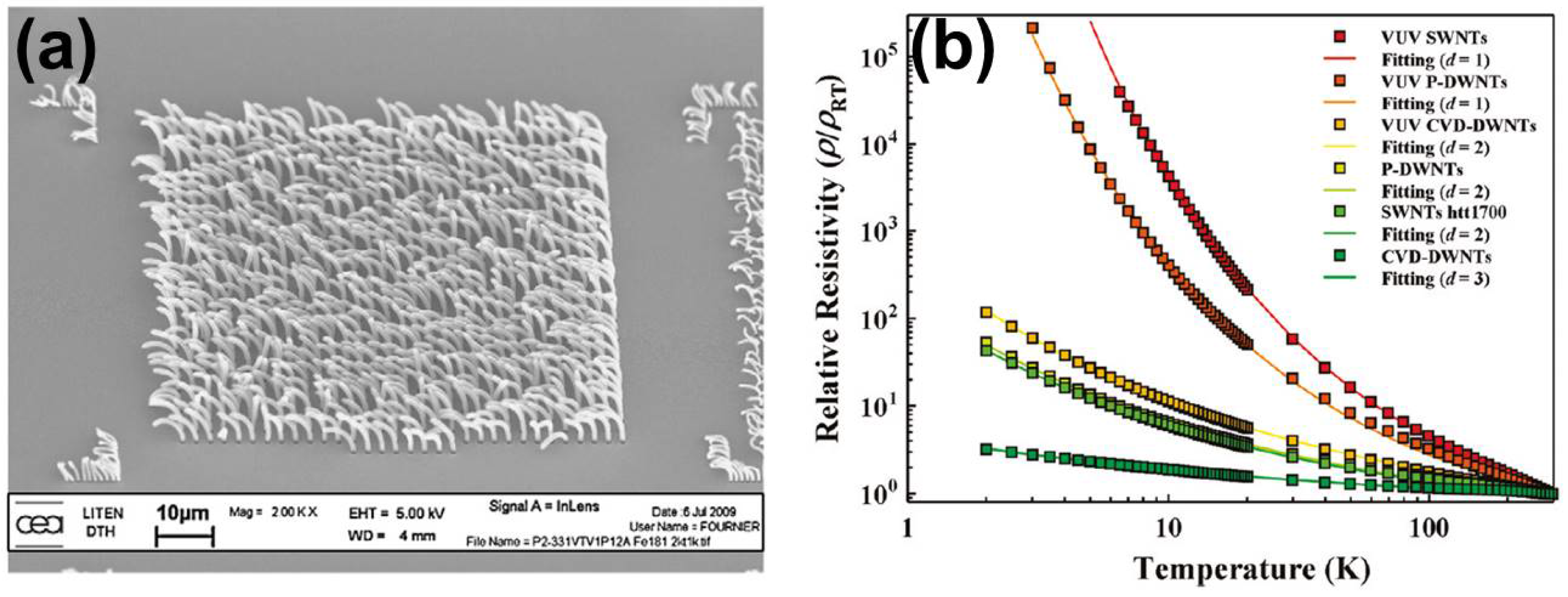
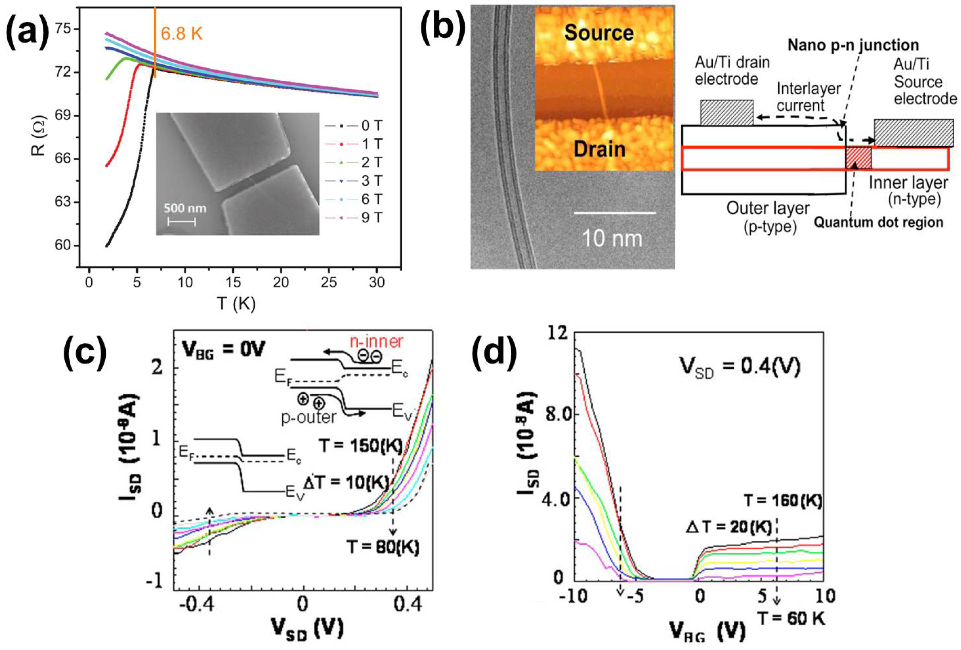
Double-walled carbon nanotubes have also been identified as materials with interesting electronic transport properties (such as chirality dependence and inner/outer tube selectivity) and superconductivity [158,159,160,161,162]. Fujisawa et al. [158], as shown in Figure 9b, investigated the transport properties in films containing pea pod-derived DWNTs and CVD DWNTs. They found that the synthesis technique matters to determine the performance of the films. Indeed, the lowest resistivity was found for films obtained from CVD-DWNTs. The resistivity was lower in CVD-DWNTs than in both SWNT and pea pod-derived DWNT films. The result was correlated with the total content of metallic tubes that the CVD-DWNT sample contains. According to their DWNT chirality analysis, the metallic content of the inner and outer tubes for pea pod-derived DWNTs was found to be 15% and 25%, whereas the corresponding values for the inner and the outer tubes of the CVD-DWNTs corresponded to 35% and 20%. The low metallic content in the inner tubes of the pea pod-DWNTs, as explained above, is related to their special growth conditions, such as their high temperature thermal treatment. Moreover, no significant difference in the electrical resistivities of SWNT films and the pea pod-DWNT films is observed, which indicates the predominant role of the outer tubes in the transport. The results demonstrated that conductive films of DWNTs can have their transport properties tailored by the method used to grow the DWNT systems [158]. Devices utilizing bundles of MWNTs, including DWNTs and TWNTs, also showed superconductivity behavior at low temperatures [28,61,62,63,64]. Shi et al. [28] measured devices containing bundles of DWNTs and observed clear signatures of supercurrents for temperatures below the average critical temperature of 6.8 K, as shown in Figure 10a, while Barzola-Quiquia et al. [63] observed superconductive behavior in their bundled DWNT samples for temperatures below the critical temperature of 15 K.
These systems, DWNTs, can be used to manufacture self-organized nano-Schottky junctions wherein one layer exhibits a semiconducting behavior and the other exhibits a metallic behavior [163]. These double-walled systems can also be used to fabricate nano-p-n junction devices wherein one SWNT exhibits a p-type semiconducting behavior and the other SWNT exhibits an n-type behavior [163]. These cylindrical nano-p-n junctions are designed so that electrode contacts are placed individually in each SWNT constituting the DWNT, as shown in Figure 10b. With this design, the IL interactions give rise to a measurable current flow [163]. Shimizu et al. [163] observed that the barrier heights at the nano-p-n junction in a device as the one shown in Figure 10b are different for electrons and holes, which is confirmed by the asymmetric (and unusual) ambipolar behavior of the devices, as observed in Figure 10c,d. In their work, they show that the ambipolar behavior that was observed could be addressed only by considering the transport between the constituent SWNTs, which is mediated by the IL interactions. The nano-p-n junctions are more likely to exist at the location where the carbon atoms in hexagonal lattices have the highest alignment at the interlayer space. In other words, their work suggests that the DWNTs need to be commensurate [163]. To the best knowledge of the authors, devices like the one described above have not been fabricated using TWNTs. It is worth mentioning that TWNTs would be natural candidates to build nano-p-n-p or nano-n-p-n junctions, which would allow the fabrication of cylindrical nano-transistors.
Nano-supercapacitors can also be fabricated with DWNTs [164,165,166]. Namely, Cooper et al. [166] used DNA-dispersed DWNTs to fabricate electrodes for supercapacitors. Their work demonstrates that the DNA-dispersed electrode films work much better than those made of DWNTs in bundles, and these electrodes double the capacitance obtained in films fabricated with pristine DWNTs. In the experiment, they measured a supercapacitance of about 67 F/g for the DNA-dispersed DWNTs films [166]. Chen et al. [164], on the other hand, used bromine-doped DWNTs to demonstrate the existence of a radial charge distribution within the positive carbon electrode of a cylindrical DWNT molecular capacitor. In these molecular capacitors, bromine acts as a radial gate, which mediates very different band filling effects on each SWNT constituting the DWNT system. They demonstrate that in such capacitors, the nanoscale electrostatics dominates over the quantum confinement inherent for these one-dimensional structures [164].
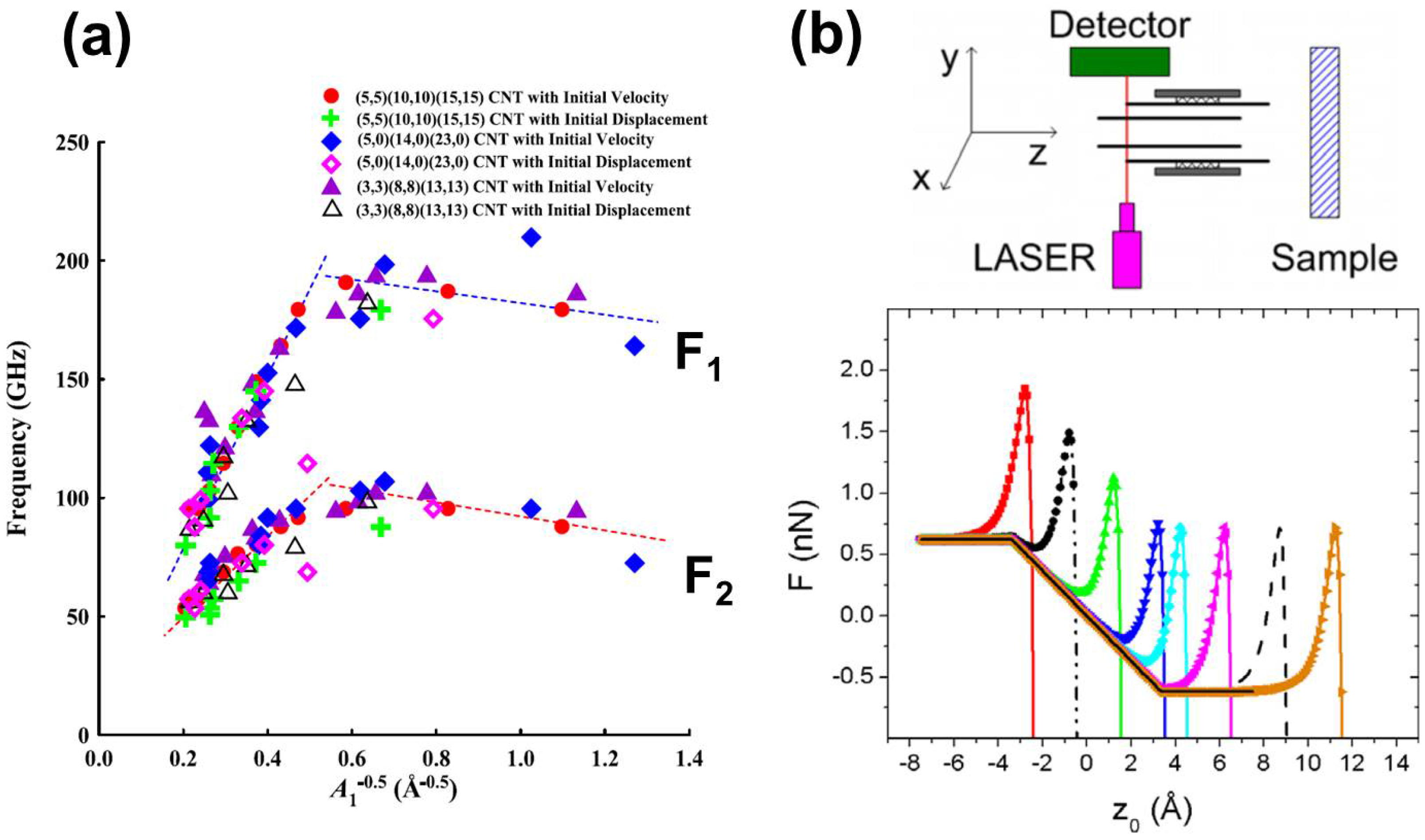
Multi-walled carbon nanotubes have been suggested as good platforms for fabricating oscillator devices [167,168,169,170,171,172]. Jiang’s group [167] proposed in their calculations that DWNTs and TWNTs are good candidates for functional nano-oscillators, where the number of walls, the metallicity and chiralities of the nanotubes composing the few-walled systems are important parameters for determining the characteristics and performances of the resulting electronic oscillator device. Kang and Lee [168] also performed molecular dynamics calculations suggesting TWNTs as interesting platforms for fabricating nano-oscillators. They simulated the characteristic frequencies of coupled TWNTs oscillators, in which the IL interactions play an important role. They found that two main frequencies describe the coupled oscillations in the TWNTs, and these frequencies range from 50–100 GHz and from 80–200 GHz, depending on the species composing the TWNT system, as shown in Figure 11a. Another very interesting prediction was made by Papescu et al. [169], in which they placed the DWNT oscillator perpendicular to a surface and studied the proximity effects, which are related to the friction between the surface and the DWNT. In their calculations, they demonstrated that the DWNT oscillatory behavior is strongly affected by its proximity with the surface. Their results suggest, as shown in Figure 11b, that this friction-dependent oscillatory behavior has a great potential to make DWNT systems excellent candidates for a new generation of atomic force microscope, in which the inner tube would be probing the surfaces in the GHz regime [169].
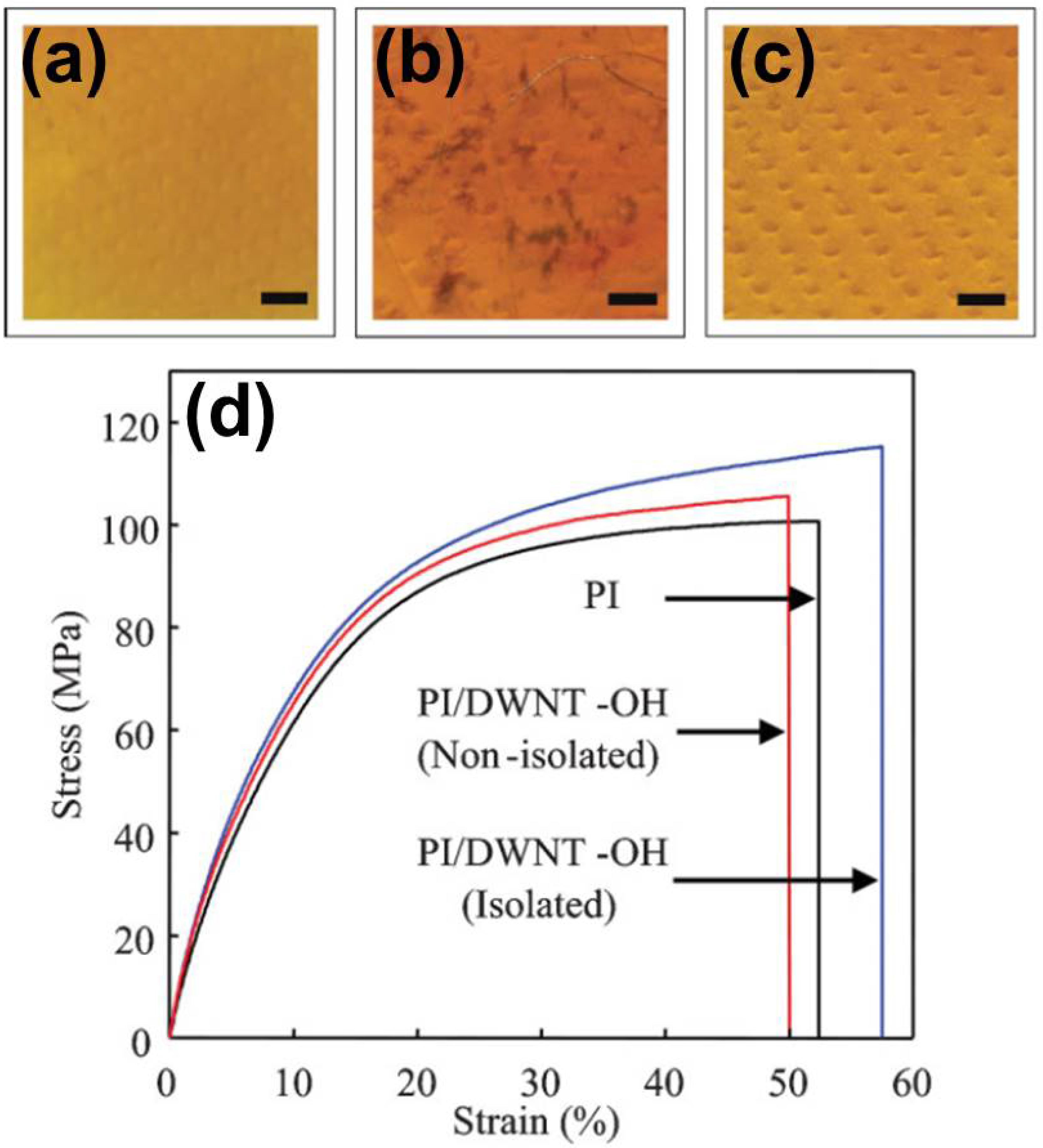
DWNTs and TWNTs were also shown to possess excellent mechanical properties, being more resistant than SWNTs to tensile loads and strains [173]. Recently, DWNTs were also shown to have good superlubricity properties, whereby the inner tubes can easily slide across the interior of the outer tube composing the system [174]. DWNTs can also be used to reinforce polyimide composites, which may be used in electronic devices, transparent conducting films and aerospace parts. Individually-dispersed DWNTs do not perturb transparency, while the non-isolated tubes are randomly aggregated and, thus, deteriorate the visual appearance of the polyimide film, as shown in Figure 12a–c. The chemically-modified and -isolated DWNTs lead to increased modulus, tensile strength and elongational break of polyimide nanocomposites [162], as shown in Figure 12d.
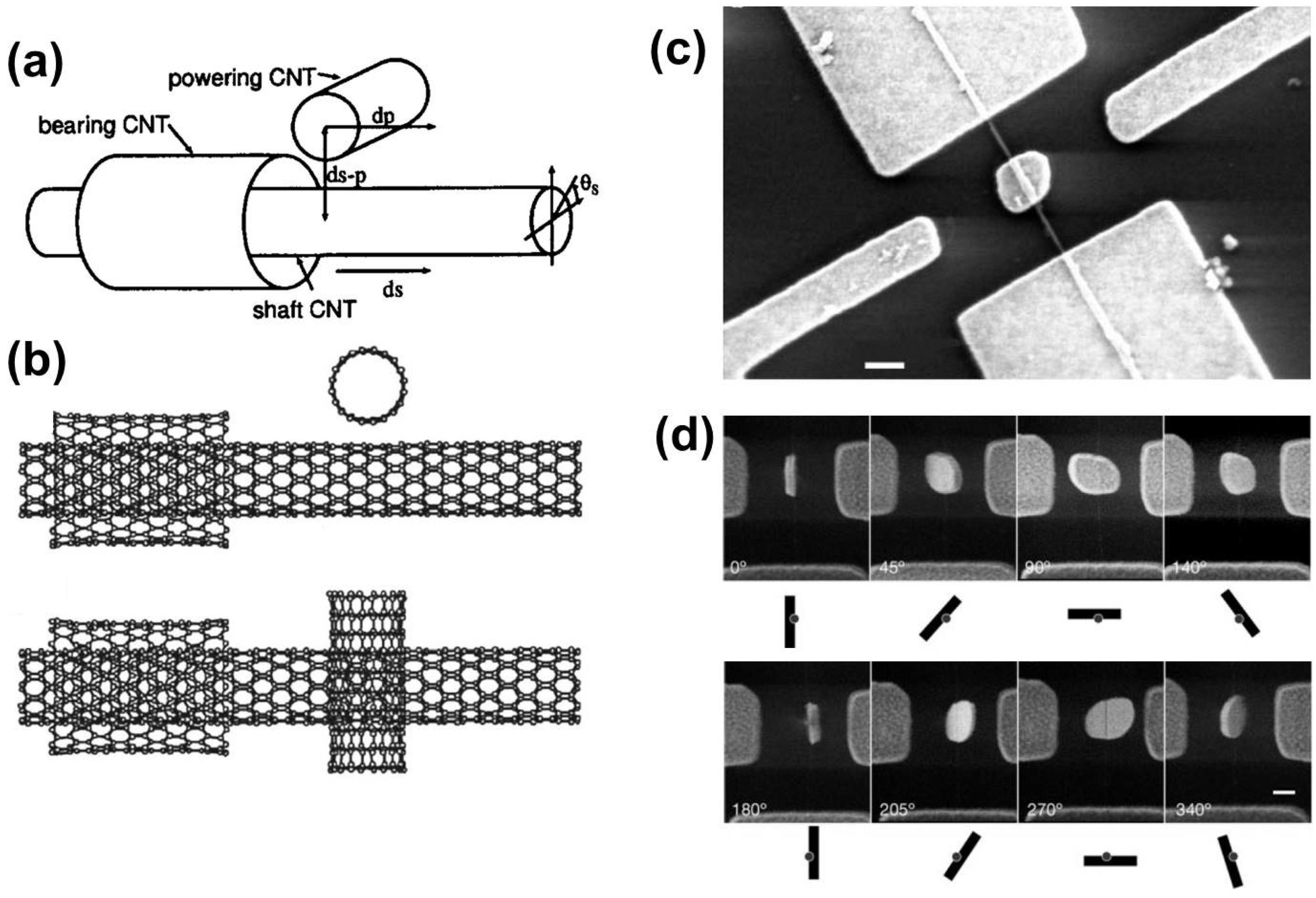
The weak IL interactions observed in DWNTs and TWNTs make them excellent candidates for the fabrication of nano-motors and nano-actuators [175,176,177,178]. Bourlon et al. [175] used multi-walled carbon nanotubes as bearings for rotating platforms, while Takagi et al. [176] proposed a nanomotor based on SWNTs and DWNTs in mechanical contact with each other. In their design, as shown in Figure 13a–c, the SWNT is used as a power nanotube, which can translate along the DWNTs axis, which is composed of one shaft nanotube (inner tube) and a bearing nanotube (outer tube). Their calculations suggested good controllability for translational and rotational motions in their nanomotor, and this controllability may be tuned according to SWNT species composing the DWNTs [176]. Fennimore et al. [177] also reported a fully functional design that would work either as a nanometer-scale electromechanical system or as a micro-electromechanical system. Figure 13c,d shows SEM images of the motor, which consists of a plate attached to the outer SWNT of the DWNT, and various angular positions of the plate [177].
There is plenty of room, as well, for the application of few-walled carbon nanotubes in devices for energy harvesting/storage (solar cells, for example) and sensors [179,180,181,182,183,184,185,186,187,188,189,190,191,192,193,194,195,196,197]. Indeed, we currently feel that finally the synthesis methods have advanced significantly to be technologically useful for producing high quality materials that are appropriate for testing several CNT applications that have been proposed in the literature or have been poorly tested. In 2010, Li and co-authors [182] demonstrated that DWNTs can serve as new channels for the establishment of an emerging class of delivery systems for the transport and translocation of DNA molecules and other types of biomolecules. Their method depends on the fact that DWNTs are more robust than SWNTs as regards voltage applications, and by following this line of reasoning, we suggest that TWNTs may provide another convenient option for the further development of such delivery systems.
In the field of solar cells, CNTs have been mostly used as base materials for transparent conductive films as an attempt to replace ITO (indium tin oxide) substrates, which are very expensive [183,184,185,186,187,188]. In some cases, the nanotube systems were not involved in the photo-generation process [183,184,185]. However, the nanotube structures can also be combined with silicon to produce heterojunction solar cells [186,187,188]. In these cases, the CNTs play an important role in the photo-generation process. Jia et al. [186] proposed a design in which the manufacturing process is simple and scalable, involving solution transfer of a porous, single-layer film of double-walled nanotubes to a silicon surface to form heterojunctions with silicon. The method does not require the separation of metallic and semiconducting nanotubes, and their solar cell devices achieved efficiencies of about 7% compared to the 10% usually observed in the commonly-used polymer-based cells. Wei et al. [187] also demonstrated that DWNTs could be potentially used for both photogeneration sites and charge carrier collecting/transport layer in DWNT-based solar cells. However, in this design, the efficiency, which lays around 1%, is not as good as the one obtained by the nanotube-silicon heterojunctions solar cells. In the same line, Shu et al. [188] designed and measured a hybrid photoelectrochemical cell (PEC) formed by a heterojunction made of a thin film of DWNTs and silicon nanowires, as show in Figure 14. In their design, the DWNTs also serve as the transparent counter electrode of the PEC cell. Again, the efficiency obtained by their solar cell device was lower than 1.3% (see Figure 14b). Although DWNTs can be used for photogeneration and electrodes simultaneously, the efficiencies obtained from devices are still farfrom reaching those observed in polymer-based cells.
As base materials for sensors, these multi-walled carbon nanotube (MWNT) systems are promising in a variety of ways: mass sensors, bio-sensors, strain sensors, temperature sensors and more [189,190,191,192,193,194,195,196,197]. As an example, p-aminophenol-modified multi-walled carbon nanotubes have been successfully tested as a sensor to detect vitamin C (ascorbic acid) via its electrochemical oxidation [197]. Furthermore, MWNTs/Pd-Ir composites have also been effectively utilized as supramolecular imprinted sensors capable of detecting carbofuran [194], and electrochemical sensors for detecting chloramphenicol based on multi-walled tubes were designed and successfully tested, as well [189]. Sensors for controlling and monitoring of human motions were also recently designed [190]. It is also important to comment that the surfaces of the CNTs constituting a MWNT system, as well as the interstitial site present in bundled samples will change with increasing the number of layers in the MWNT system. As an example, the use of DWNTs with appropriate diameter distributions has been used for H 2 adsorption [198]. The DWNT systems exhibited a H 2 adsorption two-times higher than the adsorption observed in SWNT systems [198]. In fact, as the number of walls increases, the molecular potential observed at the constituent carbon nanotube surfaces increases, but on the other hand, the pore size, the pore volume and the surface area decrease. Therefore, there should be an ideal number of walls and diameters in MWNT systems, so that different molecules can be more efficiently adsorbed. These are just a few examples of how industry can take advantage of the electrical, vibrational and mechanical properties of the multi-walled carbon nanotubes, which include DWNTs and TWNTs.

6. Conclusions and Future Perspectives

The development of powerful methods for growing CNTs has reached the state-of-the-art for SWNT growth, and the expectation is that the growth techniques will eventually reach such a state for the growth of few-walled carbon nanotubes (such as DWNTs and TWNTs), as well. The main parameters in the catalytic growth of DWNTs and TWNTs are: (1) the size and shape of metal particles or the thickness of metal films; (2) the use of promoters (Mo and S); and (3) reaction conditions (e.g., temperature, pressure and gas flow rate). Basically, the dimensions of the catalyst particles determine the number of walls in the carbon nanotube structure resultant from the growth process. It is worth mentioning that the metal catalyst acts like a reservoir for carbon atoms. The concentration of Mo or S in the catalyst particles/films plays an important role in determining both the size of catalyst particles and the deposition rate of carbon atoms during the carbon nanotube growth time. Indeed, the decomposition rate of hydrocarbons on the catalysts surface, as well as the carbon diffusion (segregation) into (out of) the catalyst particles/films both change the number of walls in the process of synthesizing the carbon nanotube structures. For example, the increase in the number of walls constituting the CNTs in the growth process was observed with increasing the concentration of Mo in the catalyst medium. The growth of TWNTs is considerably harder when compared to the growth of DWNTs. In fact, the reaction window for the selective growth of TWNTs is much narrower than that for DWNTs, and any small variation in the growth conditions is already enough to jeopardize the synthesis of TWNTs.
As discussed throughout the text, the growth techniques are already able to achieve high selectivity (>80%) for DWNTs and TWNTs species relative to other carbon structures produced simultaneously in the growth procedure. The control of DWNT and TWNT diameters is also in an advanced stage, although there is still a way to go as it comes to the chirality-specific growth of such systems. However, as mentioned above, the synthesis of DWNTs and TWNTs did reach a stage in which more sophisticated science can now be carried out, not only in terms of applications, but also in terms of fundamental science related to electrons, phonons, electron-electron interactions, electron-phonon interactions and phonon-phonon interactions (also known as many-body interactions), which are well understood in monolayer graphene and its multi-layer counterparts [199,200,201,202,203]. Both DWNTs and TWNTs, which are concentric SWNTs, have interesting phenomena related to their IL interactions [202,203,204,205]. These IL interactions are mediated by van der Waals forces, and they change as the chirality of the tubes composing the DWNTs and TWNTs changes, which therefore modifies how strongly the electronic and vibrational structures of each SWNT constituent will mix together in DWNT and TWNT systems. In fact, these IL interactions when well understood can be used in device applications, which work in the infrared regime [202,203,204,205].
The chirality and metallicity of the DWNTs and TWNTs constituents are certainly important to understand in depth the electronic and thermal properties, as well, and a good understanding of such properties is still elusive for few-walled carbon nanotubes. Regarding the use of DWNTs and TWNTs in biological applications, there still remains much to understand about their toxicity in living organisms and also their role as potential drug-delivery agents [182]. The mechanical robustness and the variety of metallicities observed in DWNTs and TWNTs could also be explored, for example to enhance the quality and resolution of scanning probe microscopy (SPM) probes [206,207]. Moreover, as we reported in Section 5, even though there are some applications that have already been tested using DWNTs and TWNTs, there are also various predictions still awaiting confirmation. In general, the authors understand that the effective use of DWNTs and TWNTs in nanotechnology is still under development and might experience a boost in the next few years provided that better samples can be produced. Finally, the authors believe that these recent advances in DWNT and TWNT synthesis are giving a new perspective to carbon nanotube science, which now has the potential to inaugurate a new era in this more than 25-year-old research field.

Acknowledgments

Yoong Ahm Kim acknowledges the financial support from the National Research Foundation of Korea (NRF) grant funded by the Korean government (MSIP) (No. NRF-2014R1A2A1A10050585) and from the framework of the international cooperation program managed by the National Research Foundation of Korea (NRF-2015K2A2A4000110, FY2015). Mildred S. Dresselhaus acknowledges support from the U.S. National Science Foundation NSF-DMR-1507806. Paulo T. Araujo acknowledges the University of Alabama College of Arts and Sciences for the financial support provided through the startup funds.

Author Contributions

All of the authors equally participated in the discussions and in the writing of the manuscript.

Conflicts of Interest

The authors declare no conflict of interest.

References

  1. Iijima, S. Helical microtubules of graphitic carbon. Nature 1991, 354, 56–58. [Google Scholar] [CrossRef]
  2. Saito, R.; Hofmann, M.; Dresselhaus, G.; Jorio, A.; Dresselhaus, M.S. Raman spectroscopy of graphene and carbon nanotubes. Adv. Phys. 2011, 60, 413–550. [Google Scholar] [CrossRef]
  3. Dresselhaus, M.S.; Dresselhaus, G.; Saito, R.; Jorio, A. Raman spectroscopy of graphene and carbon nanotubes. Phys. Rep. 2005, 409, 47–99. [Google Scholar] [CrossRef]
  4. Barros, E.B.; Jorio, A.; Samsonidze, G.G.; Capaz, R.B.; Souza Filho, A.G.; Mendes Filho, J.; Dresselhaus, G.; Dresselhaus, M.S. Review on the symmetry-related properties of carbon nanotubes. Phys. Rep. 2006, 431, 261–302. [Google Scholar] [CrossRef]
  5. Castro Neto, A.H.; Guinea, F.; Peres, N.M.R.; Novoselov, K.S.; Geim, A.K. The electronic properties of graphene. Rev. Mod. Phys. 2009, 81, 109–162. [Google Scholar] [CrossRef]
  6. Kotov, V.N.; Uchoa, B.; Pereira, V.M.; Guinea, F.; Castro Neto, A.H. Electron-electron interactions in graphene: Current status and perspectives. Rev. Mod. Phys. 2012, 84, 1067–1125. [Google Scholar] [CrossRef]
  7. Araujo, P.T.; Pesce, P.B.C.; Dresselhaus, M.S.; Sato, K.; Saito, R.; Jorio, A. Resonance Raman spectroscopy of the radial breathing modes in carbon nanotubes. Physica E 2010, 42, 1251–1261. [Google Scholar] [CrossRef]
  8. Pimenta, M.A.; Gomes, A.P.; Fantini, C.; Cancado, L.G.; Araujo, P.T.; Maciel, I.O.; Santos, A.P.; Furtado, C.A.; Peressinoto, V.S.T.; Plentz, F.; et al. Optical studies of carbon nanotubes and nanographites. Physica E 2007, 42, 88–92. [Google Scholar] [CrossRef]
  9. Mafra, D.L.; Araujo, P.T. Intra- and Interlayer Electron-Phonon Interactions in 12/12C and 12/13C BiLayer Graphene. Appl. Sci. 2014, 4, 207–239. [Google Scholar] [CrossRef]
  10. Saito, R.; Sato, K.; Araujo, P.T.; Mafra, D.L.; Dresselhaus, M.S. Gate modulated Raman spectroscopy of graphene and carbon nanotubes. Solid State Commun. 2013, 175, 18–34. [Google Scholar] [CrossRef]
  11. Kim, P.; Odom, T.W.; Huang, J.-L.; Lieber, C.M. Electronic density of states of atomically resolved single-walled carbon nanotubes: Van hove singularities and end states. Phys. Rev. Lett. 1999, 82, 1225–1228. [Google Scholar] [CrossRef]
  12. Misewich, J.A.; Martel, R.; Avouris, P.; Tsang, J.C.; Heinze, S.; Tersoff, J. Electrically induced optical emission from a carbon nanotube FET. Science 2003, 300, 783–786. [Google Scholar] [CrossRef] [PubMed]
  13. Baughman, R.B.; Zakhidov, A.A.; de Heer, W.A. Carbon nanotubes—The route toward applications. Science 2002, 297, 787–792. [Google Scholar] [CrossRef] [PubMed]
  14. Bahena-Garrido, S.; Shimoi, N.; Abe, D.; Hojo, T.; Tanaka, Y.; Tohji, K. Plannar light source using a phosphor screen with single-walled carbon nanotubes as field emitters. Rev. Sci. Instrum. 2014, 85. [Google Scholar] [CrossRef] [PubMed]
  15. Gabor, N.M.; Zhong, Z.; Bosnick, K.; Park, J.; McEuen, P.L. Extremely efficient multiple electron-hole pair generation in carbon nanotube photodiodes. Science 2009, 325, 1367–1371. [Google Scholar] [CrossRef] [PubMed]
  16. Gabor, N.M.; Zhong, Z.; Bosnick, K.; McEuen, P.L. Ultrafast photocurrent measurement of the escape time of electrons and holes from carbon nanotube p-i-n photodiodes. Phys. Rev. Lett. 2012, 108. [Google Scholar] [CrossRef] [PubMed]
  17. Kymakis, E.; Amaratunga, G.A.J. Single-wall carbon nanotube/conjugated polymer photovoltaic devices. Appl. Phys. Lett. 2002, 80, 112–114. [Google Scholar] [CrossRef]
  18. Ago, H.; Petritsch, K.; Shaffer, M.S.P.; Windle, A.H.; Friend, R.H. Composites of carbon nanotubes and conjugated polymers for photovoltaic devices. Adv. Mater. 1999, 11, 1281–1285. [Google Scholar] [CrossRef]
  19. Zhang, D.; Koungmin, R.; Liu, X.; Polikarpov, E.; Ly, J.; Tompson, M.E.; Zhou, C. Transparent, conductive, and flexible carbon nanotube films and their application in organic light-emitting diodes. Nano Lett. 2006, 6, 1880–1886. [Google Scholar] [CrossRef] [PubMed]
  20. Li, J.; Hu, L.; Wang, L.; Zhou, Y.; Grüner, G.; Marks, T.J. Organic light-emitting diodes having carbon nanotube anodes. Nano Lett. 2006, 11, 2472–2477. [Google Scholar] [CrossRef] [PubMed]
  21. Kim, Y.A.; Yang, K.S.; Muramatsu, H.; Hayashi, T.; Endo, M.; Terrones, M.; Dresselhaus, M.S. Double-wall carbon nanotubes: Synthesis, structural characterization, and application. Carbon Lett. 2014, 15, 77–88. [Google Scholar] [CrossRef]
  22. Kasperski, A.; Weibel, A.; Datas, L.; Grave, E.D.; Peigney, A.; Laurent, C. Large-diameter single-wall carbon nanotubes formed alongside small-diameter double-walled carbon nanotubes. J. Phys. Chem. C 2015, 119, 1524–1535. [Google Scholar] [CrossRef]
  23. Zhao, J.; Su, Y.; Yang, Z.; Wei, L.; Wang, Y.; Zhang, Y. Arc synthesis of double-walled carbon nanotubes in low pressure air and their superior field emission properties. Carbon 2013, 58, 92–98. [Google Scholar] [CrossRef]
  24. Su, Y.; Zhou, P.; Zhao, J.; Yang, Z.; Zhang, Y. Large-scale synthesis of few-walled carbon nanotubes by DC arc discharge in low-pressure flowing air. Mater. Res. Bull. 2013, 48, 3232–3235. [Google Scholar] [CrossRef]
  25. Taki, Y.; Shinohara, K.; Kikuchi, M.; Tanaka, A. Selective growth of vertically aligned single-, double-, and triple-walled carbon nanotubes by radiation-heated chemical vapor deposition. Jpn. J. Appl. Phys. 2008, 47, 721–724. [Google Scholar] [CrossRef]
  26. Kim, Y.A.; Muramatsu, H.; Hayashi, T.; Endo, M.; Terrones, M.; Dresselhaus, M.S. Thermal stability and structural changes of double-walled carbon nanotubes by heat treatment. Chem. Phys. Lett. 2004, 398, 87–92. [Google Scholar] [CrossRef]
  27. Qiu, H.; Shi, Z.; Gu, Z.; Qiu, J. Controllable preparation of triple-walled carbon nanotubes and their growth mechanism. Chem. Commun. 2007, 23, 1092–1094. [Google Scholar] [CrossRef] [PubMed]
  28. Shi, W.; Wang, Z.; Zhang, Q.; Zheng, Y.; Ieong, C.; He, M.; Lortz, R.; Cai, Y.; Wang, N.; Zhang, T.; et al. Superconductivity in bundles of double-wall carbon nanotubes. Sci. Rep. 2012, 2. [Google Scholar] [CrossRef] [PubMed]
  29. Muramatsu, H.; Hayashi, T.; Kim, Y.A.; Shimamoto, D.; Endo, M.; Meunier, V.; Sumpter, B.G.; Terrones, M.; Dresselhaus, M.S. Bright photoluminescence from the inner tubes of peapod-derived double walled carbon nanotubes. Small 2009, 5, 2678–2682. [Google Scholar] [CrossRef] [PubMed]
  30. Charlier, J.-C.; Blase, X.; Roche, S. Electronic and transport properties of nanotubes. Rev. Mod. Phys. 2007, 79, 677–732. [Google Scholar] [CrossRef]
  31. Ho, Y.H.; Chang, C.P.; Shyu, F.L.; Chen, R.B.; Chen, S.C.; Lin, M.F. Electronic and optical properties of double-walled armchair carbon nanotubes. Carbon 2004, 42, 3159–3167. [Google Scholar] [CrossRef]
  32. Lambin, Ph.; Meunier, V.; Rubio, A. Electronic structure of polychiral carbon nanotubes. Phys. Rev. B 2000, 62, 5129–5135. [Google Scholar] [CrossRef]
  33. Wei, J.; Zhu, H.; Jiang, B.; Ci, L.; Dehai, W.E. Electronic properties of double-walled carbon nanotube films. Carbon 2003, 41, 2495–2500. [Google Scholar] [CrossRef]
  34. Tison, Y.; Giusca, C.E.; Stolojan, V.; Hayashi, Y.; Silva, R.P. The inner shell influence on the electronic structure of double-walled carbon nanotubes. Adv. Mater. 2008, 20, 189–194. [Google Scholar] [CrossRef]
  35. Soto, M.; Boyer, T.A.; Biradar, S.; Ge, L.; Vajtai, R.; Elías-Zúñiga, A.; Ajayan, P.M.; Barrera, E.V. Effect of interwall interaction on the electronic structure of double-walled carbon nanotubes. Nanotechnology 2015, 26. [Google Scholar] [CrossRef] [PubMed]
  36. Saito, R.; Dresselhaus, G.; Dresselhaus, M.S. Electronic structure of double-layer graphene tubules. J. Appl. Phys. 1993, 73, 494–500. [Google Scholar] [CrossRef]
  37. Charlier, J.-C.; Michenaud, J.-P. Energetics of multilayered carbon tubules. Phys. Rev. Lett. 1993, 70, 1858–1861. [Google Scholar] [CrossRef] [PubMed]
  38. Saito, R.; Matsuo, R.; Kimura, T.; Dresselhaus, G.; Dresselhaus, M.S. Anomalous potential barrier of double-wall carbon nanotubes. Chem. Phys. Lett. 2001, 348, 187–193. [Google Scholar] [CrossRef]
  39. Park, H.J.; Oh, K.A.; Park, M.; Lee, H. Electrical properties and conductivity mapping of thin multilayered films containing different types of carbon nanotubes. J. Phys. Chem. C 2009, 113, 13070–13076. [Google Scholar] [CrossRef]
  40. Moon, S.; Song, W.; Lee, J.S.; Kim, N.; Kim, J.; Lee, S.-G.; Choi, M.-S. Eightfold shell filling in a double-wall carbon nanotube quantum dot. Phys. Rev. Lett. 2007, 99, 176804–176808. [Google Scholar] [CrossRef] [PubMed]
  41. Langer, L.; Bayot, V.; Grivei, E.; Issi, J.-P.; Heremans, J.P.; Olk, C.H.; Stockman, L.; van Haesendonck, C.; Bruynseraede, Y. Quantum transport in a multiwalled carbon nanotube. Phys. Rev. Lett. 1996, 76, 479–483. [Google Scholar] [CrossRef] [PubMed]
  42. Martel, R.; Schmidt, T.; Shea, H.R.; Hertel, T.; Avouris, Ph. Single- and multi-wall carbon nanotube field-effect transistors. Appl. Phys. Lett. 1998, 73, 2447–2450. [Google Scholar] [CrossRef]
  43. Kim, P.; Shi, L.; Majumdar, A.; McEuen, P.L. Thermal Transport Measurements of Individual Multiwalled Nanotubes. Phys. Rev. Lett. 2001, 87, 215502–215506. [Google Scholar] [CrossRef] [PubMed]
  44. Li, H.J.; Lu, W.G.; Li, J.J.; Bai, X.D.; Gu, C.Z. Multichannel ballistic transport in multiwall carbon nanotubes. Phys. Rev. Lett. 2005, 95, 086601–086605. [Google Scholar] [CrossRef] [PubMed]
  45. Kwon, Y.-K.; Tomanek, D. Electronic and structural properties of multiwall carbon nanotubes. Phys. Rev. B 1998, 58. [Google Scholar] [CrossRef]
  46. Purcell, S.T.; Vincent, P.; Journet, C.; Binh, V.T. Hot nanotubes: Stable heating of individual multiwall carbon nanotubes to 2000 K induced by the field-emission current. Phys. Rev. Lett. 2002, 88, 105502–105506. [Google Scholar] [CrossRef] [PubMed]
  47. Cumings, J.; Zettl, A. Low-friction nanoscale linear bearing realized from multiwall carbon nanotubes. Science 2000, 289, 602–604. [Google Scholar] [CrossRef] [PubMed]
  48. Xia, Z.H.; Guduru, P.R.; Curtin, W.A. Enhancing mechanical properties of multiwall carbon nanotubes via sp3 interwall bridging. Phys. Rev. Lett. 2007, 98, 245501–245506. [Google Scholar] [CrossRef] [PubMed]
  49. Son, Y.-W.; Oh, S.; Ihm, J.; Han, S. Field emission properties of double-wall carbon nanotubes. Nanotechnology 2004, 16. [Google Scholar] [CrossRef]
  50. Shimada, T.; Sugai, T.; Ohno, Y.; Kishimoto, S.; Mizutani, T.; Yoshida, H.; Okazaki, T.; Shinohara, H. Double-wall carbon nanotube field-effect transistors: Ambipolar transport characteristics. Appl. Phys. Lett. 2004, 84, 2412–2415. [Google Scholar] [CrossRef]
  51. Pantano, A.; Parks, D.M.; Boyce, M.C. Mechanics of deformation of single- and multi-wall carbon nanotubes. J. Mech. Phys. Solids 2004, 52, 789–821. [Google Scholar] [CrossRef]
  52. Liu, T.; Phang, I.Y.; Shen, L.; Chow, S.Y.; Zhang, W.-D. Morphology and mechanical properties of multiwalled carbon nanotubes reinforced nylon-6 composites. Macromolecules 2004, 37, 7214–7222. [Google Scholar] [CrossRef]
  53. Pumera, M. Electrochemical properties of double wall carbon nanotube electrodes. Nanoscale Res. Lett. 2007, 2, 87–93. [Google Scholar] [CrossRef]
  54. Koshino, M.; Moon, P.; Som, Y.-W. Incommensurate double-walled carbon nanotubes as one-dimensional moiré crystals. Phys. Rev. B 2015, 91. [Google Scholar] [CrossRef]
  55. Liu, K.; Jin, C.; Hong, X.; Kim, J.; Zettl, A.; Wang, E.; Wang, F. Van der Waals-coupled electronic states in incommensurate double-walled carbon nanotubes. Nat. Phys. 2014, 10, 737–742. [Google Scholar] [CrossRef]
  56. Liu, K.; Hong, X.; Wu, M.; Xiao, F.; Wang, W.; Bai, X.; Ager, J.W.; Aloni, S.; Zettl, A.; Wang, E.; et al. Quantum-coupled radial-breathing oscillations in double-walled carbon nanotubes. Nat. Commun. 2012, 4. [Google Scholar] [CrossRef] [PubMed]
  57. Hirschmann, T.C.; Dresselhaus, M.S.; Muramatsu, H.; Seifert, M.; Wurstbauer, U.; Parzinger, E.; Nielsch, K.; Kim, Y.A.; Araujo, P.T. G band in double-and triple-walled carbon nanotubes: A Raman study. Phys. Rev. B 2015, 91. [Google Scholar] [CrossRef]
  58. Hirschmann, T.C.; Araujo, P.T.; Muramatsu, H.; Rodriguez-Nieva, J.F.; Seifert, M.; Nielsch, K.; Kim, Y.A.; Dresselhaus, M.S. Role of intertube interactions in double-and triple-walled carbon nanotubes. ACS Nano 2014, 8, 1330–1341. [Google Scholar] [CrossRef] [PubMed]
  59. Hirschmann, T.C.; Araujo, P.T.; Muramatsu, H.; Zhang, X.; Nielsch, K.; Kim, Y.A.; Dresselhaus, M.S. Characterization of bundled and individual triple-walled carbon nanotubes by resonant Raman spectroscopy. ACS Nano 2013, 7, 2381–2387. [Google Scholar] [CrossRef] [PubMed]
  60. Noffsinger, J.; Cohen, M.L. Electron-phonon coupling and superconductivity in double-walled carbon nanotubes. Phys. Rev. B 2011, 83. [Google Scholar] [CrossRef]
  61. Murata, N.; Haruyama, J.; Ueda, Y.; Matsudaira, M.; Karino, H.; Yagi, Y.; Einarsson, E.; Chiashi, S.; Maruyama, S.; Sugai, T.; et al. Meissner effect in honeycomb arrays of multiwalled carbon nanotubes. Phys. Rev. B 2007, 76. [Google Scholar] [CrossRef]
  62. Takesue, I.; Haruyama, J.; Kobayashi, N.; Chiashi, S.; Maruyama, S.; Sugai, T.; Shinohara, H. Superconductivity in entirely end-bonded multiwalled carbon nanotubes. Phys. Rev. Lett. 2006, 96. [Google Scholar] [CrossRef] [PubMed]
  63. Barzola-Quiquia, J.; Esquinazi, P.; Lindel, M.; Spemann, D.; Muallem, M.; Nessim, G.D. Magnetic order and superconductivity observed in bundles of double-wall carbon nanotubes. Carbon 2015, 88, 16–25. [Google Scholar] [CrossRef]
  64. Latgé, A.; Grimm, D.; Ferreira, M.S. Magnetic field effects of double-walled carbon nanotubes. Braz. J. Phys. 2006, 36, 898–901. [Google Scholar]
  65. Postupna, O.; Long, R.; Prezhdo, O.V. Time-domain Ab initio simulation of energy transfer in double-walled carbon nanotubes. J. Phys. Chem. C 2015, 119, 12088–12094. [Google Scholar] [CrossRef]
  66. Bacsa, R.R.; Laurent, Ch.; Peigney, A.; Puech, P.; Hubel, H.; Dunstan, D.; Bacsa, W.S. Structural and mechanical properties of double wall carbon nanotubes. NSTI-Nanotech 2004 2004, 3, 214–217. [Google Scholar]
  67. Natsuki, T.; Hayashi, T.; Endo, M. Mechanical properties of single and double-walled carbon nanotubes under hydrostatic pressure. Appl. Phys. A 2006, 83, 13–17. [Google Scholar] [CrossRef]
  68. Huang, J.Y.; Chen, S.; Ren, Z.F.; Wang, Z.; Kmpa, K.; Naughton, M.J.; Chen, G.; Dresselhaus, M.S. Enhanced ductile behavior of tensile-elongated individual double-walled and triple-walled carbon nanotubes at high temperatures. Phys. Rev. Lett. 2007, 98. [Google Scholar] [CrossRef] [PubMed]
  69. Motta, M.; Moisala, A.; Kinloch, I.A.; Windle, A.H. High performance fibres from ‘dog bone’ carbon nanotubes. Adv. Mater. 2007, 19, 3721–3726. [Google Scholar] [CrossRef]
  70. Li, Y.-L.; Kinloch, I.A.; Windle, A.H. Direct spinning of carbon nanotube fibers from chemical vapor deposition synthesis. Science 2004, 304, 276–278. [Google Scholar] [CrossRef] [PubMed]
  71. Cui, S.; Kinloch, I.A.; Young, R.J.; Noé, L.; Monthioux, M. The Effect of stress transfer within double-walled carbon nanotubes upon their ability to reinforce composites. Adv. Mater. 2009, 21, 3591–3595. [Google Scholar] [CrossRef]
  72. Alencar, R.S.; Aguiar, A.L.; Paschoal, A.R.; Freire, P.T.C.; Kim, Y.A.; Muramatsu, H.; Endo, M.; Terrones, H.; Terrones, M.; San-Miguel, A.; et al. Pressure-induced selectivity for probing inner tubes in double- and triple-walled carbon nanotubes: A resonance raman study. J. Phys. Chem. C 2014, 118, 8153–8158. [Google Scholar] [CrossRef]
  73. Liu, Q.; Ren, W.; Li, F.; Cong, H.; Cheng, H.M.J. Synthesis and high thermal stability of double-wall carbon nanotubes using nickel formate dihydrate as catalyst precursor. Phys. Chem. C 2007, 111, 5006–5013. [Google Scholar] [CrossRef]
  74. Huang, H.; Kajiura, H.; Tsutsui, S.; Murakami, Y.; Ata, M. High-quality double-walled carbon nanotube super bundles grown in a hydrogen-free atmosphere. J. Phys. Chem. B 2003, 107, 8794–8798. [Google Scholar] [CrossRef]
  75. Chen, Z.-G.; Li, F.; Ren, W.-C.; Cong, H.; Liu, C.; Lu, G.Q.; Cheng, H.-M. Double-walled carbon nanotubes synthesized using carbon black as the dot carbon source. Nanotechnology 2006, 17, 3100–3104. [Google Scholar] [CrossRef]
  76. Li, L.; Li, F.; Liu, C.; Cheng, H.-M. Synthesis and characterization of double-walled carbon nanotubes from multi-walled carbon nanotubes by hydrogen-arc discharge. Carbon 2005, 43, 623–629. [Google Scholar] [CrossRef]
  77. Qiu, J.; Chen, G.; Li, Z.; Zhao, Z. Preparation of double-walled carbon nanotubes from fullerene waste soot by arc-discharge. Carbon 2010, 48, 1312–1315. [Google Scholar] [CrossRef]
  78. Motta, M.; Moisala, A.; Kinloch, I.A.; Windle, A.H. The role of sulphur in the synthesis of carbon nanotubes by chemical vapour deposition at high temperatures. J. Nanosci. Nanotechnol. 2008, 8, 2442–2449. [Google Scholar] [CrossRef] [PubMed]
  79. Tibbetts, G.G.; Bernardo, C.A.; Gorkiewicz, D.W.; Alig, R.L. Role of sulfur in the production of carbon fibers in the vapor phase. Carbon 1994, 32, 569–576. [Google Scholar] [CrossRef]
  80. Hutchison, J.L.; Kiselev, N.A.; Krinichnaya, E.P.; Krestinin, A.V.; Loutfy, R.O.; Morawsky, A.P.; Muradyan, V.E.; Obraztsova, E.D.; Sloan, J.; Terekhov, S.V.; et al. Double-walled carbon nanotubes fabricated by a hydrogen arc discharge method. Carbon 2001, 39, 761–770. [Google Scholar] [CrossRef]
  81. Saito, Y.; Nakahira, T.; Uemura, S.J. Growth conditions of double-walled carbon nanotubes in arc discharge. Phys. Chem. B 2003, 107, 931–934. [Google Scholar] [CrossRef]
  82. Qiu, H.; Shi, Z.; Guan, L.; You, L.; Gao, M.; Zhang, S.; Qiu, J.; Gu, Z. High-efficient synthesis of double-wall carbon nanotubes by arc discharge method using chloride as a promoter. Carbon 2006, 44, 516–521. [Google Scholar] [CrossRef]
  83. Wang, S.-D.; Chang, M.-H.; Lan, K.M.-D.; Wu, C.-C.; Cheng, J.-J.; Chang, H.-K. Synthesis of carbon nanotubes by arc discharge in sodium chloride solution. Carbon 2005, 43, 1778–1814. [Google Scholar] [CrossRef]
  84. Liu, B.C.; Yu, B.; Zhang, M.X. Catalytic CVD synthesis of double-walled carbon nanotubes with a narrow distribution of diameters over Fe–Co/MgO catalyst. Chem. Phys. Lett. 2005, 407, 232–235. [Google Scholar] [CrossRef]
  85. Zhang, Q.; Qian, W.; Wen, Q.; Liu, Y.; Wang, D.; Wei, F. The effect of phase separation in Fe/Mg/Al/O catalysts on the synthesis of DWCNTs from methane. Carbon 2007, 45, 1645–1650. [Google Scholar] [CrossRef]
  86. Li, W.Z.; Wen, J.G.; Sennett, M.; Ren, Z.F. Clean double-walled carbon nanotubes synthesized by CVD. Chem. Phys. Lett. 2003, 368, 299–306. [Google Scholar] [CrossRef]
  87. Zhang, Y.-X.; Jia, Y. Synthesis of high-quality double-walled carbon nanotubes using porous MgO nanowire supported iron oxide as catalyst. Mater. Lett. 2013, 107, 46–49. [Google Scholar] [CrossRef]
  88. Ning, G.; Wei, F.; Wen, Q.; Luo, G.; Wang, Y.; Jin, Y. Improvement of Fe/MgO catalysts by calcination for the growth of single-and double-walled carbon nanotubes. Phys. Chem. B 2006, 110, 1201–1205. [Google Scholar] [CrossRef] [PubMed]
  89. Coquay, P.; Peigney, A.; de Grave, E.; Flahaut, E.; Vandenberghe, R.E.; Laurent, C.J. Fe/Co alloys for the catalytic chemical vapor deposition synthesis of single- and double-walled carbon nanotubes (CNTs). 1. the CNT-Fe/Co-MgO system. Phys. Chem. B 2005, 109, 17813–17824. [Google Scholar] [CrossRef] [PubMed]
  90. Flahaut, E.; Peigney, A.; Laurent, C.; Rousset, A. Synthesis of single-walled carbon nanotube–Co–MgO composite powders and extraction of the nanotubes. J. Mater. Chem. 2000, 10, 249–252. [Google Scholar] [CrossRef]
  91. Zhu, J.; Yudasaka, M.; Iijima, S. A catalytic chemical vapor deposition synthesis of double-walled carbon nanotubes over metal catalysts supported on a mesoporous material. Chem. Phys. Lett. 2003, 380, 496–502. [Google Scholar] [CrossRef]
  92. Flahaut, E.; Bacsa, R.; Peigney, A.; Laurent, C. Gram-scale CCVD synthesis of double-walled carbon nanotubes. Chem. Commun. 2003, 1442–1443. [Google Scholar] [CrossRef] [Green Version]
  93. Cumings, J.; Mickelson, W.; Zettl, A. Simplified synthesis of double-wall carbon nanotubes. Solid State Commun. 2003, 126, 359–362. [Google Scholar] [CrossRef]
  94. Gruneis, A.; Rummeli, M.H.; Kramberger, C.; Barreiro, A.; Pichler, T.; Pfeiffer, R.; Kuzmany, H.; Gemming, T.; Buchner, B. High quality double wall carbon nanotubes with a defined diameter distribution by chemical vapor deposition from alcohol. Carbon 2006, 44, 3177–3182. [Google Scholar] [CrossRef]
  95. Ning, G.; Liu, Y.; Wei, F.; Wen, Q.; Luo, G.J. Porous and lamella-like Fe/MgO catalysts prepared under hydrothermal conditions for high-yield synthesis of double-walled carbon nanotubes. Phys. Chem. C 2007, 111, 1969–1975. [Google Scholar] [CrossRef]
  96. Flahaut, E.; Laurent, C.; Peigney, A. Catalytic CVD synthesis of double and triple-walled carbon nanotubes by the control of the catalyst preparation. Carbon 2005, 43, 375–383. [Google Scholar] [CrossRef] [Green Version]
  97. Ramesh, P.; Okazaki, T.; Sugai, T.; Kimura, J.; Kishi, N.; Sato, K.; Ozeki, Y.; Shinohara, H. Purification and characterization of double-wall carbon nanotubes synthesized by catalytic chemical vapor deposition on mesoporous silica. Chem. Phys. Lett. 2006, 418, 408–412. [Google Scholar] [CrossRef]
  98. Hiraoka, T.; Kawakubo, T.; Kimura, J.; Taniguchi, R.; Okamoto, A.; Okazaki, T.; Sugai, T.; Ozeki, Y.; Yoshikawa, M.; Shinohara, H. Selective synthesis of double-wall carbon nanotubes by CCVD of acetylene using zeolite supports. Chem. Phys. Lett. 2003, 382, 679–685. [Google Scholar] [CrossRef]
  99. Ramesh, P.; Okazaki, T.; Taniguchi, R.; Kimura, J.; Sugai, T.; Sato, K.; Ozeki, Y.; Shinohara, H. Selective chemical vapor deposition synthesis of double-wall carbon nanotubes on mesoporous silica. J. Phys. Chem. B 2005, 109, 1141–1147. [Google Scholar] [CrossRef] [PubMed]
  100. Ago, H.; Nakamura, K.; Imamura, S.; Tsuji, M. Growth of double-wall carbon nanotubes with diameter-controlled iron oxide nanoparticles supported on MgO. Chem. Phys. Lett. 2004, 391, 308–313. [Google Scholar] [CrossRef]
  101. Liu, Y.; Qian, W.Z.; Zhang, Q.; Ning, G.Q.; Luo, G.H.; Wang, Y.; Wang, D.Z.; Wei, F. Synthesis of high-quality, double-walled carbon nanotubes in a fluidized bed reactor. Chem. Eng. Technol. 2009, 32, 73–79. [Google Scholar] [CrossRef]
  102. Qi, H.; Qian, C.; Liu, J. Synthesis of uniform double-walled carbon nanotubes using iron disilicide as catalyst. Nano Lett. 2007, 7, 2417–2421. [Google Scholar] [CrossRef] [PubMed]
  103. Lyu, S.C.; Liu, B.C.; Lee, S.H.; Park, C.Y.; Kang, H.K.; Yang, C.-W.; Lee, C.J. Large-scale synthesis of high-quality double-walled carbon nanotubes by catalytic decomposition of n-hexane. J. Phys. Chem. B 2004, 108, 2192–2194. [Google Scholar] [CrossRef]
  104. Endo, M.; Muramatsu, H.; Takuya, H.; Kim, Y.A.; Terrones, M.; Dresselhaus, M.S. Nanotechnology: “Buckypaper” from coaxial nanotubes. Nature 2005, 433. [Google Scholar] [CrossRef] [PubMed]
  105. Biris, A.R.; Lupu, D.; Gruneis, A.; Ayala, P.; Rümmeli, M.H.; Pichler, T.; Li, Z.; Xu, Y.; Misan, I.; Dervishi, E.; et al. High-quality double-walled carbon nanotubes grown by a cold-walled radio frequency chemical vapor deposition process. Chem. Mater. 2008, 20, 3466–3472. [Google Scholar] [CrossRef]
  106. Matsumoto, K.; Murakami, T.; Isshiki, T.; Kisoda, K.; Harima, H. Synthesis and Raman study of double-walled carbon nanotubes. Diam. Relat. Mater. 2007, 16, 1188–1191. [Google Scholar] [CrossRef]
  107. Chakrabarti, S.; Gong, K.; Dai, L.J. Structural evaluation along the nanotube length for super-long vertically aligned double-walled carbon nanotube arrays. Phys. Chem. C 2008, 112, 8136–8139. [Google Scholar] [CrossRef]
  108. Lamura, G.; Andreone, A.; Yang, Y.; Barbara, P.; Vigolo, B.; Herold, C.; Mareche, J.F.; Lagrange, P.; Cazayous, M.; Sacuto, A.; et al. High-crystalline single-and double-walled carbon nanotube mats grown by chemical vapor deposition. J. Phys. Chem. C 2007, 111, 15154–15159. [Google Scholar] [CrossRef]
  109. Liu, T.-Y.; Zhang, L.-L.; Yu, W.-J.; Li, S.-S.; Hou, P.-X.; Cong, H.-T.; Liu, C.; Cheng, H.-M. Growth of double-walled carbon nanotubes from silicon oxide nanoparticles. Carbon 2013, 56, 167–172. [Google Scholar] [CrossRef]
  110. Gunjishima, I.; Inoue, T.; Yamamuro, S.; Sumiyama, K.; Okamoto, A. Synthesis of vertically aligned, double-walled carbon nanotubes from highly active Fe–V–O nanoparticles. Carbon 2007, 45, 1193–1199. [Google Scholar] [CrossRef]
  111. Fu, Y.; Chen, S.; Bielecki, J.; Matic, A.; Wang, T.; Ye, L.-L.; Liu, J. Selective growth of double-walled carbon nanotubes on gold films. Mater. Lett. 2012, 72, 78–80. [Google Scholar] [CrossRef]
  112. Hiramatsu, M.; Nagao, H.; Taniguchi, M.; Amano, H.; Ando, Y.; Hori, M. High-rate growth of films of dense, aligned double-walled carbon nanotubes using microwave plasma-enhanced chemical vapor deposition. Jpn. J. Appl. Phys. 2005, 44, L693–L695. [Google Scholar] [CrossRef]
  113. Kondo, D.; Sato, S.; Kawabata, A.; Awano, Y. Selective growth of vertically aligned double-and single-walled carbon nanotubes on a substrate at 590°C. Nanotechnology 2008, 19, 435601. [Google Scholar] [CrossRef] [PubMed]
  114. Baliyan, A.; Uchida, T.; Fukuda, T.; Nakajima, Y.; Hanajiri, T.; Maekawa, T. Synthesis of a forest of double/triple walled CNTs of uniform diameters by plasma enhanced CVD using monodisperse iron oxide nanoparticles. J. Mater. Chem. 2012, 22, 5277–5280. [Google Scholar] [CrossRef]
  115. Futaba, D.N.; Goto, J.; Yasuda, S.; Yamada, T.; Yumura, M.; Hata, K. A background level of oxygen-containing aromatics for synthetic control of carbon nanotube structure. J. Amer. Chem. Soc. 2009, 131, 15992–15993. [Google Scholar] [CrossRef] [PubMed]
  116. Yamada, T.; Namai, T.; Hata, K.; Futaba, D.N.; Mizuno, K.; Fan, J.; Yudasaka, M.; Yumura, M.; Iijima, S. Size-selective growth of double-walled carbon nanotube forests from engineered iron catalysts. Nat. Nanotechnol. 2006, 1, 131–136. [Google Scholar] [CrossRef] [PubMed]
  117. Ci, L.; Rao, Z.; Zhou, Z.; Tang, D.; Yan, X.; Liang, Y.; Liu, D.; Yuan, H.; Zhou, W.; Wang, G.; et al. Double wall carbon nanotubes promoted by sulfur in a floating iron catalyst CVD system. Chem. Phys. Lett. 2002, 359, 63–67. [Google Scholar] [CrossRef]
  118. Zhou, Z.; Ci, L.; Chen, X.; Tang, D.; Yan, X.; Liu, D.; Liang, Y.; Yuan, H.; Zhou, W.; Wang, G.; et al. Controllable growth of double wall carbon nanotubes in a floating catalytic system. Carbon 2003, 41, 337–342. [Google Scholar] [CrossRef]
  119. Wei, J.; Jiang, B.; Wu, D.; Wei, B. Large-scale synthesis of long double-walled carbon nanotubes. J. Phys. Chem. B 2004, 108, 8844–8847. [Google Scholar] [CrossRef]
  120. Wei, J.; Zhu, H.; Jia, Y.; Shu, Q.; Li, C.; Wang, K.; Wei, B.; Zhu, Y.; Wang, Z.; Luo, J.; et al. The effect of sulfur on the number of layers in a carbon nanotube. Carbon 2007, 45, 2152–2158. [Google Scholar] [CrossRef]
  121. Zhong, X.H.; Li, Y.L.; Liu, Y.K.; Qiao, X.H.; Feng, Y.; Liang, J.; Jin, J.; Zhu, L.; Hou, F.; Li, J.Y. Continuous multilayered carbon nanotube yarns. Adv. Mater. 2010, 22, 692–696. [Google Scholar] [CrossRef] [PubMed]
  122. Zhong, X.H.; Li, Y.L.; Feng, J.M.; Kang, Y.R.; Han, S.S. Fabrication of a multifunctional carbon nanotube “cotton” yarn by the direct chemical vapor deposition spinning process. Nanoscale 2012, 4, 5614–5618. [Google Scholar] [CrossRef] [PubMed]
  123. Feng, J.-M.; Wang, R.; Li, Y.-L.; Zhong, X.-H.; Cui, L.; Guo, Q.-J.; Hou, F. One-step fabrication of high quality double-walled carbon nanotube thin films by a chemical vapor deposition process. Carbon 2010, 48, 3817–3824. [Google Scholar] [CrossRef]
  124. Ren, W.; Cheng, H.M. Aligned double-walled carbon nanotube long ropes with a narrow diameter distribution. J. Phys. Chem. B 2005, 109, 7169–7173. [Google Scholar] [CrossRef] [PubMed]
  125. Ago, H.; Nakamura, K.; Uehara, N.; Tsuji, M. Roles of metal-support interaction in growth of single-and double-walled carbon nanotubes studied with diameter-controlled iron particles supported on MgO. J. Phys. Chem. B 2004, 108, 18908–18915. [Google Scholar] [CrossRef]
  126. Ago, H.; Uehara, N.; Yoshihara, N.; Tsuji, M.; Yumura, M.; Tomonaga, N.; Setoguchi, T. Gas analysis of the CVD process for high yield growth of carbon nanotubes over metal-supported catalysts. Carbon 2006, 44, 2912–2918. [Google Scholar] [CrossRef]
  127. Hata, K.; Futaba, D.N.; Mizuno, K.; Namai, T.; Yumura, M.; Iijima, S. Water-assisted highly efficient synthesis of impurity-free single-walled carbon nanotubes. Science 2004, 306, 1362–1364. [Google Scholar] [CrossRef] [PubMed]
  128. Yamada, T.; Maigne, A.; Yudasaka, M.; Mizuno, K.; Futaba, D.N.; Yumura, M.; Iijima, S.; Hata, K. Revealing the secret of water-assisted carbon nanotube synthesis by microscopic observation of the interaction of water on the catalysts. Nano Lett. 2008, 8, 4288–4292. [Google Scholar] [CrossRef] [PubMed]
  129. Li, Y.-L.; Kinloch, I.A.; Windle, A.H. Direct spinning of carbon nanotube fibers from chemical vapor deposition synthesis. Science 2004, 304, 276–278. [Google Scholar] [CrossRef] [PubMed]
  130. Smith, B.W.; Monthioux, M.; Luzzi, D.E. Encapsulated C60 in carbon nanotubes. Nature 1998, 396, 323–324. [Google Scholar] [CrossRef]
  131. Bandow, S.; Hiraoka, T.; Yumura, T.; Hirahara, K.; Shinohara, H.; Iijima, S. Raman scattering study on fullerene derived intermediates formed within single-wall carbon nanotube: From pea pod to double-wall carbon nanotube. Chem. Phys. Lett. 2004, 384, 320–325. [Google Scholar] [CrossRef]
  132. Bandow, S.; Takizawa, M.; Hirahara, K.; Yudasaka, M.; Iijima, S. Raman scattering study of double-wall carbon nanotubes derived from the chains of fullerenes in single-wall carbon nanotubes. Chem. Phys. Lett. 2001, 337, 48–54. [Google Scholar] [CrossRef]
  133. Hernandez, E.; Meunier, V.; Smith, B.W.; Rurali, R.; Terrones, H.; Buongiorno Nardelli, M.; Terrones, M.; Luzzi, D.E.; Charlier, J.C. Fullerene coalescence in nanopea pods: A path to novel tubular carbon. Nano Lett. 2003, 3, 1037–1042. [Google Scholar] [CrossRef]
  134. Kalbac, M.; Kavan, L.; Juha, L.; Civis, S.; Zukalova, M.; Bittner, M.; Kubat, P.; Vorlicek, V.; Dunsch, L. Transformation of fullerene pea pods to double-walled carbon nanotubes induced by UV radiation. Carbon 2005, 43, 1610–1616. [Google Scholar] [CrossRef]
  135. Botka, B.; Fustos, M.E.; Klupp, G.; Kocsis, D.; Szekely, E.; Utczas, M.; Simandi, B.; Botos, A.; Hackl, R.; Kamaras, K. Low-temperature encapsulation of coronene in carbon nanotubes. Phys. Status Solidi B 2012, 249, 2432–2435. [Google Scholar] [CrossRef]
  136. Pfeiffer, R.; Pichler, T.; Kim, Y.A.; Kuzmany, H. Double-wall carbon nanotubes. In Springer Series on Topics in Appl. Phys., vol. 111; Jorio, A., Dresselhaus, M.S., Dresselhaus, G., Eds.; Springer-Verlag: Berlin, Germany, 2008; pp. 495–530. [Google Scholar]
  137. Lim, H.E.; Miyata, Y.; Kitaura, R.; Nishimura, Y.; Nishimoto, Y.; Irle, S.; Warner, J.H.; Kataura, H.; Shinohara, H. Growth of carbon nanotubes via twisted graphene nanoribbons. Nat. Commun. 2013, 4. [Google Scholar] [CrossRef] [PubMed]
  138. Fujita, Y.; Bandow, S.; Iijima, S. Formation of small-diameter carbon nanotubes from PTCDA arranged inside the single-wall carbon nanotubes. Chem. Phys. Lett. 2005, 413, 410–414. [Google Scholar] [CrossRef]
  139. Shiozawa, H.; Pichler, T.; Gruneis, A.; Pfeiffer, R.; Kuzmany, H.; Liu, Z.; Suenaga, K.; Kataura, H. A catalytic reaction inside a single-walled carbon nanotube. Adv. Mater. 2008, 20, 1443–1449. [Google Scholar] [CrossRef]
  140. Shiozawa, H.; Pichler, T.; Pfeiffer, R.; Kuzmany, H.; Kataura, H. Ferrocene encapsulated in single-wall carbon nanotubes: A precursor to secondary tubes. Phys. Status Solidi B 2007, 244, 4102–4105. [Google Scholar] [CrossRef]
  141. Guan, L.; Shi, Z.; Li, M.; Gu, Z. Ferrocene-filled single-walled carbon nanotubes. Carbon 2005, 43, 2780–2785. [Google Scholar] [CrossRef]
  142. Chamberlain, T.W.; Champness, N.R.; Schroder, M.; Khlobystov, A.N. A piggyback ride for transition metals: Encapsulation of exohedral metallofullerenes in carbon nanotubes. Chem. Eur. J. 2011, 17, 668–674. [Google Scholar] [CrossRef] [PubMed]
  143. Shen, C.; Brozena, A.H.; Wang, Y. Double-walled carbon nanotubes: Challenges and opportunities. Nanoscale 2011, 3, 503–518. [Google Scholar] [CrossRef] [PubMed]
  144. Yu, H.; Zhang, Q.; Luo, G.; Wei, F. Rings of triple-walled carbon nanotube bundles. Appl. Phys. Lett. 2006, 89. [Google Scholar] [CrossRef]
  145. Wen, Q.; Qian, W.; Nie, J.; Cao, A.; Ning, G.; Wang, Y.; Hu, L.; Zhang, Q.; Huang, J.; Wei, F. 100 mm long, semiconducting triple-walled carbon nanotubes. Adv. Mater. 2010, 22, 1867–1871. [Google Scholar] [CrossRef] [PubMed]
  146. Chiang, W.-H.; Futaba, D.N.; Yumura, M.; Hata, K. Direct wall number control of carbon nanotube forests from engineered iron catalysts. J. Nanosci. Nanotechnol. 2013, 13, 2745–2751. [Google Scholar] [CrossRef] [PubMed]
  147. Baliyan, A.; Nakajima, Y.; Fukuda, T.; Uchida, T.; Hanajiri, T.; Maekawa, T. Synthesis of an ultradense forest of vertically aligned triple-walled carbon nanotubes of uniform diameter and length using hollow catalytic nanoparticles. J. Amer. Chem. Soc. 2014, 136, 1047–1053. [Google Scholar] [CrossRef] [PubMed]
  148. Taki, Y.; Shinohara, K.; Kikuchi, M.; Tanaka, A. Selective growth of single-, double-, and triple-walled carbon nanotubes through precise control of catalyst diameter by radiation-heated chemical vapor deposition. Jpn. J. Appl. Phys. 2008, 47, 725–729. [Google Scholar] [CrossRef]
  149. Muramatsu, H.; Shimamoto, D.; Hayashi, T.; Kim, Y.A.; Terrones, M.; Endo, M.; Dresselhaus, M.S. Bulk synthesis of narrow diameter and highly crystalline triple-walled carbon nanotubes by coalescing fullerene pea pods. Adv. Mater. 2011, 23, 1761–1764. [Google Scholar] [CrossRef] [PubMed]
  150. Muramatsu, H.; Hayashi, T.; Fujisawa, K.; Tojo, T.; Ko, Y.-I.; Morelos-Gomez, A.; Yang, K.-S.; Kim, Y.A.; Endo, M.; Terrones, M.; et al. Boron-assisted coalescence of parallel multi-walled carbon nanotubes. RSC Advances 2013, 3, 26266–26270. [Google Scholar] [CrossRef]
  151. Araujo, P.T.; Jorio, A. The role of environmental effects on the optical transition energies and radial breathing mode frequency of single wall carbon nanotubes. Phys. Status Solidi B 2008, 245, 2201–2204. [Google Scholar] [CrossRef]
  152. Araujo, P.T.; Fantini, C.; Lucchese, M.M.; Dresselhaus, M.S.; Jorio, A. The effect of environment on the radial breathing mode of supergrowth single wall carbon nanotubes. Appl. Phys. Lett. 2009, 95. [Google Scholar] [CrossRef]
  153. Araujo, P.T.; Maciel, I.O.; Pesce, P.B.C.; Pimenta, M.A.; Doorn, S.K.; Qian, H.; Hartschuh, A.; Steiner, M.; Grigorian, L.; Hata, K.; et al. Nature of the constant factor in the relation between radial breathing mode frequency and tube diameter for single-wall carbon nanotubes. Phys. Rev. B 2008, 77. [Google Scholar] [CrossRef]
  154. Green, A.A.; Duch, M.C.; Hersam, M.C. Isolation of Single-walled carbon nanotube enantiomers by density differentiation. Nano Res. 2009, 2, 69–77. [Google Scholar] [CrossRef]
  155. Wang, H.; Yuan, Y.; Wei, L.; Goh, K.; Yu, D.; Chen, Y. Catalysts for chirality selective synthesis of single-walled carbon nanotubes. Carbon 2015, 81, 1–19. [Google Scholar] [CrossRef]
  156. Yang, F.; Wang, X.; Zhang, D.; Yang, J.; Luo, D.; Xu, Z.; Wei, J.; Wang, J.-Q.; Xu, Z.; Peng, F.; et al. Chirality-specific growth of single-wall carbon nanotubes on solid alloy catalysts. Nature 2014, 510, 522–524. [Google Scholar] [CrossRef] [PubMed]
  157. Dijon, J.; Fournier, A.; Szkutnik, P.D.; Okuno, H.; Jayet, C.; Fayolle, M. Carbon nanotubes for interconnects in future integrated circuits: The challenge of the density. Diam. Relat. Mater. 2010, 19, 382–388. [Google Scholar] [CrossRef]
  158. Fujisawa, K.; Komiyama, K.; Muramatsu, H.; Shimamoto, D.; Tojo, T.; Kim, Y.A.; Hayashi, T.; Endo, M.; Oshida, K.; Terrones, M.; et al. Chirality-dependent transport in double-walled carbon nanotube assemblies: The role of inner tubes. ACS Nano 2011, 5, 7547–7554. [Google Scholar] [CrossRef] [PubMed]
  159. Zhang, R.; Ning, Z.; Zhang, Y.; Zheng, Q.; Chen, Q.; Xie, H.; Zhang, Q.; Qian, W.; Wei, F. Superlubricity in centimetres-long double-walled carbon nanotubes under ambient conditions. Nat. Nanotechnol. 2013, 8, 912–916. [Google Scholar] [CrossRef] [PubMed]
  160. Li, T.S.; Lee, C.H.; Lin, M.F. Transport properties of double-walled carbon nanotubes in a transverse electric field. J. Phys. Soc. Jpn. 2007, 76. [Google Scholar] [CrossRef]
  161. Wang, C.Y.; Zhao, Y.; Adhikari, S.; Feng, Y.T. Vibration of axially strained triple-wall carbon nanotubes. J. Comput. Theor. Nanosci. 2010, 7, 1–10. [Google Scholar] [CrossRef]
  162. Jung, Y.C.; Shimamoto, D.; Muramatsu, H.; Kim, Y.A.; Hayashi, T.; Terrones, M.; Morinobu, E. Robust, conducting, and transparent polymer composites using surface-modified and individualized double-walled carbon nanotubes. Adv. Mater. 2008, 20, 4509–4512. [Google Scholar] [CrossRef]
  163. Shimizu, T.; Haruyama, J.; Nozawa, K.; Sugai, T.; Shinohara, H. Possible formation of interlayer nano-p-n junctions and quantum dot in double-walled carbon nanotube with electrode contacts to different layers. Appl. Phys. Lett. 2009, 94. [Google Scholar] [CrossRef]
  164. Chen, G.; Bandow, S.; Margine, E.R.; Nisoli, C.; Kolmogorov, A.N.; Crespi, V.H.; Gupta, R.; Sumanasekera, G.U.; Iijima, S.; Eklund, P.C. Chemically doped double-walled carbon nanotubes: Cylindrical molecular capacitors. Phys. Rev. Lett. 2003, 90. [Google Scholar] [CrossRef] [PubMed]
  165. Signorelli, R.; Ku, D.C.; Kassakian, J.G.; Schindall, J.E. Electrochemical double-layer capacitors using carbon nanotube electrode structures. Proc. IEEE 2009, 97, 1837–1847. [Google Scholar] [CrossRef]
  166. Cooper, L.; Amano, H.; Hiraide, M.; Houkyou, S.; Jang, I.Y.; Kim, Y.J.; Muramatsu, H.; Kim, J.H.; Hayashi, T.; Kim, Y.A.; et al. Freestanding, bendable thin film for supercapacitors using DNA-dispersed double walled carbon nanotubes. Appl. Phys. Lett. 2009, 95. [Google Scholar] [CrossRef]
  167. Ma, C.C.; Zhao, Y.; Yam, C.Y.; Chen, G.; Jiang, Q. A tribological study of double-walled and triple-walled carbon nanotube oscillators. Nanotechnology 2005, 16, 1253–1264. [Google Scholar] [CrossRef]
  168. Kang, J.W.; Lee, J.H. Frequency characteristics of triple-walled carbon nanotube gigahertz devices. Nanotechnology 2008, 19, 285704–285710. [Google Scholar] [CrossRef] [PubMed]
  169. Popescu, A.; Woods, L.M.; Bondarev, I.V. A carbon nanotube oscillator as a surface profiling device. Nanotechnology 2008, 19. [Google Scholar] [CrossRef] [PubMed]
  170. Baowan, D.; Hill, J.M. Force distribution for double-walled carbon nanotubes and gigahertz oscillators. Z. Angew. Math. Phys. 2007, 58, 857–875. [Google Scholar] [CrossRef]
  171. Pentaras, D.; Elishakoff, I. Free vibration of triple-walled carbon nanotubes. Acta Mech. 2011, 221, 239–249. [Google Scholar] [CrossRef]
  172. Zeng, Y.-H.; Jiang, W.-G.; Qin, Q.H. Oscillators based on double-walled armchair@zigzag carbon nanotubes containing inner tubes with different helical rises. Nanotechnology 2016, 27. [Google Scholar] [CrossRef] [PubMed]
  173. Joselevich, E.; Dai, H.; Liu, J.; Hata, K. Windle. In A Carbon Nanotubes: Advanced Topics in the Synthesis, Structure, Properties and Applications; Jorio, A., Dresselhaus, M.S., Dresselhaus, G., Eds.; Springer: Berlin, Germany, 2008; pp. 101–163. [Google Scholar]
  174. Wei, X.L.; Chen, Q.; Peng, L.M.; Cui, R.L.; Li, Y. Tensile loading of double-walled and triple-walled carbon nanotubes and their mechanical properties. J. Phys. Chem. C 2009, 113, 17002–17005. [Google Scholar] [CrossRef]
  175. Bourlon, B.; Glattli, D.C.; Miko, C.; Forró, L.; Bachtold, A. Carbon nanotube based bearing for rotational motions. Nano Lett. 2004, 4, 709–712. [Google Scholar] [CrossRef]
  176. Takagi, Y.; Uda, T.; Ohno, T. Carbon nanotube motors driven by carbon nanotube. J. Chem. Phys. 2008, 128. [Google Scholar] [CrossRef] [PubMed]
  177. Fennimore, A.M.; Yuzvinsky, T.D.; Han, W.-Q.; Fuhrer, M.S.; Cumings, J.; Zettl, A. Rotational actuators based on carbon nanotubes. Nature 2003, 424, 408–410. [Google Scholar] [CrossRef] [PubMed]
  178. Huang, Z. Coaxial stability of nano-bearings constructed by double-walled carbon nanotubes. Nanotechnology 2008, 19. [Google Scholar] [CrossRef] [PubMed]
  179. Saito, Y.; Hamaguchi, K.; Uemura, S.; Uchida, K.; Tasaka, Y.; Ikazaki, I.; Yumura, M.; Kasuya, A.; Nishina, Y. Field emission from multi-walled carbon nanotubes and its application to electron tubes. Appl. Phys. A 1998, 67, 95–100. [Google Scholar] [CrossRef]
  180. Lee, H.; Yoon, W.S.; Kim, E.J.; Jeunghee, P. In-Situ growth of copper sulfide nanocrystals on multiwalled carbon nanotubes and their application as novel solar cell and amperometric glucose sensor materials. Nano Lett. 2007, 7, 778–784. [Google Scholar] [CrossRef] [PubMed]
  181. Tian, Z.Q.; Jiang, S.P.; Liang, Y.M.; Shen, P.K. Synthesis and characterization of platinum catalysts on multiwall carbon nanotubes by intermittent microwave irradiation for fuel cell applications. J. Phys. Chem. B 2006, 110, 5343–5350. [Google Scholar] [CrossRef] [PubMed]
  182. Li, T.S.; Lee, C.H.; Lim, M.F. Electron transport in double-walled carbon nanotubes. Eur. Phys. J. B 2007, 60, 45–50. [Google Scholar] [CrossRef]
  183. van de Lagemaat, J.; Barnes, T.M.; Rumbles, G.; Shaheen, S.E.; Coutts, T.J.; Weeks, C.; Levitsky, I.; Peltola, J.; Glatkowski, P. Organic solar cells with carbon nanotubes replacing In2O3:SnIn2O3:Sn as the transparent electrode. Appl. Phys. Lett. 2006, 88. [Google Scholar] [CrossRef]
  184. Du Pasquier, A.; Unalan, H.E.; Kanwal, A.; Miller, S.; Chhowalla, M. Conducting and transparent single-wall carbon nanotube electrodes for polymer-fullerene solar cells. Appl. Phys. Lett. 2005, 87. [Google Scholar] [CrossRef]
  185. Rowel, M.W.; Topinka, M.A.; McGehee, M.D.; Prall, H.-J.; Dennler, G.; Sariciftci, N.S.; Hu, L.; Gruner, G. Organic solar cells with carbon nanotube network electrodes. Appl. Phys. Lett. 2006, 88. [Google Scholar] [CrossRef]
  186. Jia, Y.; Wei, J.; Wang, K.; Cao, A.; Shu, Q.; Gui, X.; Zhu, Y.; Zhuang, D.; Zhang, G.; Ma, B.; et al. Nanotube–silicon heterojunction solar cells. Adv. Mater. 2008, 20, 4594–4598. [Google Scholar] [CrossRef]
  187. Wei, J.; Jia, Y.; Shu, Q.; Gu, Z.; Wang, K.; Zhuang, D.; Zhang, G.; Wang, Z.; Luo, J.; Cao, A.; et al. Double-walled carbon nanotube solar cells. Nano Lett. 2007, 7, 2317–2321. [Google Scholar] [CrossRef] [PubMed]
  188. Shu, Q.; Wei, J.; Wang, K.; Zhu, H.; Li, Y.J.; Gui, X.; Guo, N.; Li, X.; Ma, C.; Wu, D. Hybrid heterojunction and photoelectrochemistry solar cell based on silicon nanowires and double-walled carbon nanotubes. Nano Lett. 2009, 9, 4338–4342. [Google Scholar] [CrossRef] [PubMed]
  189. Yang, G.; Zhao, F. Electrochemical sensor for chloramphenicol based on novel multiwalled carbon nanotubes@molecularly imprinted polymer. Biosens. Bioelectron. 2015, 64, 416–422. [Google Scholar] [CrossRef] [PubMed]
  190. Ryu, S.; Lee, P.; Chou, J.B.; Xu, R.; Zhao, R.; Hart, A.J.; Kim, S.-G. Extremely elastic wearable carbon nanotube fiber strain sensor for monitoring of human motion. ACS Nano 2015, 9, 5929–5936. [Google Scholar] [CrossRef] [PubMed]
  191. Ansari, R.; Ajori, S.; Ameri, A. Stability characteristics and structural properties of single- anddouble-walled boron-nitride nanotubes under physical adsorption ofFlavin mononucleotide (FMN) in aqueous environment usingmolecular dynamics simulations. Appl. Surf. Sci. 2016, 366, 233–244. [Google Scholar] [CrossRef]
  192. Kiani, K. Nanomechanical sensors based on elastically supported double-walled carbon nanotubes. Appl. Math. Comput. 2015, 270, 216–241. [Google Scholar] [CrossRef]
  193. Yang, N.; Chen, X.; Ren, T.; Zhang, P.; Yang, D. Carbon nanotube based bio sensors. Sens. Actuators 2015, 207, 690–715. [Google Scholar] [CrossRef]
  194. Li, S.; Yin, G.; Wu, X.; Liu, C.; Luo, J. Supramolecular imprinted sensor for carbofuran detection based on a functionalized multiwalled carbon nanotube-supported Pd-Ir composite and methylene blue as catalyst. Electrochim. Acta 2016, 188, 294–300. [Google Scholar] [CrossRef]
  195. Jensen, K.; Kim, K.; Zettl, A. An atomic-resolution nanomechanical mass sensor. Nat. Nanotechnol. 2008, 3, 533–537. [Google Scholar] [CrossRef] [PubMed]
  196. Kang, I.; Schulz, M.J.; Kim, J.H.; Shanov, V.; Shi, D. A carbon nanotube strain sensor for structural health monitoring. Smart Mater. Struct. 2006, 15. [Google Scholar] [CrossRef]
  197. Gheibi, S.; Hassan, K.-M.; Khalilzadeh, M.A.; Bagheri, H. A new voltammetric sensor for electrocatalytic determination of vitamin C in fruit juices and fresh vegetable juice using modified multi-wall carbon nanotubes paste electrode. J. Food Sci. Technol. 2015, 52, 276–284. [Google Scholar] [CrossRef]
  198. Miyamoto, J.; Hattori, Y.; Noguchi, D.; Tanaka, H.; Ohba, T.; Utsmi, S.; Kanoh, H.; Kim, Y.A.; Muramatsu, H.; Hayashi, T.; et al. Efficient H2 adsorption by nanopores of high-purity double-walled carbon nanotubes. J. Am. Chem. Soc. 2006, 128, 12636–12637. [Google Scholar] [CrossRef] [PubMed]
  199. Piscanec, S.; Lazzeri, M.; Mauri, F.; Ferrari, A.C.; Robertson, J. Kohn anomalies and electron-phonon interactions in graphite. Phys. Rev. Lett. 2004, 93. [Google Scholar] [CrossRef] [PubMed]
  200. Araujo, P.T.; Mafra, D.L.; Sato, K.; Saito, R.; Kong, J.; Dresselhaus, M.S. Phonon self-energy corrections to nonzero wave-vector phonon modes in single-layer graphene. Phys. Rev. Lett. 2012, 109. [Google Scholar] [CrossRef] [PubMed]
  201. Mafra, D.L.; Kong, J.; Sato, K.; Saito, R.; Dresselhaus, M.S.; Araujo, P.T. Using gate-modulated Raman scattering and electron-phonon interactions to probe single-layer graphene: A different approach to assign phonon combination modes. Phys. Rev. B 2012, 86. [Google Scholar] [CrossRef]
  202. Araujo, P.T.; Mafra, D.L.; Sato, K.; Saito, R.; Kong, J.; Dresselhaus, M.S. Unraveling the interlayer-related phonon self-energy renormalization in bilayer graphene. Sci. Rep. 2012, 2. [Google Scholar] [CrossRef] [PubMed]
  203. Araujo, P.T.; Frank, O.; Mafra, D.L.; Fang, W.; Kong, J.; Dresselhaus, M.S.; Kalbac, M. Mass-related inversion symmetry breaking and phonon self-energy renormalization in isotopically labeled AB-stacked bilayer graphene. Sci. Rep. 2013, 3. [Google Scholar] [CrossRef] [PubMed]
  204. Lui, C.H.; Li, Z.; Mak, K.F.; Cappelluti, E.; Heinz, T.F. Observation of an electrically tunable band gap in trilayer graphene. Nat. Phys. 2011, 7, 944–947. [Google Scholar] [CrossRef]
  205. Lui, C.H.; Malard, L.M.; Kim, S.; Lantz, G.; Laverge, F.E.; Saito, R.; Heinz, T.F. Observation of out-of-plane vibrations in few-layer graphene. Nano Lett. 2012, 12, 5539–5544. [Google Scholar] [CrossRef] [PubMed]
  206. Li, J.; Cassell, A.M.; Hongjie, D. Carbon nanotubes as AFM tips: Measuring DNA molecules at the liquid/solid interface. Surf. Interface Anal. 1999, 28, 8–11. [Google Scholar] [CrossRef]
  207. Hafner, J.H.; Cheung, C.L.; Woolley, A.T.; Lieber, C.M. Structural and functional imaging with carbon nanotube AFM probes. Prog. Biophys. Mol. Biol. 2001, 77, 73–110. [Google Scholar] [CrossRef]
Figure 1. (a) Illustration of the graphene lattice, which serves as a template for carbon nanotube construction. The vectors a 1 and a 2 are the basis vectors of graphene in direct space. As illustrated, by displacing the lattice vector n times in the a 1 direction and m times in the a 2 direction, the chiral vector C h is formed, which together with the orthogonal vector T forms the unit cell of the carbon nanotube. The indices of the chiral vector ( n , m ) define the indices of the carbon nanotube. Namely, the rectangle AOBB’ is the unit cell in real space for the ( 4 , 2 ) tube, in which one chiral vector component is displaced four times in the a 1 direction and two times in the a 2 direction. The stripe formed (see dotted lines), which has a length equal to the size of C h , forms the carbon nanotube when it is rolled up. Figure adapted with permission from [4], Copyright Elsevier, 2006. (b) Van Hove singularities (VHS) obtained from scanning tunneling microscopy (STM) measurement, as shown in the upper curve, and theoretical calculations of the VHS for the ( 13 , 7 ) and the ( 12 , 6 ) carbon nanotubes. The vertical dashed lines indicate the VHS in the experimental curve. Reproduced with permission from [11], Copyright American Physical Society, 1999.
Applsci 06 00109 g001
Figure 2. (a) Schematic drawing of an ambipolar semiconducting single-walled carbon nanotube (SWNT) device and (b) infrared emission intensity during repeated sweeps of the drain potential as a function of gate voltage. Reproduced with permission form [12], Copyright The American Association for the Advancement of Science, 2003. (c) Schematic of a typical split-gate device for photocurrent generation under focused optical illumination and (d) a spatially-resolved photocurrent two-dimensional map with a continuous laser excitation emitting at the wavelength 532 nm and optical power density 25 W/cm 2 for a device of diameter d = 1.8 nm. Scale bar, 1 mm. Reproduced with permission from [15], Copyright The American Association for the Advancement of Science, 2009.
Applsci 06 00109 g002
Figure 3. Illustration of the possible flavors or metallicities to be obtained for (a) double-walled carbon nanotubes and (b) triple-walled carbon nanotubes. (c) The Raman spectrum of a ( 18 , 5 ) @ ( 27 , 5 ) double-walled carbon nanotube (DWNT) and (d) the Raman spectrum of a ( 15 , 13 ) @ ( 31 , 4 ) DWNT. Both spectra show a strong blueshift in the radial breathing mode (RBM) frequencies from those SWNTs constituting the DWNTs (shown by the dashed lines). The insets in (c) and (d) show the Rayleigh spectra for the respective DWNTs. Reproduced with permission from [56], Copyright Nature Publishing Group, 2013.
Applsci 06 00109 g003
Figure 4. (a,b) The electron diffraction pattern of a ( 11 , 11 ) @ ( 22 , 9 ) DWNT and the absorption spectrum of the same DWNT, respectively. The dashed lines in (b) show the expected emission for the constituting SWNTs, and when compared to the experimental data, it is evident that the DWNT emissions are all redshifted. Reproduced with permission from [55], Copyright Nature Publishing Group, 2014. (c) Theoretical calculations showing the energy bands for a ( 27 , 3 ) @ ( 36 , 3 ) DWNT that presents Moir e ´ patterns. The left panel shows the energy bands for each constituent SWNT without the influence of interlayer (IL) interactions. The middle panel shows the changes in the energy bands when the IL interactions are present. The right panel shows the DWNT density of states (DOS). The dotted red (blue) lines are DOS for inner (outer) nanotubes and the solid black line is the DOS for the coupled DWNT. Reproduced with permission from [54], Copyright American Physical Society, 2015.
Applsci 06 00109 g004
Figure 5. Various methods for DWNT synthesis and layer number control. (a)–(d) DWNTs from diameter-controlled Fe nanoparticles supported on MgO. Reproduced with permission from [100], Copyright Elsevier, 2004. Transmission electron microscopy (TEM) images of (a) 4-nm and (b) 10-nm Fe nanoparticles on MgO and (c) small and (d) large diameter DWNTs from diameter-controlled Fe nanoparticles (a) and (b), respectively. Highly bundled DWNTs grown from Fe/MgO with Mo/Al 2 O 3 conditioning catalysts: (e) Scanning Electron Microscopy (SEM) image, (f) TEM image and (g) optical image of flat and origami structured buckypaper. Reproduced with permission from [104], Copyright Nature Publishing Group, 2005.
Applsci 06 00109 g005
Figure 6. (a)–(f) Layer number control of CNTs by introducing a reaction enhancer. Reproduced with permission from [115], Copyright American Chemical Society, 2009. TEM images and histograms show selective growth of SWNTs (a)–(d), DWNTs (b)–(e) and MWNTs (c)–(f), in the case of water, methyl-benzoate and benzaldehyde used as a reaction enhancer, respectively. (g)–(i) Vertically-aligned DWNTs grown from a thickness-controlled Fe film. Reproduced with permission from [116], Copyright Nature Publishing Group, 2006. (g) SEM image, (h) TEM image and (i) wall number and diameter distributions of CNTs for various Fe film thicknesses. (j)–(l) Layer number controlled by sulfur addition. Reproduced with permission from [120], Copyright Elsevier, 2007. TEM image of a SWNT nucleating from Fe nanoparticles with the area activated by FeS-Fe eutectic formation (j), and the proposed growth model for (k) SWNTs and (l) DWNTs by sulfur addition.
Applsci 06 00109 g006
Figure 7. Various molecular encapsulated SWNT for DWNT preparation. TEM image of (a) pea pod (C 60 @SWNT), (b) intermediate structure and (c) completed transformation into a DWNT upon annealing. Reproduced with permission from [132], Copyright Elsevier, 2001. (d) Perylenetetracarboxylic dianhydride (PTCDA)-derived graphene nanoribbon-like intermediate structure. Reproduced with permission from [137], Copyright Nature Publishing Group, 2013. (e) Two different pathways for inner tube formation from the C 60 precursor molecule. Reproduced with permission from [137], Copyright Nature Publishing Group, 2013. (f) Ferrocene (FeCp 2 ) encapsulated SWNT and (g) Fe 3 C nanocrystal observed inside SWNT by annealing FeCp 2 @SWNT . Reproduced with permission from [139], Copyright John Wiley and Sons, 2008.
Applsci 06 00109 g007
Figure 8. Synthesis of triple-walled carbon nanotubes (TWNTs) using various methods. Catalytic chemical vapor deposition (CCVD)-synthesized TWNT ring. Reproduced with permission from [144], Copyright AIP Publishing LLC, 2006. Low (a) and high (b) magnification TEM image of a TWNT ring. TWNTs are packed into a triangular configuration (b) and faceted TWNTs within the ring (c). Vertically-aligned TWNT grown from engineered hollow nanoparticles (HNPs) by plasma-enhanced CVD (PECVD); (d) hollow nanoparticles used as a catalyst; the scale bar represents 5 nm ; (e) SEM image of vertically-aligned TWNTs; the scale bar represents 10 nm; (f) low and (g) high magnification TEM images of TWNTs; the scale bars represent 50 and 5 nm, respectively. Reproduced with permission from [147], Copyright American Chemical Society, 2014. DWNT pea pod-derived TWNTs; TEM images (h)–(k) and Raman spectrum (l)–(m). Reproduced with permission from [149], Copyright John Wiley and Sons, 2011. High magnification image of C 60 -encapsulated DWNTs (h) and TWNTs formed by high temperature annealing at 2000 ° C (i). The generation of peaks at 380 cm 1 in (l) confirms the formation of the inner most tube of TWNTs by annealing over 1500 ° C, especially between 1700 ° C and 2000 ° C (m) [149,150].
Applsci 06 00109 g008
Figure 9. (a) The selective growth of DWNTs and TWNTs is achieved on doped silicon via TiN structures in specific regions over the surface. (b) Relative resistance as a function of temperature for the SWNT, pea pod-derived and CVD-DWNT films before and after vacuum ultraviolet treatment. It is observed that the ultraviolet (UV) treatment largely increases the relative resistance of the films. Reproduced with permission from [158], Copyright American Chemical Society, 2011.
Applsci 06 00109 g009
Figure 10. (a) Resistance as a function of temperature at various magnetic fields B. There is a steep drop in the resistance for temperatures below the critical temperature of 6.8 K. Reproduced with permission from [28], Copyright Nature Publishing Group, 2012. (b) The left panel shows the transmission electron microscopy (TEM) image of a DWNT. The inset shows the DWNT between the source (S) and drain (D) electrodes. The right panel shows the design of the nano-p-n junction device. Reproduced with permission from [163], Copyright AIP Publishing LLC, 2009. (c,d) The source-drain current plotted against the source-drain voltage and the back-gate voltage, respectively. The asymmetric ambipolar behavior is observed in both plots. Reproduced with permission from [163], Copyright AIP Publishing LLC, 2009.
Applsci 06 00109 g010
Figure 11. (a) The primary ( F 1 ) and the secondary ( F 2 ) frequencies of a TWNT oscillator plotted against the oscillation amplitude ( A 1 ) related to F 1 [168]. (b) The top panel shows the design of an atomic force microspe (AFM) system in which DWNTs would be used as surface probes. The bottom panel shows the intensity of the force between the inner tube of the DWNT and the sample plotted against the distance between the surface and the edge of the outer tube of the DWNT. The free oscillations of the DWNT system have a constant intensity around 0.62 nN, and as the DWNT starts interacting with the sample, a region of a linear force regime dominates [169].
Applsci 06 00109 g011
Figure 12. (a) Pure polyimide (PI) film, (b) polyimide/non-isolated DWNTs (PI/DWNT-OH non-isolated) film and (c) polyimide/isolated DWNTs (PI/DWNT-OH isolated) film. The non-isolated DWNTs perturb the transparency of the film. (d) Stress-strain curves of PI (black solid curve), PI/DWNT-OH non-isolated (red solid curve) and PI/DWNT-OH isolated (blue solid curve) . Reproduce with permission from [162], Copyright John Wiley and Sons, 2008.
Applsci 06 00109 g012
Figure 13. (a) The design of a nanomotor fabricated with one DWNT and one SWNT, which are mechanically coupled to each other. Reproduced with permission from [176], Copyright AIP Publishing LLC, 2008. (b) The side and top views of the nanomotor, respectively. Reproduced with permission from [176], Copyright AIP Publishing LLC, 2008. (c) SEM image of a nanomotor fabricated with a plate attached to the outer SWNT constituting a DWNT. Reproduced with permission from [177], Copyright Nature Publishing Group, 2003. (d) The plate at various angular positions (from 0–340 ° ). Reproduced with permission from [177], Copyright Nature Publishing Group, 2003.
Applsci 06 00109 g013
Figure 14. (a) Schematics and side view of a hybrid heterojunction/photoelectrochemical cell (PEC) solar cell fabricated with silicon nanowire (SiNW) arrays and DWNT films. Reproduced with permission from [188], Copyright American Chemical Society, 2009. (b) The current density is plotted against voltage for several samples prepared in different ways: Sample A1 (SiNW/DWNT heterojunction without redox electrolyte), Sample A2 (SiNW/DWNT heterojunction with redox electrolyte), Sample B1 (Si wafer/DWNT heterojunction without redox electrolyte) and Sample B2 (Si wafer/DWNT heterojunction with redox electrolyte). The inset brings the efficiency obtained for each sample. The redox electrolyte improves the efficiency in SiNW/DWNT-based devices, but worsens the efficiency in Si wafer/DWNT-based devices. Reproduced with permission from [188], Copyright American Chemical Society, 2009.
Applsci 06 00109 g014
Table 1. Synthesis methods for the selective growth of double-walled carbon nanotubes (DWNTs).
Catalyst/Precursor/PromoterCarbon Source/Carrier/AtmosphereInner Tube d i (nm)Outer Tube d 0 (nm)SelectivityMethod
Fe-Co/MgO [84]CH 4 /N 2 0.6–1.21.3–2.0-Supporting (powder)
Fe-Mg-Al-O [85]CH 4 /H 2 /Ar-1.7–3.0-Supporting (powder)
Co/MgO [86]CH 4 /H 2 /N 2 -2.0–4.0-Supporting (powder)
Fe/MgO-wire [87]CH 4 /H 2 /Ar---Supporting (powder)
MgFe 2 O 4 /MgO [88]CH 4 /H 2 ---Supporting (powder)
Mg 1 x y Fe x Co y O [89]CH 4 /H 2 2.2-41%Supporting (powder)
Mg 1 x Co x O [90]CH 4 /H 2 -345%Supporting (powder)
Fe-Co/Mesoporous Silica [91]CH 4 /H 2 -4.3>50%Supporting (powder)
Mg 1 x Co x O [92]CH 4 /H 2 1.72.751%Supporting (powder)
Fe/Al 2 O 3 [93]CH 4 -1.0–4.055%Supporting (powder)
Co-Mo/MgO [94]EtOH0.6–1.31.3–2.070%Supporting (powder)
Fe/MgO [95]CH 4 /Ar-2.0–3.0>70%Supporting (powder)
Mg 1 x y Co x Mo y O [96]CH 4 /H 2 1.432.0177%Supporting (powder)
Fe-Co/Mesoporous Silica [97]EtOH/Ar->2.070%–80%Supporting (powder)
Co-Fe/Zeolite [98]C 2 H 2 /Ar-2.0–6.080%Supporting (powder)
Fe-Co/Mesoporous Silica [99]EtOH/Ar-1.5–5.480%Supporting (powder)
Fe (4 nm)/MgO [100]CH 4 /Ar0.911.6882%Supporting (powder)
Fe (10 nm)/MgO [100]CH 4 /Ar1.422.1985%Supporting (powder)
Fe/MgO [101]CH 4 /H 2 /Ar-2.0587%Supporting (powder)
FeSi 2 /Si [102]CH 4 /C 2 H 4 /H 2 /Ar-4.590%Supporting (powder)
Fe-Mo/MgO [103]n-Hexane/H 2 /Ar0.75–1.81.5–2.6>90%Supporting (powder)
Mo/Al 2 O 3 , Fe/MgO [104]CH 4 /Ar0.91.695%Supporting (powder)
Fe-Mo/MgO [105]CH 4 /H 2 /Ar-2.095%Supporting (powder)
Co-Fe-Mo/MgO [106]n-Hexane/Ar0.6–1.51.2–2.2100%Supporting (powder)
Fe (1 nm)/Al 2 O 3 (10 nm)/SiO 2 /Si [107]C 2 H 4 /H 2 /He-4.0-Supporting (substrate)
Fe-Mo/Al 2 O 3 (10 nm)/SiO 2 /Si [108]CH 4 /H 2 1.0–2.02.0–3.0-Supporting (substrate)
SiO 2 (30 nm)/Si [109]CH 4 /H 2 /Ar-3.0–5.070%Supporting (substrate)
Fe-V-O (3.1 nm)/Si [110]C 2 H 2 /H 2 /He-3.774%Supporting (substrate)
Fe (1 nm)/Al 2 O 3 (10 nm)/Au (1 μm)/Si [111]C 2 H 2 /H 2 /He--79%Supporting (substrate)
Co/TiN/Si [112]CH 4 /H 2 -4.580%Supporting (substrate)
Fe (0.4 nm)/Al 2 O 3 (5 nm)/Si [113]C 2 H 2 /H 2 /Ar-3.7381%Supporting (substrate)
Fe 2 O 3 (3.8 nm)/Si [114]CH 4 /H 2 3.6-81%Supporting (substrate)
Fe (1 nm)/Al 2 O 3 (40 nm)/Si [115]C 2 H 4 /H 2 /He-5.484%Supporting (substrate)
Fe (1.69 nm)/Al 2 O 3 (30 nm)/SiO 2 /Si [116]H 2 O/C 2 H 4 /H 2 /He-3.7585%Supporting (substrate)
Ferrocene-Sulfur [117]C 2 H 2 0.40–2.191.05–2.89-Floating
Ferrocene-Sulfur [118]C 2 H 2 /Ar---Floating
Ferrocene-Sulfur [119]Xylene/H 2 /Ar2.0-80%Floating
Ferrocene-Sulfur [120]Xylene/H 2 /Ar-1.4–2.880%Floating
Ferrocene-Thiophene [69]EtOH, n-Hexane/H 2 ---Floating
Ferrocene-Thiophene [121]Acetone/EtOH/H 2 ---Floating
Ferrocene-Thiophene [122]EtOH/H 2 ---Floating
Ferrocene-Thiophene [123]Acetone/Ar2.12.890%Floating
Ferrocene-Thiophene [124]CH 4 /H 2 1.0–1.31.7–2.0>90%Floating
Table 2. Synthesis methods for the selective growth of triple-walled carbon nanotubes (TWNTs).
Catalyst/Precursor/PromoterCarbon Source/Carrier/AtmosphereInner Tube d i n n e r (nm)Middle Tube d m i d d l e Outer Tube d o u t e r (nm)SelectivityMethod
Fe/Mo/Quartz [25]EtOH/Ar/H 2 --3.80–4.8062%Supporting (substrate)
C 60 @DWNT (pea pod) [26]Ar0.601.202.0045%Supporting (substrate)
Fe 3 O 4 /Si [147]CH 4 /H 2 4.86--83%Supporting (substrate)
FeCl 3 /Si [145]CH 4 /H 2 1.36–3.782.12–4.462.87–5.1990%Supporting (substrate)
Fe/Al 2 O 3 [146]H 2 O/CH 4 /H 2 --8.0059%Supporting (substrate)
Co/Mo/Quartz [148]EtOH/Ar/H 2 --4.0076%Supporting (substrate)