Article

Communication Network Architectures Based on Ethernet Passive Optical Network for Offshore Wind Power Farms

1
Division of Electronics and Information Engineering, Chonbuk National University, Jeonju 561-756, Korea
2
Department of Electrical Engineering, Wind Energy Grid-Adaptive Technology Research Center, Smart Grid Research Center, Chonbuk National University, Jeonju 561-756, Korea
3
Division of Electronics and Information Engineering, Wind Energy Grid-Adaptive Technology Research Center, Chonbuk National University, Jeonju 561-756, Korea
4
Department of Computer Engineering, Wind Energy Grid-Adaptive Technology Research Center, Smart Grid Research Center, Chonbuk National University, Jeonju 561-756, Korea
*
Author to whom correspondence should be addressed.
Appl. Sci. 2016, 6(3), 81; https://doi.org/10.3390/app6030081
Submission received: 19 January 2016 / Revised: 22 February 2016 / Accepted: 9 March 2016 / Published: 15 March 2016
(This article belongs to the Section Energy Science and Technology)

Abstract

:
Nowadays, with large-scale offshore wind power farms (WPFs) becoming a reality, more efforts are needed to maintain a reliable communication network for WPF monitoring. Deployment topologies, redundancy, and network availability are the main items to enhance the communication reliability between wind turbines (WTs) and control centers. Traditional communication networks for monitoring and control (i.e., supervisory control and data acquisition (SCADA) systems) using switched gigabit Ethernet will not be sufficient for the huge amount of data passing through the network. In this paper, the optical power budget, optical path loss, reliability, and network cost of the proposed Ethernet Passive Optical Network (EPON)-based communication network for small-size offshore WPFs have been evaluated for five different network architectures. The proposed network model consists of an optical network unit device (ONU) deployed on the WT side for collecting data from different internal networks. All ONUs from different WTs are connected to a central optical line terminal (OLT), placed in the control center. There are no active electronic elements used between the ONUs and the OLT, which reduces the costs and complexity of maintenance and deployment. As fiber access networks without any protection are characterized by poor reliability, three different protection schemes have been configured, explained, and discussed. Considering the cost of network components, the total implementation expense of different architectures with, or without, protection have been calculated and compared. The proposed network model can significantly contribute to the communication network architecture for next generation WPFs.

1. Introduction

In the near future, our dependence on conventional fossil fuels as the main energy source will need to be replaced by the use of renewable sources of energy. The wind power industry is becoming a mature technology, with many countries planning and constructing large-scale wind power farms (WPFs), with a huge number of wind turbines (WTs). The question arises of how to monitor and control these platforms. Traditional communication networks for monitoring and control using switched gigabit Ethernet will not be adequate for the huge amount of data passing through the network. The need for a new technology that supports high data traffic, satisfies system requirements, and matches the required quality of service (QoS) is needed. In a conventional switched-based architecture, industrial switches are active elements which require a power supply because of powered electronics. Therefore, the network configuration requires an electric power supply as well as backup power in the field. The failure of one switch will disrupt the communication network and may affect the rest of the network. Compared to a normal Ethernet switch, the prices of industrial switches are much more expensive.
This paper proposes an EPON (Ethernet Passive Optical Network) technology as one of the promising candidates for next generation WPFs. The topologies used for offshore WPF are based on an electrical collector system (power cables). EPON technology uses optical fiber to transport data. There are no active elements between WTs and their control center, which significantly reduces the network cost. In this paper, we describe the communication network design for the newly-planned WPFs. Many researchers have suggested the application of EPON technology to electric power communication networks. Zaker et al. [1] propose a gateway design for the fiber-wireless sensor network (Fi-WSN) architecture employed in the smart grid environment. The proposed architecture combines the advantage of high speed and low latency for EPON with the flexibility and low cost of WSNs. Raza et al. [2] propose EPON communication architecture for connecting substations in a power system. The simulation result shows the average packet end-to-end delays and packet loss ratio in both the upstream and downstream. Jiang et al. [3] present a variety of communication technologies for construction of a subscriber power consumption information acquisition system. The paper analyzes different communication technologies, such as optical fiber network (EPON and industrial Ethernet), and wireless networks. Yao et al. [4] present an integrated communication platform of a photovoltaic (PV) power station, which integrates EPON, power line carrier, and wireless communication. The authors in [5] and [6] present the reliability and availability analysis of Ethernet communication architecture for a transmission substation in a power system. The authors used a reliability block diagram (RDB) approach to compare different network architectures (cascade, star, and ring). Franken et al. [7] present a method for reliability calculations of the electrical system (sub-sea cables, switchgear, transformers, and WTs) within offshore wind farms. Results of energy not supplied, using different WPF sizes and different architectures, were calculated and compared.
In this paper, we propose different communication network architectures based on the electrical topology for small-scale WPFs. The reliability block diagram approach is used to calculate the availability of the proposed EPON model between optical line terminal (OLT) and WT-ONUs, with different protection schemes. The main objective of this work is to:
  • Propose communication network architectures for WPF monitoring based on EPON technology;
  • Configure the network model of small-scale WPFs, based on electric power topologies;
  • Analyze the optical power budget and path loss to ensure that the received signal power at the wind turbines side is sufficient to maintain acceptable performance;
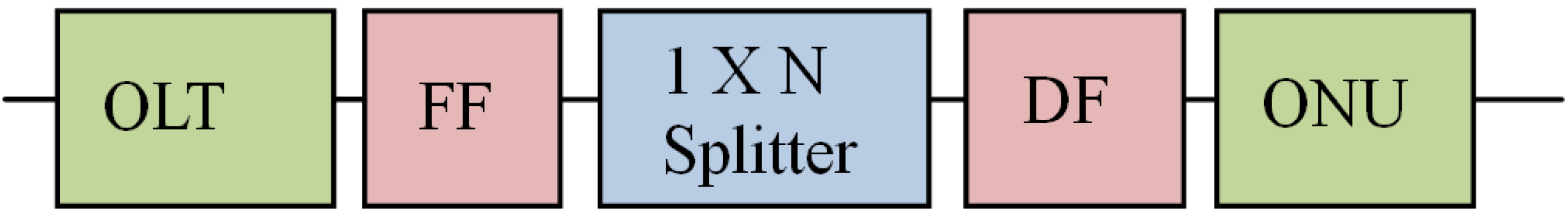
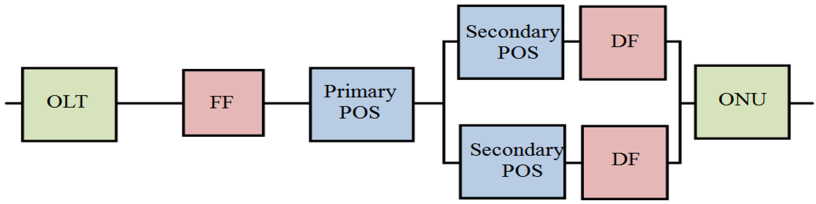
  • Make a reliability analysis of the communication network, consisting of OLT, feeder fiber (FF), passive optical splitter (POS), distributed fiber (DF), and ONU;
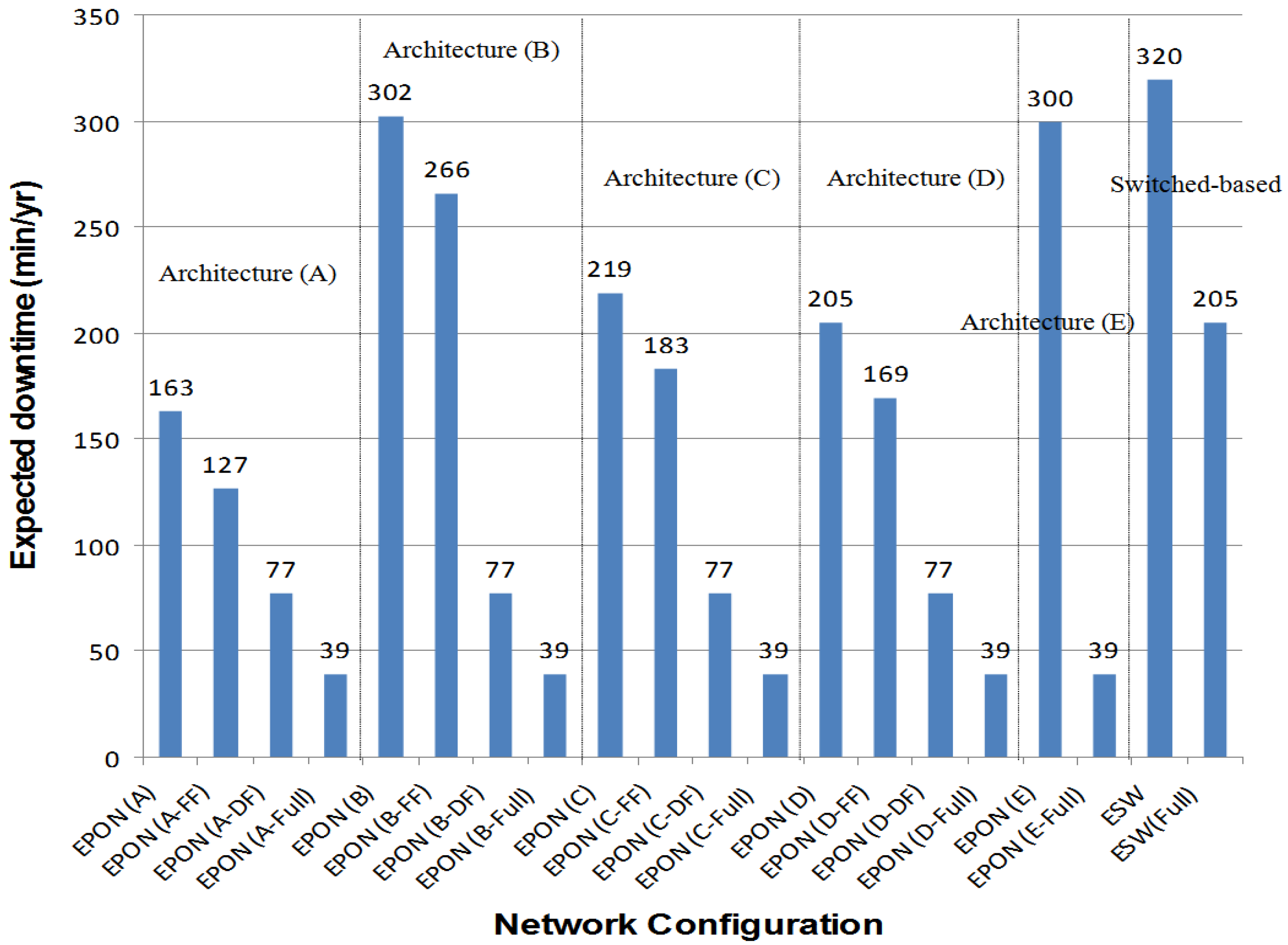
  • Compare the connection availability between OLT and WT-ONUs with different protection schemes; and
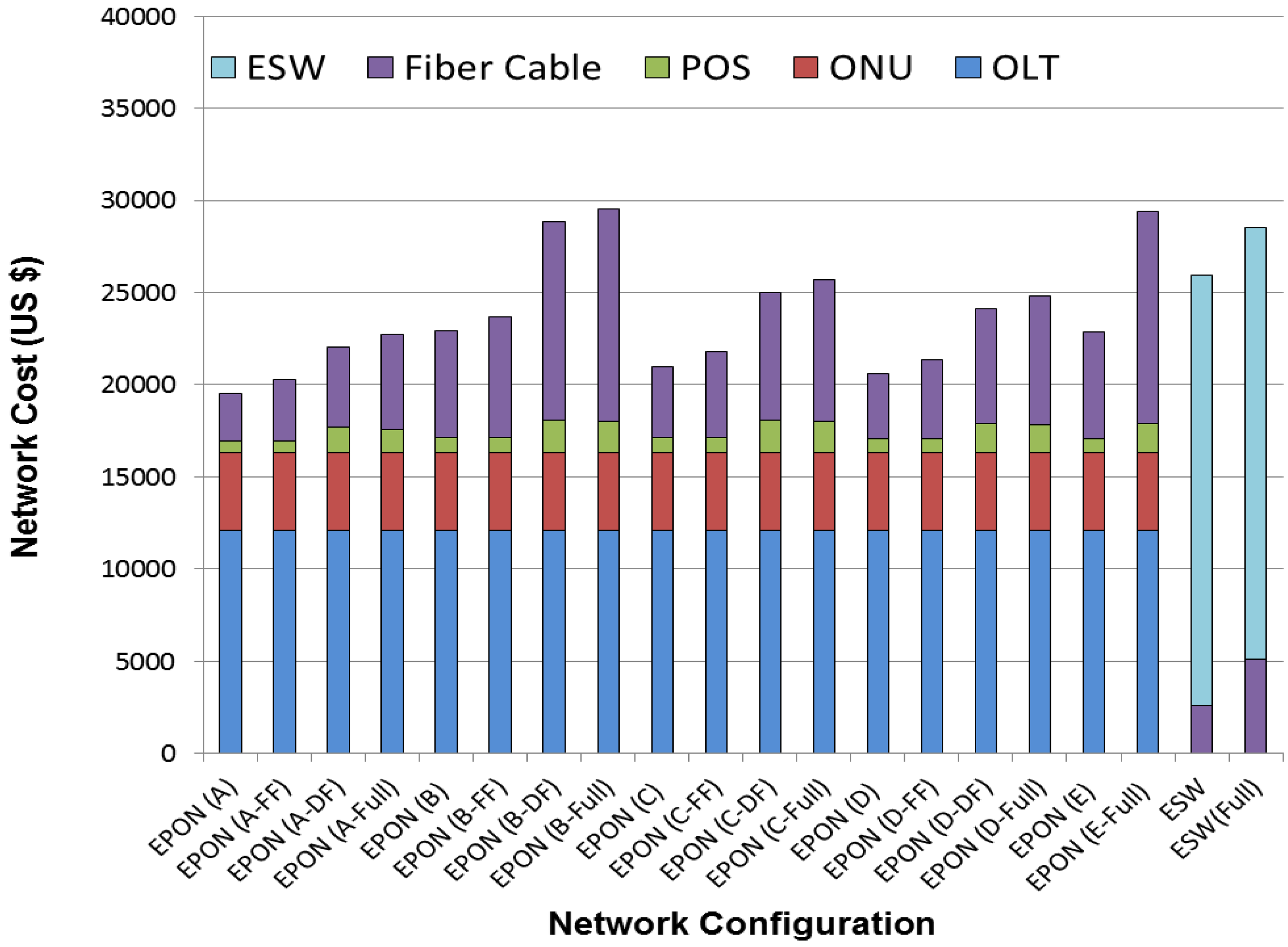
  • Compare the network costs for 20 different architectures with, and without, protection schemes.
This paper is structured as follows. Section 2 provides related work. In Section 3, the proposed EPON-based wind power farm topologies are described. Section 4 provides the performance evaluation, results, and discussion. Finally, Section 5 presents the conclusion and the direction of future work.

2. Related Work

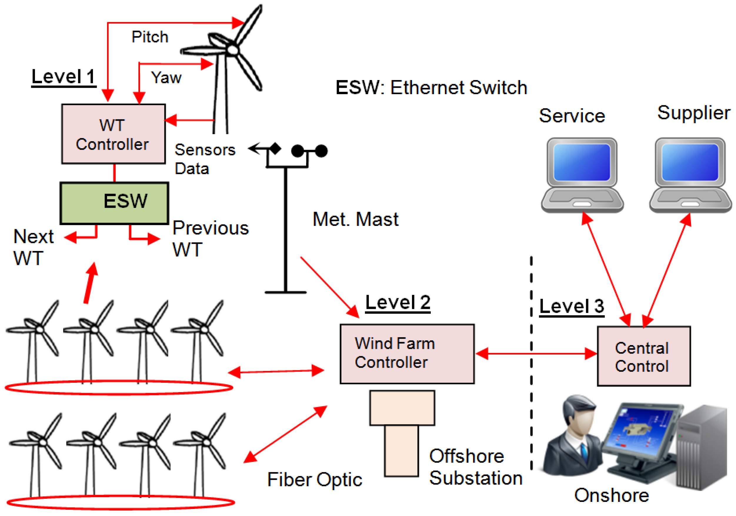
2.1. Communication Network for Wind Power Farms (WPFs)

The supervisory control and data acquisition (SCADA) system enables operators to monitor, control and record data of a wind power plant, from a remote place called a central control station [8,9,10]. It consists of three main components as shown in Figure 1.
  • Inside the turbine tower, including the wind turbine controller (WTC), remote terminal units (RTU), intelligent electronic devices (IEDs), and sensors. The WTC collects all data using short communication links, and makes them available for processing and transferring to the control center. The closed-circuit television (CCTV) system and the Internet connection may share or use an independent communication network between the wind turbine and the control center.
  • Communication network based on Ethernet equipment (gigabit Ethernet switch) is considered, to transfer data between the WTs and the control center. Most WPFs use the same power cable routes for the SCADA communication network as for the power distribution.
  • Control center connects individual WTs and meteorological stations to the control center. It enables the operators to manage the behavior of all WTs as a whole. It requires a long distance for data transmission.

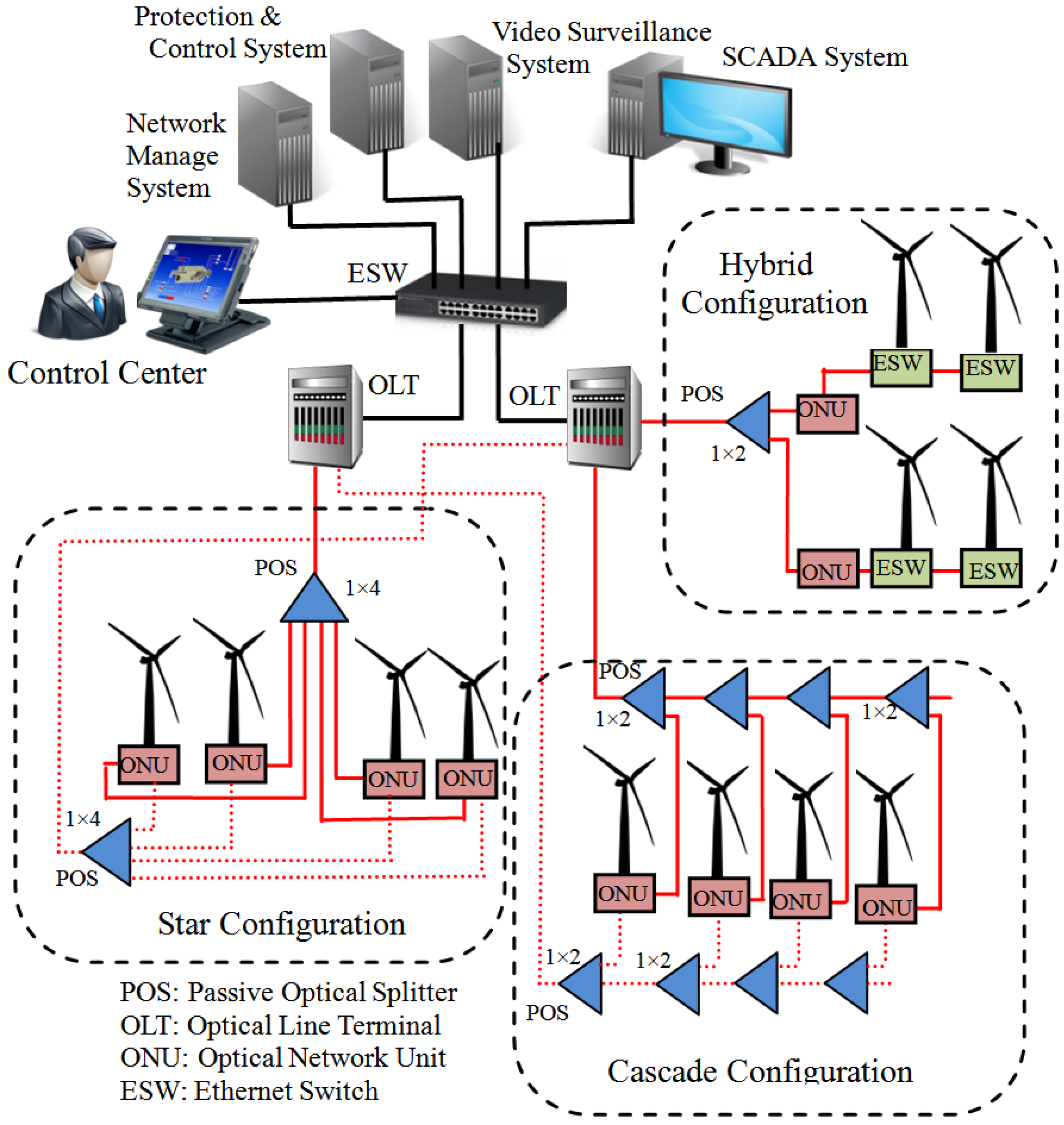
2.2. Ethernet Passive Optical Network (EPON)-Based Communication Network for WPFs

EPON consists of an OLT located in the control center, multiple ONUs, and POS. In the downstream direction, EPON is a point-to-multipoint network; the OLT broadcasts control messages and data packets to all ONUs through a passive splitter. In the upstream direction, EPON is a multipoint-to-point network; multiple ONUs transmit data to the OLT through a passive combiner [11].
Figure 2 shows a schematic view of the proposed EPON-based communication network for WPF [12]. The proposed network consists of an optical network device (ONU) deployed on the WT’s side for collecting different data, including wind turbine operation, meteorological data, fault parameters, and security from different internal networks. All ONUs from different WTs are connected to an OLT unit, placed on the control center side. The path between WTs and the control center does not contain any active elements, which saves costs and reduces the complexity of maintenance and deployment, compared with current switched gigabit Ethernet.
In Figure 2, the proposed architectures (star, cascade, etc.) represent the structure design of new planned WPFs. The hybrid configuration (Ethernet switch and ONU) represents modifying existing WPFs to support EPON technology, which is out of the scope of this work. In a star configuration, four wind turbines are connected with distributed fibers to the control center using one POS (1 × 4). In the cascade configuration, four POS (1 × 2) are connected in cascade; one port is connected to the next WT, while the other port is connected to the WT-ONU unit.
In this work, EPON uses a 1-Gbps single fiber, with a transmission range of 20 km. Two different wavelengths are used to support downstream and upstream transmission, 1490 nm and 1310 nm, respectively. Each WT transmits data in its time slots, to avoid data collisions. EPON must employ a medium access control (MAC) mechanism, to arbitrate access to the shared medium, to prevent different ONU′s data from colliding in the upstream direction. OLT efficiently shares the upstream transmission bandwidth among all turbines′ ONUs. Failure to gain access to this shared channel in a timely manner could negatively impact the communication and should be considered as an aspect of reliable communication. There have been many studies and frameworks for managing the medium access control in [13,14,15,16].

3. Proposed EPON-Based WPF Topologies

This section considers a small scale WPF, consisting of 12 WTs, with a generated power of 60 MW, close to the grid (5 km). All WTs are connected together in a radial topology (WT1 ➔ WT6 and WT7 ➔ WT12). Five different architectures (A, B, C, D, and E) are proposed. Among the five mentioned architectures, any other WPF layout can be constructed. We assumed that:
  • An OLT is installed in the control center;
  • Each WT has only one ONU device;
  • All internal networks inside a WT (which include monitoring, protection, and security) may be connected with one or more ONU buffers; and
  • Different network architectures are designed, using FF, DF, and POS.

3.1. Architecture (A)

This begins with an OLT unit located in the control center, connected with a 5 km feeder fiber to the first wind turbine (WT1). Cascade splitters are used to reduce the amount of deployed fiber in the network. WT1 has two POS (primary and secondary); both are (1 × 2). The primary POS has two output ports; one is connected to WT1, while the other is connected to WT7. For all other WTs (WT2 ➔ WT12), each WT has only one POS (1 × 2); one port is connected using DF to the next WT, while the other port is connected to the WT-ONU unit. All DFs in this architecture are of 1 km length (the distance between WTs). Note that, POS (1 × 2) is used in both WT6 and WT12, in order to help extend the network, in case of installing new WTs (one port is used, while the other is left empty). Figure 3 shows the network elements of architecture (A).

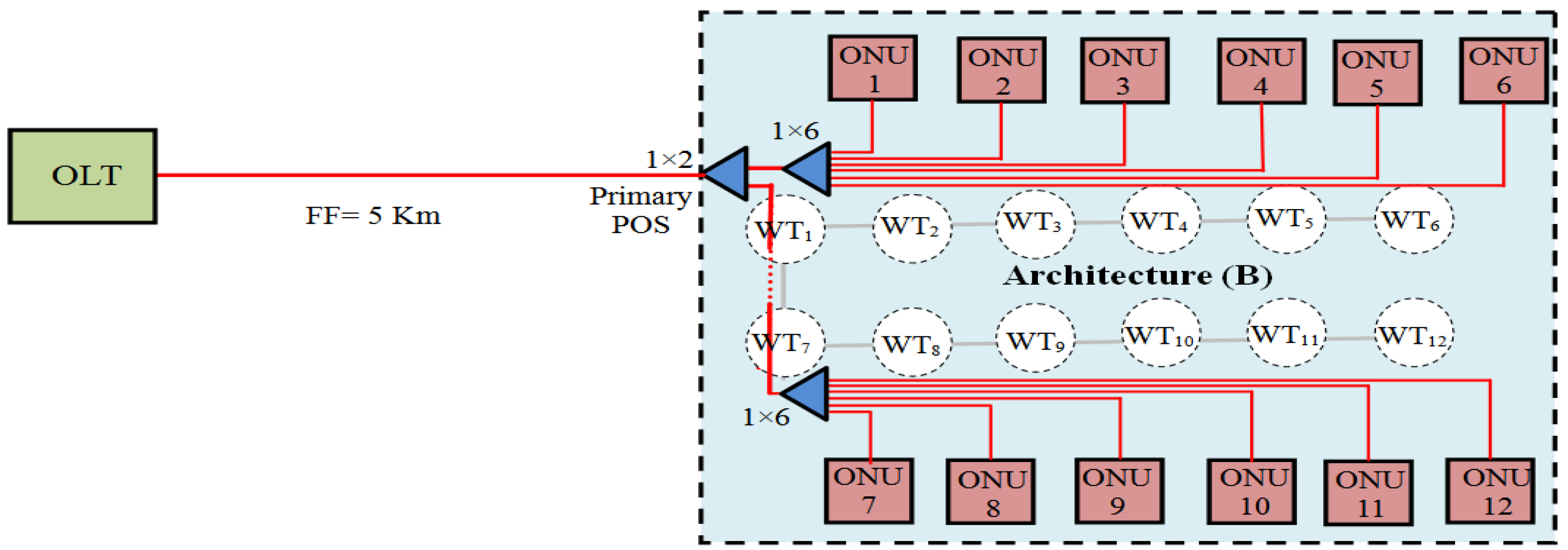
3.2. Architecture (B)

This differs from architecture (A), as it has three POS (one primary POS and two secondary POS). The primary POS is (1 × 2), the same as architecture (A). The first secondary POS is (1 × 6) in WT1, with six outputs. Each WT from (WT1 WT6) has dedicated optical fiber cable from secondary POSs located in WT1. Additionally, the secondary POS in WT7 is (1 × 6), and connects via a dedicated path to (WT7 ➔ WT12). Figure 4 shows the network elements of architecture (B).

3.3. Architecture (C)

This combines the advantage of both configurations (A) and (B) of low fiber deployment and less number of POS. It differs from architecture (B), as it has five POS (one primary POS and four secondary POS). All secondary POS are (1 × 4), in WT1, WT4, WT7, and WT10. In WT1, three output ports from secondary POS are connected to (WT1–WT3), the remaining port is connected to another POS (1 × 4) exist in WT4 with four output ports. The remaining ports of POS in WT4 and WT10 are left for future extensions. Figure 5 shows the network elements of architecture (C).

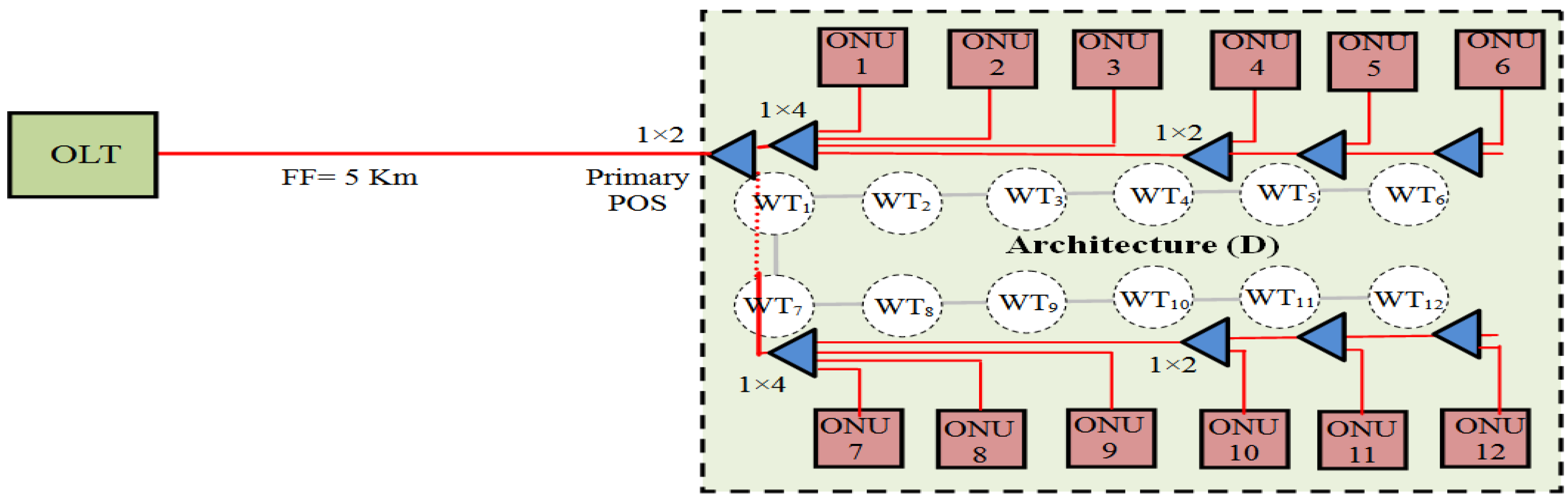
3.4. Architecture (D)

It is a modification of architecture (C). Each WT from (WT4–WT6) and (WT10–WT12) has only one POS (1 × 2); one port is connected using DF to the next WT, while the other port is connected to the WT-ONU unit. Both architecture (C) and architecture (D) can be expandable to include more WTs. Architecture (D) has more POSs than architecture (C). Howerver, architecture (D) has less fiber deployment. Figure 6 shows the network elements of architecture (D).

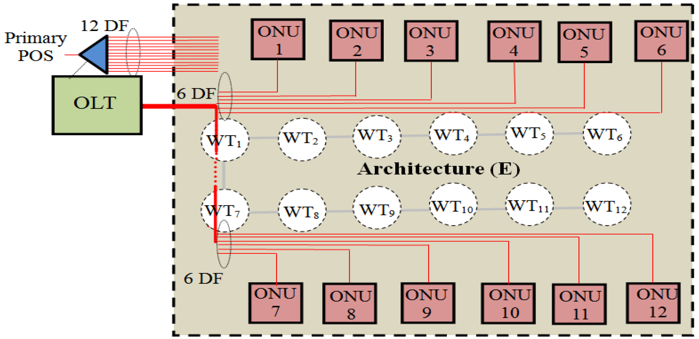
3.5. Architecture (E)

This architecture can be applied to small-scale onshore WPF, with WTs distributed around the control center, as shown in Figure 7. It is similar to architecture (B), with the only difference being that only one primary POS (1 × 12) is used, and it resides in the control center. The length of the feeder fiber to WT1 is neglected, where WT1 is nearby the control center. The advantage of this architecture is that the serviceability of the network is improved, as all network hardware is located in the control center. Additionally, this architecture reduces the costs and complexity of maintenance and deployment.
A disadvantage of architecture (E) is the large amount of distributed optical fibers is used. Table 1 shows the details of network elements for the proposed EPON-based network architectures, where an OLT unit is located at the control center and 12 ONUs are deployed on the WTs side.

4. Performance Evaluation

4.1. Optical Power Budget

The optical power budget is analyzed to ensure that the received signal power is enough to maintain acceptable performance even though the lengths of communication links between the control center and WTs are different. The power budget for EPON specified in IEEE 802.3ah standard is 26.0 dB in the case of 1000 Base-PX20, for both upstream and downstream traffic. The optical budget [dB] is defined as the difference between the minimum transmitter launch power (Ptx, dBm) at the input of the optical link, and the minimum sensitivity of the receiver (Prx, dBm) at the output of optical links [17,18,19] as shown in Equation (1):
Power Budget  = P t x P r x
There are many sources of attenuation including splitters (LossPOS), connectors (Lossconn), and the fiber cable itself (Lossfiber). The total optical power loss (PLoss) of optical link given in [dB] is calculated as shown in Equation (2):
P L o s s = L o s s P O S + L o s s C o n n + L o s s F i b e r
Table 2 shows the EPON specification according to IEEE 802.3ah standard. The component insertion loss is shown in Table 3. We considered the fiber attenuation is 0.4 dB/km, and the connector loss is 0.2 dB. Passive optical splitter (1 × 2) insertion loss is 0.4 dB for a split ratio of 5:95, while the insertion loss is 3 dB for split ratio of 50:50.
Figure 8 shows the total optical path loss calculation for the five different configurations. The highest optical path loss value represents the farthest turbine, while the lowest value represents the nearest turbine. For example, the highest optical path loss value is about 20.2 dB for WT12 in architecture (C), while the lowest value is about 6.6 dB for WT1 in architecture (A). In architecture (A), with 1 km between WTs, fiber attenuation is 0.4 dB, connector loss is 0.4 dB and POS (1 × 2) has insertion loss of 0.4 dB. This is the reason why the total optical path loss is growing linearly.
The analysis of optical power budget shows that architecture (A) offers a lower optical path loss among other architectures due to a small insertion loss of POS (1 × 2). However, architecture (B) has a higher optical path loss due to a higher splitting ratio and length of fiber cables. Architecture (C) and architecture (D) combine the advantage of both configuration (A) and configuration (B).

4.2. Reliability

In this section, a reliability analysis of EPON-based communication network between OLT and WT-ONUs for a small-size offshore WPF is given. Five basic topologies without any redundancy (architecture A, B, C, D, and E) are constructed. Since redundancy for collector systems in WPFs considers additional cables for protection, we consider additional FF, POS, and DF as network protection components. Failure rate and mean time to repair (MTTR) are considered, based on network components from reference [20,21,22].
The following assumptions are considered in our study:
  • The WTs used in this study are 5 MW. The distance between two WTs is 1 km.
  • Reliability analysis considers only the communication network between the OLT and ONUs. It consists of OLT, FF, POS, DF, and ONU.
  • We assume that the failure rate of the OLT and ONU is small, compared with the number of failures in cables. Therefore, the equipment failures of OLT and ONUs are neglected in our analysis.
  • The communication network equipment inside each WT is not considered, and only the ONU is considered in our calculation.

4.2.1. Reliability Block Diagram

We consider time division multiplexing passive optical network (TDM-PON) architecture defined by international telecommunication union-telecommunication sector (ITU-T), with basic architecture and protection schemes [23]. The reliability block diagram for basic PON without protection is shown in Figure 9, where each block in the diagram represents either a component or a fiber link. For each block, a characteristic parameter of unavailability is given in Table 4.
The series configuration, from a reliability point of view, means that a system fails if one or more of its components fail [24,25]. Using the failure rate of a communication network component (OLT, POS, Fiber, and ONU), unavailability of a component (Ux) is derived from its failure rate in FIT (1 FIT = 1 failure/109 h), and the mean repair time (MTTR) in hours, as shown in Equation (3). Equation (4) shows the mean down time (MDT) in (min/year) for component x (MDTx):
U X = ( Failure rate  ×  MTTR x ) / 10 9
MDT X = ( U X × 365 × 24 × 60 )
The expression for the connection unavailability (UEPON) for EPON-based architecture without protection is given in Equation (5), where, UOLT, UFF, UPOS, UDF, and UONU are the unavailability of OLT, FF, POS, DF, and ONU, respectively.
U E P O N = U O L T + U F F + U P O S + U D F + U O N U
For example, architecture (A) has a minimum number of fiber deployments, by using cascaded splitters with FF = 5 km and DF = 11 km. The expected downtime for architecture (A) is 163 min/year.

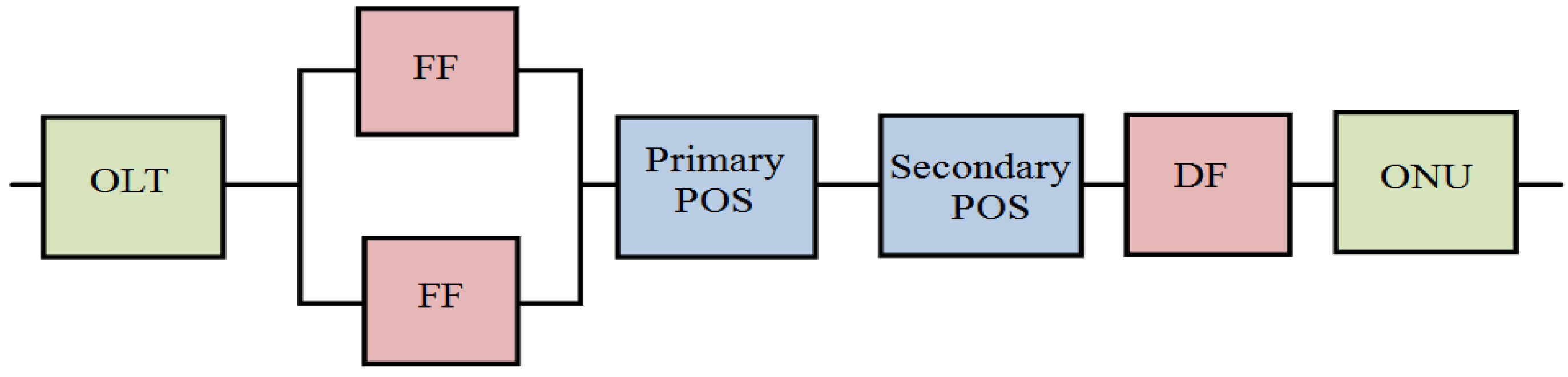
4.2.2. EPON-based Protection Schemes

Redundancy is a major way to enhance the reliability of WPF communication network. There are two types of redundancy, device redundancy (OLT and ONU), and fiber redundancy (FF and DF). We assume that the failure rate of the OLT and ONU is small, compared with the number of failures in cables. Therefore, protection of both OLT and ONUs are neglected in our analysis. In feeder fiber protection architecture, only the FF is protected as shown in Figure 10. In this case, the feeder fiber is normally working, while the spare fiber is in standby. In the case of FF failure, the OLT is responsible for switching to the spare fiber. In a full protection architecture, all network components are fully duplicated.
There are three different protection architectures; category (1) represents architectures with feeder fiber protection; one is working, while the other is in standby. In category (2), DFs are duplicated, and also secondary POS are changed to support the redundancy in the DF, as shown in Figure 11. In the last category (3), all architectures enjoy full protection, with all network components duplicated as shown in Figure 12.
We calculated the unavailability of 20 different network architectures, using the component reliability data of Table 4 and Equations (6–8). Note that, the MTTR for the OLT is considered as only 4 h, as it is located in the control center. All other network components located on the WT side are considered to take 24 h to repair, in case of a fault.
U E P O N ( F F ) = U O L T + ( U F F ) 2 + U P O S + U D F + U O N U
U E P O N ( D F ) = U O L T + U F F + U P O S 1 + ( U P O S 2 + U D F ) 2 + U O N U
U E P O N ( D F ) = U O L T + ( U F F + U P O S 1 + U P O S 2 + U D F ) 2 + U O N U
Figure 13 shows the expected downtime for different network architectures. In the case of an unprotected network, architecture (A) has the lowest MDT of about 163 min/year, while architecture (E) has the highest MDT, of about 300 min/year, as shown in Figure 13. In the case of full protection, all three architectures have the same MDT, of about 39 min/year. As we can see, conventional switched-based architecture has the highest downtime of about 320 min/year for an unprotected network configuration, while about 205 min/year downtime for full protection configuration.

4.3. Network Cost

Capital expenditure (CAPEX) consists of both initial network equipment and network installation costs [25,26]. In this work, the power cable line comprises the electrical collection cables and optical fiber cables. Since the communication network part is integrated with the electrical system, we consider only the network equipment cost to evaluate and compare different network architectures.
The communication network cost can be divided into active device costs (OLT, ONU, and Ethernet switch) and passive component costs (POS and fiber). The total network cost for the EPON-based and switch-based architectures can be represented as follows:
C E P O N = C O L T + C F F + C P O S + C D F + C O N U × N O N U
C E t h e r n e t = C E S W + C F F + C D F
where, COLT, CPOS, CESW, and CONU represent the equipment of the OLT, Ethernet switch, POS, and ONU, respectively. CFF and CDF represent the costs of optical fiber cable of the feeder fiber and distributed fiber, respectively. NONU represents the number of WT-ONUs.
The equipment costs used in our model are detailed in Table 5. We consider that the OLT cost is $12,100, and the ONU cost is $350. As expected, unprotected EPON is the most economic deployment solution for EPON-based architectures, compared with the conventional switched-based architectures.
In Figure 14, results show that the network cost of architectures (A, C, and D) with full protection is lower than unprotected architecture for conventional switched-based architectures. Using the results obtained of reliability analysis and network cost, an effective and highly reliable WPF architecture can be chosen and deployed.

5. Conclusions

In this paper, we propose an EPON-based communication network architecture for a small-size offshore WPF. The main objective aims to deploy ONUs on the WT side, for collecting data from different internal networks. The path between WTs and the control center does not contain any active elements, compared with current switched gigabit Ethernet. The reliability block diagram approach is used to calculate the availability between the OLT and WT-ONUs, for five different architectures (A, B, C, D, and E). Based on ITU-T, three different protection schemes (FF, DF, and Full) are configured, explained, and discussed. In view of network availability, results show that the unprotected architecture (A) has the lowest MDT of about 163 min/year; while in the case of full protection, the three architectures have similar MDT of about 39 min/year. In view of network cost, architecture (A) has the lowest network cost. In addition, architectures (A, C, and D) with full protection are lower in network cost than unprotected architectures for conventional switched-based architecture. We can conclude that architecture (A) has the best performance in view of both network availability and network cost. An effective and highly reliable WPF architecture can be chosen to be deployed by considering the numerical results of optical path loss, reliability analysis, and network cost.

Acknowledgments

This work was supported by the Brain Korea 21 PLUS and the National Research Foundation of Korea (NRF) grant funded by the Korea government (MSIP) (2010-0028509).

Author Contributions

Mohamed A. Ahmed and Young-Chon Kim proposed the communication network architectures of this paper; Jae-Kyung Pan and Minho Song helped in analysis of the results; Young-Chon Kim provided guidance during the whole research.

Conflicts of Interest

The authors declare no conflict of interest.

References

  1. Zaker, N.; Kantarci, B.; Erol-Kantarci, M.; Mouftah, H.T. Smart grid monitoring with service differentiation via EPON and wireless sensor network convergence. Opt. Switch. Netw. 2014, 14, 53–68. [Google Scholar] [CrossRef]
  2. Raza, A.; Ullah, K.; Ahmed, S.; Hyuk-Soo, J.; Hyo-Sik, Y. Baseline Efficiency in EPON Based Architecture to Inter-Network Substations. In Proceedings of the IC4 2009: 2nd International Conference on Computer, Control and Communication, Karachi, Pakistan, 17–18 February 2009; pp. 1–6.
  3. Jiang, H.; Yao, J.; Zhang, G. The construction scheme analysis of distant communication systems for subscriber power consumption information acquisition systems. J. Int. Counc. Electr. Eng. 2011, 1, 482–485. [Google Scholar] [CrossRef]
  4. Yao, H.; Peng, Q.; He, W.; Zhang, X. Integrated Communication Technology for Supervisory Control and Data Acquisition System of PV Power Station. In Proceedings of the ISDEA 2012: 2nd International Conference on Intelligent System Design and Engineering Application, Sanya, China, 6–7 January 2012; pp. 1277–1280.
  5. Kanabar, M.; Sidhu, T.S. Reliability and Availability Analysis of IEC 61850 Based Substation Communication Architectures. In Proceedings of the IEEE PES Power and Energy Society General Meeting 2009, Calgary, AB, Canada, 26–30 July 2009; pp. 1–8.
  6. Ali, I.; Thomas, M.S.; Gupta, S.; Hussain, S.M.S. IEC 61850 substation communication network architecture for efficient energy system automation. Energy Technol. Policy 2015, 2, 82–91. [Google Scholar] [CrossRef]
  7. Franken, B. Reliability Study. Analysis of Electrical Systems within Offshore Wind Parks, Elforsk Report 07:65; Elforsk: Stockholm, Sweden, November 2007; Available online: http://www.elforsk.se/Global/Vindforsk/Rapporter%20fran%20Vindforsk%20II/V-118%20R_07_65.pdf (accessed on 10 January 2016).
  8. Gardner, P.; Craig, L.M.; Smith, G.J. Electrical Systems for Offshore Wind Farms. In Proceedings of the European Wind Energy, 20th BWEA Conference, Cardiff, UK, 2–4 September 1998; pp. 1–9.
  9. Pettener, A.L. SCADA and Communication Networks for Large Scale Offshore Wind Power Systems. In Proceedings of the RPG 2011: IET Conference on Renewable Power Generation, Edinburgh, UK, 6–8 September 2011; pp. 1–6.
  10. Ahmed, M.A.; Kim, Y.C. Communication network architectures for smart-wind power farms. Energies 2014, 7, 3900–3921. [Google Scholar] [CrossRef]
  11. Maier, M.; Ghazisaidi, N. QoS provisioning techniques for future fiber-wireless (FiWi) access networks. Future Internet 2010, 2, 126–155. [Google Scholar] [CrossRef]
  12. Ahmed, M.A.; Yang, W.H.; Kim, Y.C. Communication Network Architectures Based on EPON for Offshore Wind Power Farm. In Proceedings of the ENERGY 2013: 3rd International Conference on Smart Grids, Green Communications and IT Energy-aware Technologies, Lisbon, Portugal, 24–29 March 2013; pp. 15–20.
  13. Kramer, G.; Pesavento, G. Ethernet passive optical networks (EPON): Building a next-generation optical access network. IEEE Commun. Mag. 2002, 40, 66–73. [Google Scholar] [CrossRef]
  14. Kantarci, B.; Mouftah, H.T. Bandwidth distribution solutions for performance enhancement in long‐reach passive optical networks. IEEE Commun. Surv. Tutor. 2012, 14, 714–733. [Google Scholar]
  15. McGarry, M.P.; Reisslein, M. Investigation of the DBA algorithm design space for EPONs. J. Lightwave Technol. 2012, 30, 2271–2280. [Google Scholar]
  16. Li, X.; Dan, L.; Wu, Q. Adaptive dynamic bandwidth allocation algorithm supporting multi-services over Ethernet passive optical networks. Opt. Int. J. Light Electron Opt. 2013, 124, 287–291. [Google Scholar]
  17. IEEE Standard 802.3ah, IEEE‐SA Standard Board, June 2004. Available online: http://www.ieee802.org/21/doctree/2006_Meeting_Docs/2006-11_meeting_docs/802.3ah-2004.pdf (accessed on 10 January 2016).
  18. Ng, B.; Syuhaimi, M.; Premadi, A.; Jumari, K. Optical power budget and cost analysis in PON-based I-FTTH. Res. J. Inf. Technol. 2010, 2, 127–138. [Google Scholar] [CrossRef]
  19. Huang, H.; Zhang, H. Application and analysis of long distance EPON in transmission lines monitoring system. Adv. Mater. Res. 2011, 317–319, 1583–1589. [Google Scholar] [CrossRef]
  20. Chen, J.; Kantor, M.; Wajda, K.; Wosinska, L. Next-Generation FTTH Passive Optical Networks: Research towards Unlimited Bandwidth Access; Prat, J., Ed.; Springer: Dordrecht, Netherlands, 2008. [Google Scholar]
  21. Kourtessis, P; Almeida, C.; Chang, C.H.; Chen, J.; Di Bartolo, S.; Fasser, P.; Gagnaire, M.; Leitgeb, E.; Lima, M.; Löschnigg, M.; et al. Evolution of Optical Access Networks. In Towards Digital Optical Networks; Springer: Berlin, Germany, 2009; Volume 5412, pp. 97–131. [Google Scholar]
  22. Ahmed, M.A.; Yang, W.H.; Kim, Y.C. Performance Evaluation of EPON-Based Communication Network Architectures for Large-Scale Offshore Wind Power Farms. In Multimedia and Ubiquitous Engineering; Springer: Dordrecht, Netherlands, 2013; Volume 240, pp. 841–848. [Google Scholar]
  23. ITU-T G.983.1, Broadband Optical Access Systems based on Passive Optical Networks (PON), October 1998. Available online: https://www.itu.int/rec/T-REC-G.983.1-199810-S/en (accessed on 10 January 2016).
  24. Machuca, C.M.; Wosinska, L.; Chen, J. Assessment methodology of protection schemes for next generation optical access networks. Opt. Fiber Technol. 2015, 26, 82–93. [Google Scholar] [CrossRef]
  25. Wosinska, L.; Chen, J.; Larsen, C.P. Fiber access networks: Reliability analysis and Swedish broadband market. IEICE Trans. Commun. 2009, E92-B, 3006–3014. [Google Scholar] [CrossRef]
  26. Fernández, Á.; Stol, N. CAPEX and OPEX simulation study of cost-efficient protection mechanisms in passive optical networks. Opt. Switch. Netw. 2015, 17, 14–24. [Google Scholar] [CrossRef]
Figure 1. Schematic view of conventional wind power farms (WPF) network.
Applsci 06 00081 g001
Figure 2. Schematic view of proposed Ethernet Passive Optical Network (EPON) communication network for WPF.
Applsci 06 00081 g002
Figure 3. EPON-based architecture (A).
Applsci 06 00081 g003
Figure 4. EPON-based architecture (B).
Applsci 06 00081 g004
Figure 5. EPON-based architecture (C).
Applsci 06 00081 g005
Figure 6. EPON-based architecture (D).
Applsci 06 00081 g006
Figure 7. EPON-based architecture (E).
Applsci 06 00081 g007
Figure 8. Total optical path loss for different architectures.
Applsci 06 00081 g008
Figure 9. Reliability block diagram for unprotected EPON architecture.
Applsci 06 00081 g009
Figure 10. Reliability block diagram for feeder fiber (FF) protection architecture.
Applsci 06 00081 g010
Figure 11. Reliability block diagram for (distributed fiber) DF protection architecture.
Applsci 06 00081 g011
Figure 12. Reliability block diagram for Full protection architecture.
Applsci 06 00081 g012
Figure 13. Mean down time for different architectures for a small (wind power farms) WPF.
Applsci 06 00081 g013
Figure 14. Network cost for WPF architectures.
Applsci 06 00081 g014
Table 1. Network elements of small wind power farms (WPF) (unprotected).
EPONOLTFF (km)Number Primary POSNumber Secondary POSNumber Other POSDF (km)
A151 (1 × 2)12 (1 × 2)-11
B151 (1 × 2)2 (1 × 6)-31
C151 (1 × 2)4 (1 × 4)-19
D151 (1 × 2)2 (1 × 4)6 (1 × 2)17
E1-1 (1 × 12)--36
WPF: wind power farm; EPON: Ethernet Passive Optical Network; OLT: optical line terminal; FF: feeder fiber; POS: passive optical splitter; DF: distributed fiber.
Table 2. IEEE STD 802.3 EPON specifications.
ParameterData RatePower Budget
EPON1.25 Gbps
(D and U)
1000Base-PX20
PX-20U 26 dB
PX-20D 26 dB
Table 3. Component insertion loss.
ComponentAttenuation
Fiber0.4 dB/km
Connector0.2 dB
Splitter1 × 2 (5%:95%) ➔ 0.4 dB
1 × 2 (50%:50%) ➔ 3.0 dB
1 × 4 ➔ 6.0 dB
1 × 8 ➔ 9.0 dB
1 × 16 ➔ 12.0 dB
Table 4. Reliability data [22].
ComponentsFailure Rate (FIT) *MTTR (h)Unavailability
OLT25641.024 × 10−6
ONU256246.144 × 10−6
Switch1250243.00 × 10−5
1:2 Splitter50241.20 × 10−6
1:N (2:N)
Splitter
12024
6
2.88 × 10⁻⁶
7.20 × 10⁻⁷
Fiber (per km)570/km241.368 × 10−5
MTTR: mean time to repair; * 1 FIT = 1 failure/109 h.
Table 5. Component cost (US $) [22].
ParameterCost (US $)
OLT12100
ONU350
ESW1800
Splitter (1 × 2)50
Splitter (1 × N)(50 per port)
Fiber (per km)160

