
A Study on the Design of the Top Flange of a Modular T-Girder Bridge Using the Limit State Design Method

Abstract
:
1. Introduction
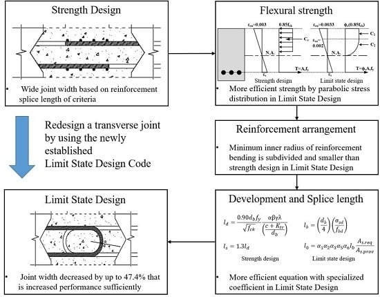
2. Design Progress
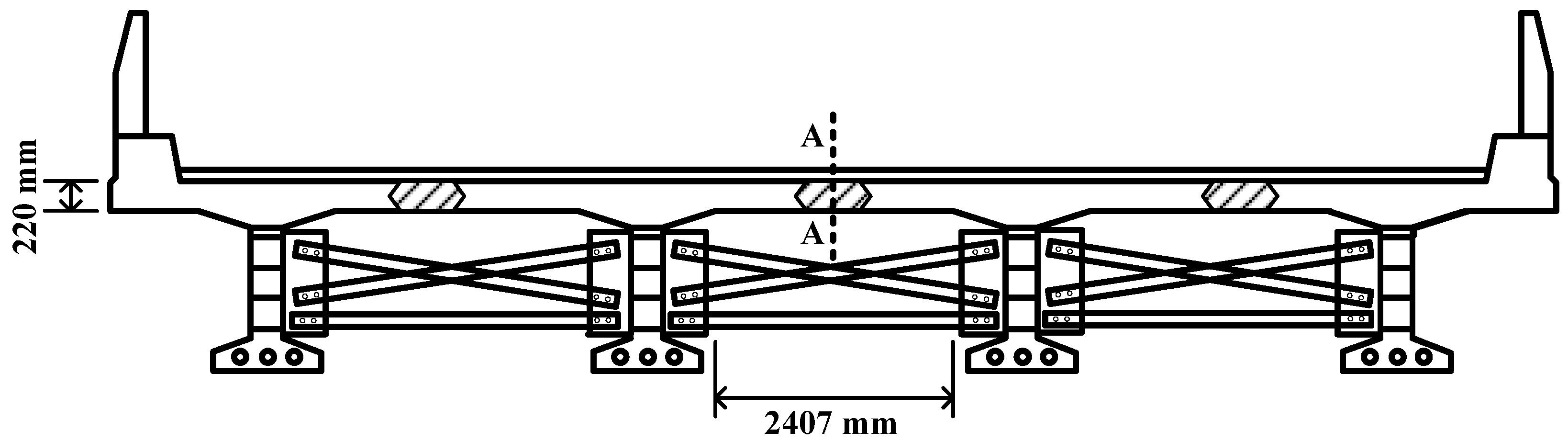
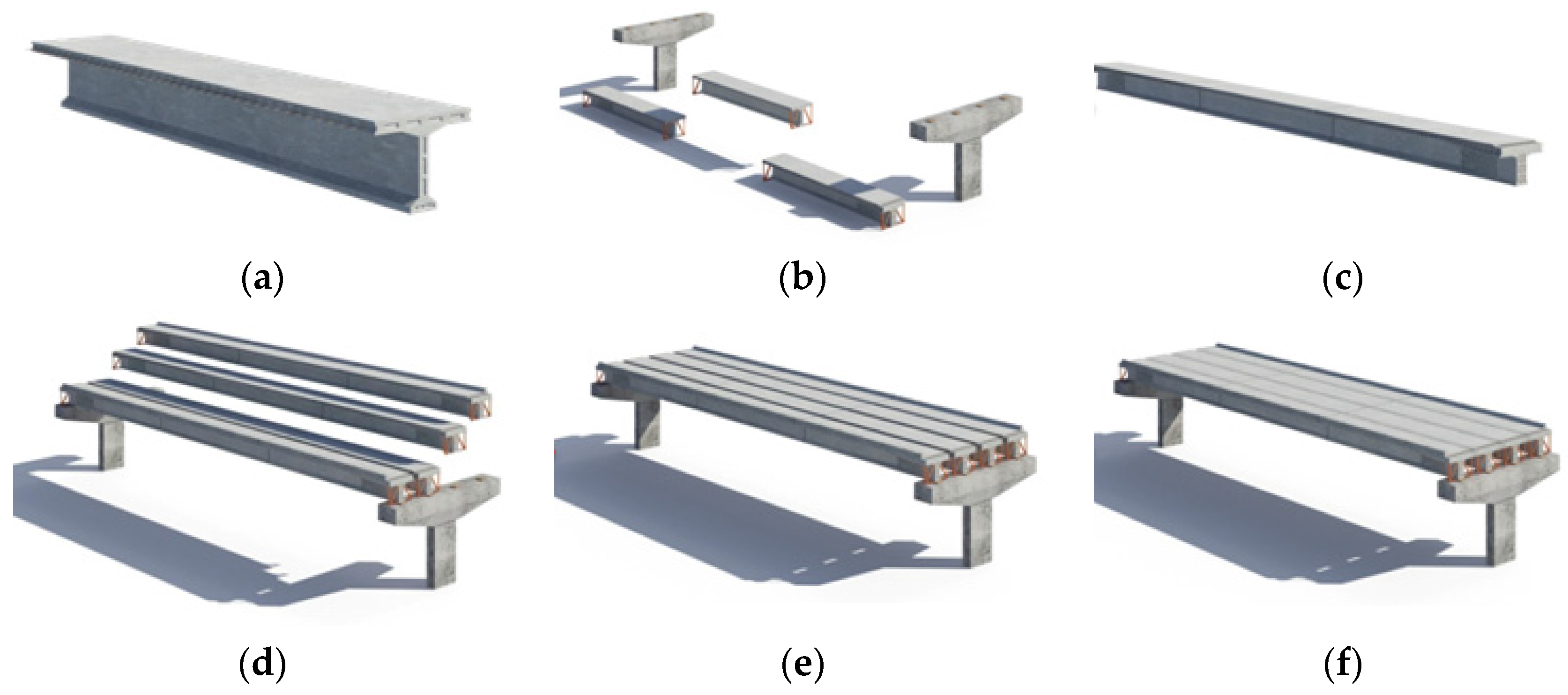
2.1. Current Modular Bridge
2.2. Design
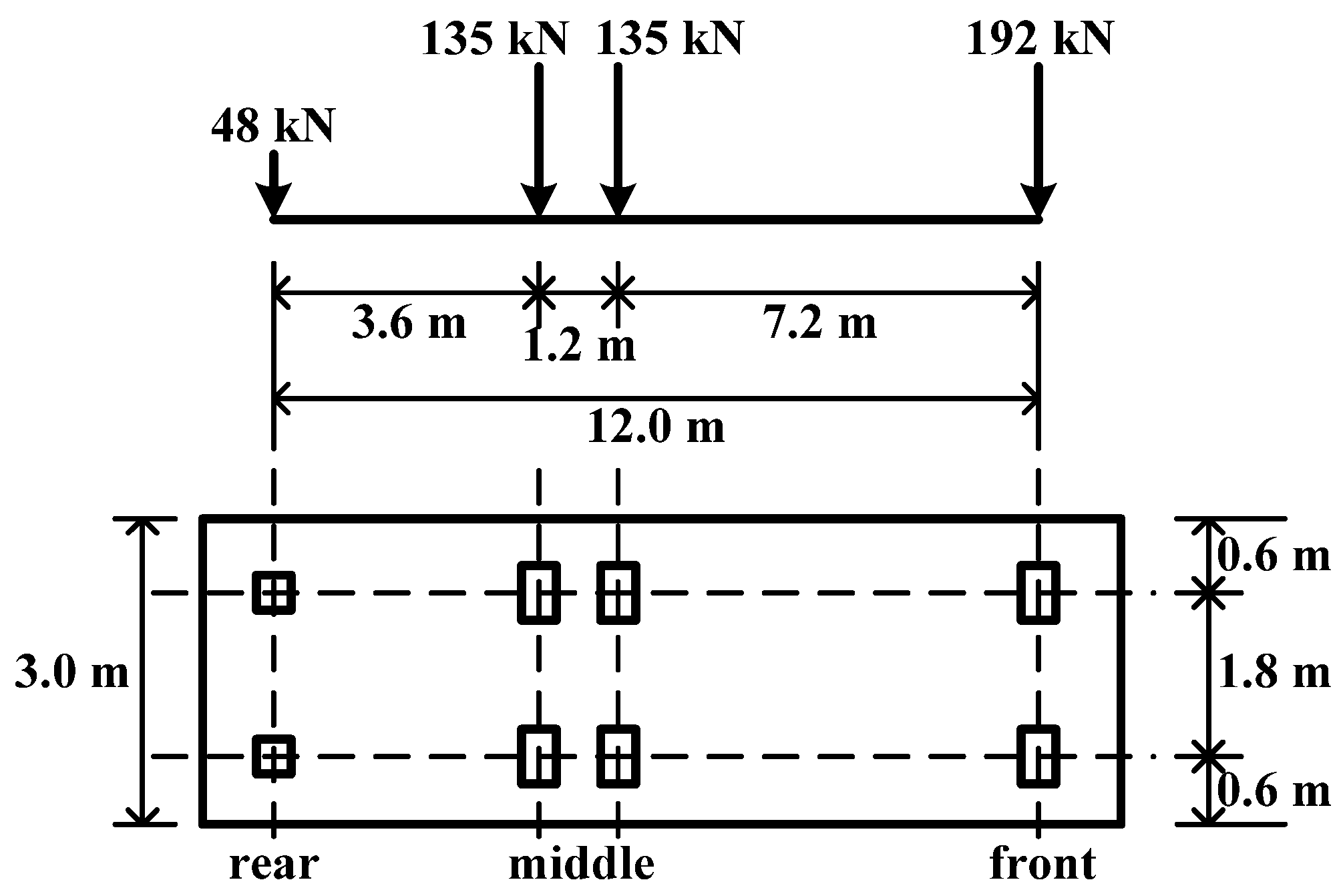
2.2.1. Load
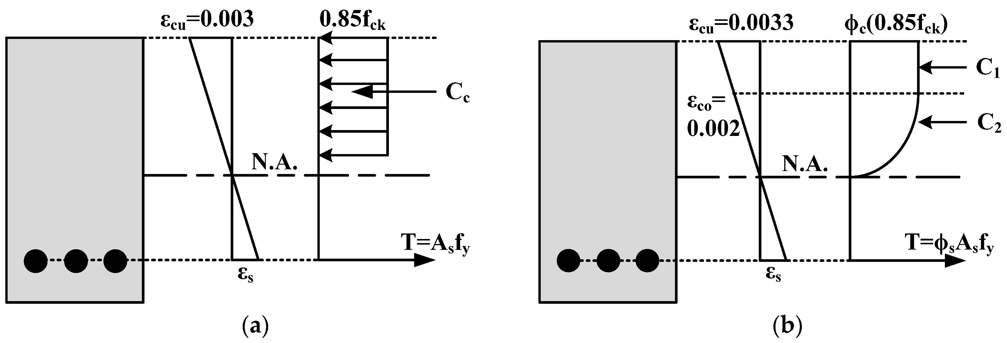
2.2.2. Flexural Strength
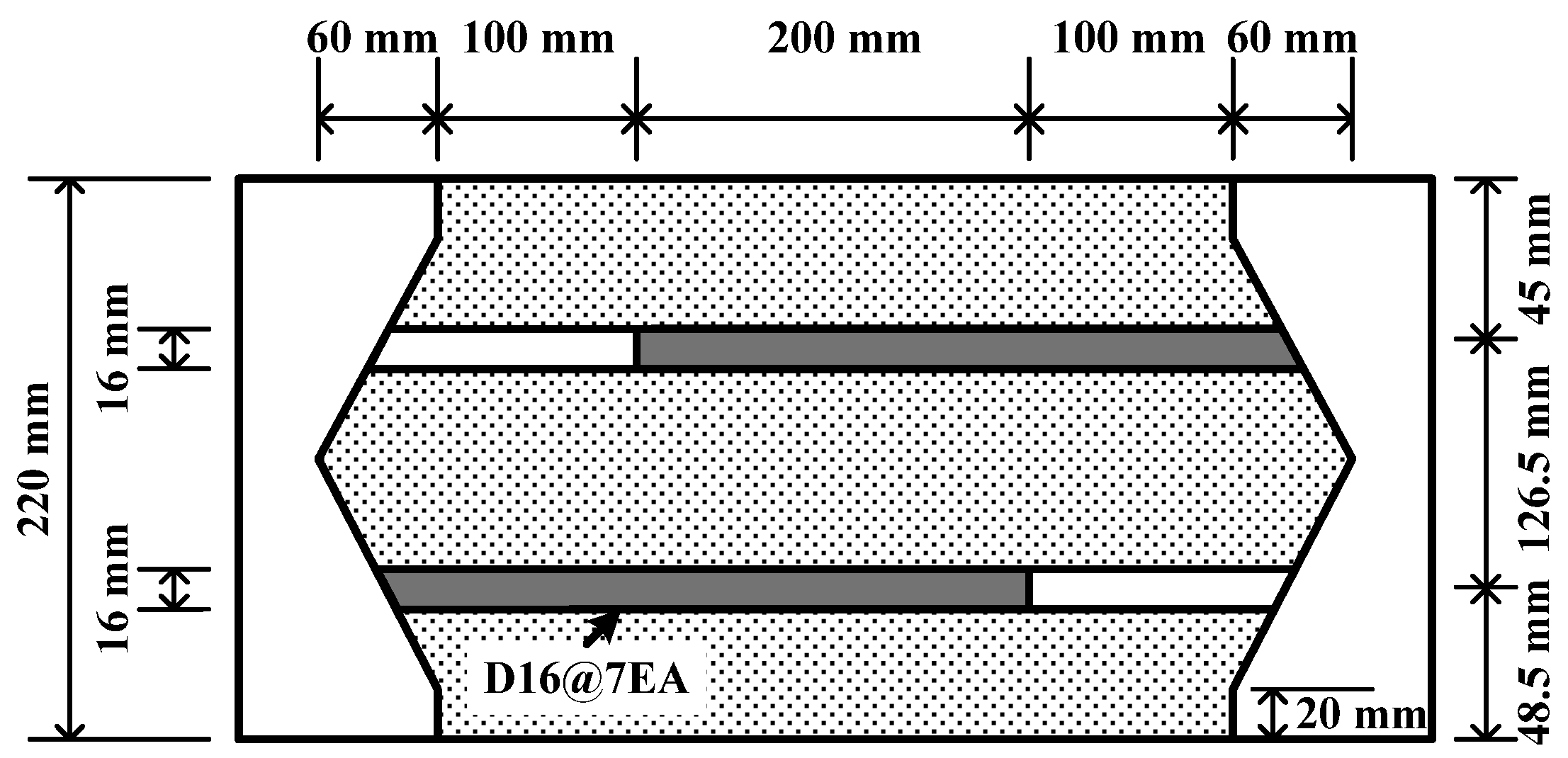
2.2.3. Reinforcement Arrangement
2.2.4. Reinforcement Development and Splice Length
3. Results and Discussion
3.1. Load and Strength
3.2. Height
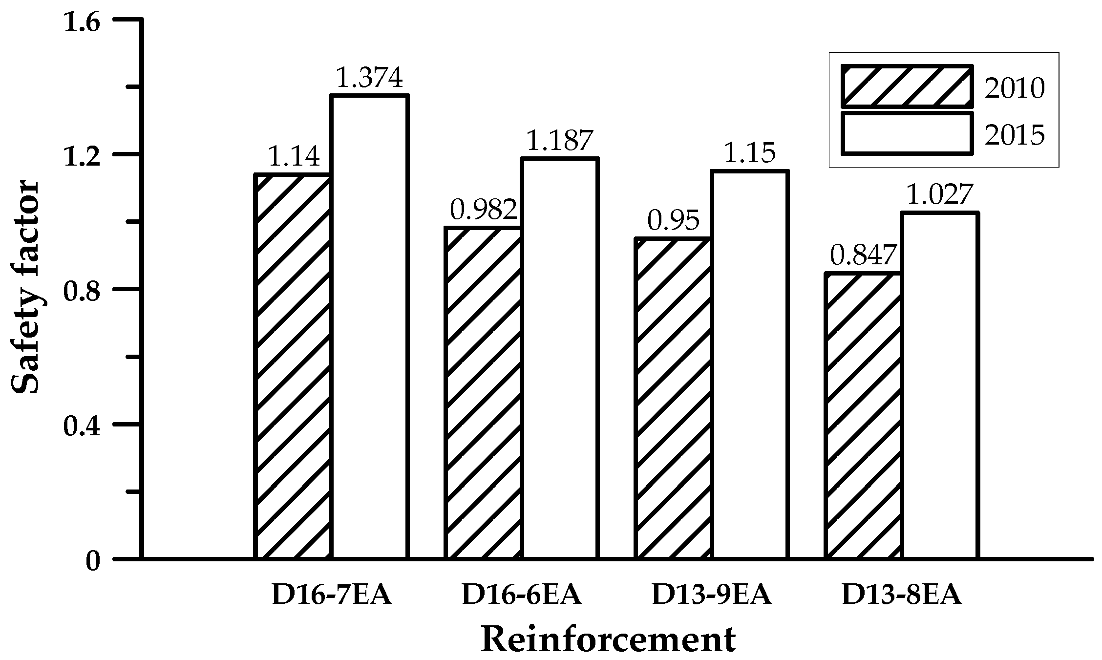
3.3. Reinforcement
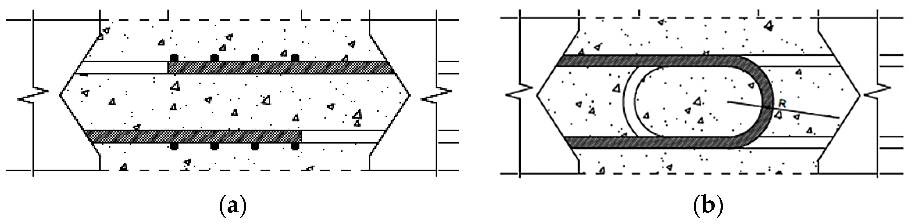
3.4. New Design of Joint
4. Conclusions
Acknowledgments
Author Contributions
Conflicts of Interest
References
- American Society of Civil Engineers. Report Card for America’s Infrastructure, 1st ed.; American Society of Civil Engineers: Reston, VA, USA, 2013; pp. 35–38. [Google Scholar]
- Culmo, M.P. Accelerated Bridge Construction Manual—Experience in Design, Fabrication and Erection of Prefabricated Bridge Elements and Systems, 1st ed.; Federal Highway Administration: McLean, VA, USA, 2011; pp. 22–68. [Google Scholar]
- Park, J.; Choi, J.; Lee, H.; Park, S.; Hong, S. Evaluation of Structural Behavior and Moment of Inertia on Modular Slabs Subjected to Cyclic Loading. J. Korea Inst. Struct. Maint. Insp. 2015, 19, 95–102. [Google Scholar] [CrossRef]
- Choi, J.; Park, S.K.; Kim, H.Y.; Hong, S. Behavior of high-performance mortar and concrete connections in precast concrete elements: Experimental investigation under static and cyclic loadings. Eng. Struct. 2015, 100, 633–644. [Google Scholar] [CrossRef]
- Li, L.; Jiang, Z. Flexural Behavior and Strut-and-tie Model of Joints with headed bar details Connecting Precast Members. Perspect. Sci. 2016, 7, 253–260. [Google Scholar] [CrossRef]
- Ryu, H.K.; Kim, Y.J.; Chang, S.P. Experimental Study on Static and Fatigue Strength of Loop Joints. Eng. Struct. 2007, 29, 145–162. [Google Scholar] [CrossRef]
- Perry, V.H.; Royce, M. Innovation field-cast UHPC joints for precast bridge decks (full-depth precast deck panels). In Proceedings of the 2010 Concrete Bridge Conference: Achieving Safe, Smart & Sustainable Bridges, Phoenix, AZ, USA, 24–26 February 2010.
- Zhu, P.; Ma, Z.J.; Cao, Q.; French, C.E. Fatigue Evaluation of Longitudinal U-Bar Joint Details for Accelerated Bridge Construction. J. Bridge Eng. 2012, 17, 191–200. [Google Scholar] [CrossRef]
- Grace, N.; Asce, M.; Ushijima, K.; Baah, P.; Bebawy, M. Flexural Behavior of a Carbon Fiber—Reinforced Polymer Prestressed Decked Bulb T-Beam Bridge System. J. Compos. Constr. 2013, 17, 497–506. [Google Scholar] [CrossRef]
- Graybeal, A.B. Behavior of Ultra-High Performance Concrete Connectons Between Precast Bridge Deck Elements. In Proceedings of the 2010 Concrete Bridge Conference: Achieving Safe, Smart & Sustainable Bridges, Phoenix, AZ, USA, 24–26 February 2010.
- Li, L.; Ma, Z.J.; Oesterle, R.G. Improved Longitudinal Joint Details in Decked Bulb Tees for Accelerated Bridge Construction: Concept Development. J. Bridge Eng. 2010, 15, 327–336. [Google Scholar] [CrossRef]
- Chapman, C.E. Behavior of Precast Bridge Deck Joints with Small Bend Diameter U-Bars. Master’s Thesis, University of Tennessee, Knoxville, TN, USA, August 2010. [Google Scholar]
- Ministry of Land, Transport and Maritime Affairs. Bridges Design Code 2010, 1st ed.; Korea Road Association: Seoul, Korea, 2010. [Google Scholar]
- American Association of State Highway and Transportaion Officials. AASHTO LRFD Bridge Design Sepcifications, 5th ed.; American Association of State Highway and Transportaion Officials: Washington, DC, USA, 2010. [Google Scholar]
- Pohang Iron and Steel Company. Research & Business Development of Modular Bridges, Final ed.; Korea Agency for Infrastructure Technology Advancement: Anyang, Korea, 2015; pp. 1–160. [Google Scholar]
- Ministry of Land, Infrastructure, and Transport. Bridges Design Code (Limit State Design), 2nd ed.; Korea Road Association: Seoul, Korea, 2014. [Google Scholar]


| Classification | Value |
|---|---|
| Standard design strength of the concrete (MPa) | 50 |
| Average compressive strength of the concrete (MPa) | 55 |
| Average tensile strength of the concrete (MPa) | 4.34 |
| Standard tensile strength of the concrete (MPa) | 3.04 |
| Elastic modulus of the concrete (MPa) | 32,902 |
| Yield strength of the reinforcement (MPa) | 400 |
| Elastic modulus of the reinforcement (MPa) | 200,000 |
| Specific weight of the concrete () | 25.0 |
| Specific weight of the pavement () | 23.0 |
| Strength of the high-strength concrete of the joint (MPa) | 120 |
| Reinforcement Type | Minimum Inner Radius (mm) |
|---|---|
| D10–D25 | 3 |
| D29–D35 | 4 |
| Over D38 | 5 |
| Reinforcement Type | Under D16 | Over D19 |
|---|---|---|
| Rounded bar | 1.25 | 2.5 |
| Deformed bar | 2 | 3.5 |
| Load Type (kN·m) | Code 2010 | Code 2015 | ||
|---|---|---|---|---|
| Factor | Load (kN·m) | Factor | Load (kN·m) | |
| Dead load | 1.30 | 1.066 | 1.50 | 1.066 |
| Live load | 2.15 | 31.272 | 1.80 | 30.070 |
| Factored load | 68.621 | 55.725 | ||
| Flexural strength | 78.207 | 76.543 | ||
| Safety factor | 1.140 | 1.374 | ||
| Height (mm) | Code 2010 | Code 2015 | ||
|---|---|---|---|---|
| Strength (kN·m) | Safety Factor | Strength (kN·m) | Safety Factor | |
| 220 | 78.207 | 1.140 | 76.543 | 1.374 |
| 215 | 75.843 | 1.105 | 74.041 | 1.329 |
| 210 | 73.480 | 1.071 | 71.538 | 1.284 |
| 205 | 71.117 | 1.036 | 69.036 | 1.239 |
| 200 | 68.753 | 1.002 | 66.534 | 1.194 |
| 195 | 66.390 | - | 64.031 | 1.149 |
| Height (mm) | Code 2010 | Code 2015 | |
|---|---|---|---|
| D16–7EA (1390.2 mm2) | D16–6EA (1191.6 mm2) | D13–9EA (1140.3 mm2) | |
| 220 | 1.140 | 1.187 | 1.150 |
| 215 | 1.105 | 1.149 | 1.113 |
| 210 | 1.071 | 1.110 | 1.076 |
| 205 | 1.036 | 1.072 | 1.039 |
| 200 | 1.002 | 1.033 | 1.002 |
| 195 | 0.967 | 0.995 | 0.966 |
| Classification (mm) | 2010 | 2015 | |||
|---|---|---|---|---|---|
| Height | 220 | 215 | 220 | ||
| Reinforcement | D16–7EA (1390.2 mm2) | D16–6EA (1191.6 mm2) | D13–9EA (1140.3 mm2) | ||
| Basic development length | 140.2 | 152.2 | 123.7 | ||
| Splice type | Lap splice | Lap splice | Loop | Lap splice | Loop |
| Splice length | 182.3 190 | 138.4 150 | 135.8 140 | 112.4 120 | 98.14 100 |
| Joint width | 380 | 300 | 280 | 240 | 200 |
© 2016 by the authors; licensee MDPI, Basel, Switzerland. This article is an open access article distributed under the terms and conditions of the Creative Commons Attribution (CC-BY) license (http://creativecommons.org/licenses/by/4.0/).
Share and Cite
Park, J.; Choi, J.; Lee, H.; Park, S.-K.; Hong, S. A Study on the Design of the Top Flange of a Modular T-Girder Bridge Using the Limit State Design Method. Appl. Sci. 2016, 6, 381. https://doi.org/10.3390/app6120381
Park J, Choi J, Lee H, Park S-K, Hong S. A Study on the Design of the Top Flange of a Modular T-Girder Bridge Using the Limit State Design Method. Applied Sciences. 2016; 6(12):381. https://doi.org/10.3390/app6120381
Chicago/Turabian StylePark, Jongho, Jinwoong Choi, Hongmyung Lee, Sun-Kyu Park, and Sungnam Hong. 2016. "A Study on the Design of the Top Flange of a Modular T-Girder Bridge Using the Limit State Design Method" Applied Sciences 6, no. 12: 381. https://doi.org/10.3390/app6120381