1. Introduction
Stavax (modified AISI 420) stainless mold steel is highly resistant to corrosion, it is also tough and wear resistant and can be polished to a high finish. A fine polished finish is a basic requirement for plastic molds because it directly affects the appearance of the product. Molds made of Stavax (modified AISI 420) are usually machined by end milling in computer numerical control (CNC) machining stations. The roughness of the finished mold surface will determine the amount of work that will be needed in the final grinding and polishing process to give the kind of smooth surface needed for a good mold. In other words, a milling process that gives the least rough surface to the steel mold surface is desirable. Polishing is an essential step in the manufacture of high-quality molds and dies. It is labor intensive, very time consuming and can account for 30%–50% of the time taken by the entire die making process [
1]. Therefore, any improvement in the surface roughness of the final machined mold will reduce the amount of labor and time needed to complete the work and also reduce cost.
There have been a number of studies made on the use of ultrasonically assisted machining aimed at improving the process. Irene et al. [
2] reported on the effect of the eccentricity, helix angle and feed on the surface roughness during side milling operations with cylindrical tools. A model was developed to predict various roughness parameters and surface topography. The roughness topography was acquired from a specific tool with eccentricity and grinding errors from distinct helix angles. Su et al. [
3] studied a hydrodynamic polishing process under semi-contact lubricating conditions used to increase the efficiency of surface irregularity reduction. Several investigations of the variations in the magnitude of workpiece surface irregularity were carried out during the fine finishing process. These experiments indicated that the magnitude and wavelength of the surface irregularities of the workpiece are related to the surface irregularity conduction. Lian et al. [
4] investigated ultrasonic vibration-assisted micromilling (UVAM) using longitudinal vibration of the workpiece. The major difference between ordinary micromilling and UVAM lies is the trajectory of the cutter tooth. A mathematical model has been developed to simulate this, and a series of experiments were performed to investigate the surface roughness of Al6061 processed by micromilling with and without ultrasonic vibration. Maurotto and Wickramarachchi [
5] investigated the effects of frequency in UVAM using axial vibration of the cutter. A set of face-milling experiments under dry conditions were carried out on AISI 316L, an alloy that is widely used in the industry. The finished surface roughness was studied along with basic consideration of frequency in UVAM (20–40–60 kHz) under a range of cutting conditions and compared with the tool wear in conventional milling. Cross sections of the metal were examined and measurements of excess surface stress were used to investigate the latent effects of UVAM. Wang and Liu [
6] investigated the cutting performances of four solid ceramic end milling tools, including Ti(C,N), Si
3N
4, LT55 and SG4 for machining hardened AISI H13 steel (HRC 60–62). The results showed that the cutting force was lower for ceramic end milling tools than for cemented carbide cutters, and ceramic tools such as Ti(C,N)-cermets, Si
3N
4, and LT55 generate better surface quality and these tools have much longer life. Kuo and Tsa [
7] suggested that the simplest and most effective way to improve the machining efficiency of ultrasonic milling was to first improve the design of the tool. The main purpose of the study was to make use of rotary ultrasonically assisted machining (RUM) on brittle material, investigate the application of milling on brittle materials and innovative manufacturing methods such as automated rotary ultrasonic machining. In addition, RUM is used for other brittle materials such as glass [
8], potassium dihydrogen phosphate (KDP) [
9], composite materials [
10,
11], ceramics [
12], and sapphire [
13].
The roughness of a milled surface depends not only on the sharpness and condition of the milling cutter teeth, the feed rate and the size of the cut, but also to a large part on cutter aspect geometry. In this paper, we present the findings of an experimental investigation of the roughness of the surface on Stavax (modified AISI 420) stainless mold steel achieved by ultrasonic-assisted end milling. The effects of the stretch length of the cutter, the cutter holding force and the input voltage on the ultrasonic vibration amplitude were all measured. The effects of frequency (25 and 50 kHz) and amplitude (0, 2.20 and 3.68 µm) of the ultrasonic vibrations as well as the effects of the rake angle (6° and −6°) and helix angle (25°, 35° and 45°) of the cutter on both tool wear and mold surface finish quality were investigated.
2. Experimental
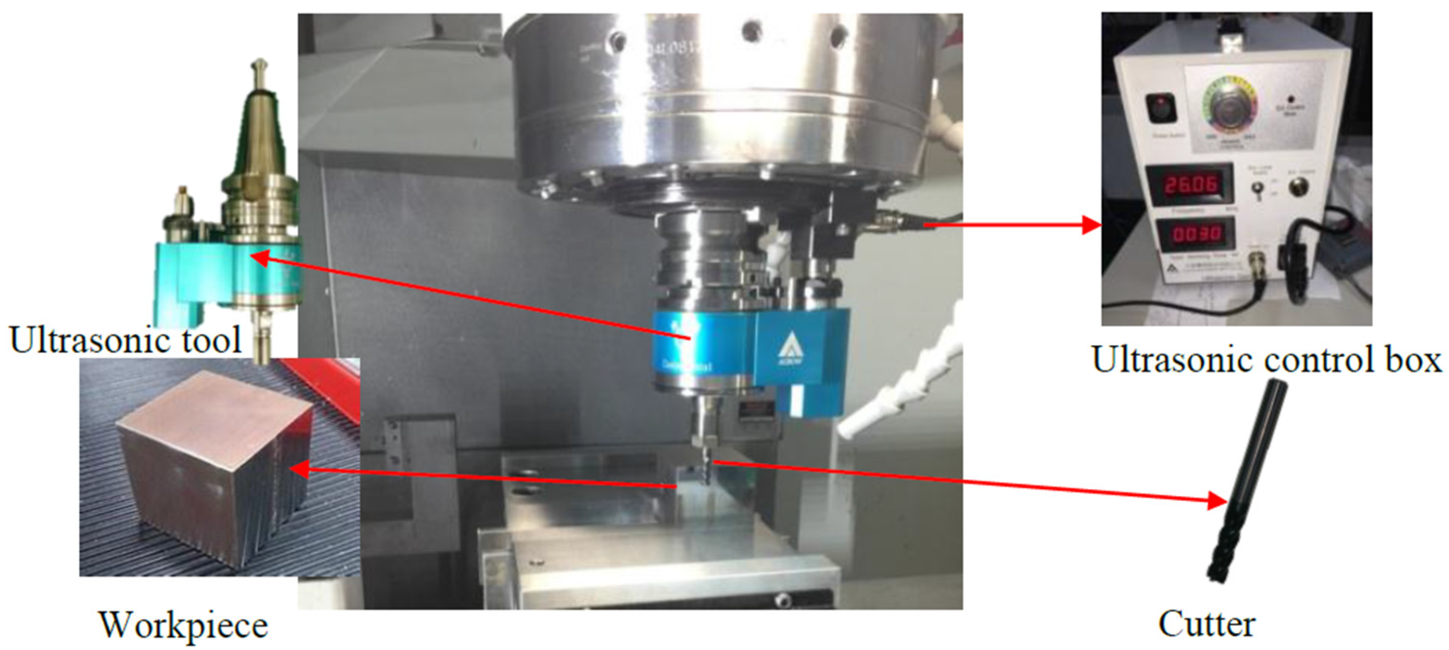
In this study, a VMP-40A three-axis vertical machining center, manufactured by the Feeler Machine Tool Company (Taichung, Taiwan) with a maximum spindle speed of 10,000 rpm was used. The milling platform consists of several individual systems such as the feed, drive control, ultrasonic generator and transducer, and the machine tool head, as shown in
Figure 1. The feed screws of the three separate machine axes were controlled by stepper motors under the command of a CNC computer program, eliminating the human factor completely. The high frequency feed from the ultrasonic generator unit caused ultrasonic vibration of the piezoelectric transducer (PZT) in the machine head tool-holder assembly which in turn caused the milling cutter to vibrate along its vertical axis. The ultrasonic generator allowed control of both the frequency and power of the signal. The amplitude of the ultrasonic vibration applied to the milling cutter was adjustable between 2 and 10 μm, and this was measured using a Keyence LK-H008Wlaser displacement instrument (Osaka, Japan) which has a repeatability precision of 0.005 μm.
Cemented carbide flat-end milling cutters 6 mm in diameter with 2 teeth were used and cutters with helix angles of 25°, 35° and 45° were employed at rake angles of both −6° and 6°. All the workpieces used in this study were Stavax (modified AISI 420) mold steel blocks 50 × 50 × 50 mm. The milling parameters were set at: depth of cut 100 µm, spindle speed 6000 rpm, feed rate 100 mm/min. The main machining parameters for the current study are listed in
Table 1. The surface roughness of the workpiece was determined by non-contact three-dimensional (3D) white light interferometry using a Zygo New View 8300 interferometer (AMETEK, Ltd., New York, NY, USA) which has an RMS repeatability of 0.01 nm and a measuring range of up to 20 mm. The tool wear was measured using a Keyence HX-5000 optical microscope (Osaka, Japan) which has
X- and
Y-axis resolution of 1 μm and a
Z-axis resolution of 0.1 μm.
3. Results and Discussion
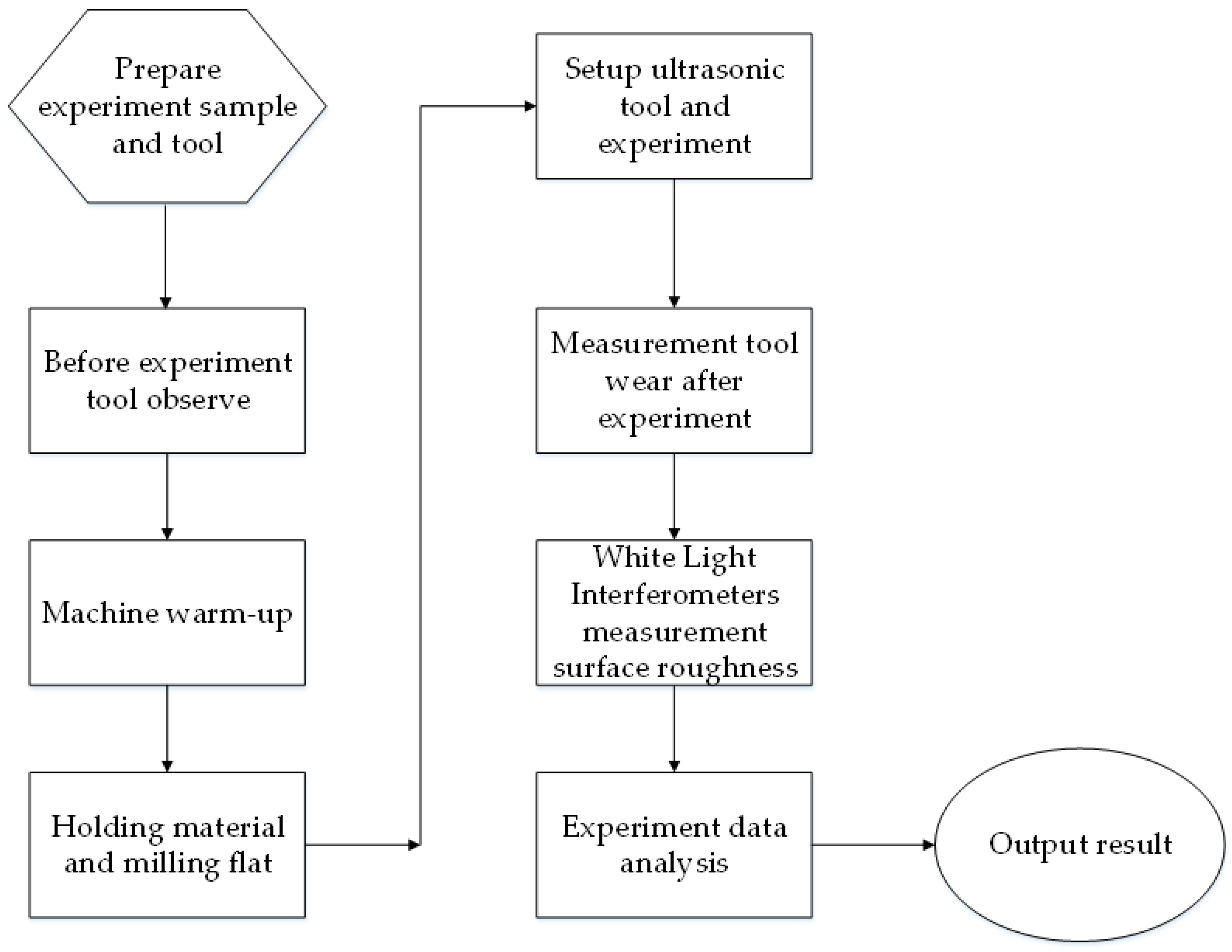
Figure 2 shows the detailed procedure flow chart, each experiment was repeated three times to ensure reproducibility.
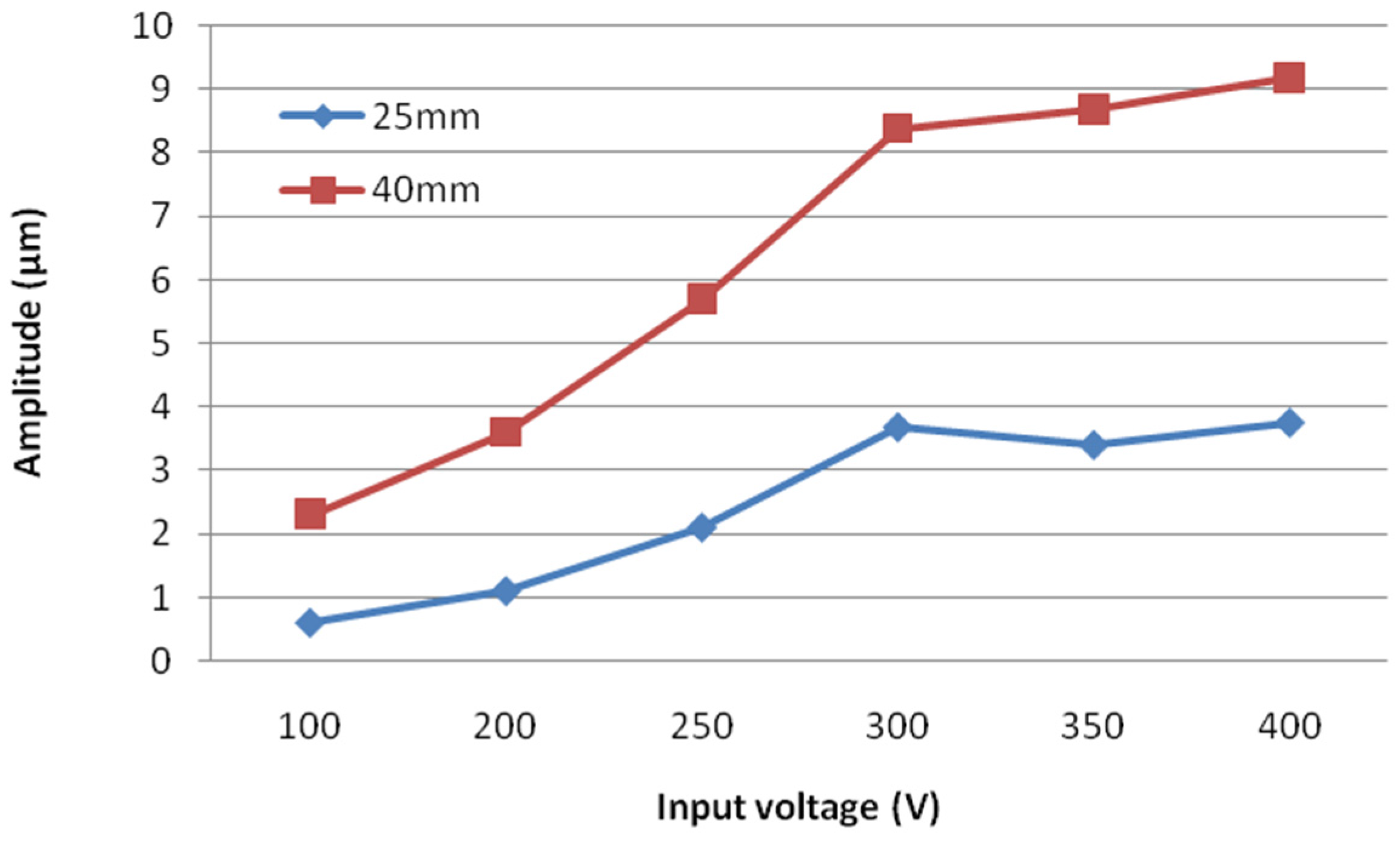
Figure 3 shows the variation in amplitude with input voltage for different stretch lengths of the cutter (25 and 40 mm). The amplitude for the stretch length of 40 mm increased with input voltage from 2.1 μm at 100 V to 9.2 μm at 450 V. In addition, the amplitude for the stretch length of 25 mm increased with input voltage from 0.6 μm at 100 V to 3.7 μm at 450 V. It was found that the amplitude of the ultrasonic displacement increased with increasing stretch length and input voltage. Although increasing the stretch length of the cutter can increase the amplitude, it leads to less rigidity.
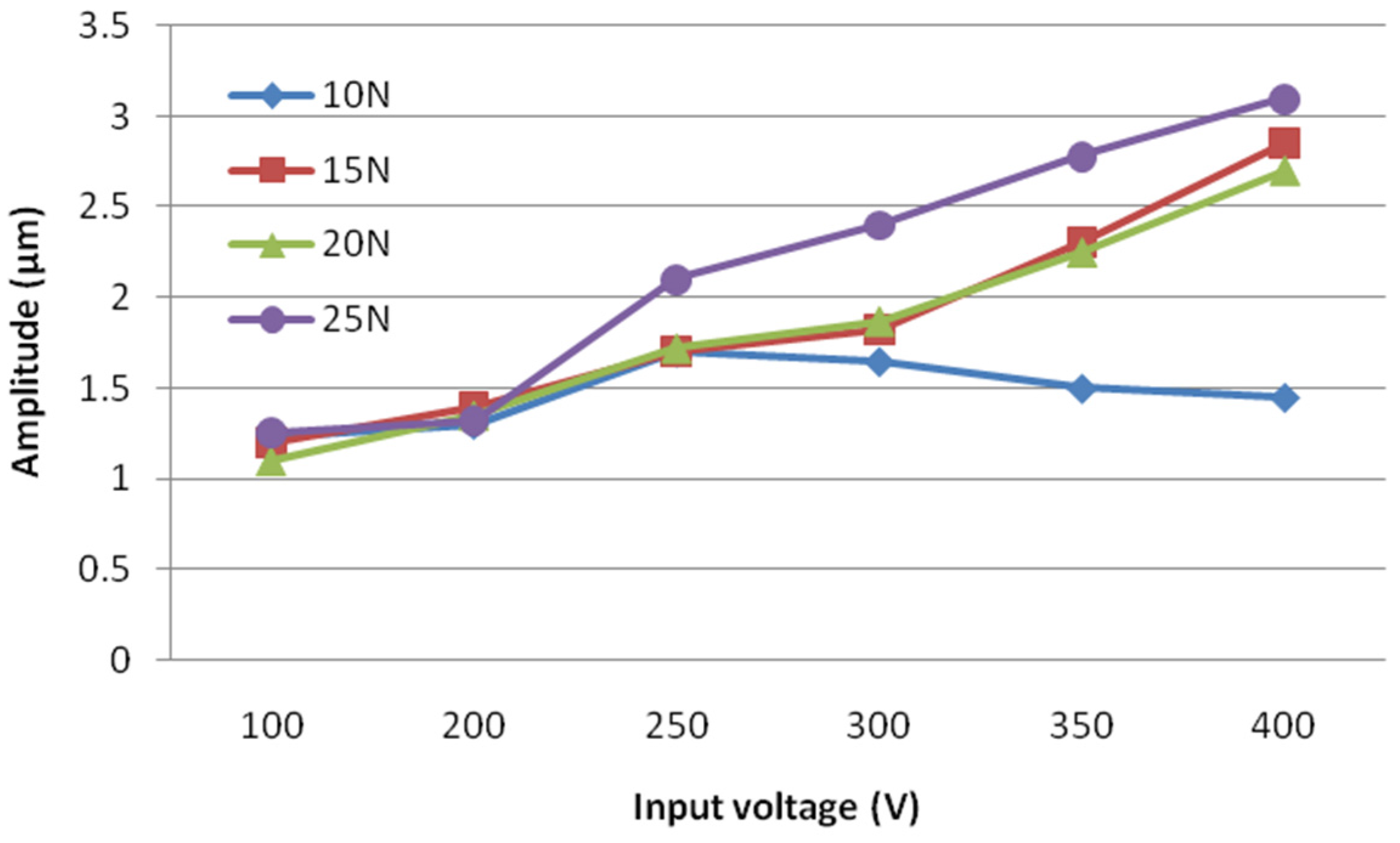
Figure 4 also shows the variation in the amplitude with input voltage for different cutter holding force (10, 15, 20 and 25 N). The amplitude increases with an increase in the input voltage for the holding force of 15, 20 and 25 N. However, for a holding force of 10 N, the amplitude increased with the input voltage up to 250 V, and was then reduced with further increase in voltage. A holding force of 15 N or more is recommended because the amplitude will then remain constant.
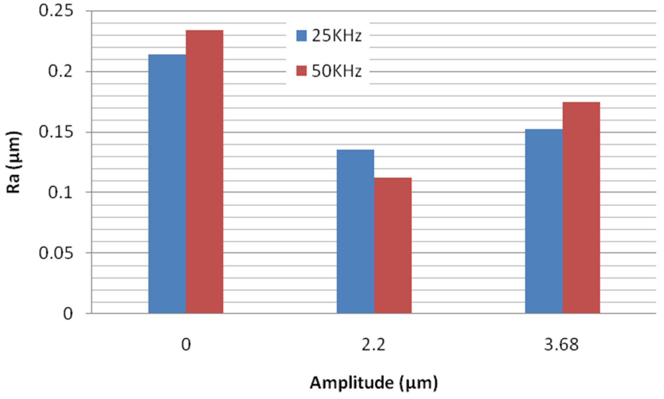
Figure 5 shows the variation in surface roughness (
Ra) of the workpiece for unassisted milling and ultrasonic-assisted milling (amplitude of 2.20 and 3.68 μm) at two different frequencies (20 and 50 kHz). The purpose of the experiment was an evaluation of the effect of ultrasonically assisted milling and whether it improved the roughness of the machined surface or not. Three samples were processed using the same machining parameters, and the surface roughness was assessed as an average of the roughness of the three. For unassisted milling, the
Ra value was approximately 0.236 μm. For assisted milling at an ultrasonic amplitude of 2.20 µm, the
Ra values were 0.136 and 0.110 μm at 20 and 50 kHz, respectively. At an amplitude of 3.68 µm,
Ra values were 0.151 and 0.174 µm at 20 and 50 kHz, respectively. It is clear from these
Ra figures that a better finish can be achieved with ultrasonic-assisted milling. It also became clear that there is an optimal value for the amplitude of the ultrasonic vibration used which will give the best finish under the conditions of these experiments. This is believed to be a result of the “hammer effect” induced by ultrasonic vibration. Because of the high-frequency vibration, the cutter teeth will hammer the workpiece constantly. This means the quality of the processed surface can be improved by the choice of an appropriate ultrasonic amplitude. Simply raising the amplitude does not work because the ideal amplitude depends on other cutting conditions such a feed, depth of cut and so on. This finding agrees with that of Lian et al. [
4].
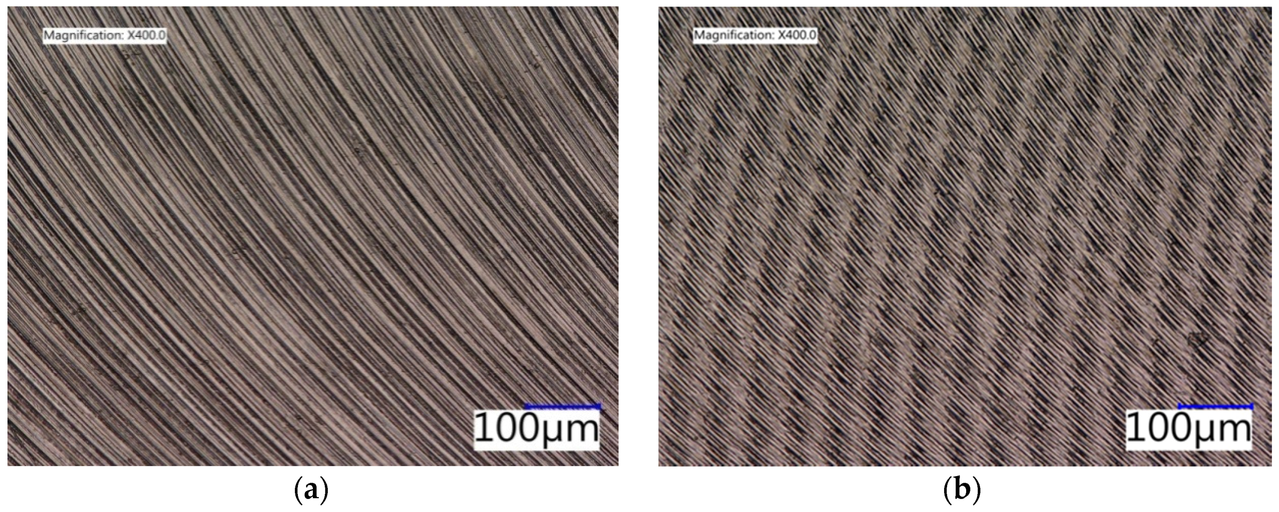
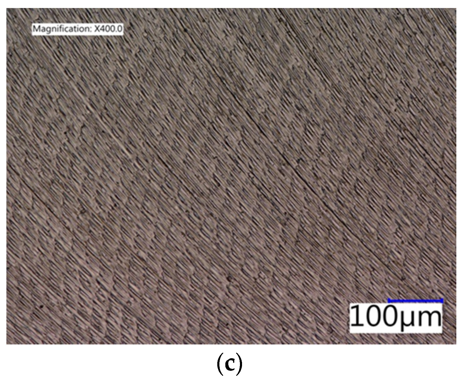
Figure 6 shows optical micrographs (400×) of the surface of a sample machined by unassisted milling, compared to that of samples milled with ultrasonic assistance at frequencies of 20 and 50 kHz. In
Figure 6a there are prominent machining marks on the Stavax (modified AISI 420) sample surface. In
Figure 6b,c the machining marks are less evident and there are dark lines present associated with ultrasonic assistance. The surfaces were also much finer and more uniform than that processed by unassisted milling.
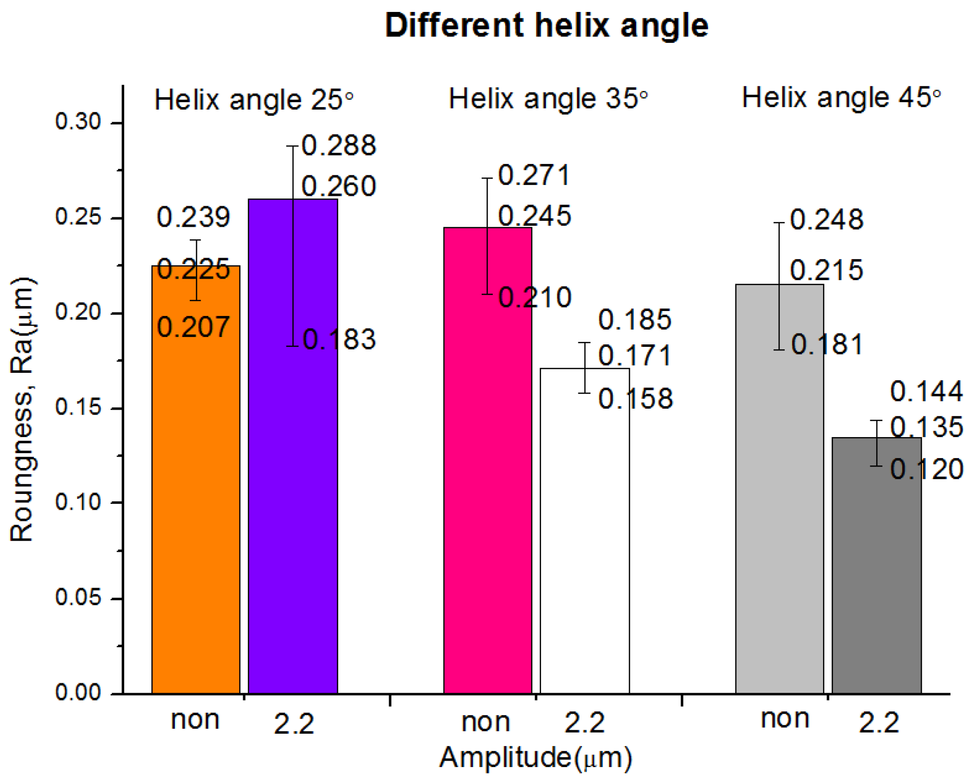
The helix angle of the tool is the angle formed between a tangent to the helix and the tool axial center line. If the flutes were straight, the whole tooth, up to the depth of the cut, would contact the material at the same time. The forces involved would be greater and there would be more vibration. The helix allows the tooth to make gradual contact with the material and softens the impact between the cutter and the material giving a smoother finish. The helix also helps move chips up and out of the cutting zone and a 45° helix generates an excellent surface finish. The bar chart in
Figure 6 shows variations in the average surface roughness (
Ra) of Stavax (modified AISI 420) samples, machined with and without ultrasonic vibration, using cutters with helix angle of 25°, 35° and 45°, all other experimental parameters remaining identical. Each experiment was repeated three times to ensure reproducibility. It can be seen from the figure that the surface roughness remains better for ultrasonic-assisted milling. The
Ra for helix angles of 25°, 35° and 45° were 0.181, 0.170 and 0.135 μm, respectively. The best
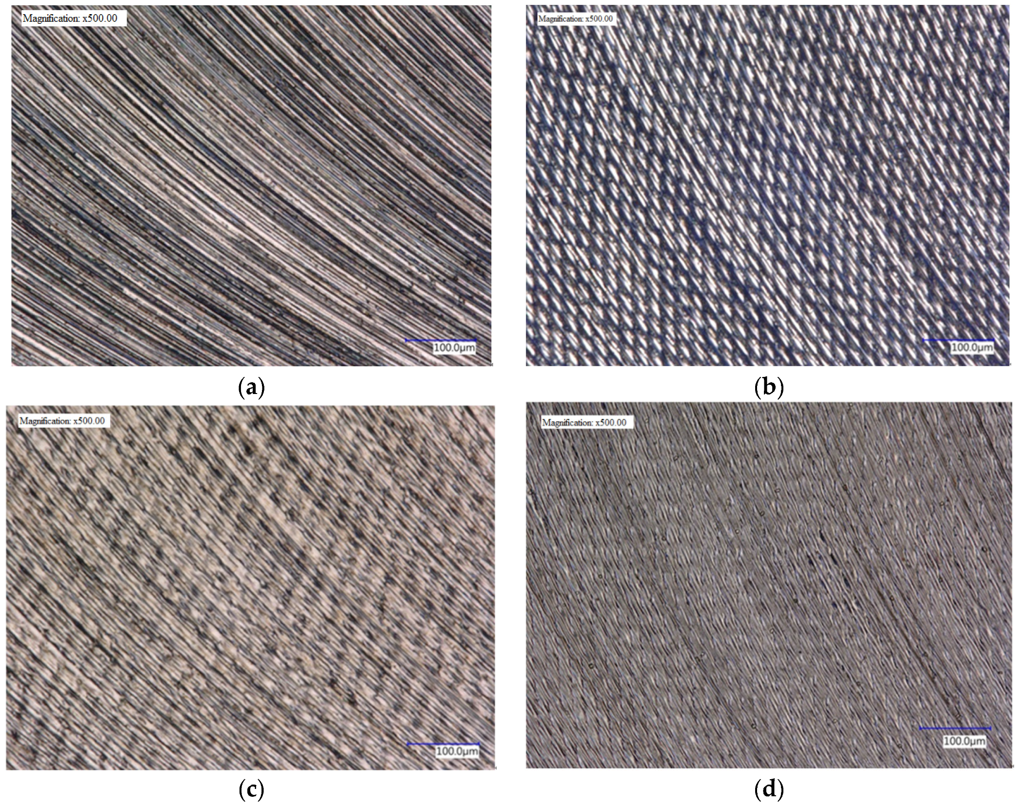
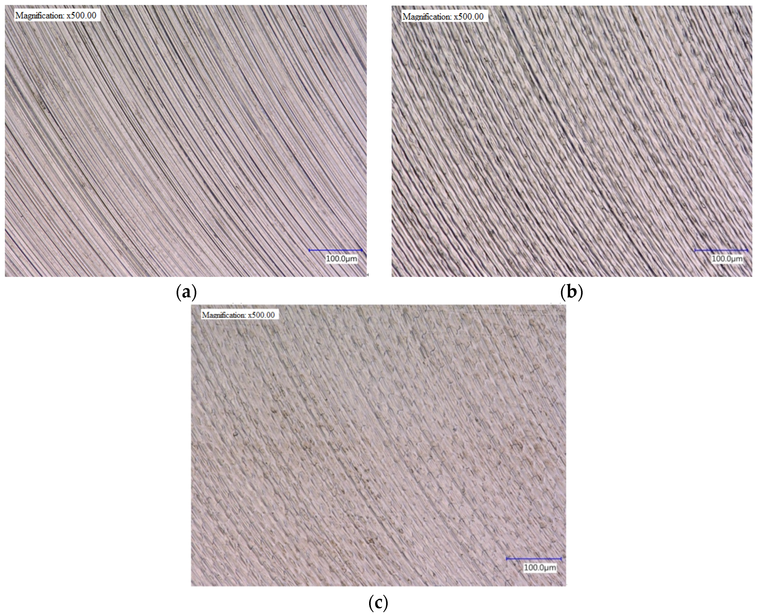
Ra was obtained using a cutter with a 45° helix. The optical micrographs (500×) in
Figure 7 show the milled surfaces of the Stavax (modified AISI 420) samples machined with and without ultrasonic assistance using cutters of different helix angle. Quite prominent cutter feed lines can be seen on the conventionally milled surface, see
Figure 8a, while the surfaces machined using ultrasonic assistance have much less obvious lines. The surface shows micro-chipping which is characteristic of ultrasonic vibration and is caused by the high frequency hammering, see
Figure 8b–d.
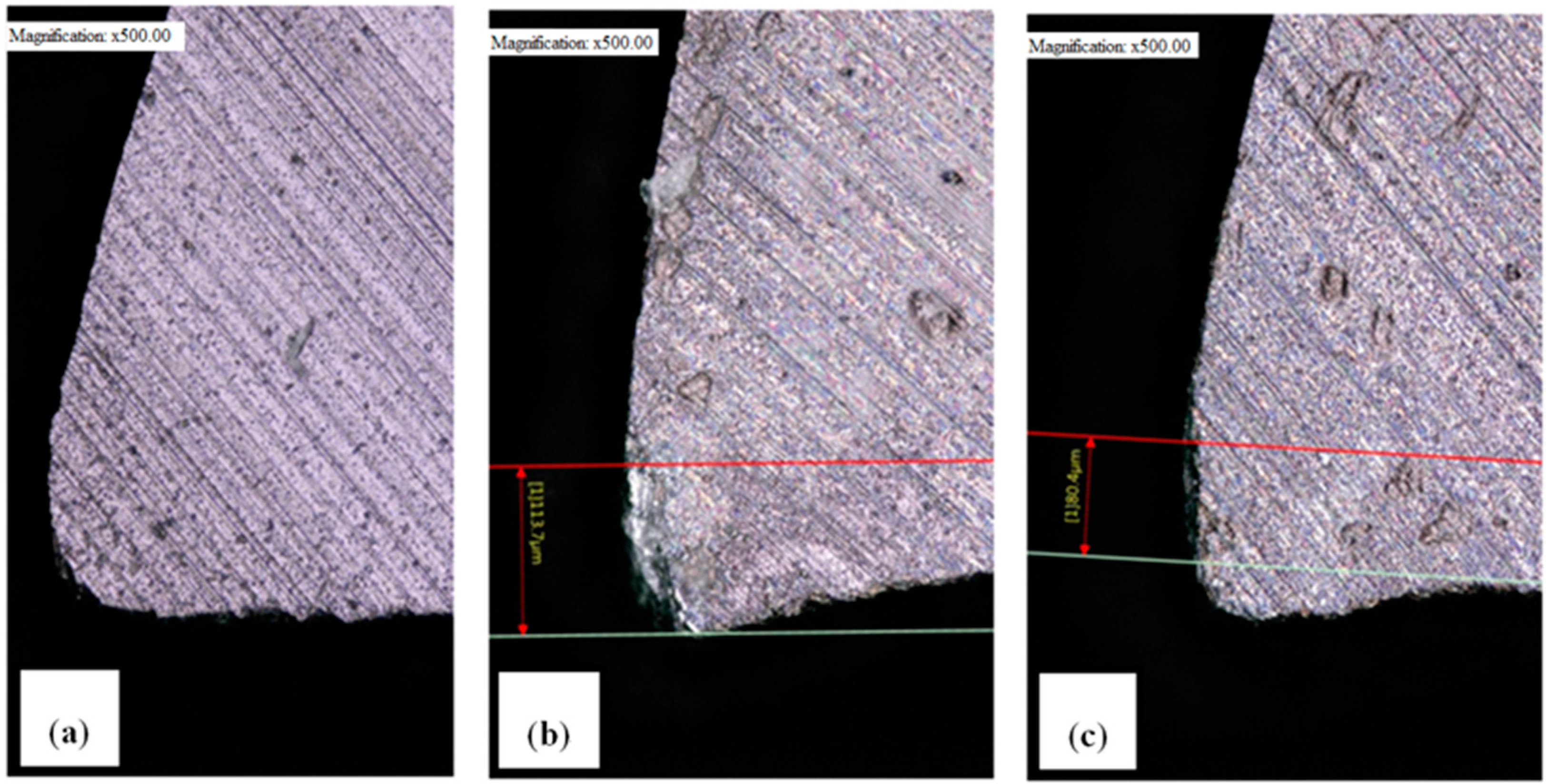
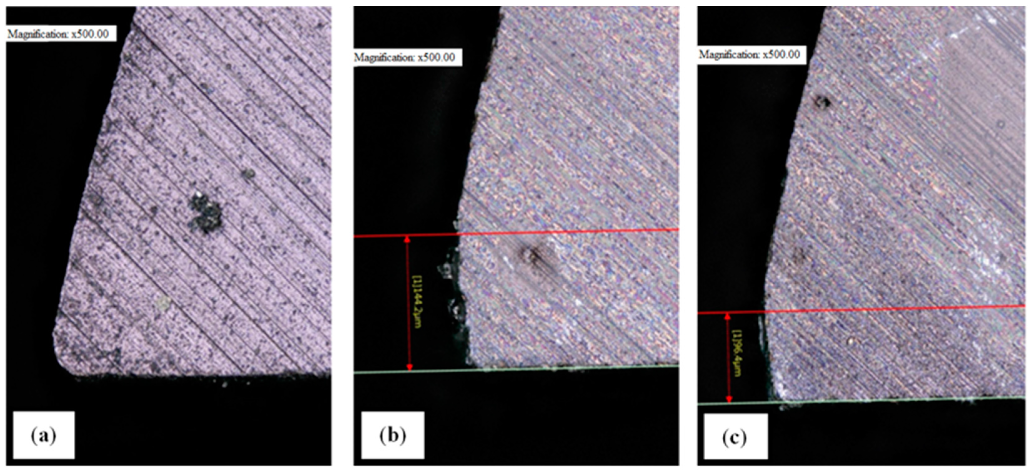
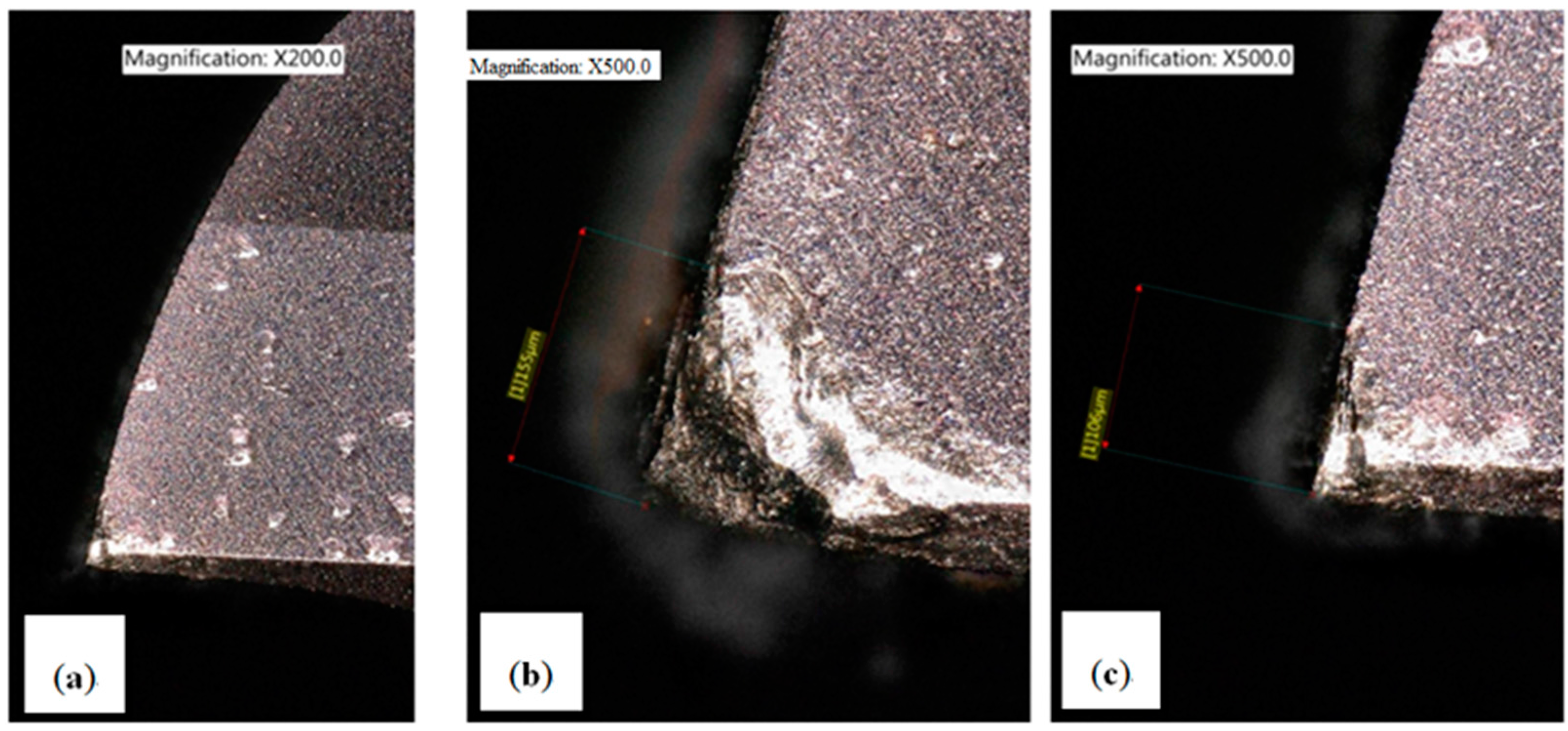
Tool wear is a most important parameter that must be taken into account with respect to the accuracy of a machined component. Accuracy is also reflected by the degree to which the machined surface corresponds to that of the cutting tool with which it was in contact during the process. Optical micrographs of the cutting edges of tools with helix angles of 25°, 35° and 45°, used with and without ultrasonics, are shown in
Figure 9,
Figure 10 and
Figure 11. It was found that tool wear with ultrasonic vibration was less than in conventional milling due to the axial movement of the cutter which periodically increases the gap between the tool and the workpiece which promotes interfacial lubrication. This is similar to the findings of Manjot et al. [
14] and Geng et al. [
15]. The conclusion is that tools used in ultrasonic-assisted machining last longer.
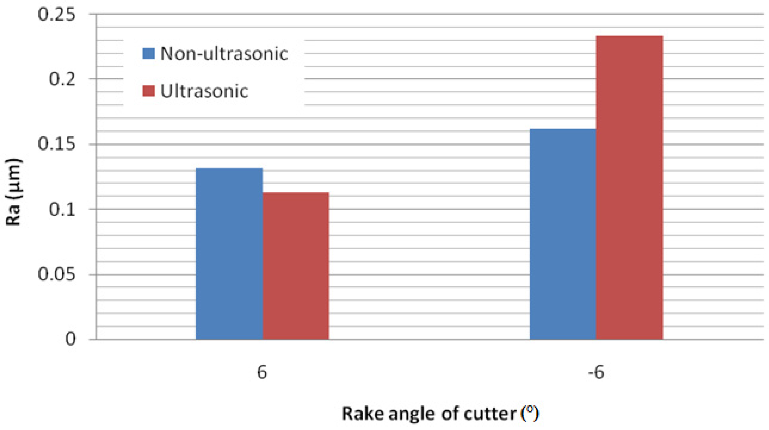
The rake angle controls two important variables, the direction of chip flow and the strength of the force on the tool tip. A positive rake angle, which leads with the cutting edge, will improve the cutting operation by reducing both force and temperature. However, a positive rake angle also exposes the cutting edge to more force over a smaller area and this can lead to chipping and tool failure. A negative rake angle, which leads with the rake surface, makes the tool effectively blunter but the cutting force is distributed over a larger area and more slowly. The effect is to make the tool stronger by reducing the force on the cutting edge. However, the cutting force is higher, as is friction, which raises the temperature. The effect of rake angle of the cutter on the surface roughness of the workpiece was also investigated and the result is shown in
Figure 12. As can be seen from the figure, the
Ra resulting from the use of a positive rake angle is better than that of a negative rake angle with or without ultrasonic assistance. However, it is interesting to notice that for a negative rake angle the
Ra achieved by unassisted milling is better than that reached with ultrasonics. Photomicrographs of the workpiece surfaces are shown in
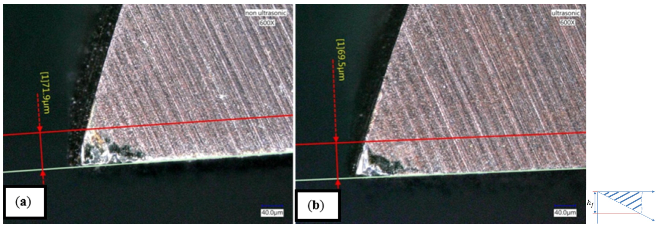
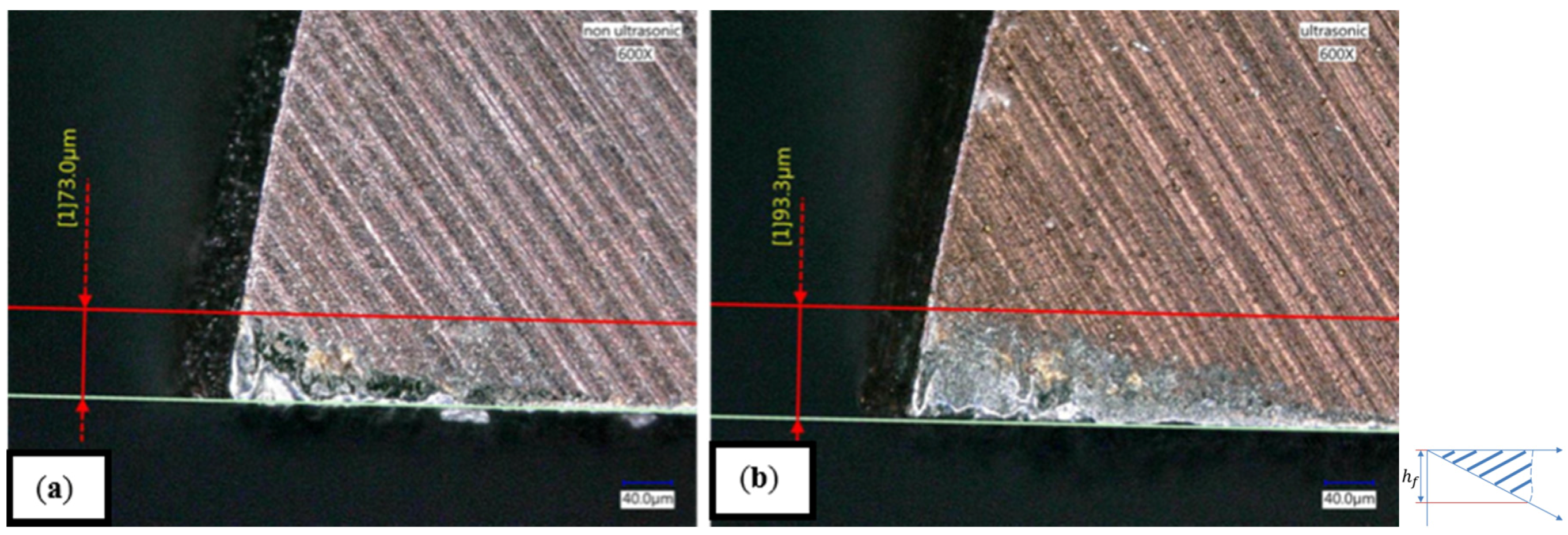
Figure 13 where it is obvious that for a rake angle of −6° the surface quality achieved without ultrasonic assistance is better than that with assistance. This should be taken into account when using ultrasonic-assisted milling. In addition, the optical micrographs in
Figure 14 and
Figure 15 shows that tool wear is also affected by rake angle and wear with ultrasonic vibration is lower than with unassisted milling, flank wear characterized by wear land (or Height) h
f of wear band. This is in agreement with the finds of Liu et al. [
16] who pointed out that ultrasonic-assisted milling removes heat more effectively and this reduces wear and prolongs tool life. Tsai et al. [
17,
18] focused on single crystal silicon carbide and cubic boron nitride (CBN) composites impregnated with micro graphite materials, and also discussion there reaction and wear behaviors. Suárez et al. [
19] investigates the effects of ultrasonic vibration-assisted milling on important aspects such us material surface integrity, tool wear, cutting forces and fatigue resistance. Celaya et al. [
20] investigated focusing on the effect of tool vibration on surface quality, and also propose a new booster design based on the theory of longitudinal vibration of a bar with varying cross-sectional area for a higher amplification of the ultrasonic vibration.
4. Conclusions
The aim of this investigation was the improvement of the surface roughness of the machined surface of Stavax (modified AISI 420) mold steel by the use of ultrasonic-assisted end milling. The effect of the stretch length, cutter holding force and input voltage on the amplitude of the ultrasonic vibrations were measured. In addition, the effect of the frequency and amplitude of the ultrasonics as well as the effect of the rake angle and cutter helix angle on the quality of the workpiece surface, as well as tool wear, were also investigated. The following conclusions were reached:
(1) The amplitude of the ultrasonic vibrations increased with cutter stretch length as well as input voltage. When the cutter holding force was more than 15 N, the amplitude remained constant and so 15 N was used to hold the cutter and is recommended.
(2) The amplitude of the ultrasonic vibrations used has an optimum value that gives the best surface finish. The quality of the processed surface can be improved if the optimum is used. Increasing the amplitude does not necessarily improve the results and can have the opposite effect.
(3) Examination of the machined surface of workpieces milled with ultrasonic assistance shows better uniformity and smoothness than is achievable with unassisted machining under the same conditions. The cutters wear more slowly in ultrasonic-assisted milling and tool life is extended.
(4) A positive rake angle with cutters that have a large helix angle (45°) using ultrasonic-assisted milling was found to give a better surface finish. The surface of the workpieces machined by ultrasonic-assisted milling, using a negative rake angle of −6°, was inferior to that achieved by unassisted milling. It should be noted that the tool response to ultrasonic vibration and the results obtained were dependent on the geometry and type of the cutters used in our experiments. Different types of cutters may give very different results.


