
Longitudinal Jitter Analysis of a Linear Accelerator Electron Gun

1
Institute of High Energy Physics, Chinese Academy of Sciences, Beijing 100049, China
2
Centre for High Energy Physics, University of the Punjab, Lahore 45590, Pakistan
*
Author to whom correspondence should be addressed.
Appl. Sci. 2016, 6(11), 350; https://doi.org/10.3390/app6110350
Submission received: 19 June 2016
/
Revised: 24 October 2016
/
Accepted: 8 November 2016
/
Published: 19 November 2016
Abstract
:We present measurements and analysis of the longitudinal timing jitter of a Beijing Electron Positron Collider (BEPCII) linear accelerator electron gun. We simulated the longitudinal jitter effect of the gun using PARMELA to evaluate beam performance, including: beam profile, average energy, energy spread, and XY emittances. The maximum percentage difference of the beam parameters is calculated to be 100%, 13.27%, 42.24% and 65.01%, 86.81%, respectively. Due to this, the bunching efficiency is reduced to 54%. However, the longitudinal phase difference of the reference particle was 9.89°. The simulation results are in agreement with tests and are helpful to optimize the beam parameters by tuning the trigger timing of the gun during the bunching process.
1. Introduction
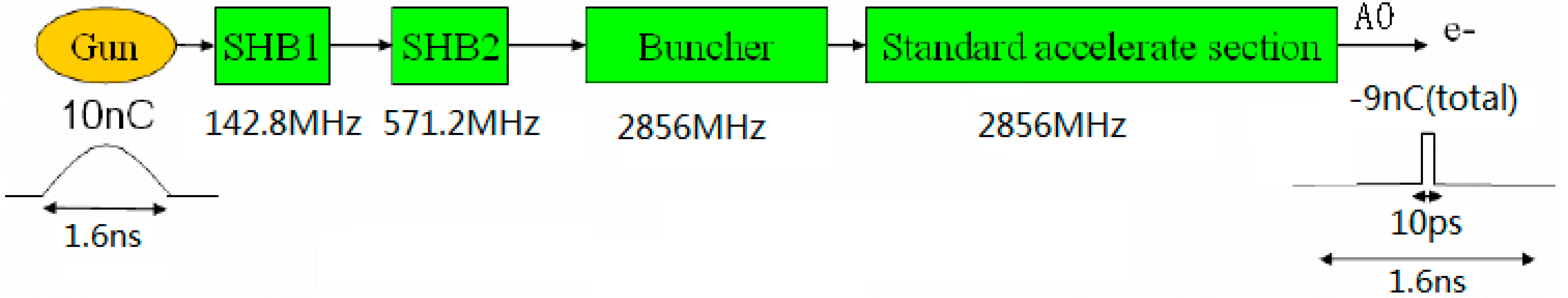
Electron gun longitudinal timing jitter can hinder not only electron beam performance but also positron yield in a routine operation of a Beijing Electron Positron Collider (BEPCII) Linac. This has been observed pragmatically many times during operation. The fact that the jitter of the gun in the transverse direction is caused by gun high voltage has already been reported elsewhere [1]. The present study is about beam bunching performance caused by the jitter of gun timing in the longitudinal direction. This trigger is influenced by many factors including the characteristics of the electronic components and variations in the environmental temperature. The threshold value for the electron gun longitudinal jitter is less than 50 ps to ensure the expected bunching results in the pre-injector [2]. The sub-harmonic bunching (SHB) system of BEPCII Linac pre-injector is composed of: an electron gun, two sub-harmonic bunchers (SHB1 and SHB2), one 4-cell travelling wave buncher and a standard 3-m long accelerating structure [3,4], as shown in Figure 1.
The electron gun [5], is powered by a high voltage power supply and triggered by signal from timing system. SHBs are derived by independent power supplies with 142.8 MHz and 571.2 MHz microwave signals. Regarding the buncher and the A0 accelerator (the microwave of which comes from the 1st klystron), any perturbation of power and phase of its exporting microwave also give some variation in beam bunching. In another sense, timing stabilization between bunch cells in a pre-injector is vital; any variation of them can cause a longitudinal jitter. The beam pulse width at the gun exit was 1 ns FWHM with 1.6 ns bottom width. After velocity modulation by SHB1 and SHB2, the beam length was ~900 ps and 500 ps at the exits without any real acceleration while it was ~60 ps and ~10 ps at the buncher and the A0 exit, respectively. Beam energy was about 50 MeV [4,6,7], which was measured by an analysis magnet installed at an A0 accelerator exit [8]. During the bunching process, any variation in longitudinal sequence between pre-injector cells is called longitudinal jitter and it may deteriorate beam performance to some extent.
2. Longitudinal Jitter Measurements
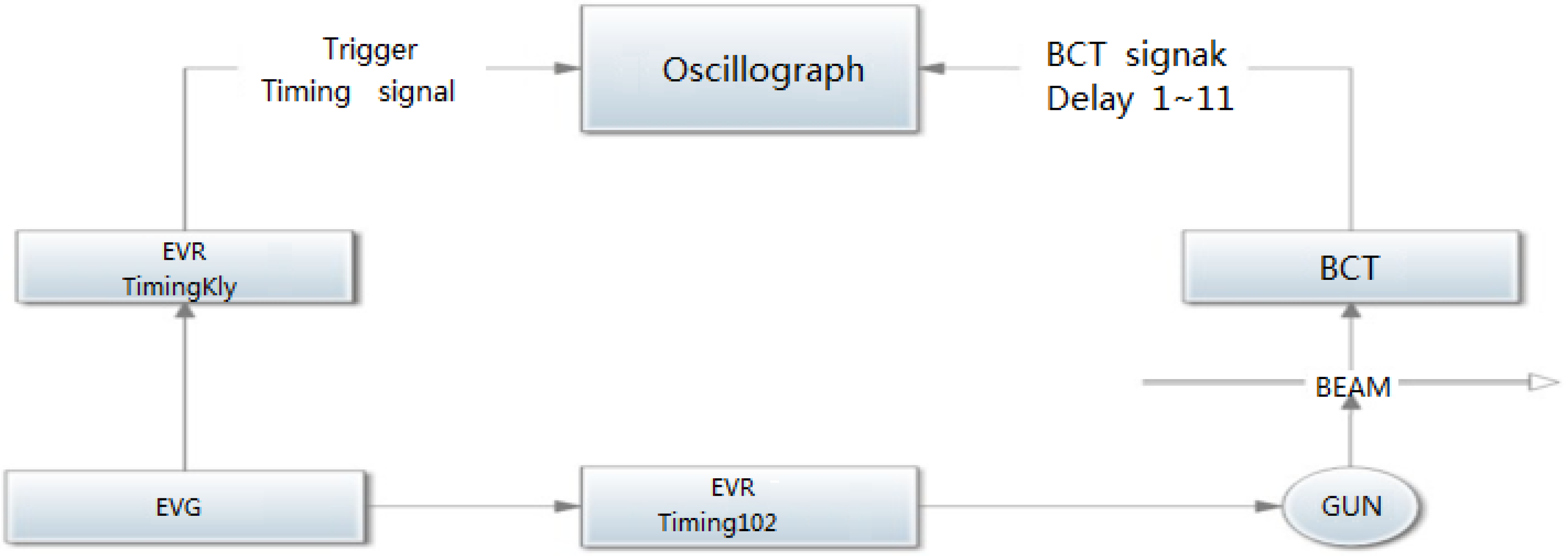
After emission from the gun, electrons were bunched by SHB1, SHB2 and the buncher. The current at the exit of the gun and A0 accelerator was measured by two Beam Current Transformers (BCTs); 1st BCT and 2nd BCT, which were displayed on oscilloscope at the control room. Therefore, we could measure the beam current and the interval between the produced bunches. Figure 2 is a schematic diagram of the beam current and timing measurement scheme in the pre-injector.
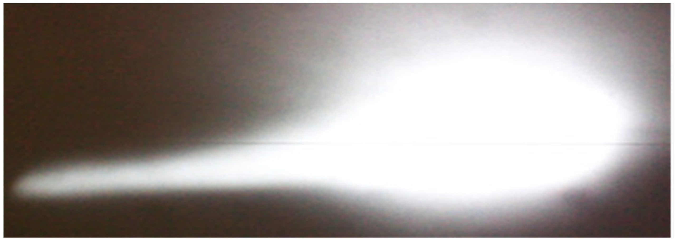
EVG and EVR are event generator and event receiver of timing system when a single beam was bunched and measured by a 6 G bandwidth oscilloscope as displayed in Figure 3. The measurement system could measure a bunch length of ~10 ps level [9]. The spot on the profile monitor produced by the analysis magnet was captured, as shown in Figure 4. The profile is taken under conditions at a single beam with 10 ps beam width (which is the best bunching efficiency). Then the time interval between BCT1 and BCT2 was observed and measured in Figure 5, which was about 21.5 ns with tolerance less than 100 ps. The calibration ratio of BCT1 was 10.95, while BCT2 was 9.87. The signal pulse height of the BCT1 was less than that of the BCT2 in the measurement with an oscilloscope, but their actual beam currents were about 10 A and 9 A, respectively, therefore, the beam bunch efficiency was about 90% [10].
If instability exists in the pre-injector cells due to gun trigger timing jitter [11], the injection phases of the beam to the SHBs are not suitable, and the signal pulse height of the BCT2 is substantially decreased compared to the normal situation. Figure 6 is one of the jitter situations which describes BCT1 and BCT2 as unstable. The BCT1 timing jitter is ~20 ps, and the timing jitter in the BCT2 is ~10 ps. Meanwhile, beam injection rate is decreased or fluctuates.
3. Results and Discussions
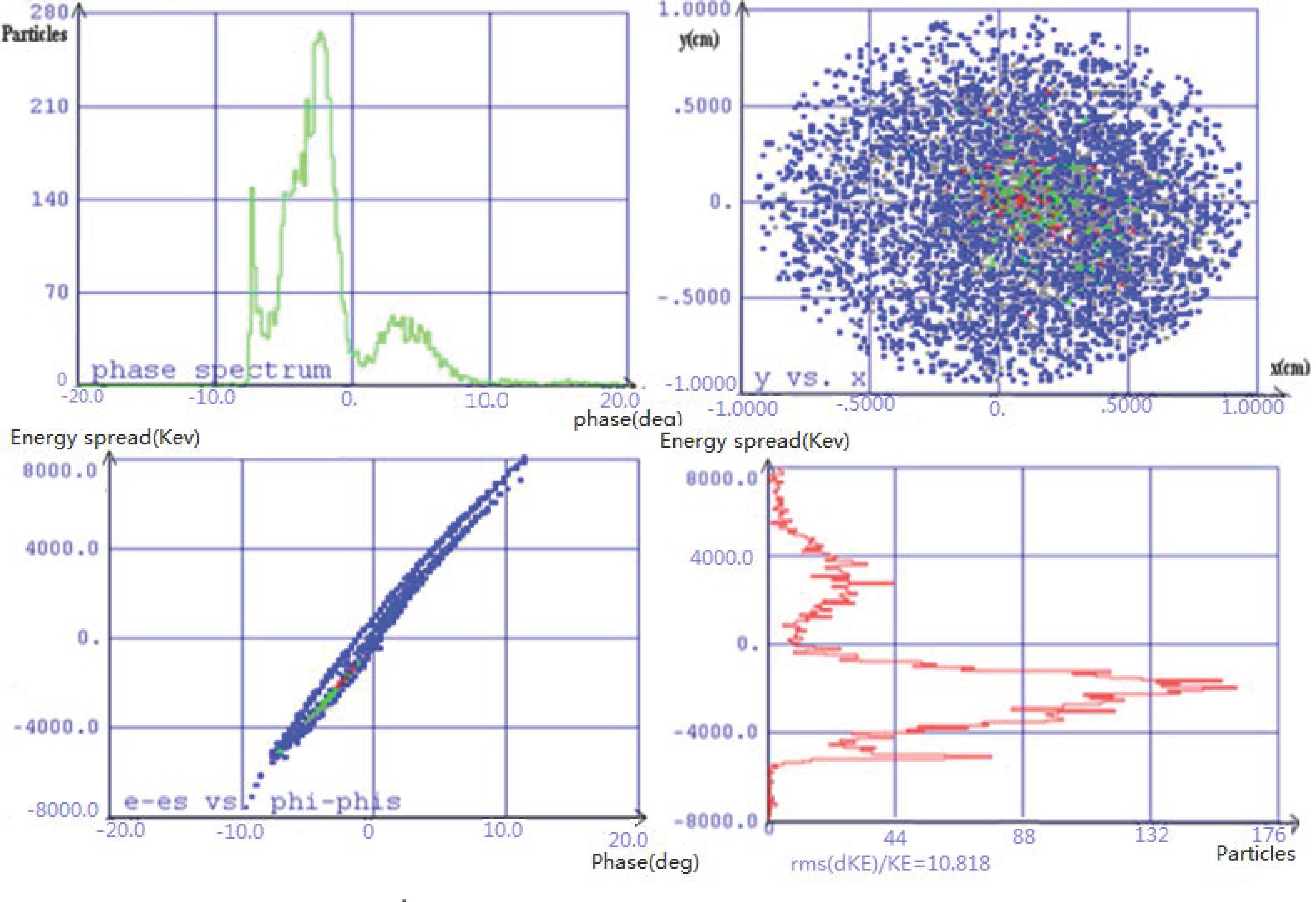
To study bunching process in pre-injector caused by gun timing jitter in longitudinal direction, simulation was done by PARMELA software [12] at 136.8 keV pulsed beam by adjusting electron trigger timing without changing other parameters. To reach maximum total energy and stable beam at the linac exit, the energy spread has to be less than ±0.5% and the emittance 0.1 mm mrad [6]. These parameters are affected the most by the bunching process, and therefore are studied in detail. In the beginning, gun trigger timing had no longitudinal jitter then beam parameters at A0 exit were calculated, as shown in Figure 7, which is composed of beam phase spectrum, beam profile, phase spread vs. energy spread and energy spectrum.
The values of transverse section, average energy, energy spread, phase of the reference particle and normalized XY emittances were 1.9 cm × 2 cm, 47.56 MeV 10.30%, 118.15° and 98.12, 98.76 mm mrad (3δ), respectively. To compare simulation results, 30 ps jitter was considered to calculate beam parameters which are shown in Figure 8.
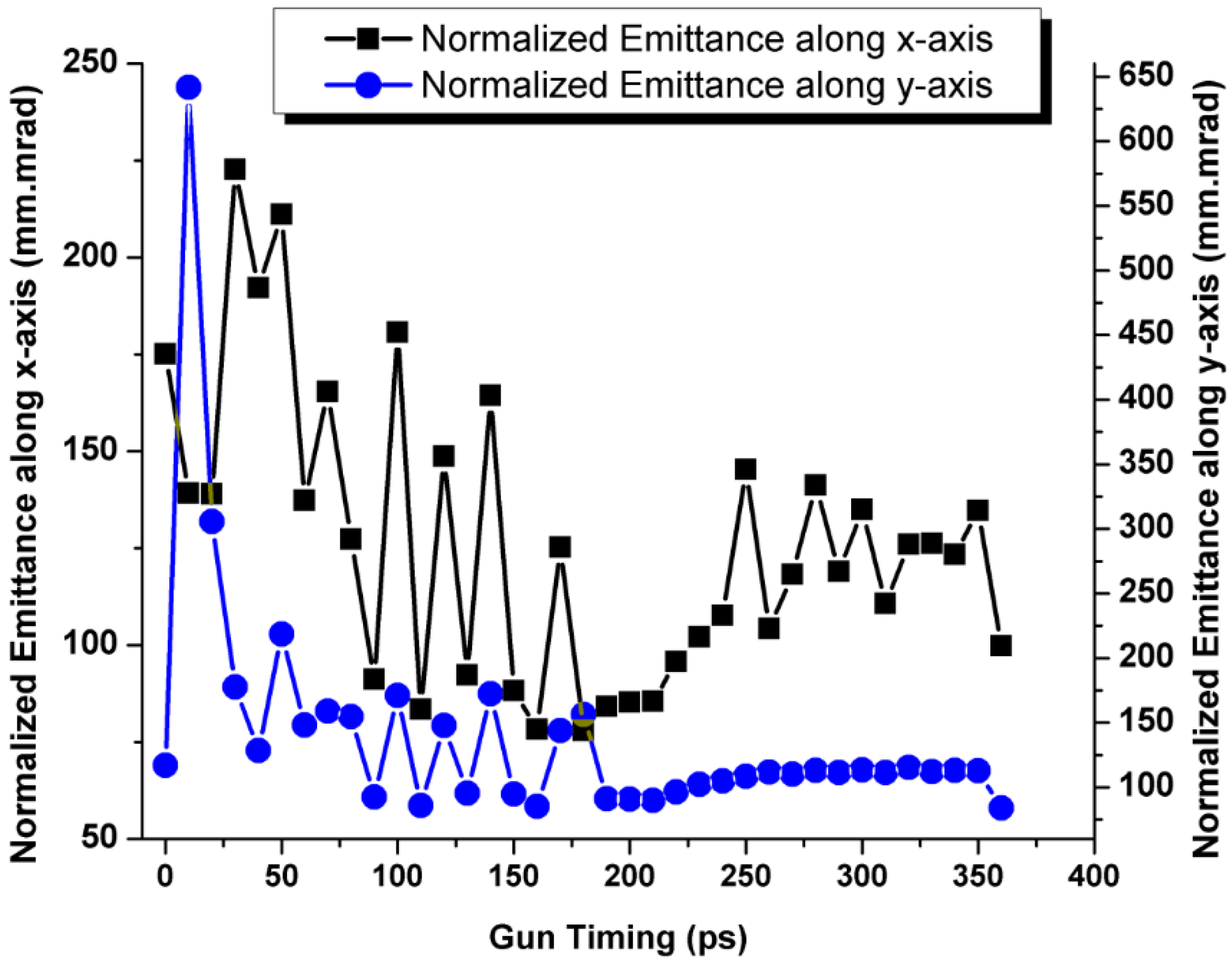
The corresponding parameters of transverse section, average energy, energy spread, phase of the reference particle and normalized XY-emittance were 1.8 cm × 2 cm, 51.62 MeV, 10.81%, 124.39° and 100.70, 21.54 mm mrad (3δ), respectively. Then, the longitudinal jitter of the electron gun trigger timing was simulated from 0 ps to 350 ps. The beam parameters at A0 exit were calculated and are shown in Figure 9 and Figure 10, respectively.
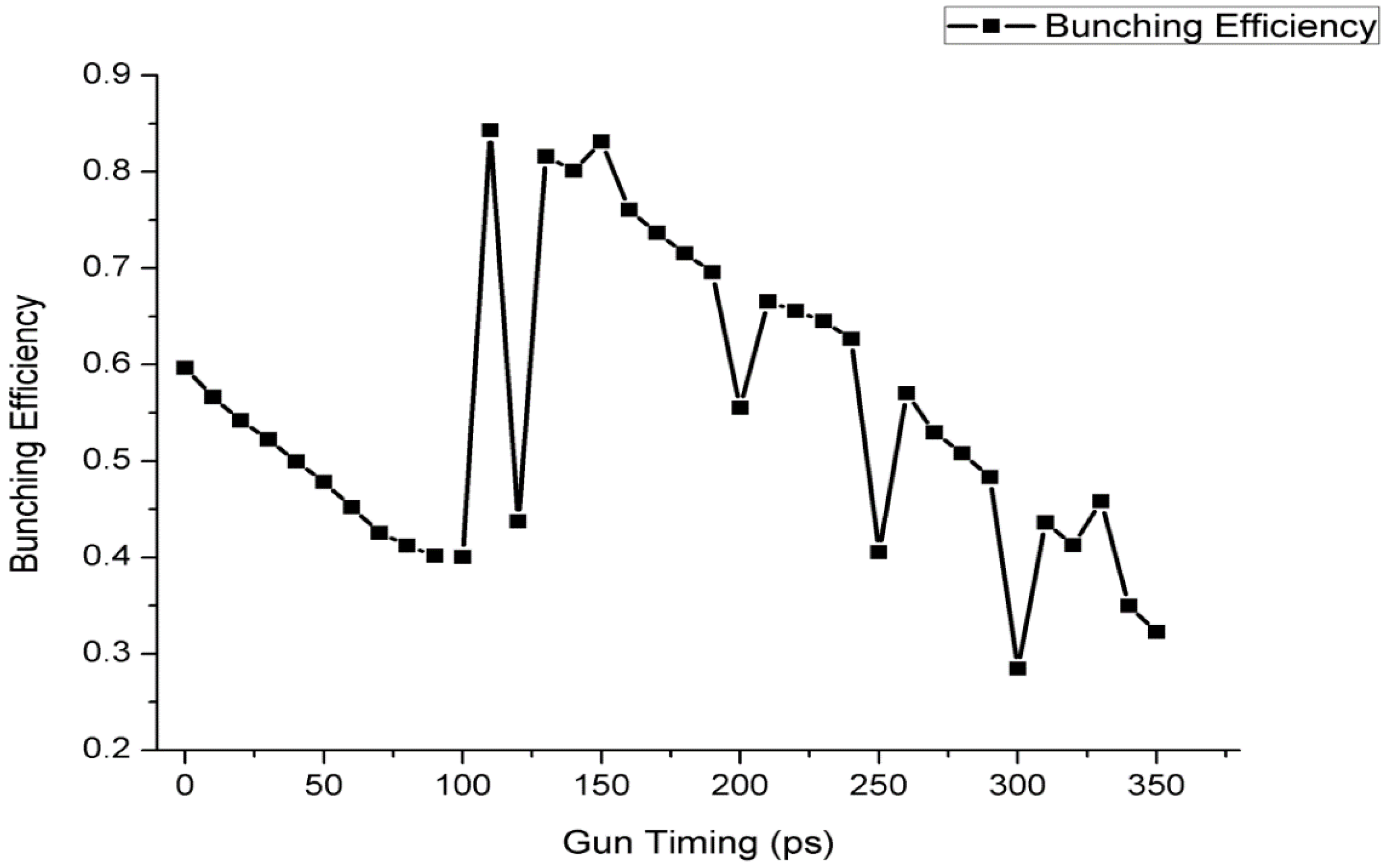
Consequently, the bunching efficiency from the gun to the A0 exit of the Linac changed in a range of 54.70% (from maximum 83.15% to minimum 28.45%), as shown in Figure 11.
From the simulation results, it is obvious that the electron gun trigger timing longitudinal jitter affects the beam performance, including the beam size (profile), average energy, energy spread, emittance and phase of the reference particle. The simulation results of the beam performance are apparently different; the maximum and minimum percentage difference of beam size, average energy, energy spread, phase of reference particle and XY-emittances are 100%, 13.27%, 42.24%, 9.89° and 65.01% and 86.81%, respectively. Therefore, the electron trigger timing should be adjusted to optimize the longitudinal phase of the electron beam to achieve good beam performance and to keep injection efficiency to the storage ring as high as possible. A comparison between maximum and minimum values of beam parameters is given in Table 1.
4. Conclusions
We report the effects to the longitudinal and transverse beam parameters caused by trigger timing jitter to the electron gun in the pre-injector of BEPCII linear accelerator. In the pre-injector of linear accelerators, generally, there are many parameters, which should be properly adjusted. The trigger timing to an electron gun is one of the most important parameters, which should be stabilized within some allowable tolerance. Because any timing jitter larger than the tolerance may affect the longitudinal and transverse beam parameters in the pre-injector, it may not only deteriorate the beam qualities but also cause serious beam loss.
In order to address these issues, we investigated quantitatively the effects to the longitudinal and transverse beam parameters caused by the trigger timing jitter based on experimental measurements along with numerical simulations by using PARMELA code, and calculated the degrees of the deterioration in terms of the beam parameters, that is, the beam profile, average energy, energy spread, phase jitter between the beam and SHBs, and the transverse emittances.
To apply this method, it is very important to evaluate the beam parameters under experimental conditions with some timing jitter in the pre-injector that maintains the beam quality and stability in order to keep the injection rate to the storage rings (or to maintain the peak luminosity) as high as possible, especially in the collider experiments. This paper gives an important step towards further stable operation in linear accelerators.
Acknowledgments
We are highly indebted to Dr. Pei Shilun due to his useful suggestions and discussions. The authors acknowledge the financial support from Institute of High Energy Physics, Beijing, China and University of the Punjab, Lahore-Pakistan.
Author Contributions
All authors contributed equally. MingShan Liu proposed the idea, designed the experiment and collected the data, MingShan Liu and Munawar Iqbal wrote the manuscript and discussed the results.
Conflicts of Interest
The authors declare no conflict of interest.
References
- Liu, M.S.; Iqbal, M. Electron gun jitter effects on beam bunching. Rev. Sci. Instrum. 2014, 85. [Google Scholar] [CrossRef] [PubMed]
- Pei, S.; Wang, S. Tolerance study on BEPCII sub-harmonic bunching system. High Power Laser Part. Beams 2006, 18, 1349–1354. [Google Scholar]
- Pei, S.; Wang, S.; Gu, P.; Geng, Z. Structure optimization of 142.8 MHz sub-harmonic buncher. High Power Laser Part. Beams 2004, 16, 795–799. [Google Scholar]
- Pei, S.; Wang, S.; Liu, W. Two-pulse acceleration for BEPC II injector linac. High Power Lasers Part. Beams 2007, 19, 1537–1542. [Google Scholar]
- Iqbal, M.; Wasy, A.; Islam, G.; Zhou, Z. Finite element analyses of a linear-accelerator electron gun. Rev. Sci. Intrum. 2014, 85. [Google Scholar] [CrossRef] [PubMed]
- Shilun, P. Studies on Two-bunch Acceleration in Electron Linear Accelerator. Ph.D. Thesis, Institute of High Energy Physics, Beijing, China, April 2006. [Google Scholar]
- Chen, Y.; Wang, S.; Pei, G.; Liu, W.; Ye, Q. Beam Commissioning of BEPCII Injector Linac. High Energy Phys. Nucl. Phys. 2006, 30, 562–565. [Google Scholar]
- Pei, G.; Sun, Y.; Chi, Y.; Wang, S. Progress of the Injector Linac Upgrade for the BEPCII. Chin. Phys. C 2004, 28, 1214–1218. [Google Scholar]
- Cui, Y.-Y. Studies of Bunch Length Monitor for BEPCII Linac. Ph.D. Thesis, Institute of High Energy Physics, Beijing, China, June 2007. [Google Scholar]
- Wang, S. BEPCII Linac Upgrade and Beam Commissioning. Chin. Phys. C 2006, 30, 150–152. [Google Scholar]
- Asaka, T.; Kawashima, Y.; Takashima, T.; Kobayashi, T.; Ohshima, T.; Hanaki, H. Method for stabilizing beam intensity and energy in the SPring-8 linac. Nucl. Instrum. Methods Phys. Res. Sect. A 2004, 516, 249–269. [Google Scholar] [CrossRef]
- Young, L.; Billen, J. The Particle Tracking Code Parmela, Los Alamos National Laboratory. In Proceedings of the 2003 Particle Accelerator Conference, Los Alamos, NM, USA, 12–16 May 2003.
Figure 1.
Schematic of the pre-injector.

Figure 2.
Beam current and timing measurement scheme in the pre-injector.

Figure 3.
Single waveform picked up by a BPM with an oscilloscope.
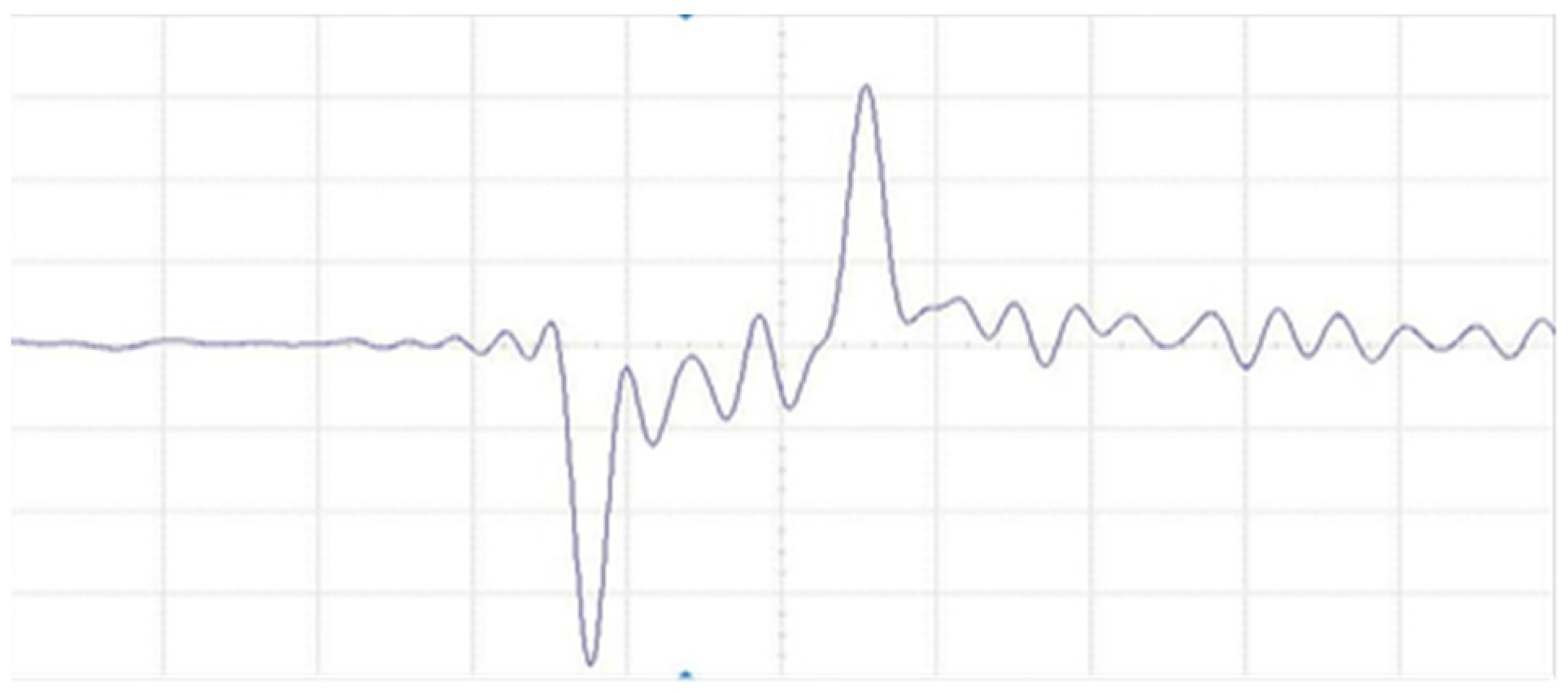
Figure 4.
Beam profile image measured by a profile monitor.

Figure 5.
Signal waveforms measured by the Beam Current Transformers (BCTs).
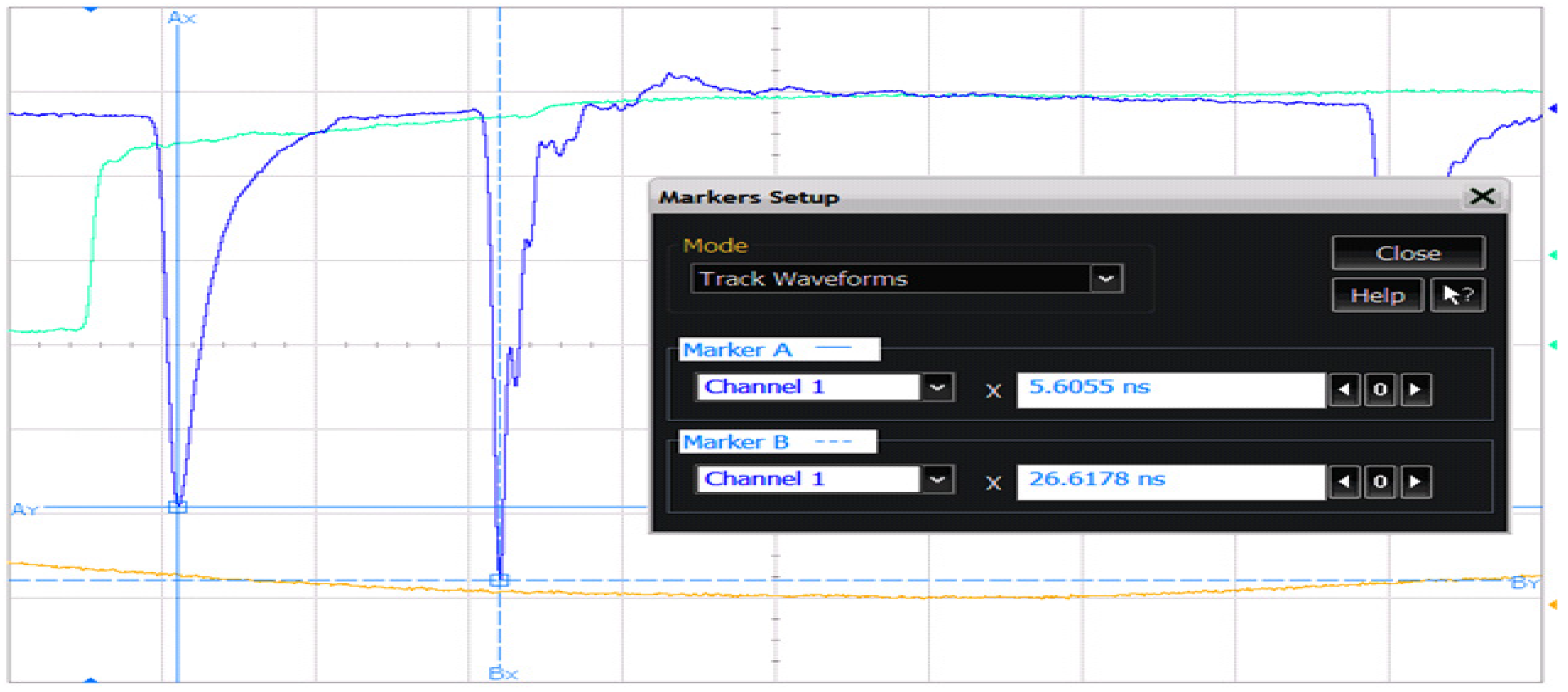
Figure 6.
Persistently stored waveforms measured by the BCT1 and BCT2 under the condition with certain timing jitters.
Figure 6.
Persistently stored waveforms measured by the BCT1 and BCT2 under the condition with certain timing jitters.

Figure 7.
Nominal beam parameters at the A0 exit without any timing jitter.
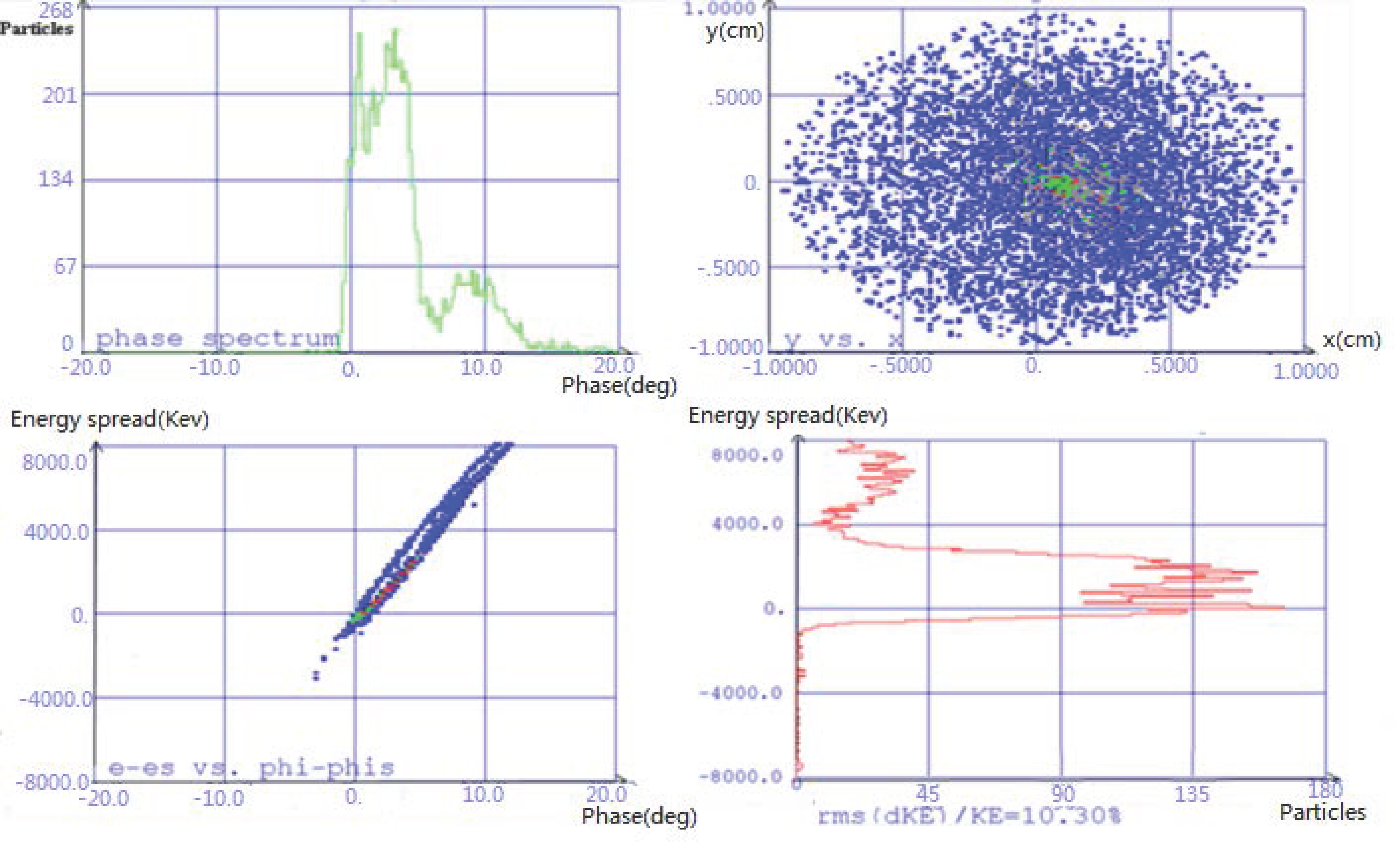
Figure 8.
Beam parameters at A0 exit with 30 ps longitudinal jitter.

Figure 9.
Variations in the beam energy, energy spread, and phase as a function of the gun timing.
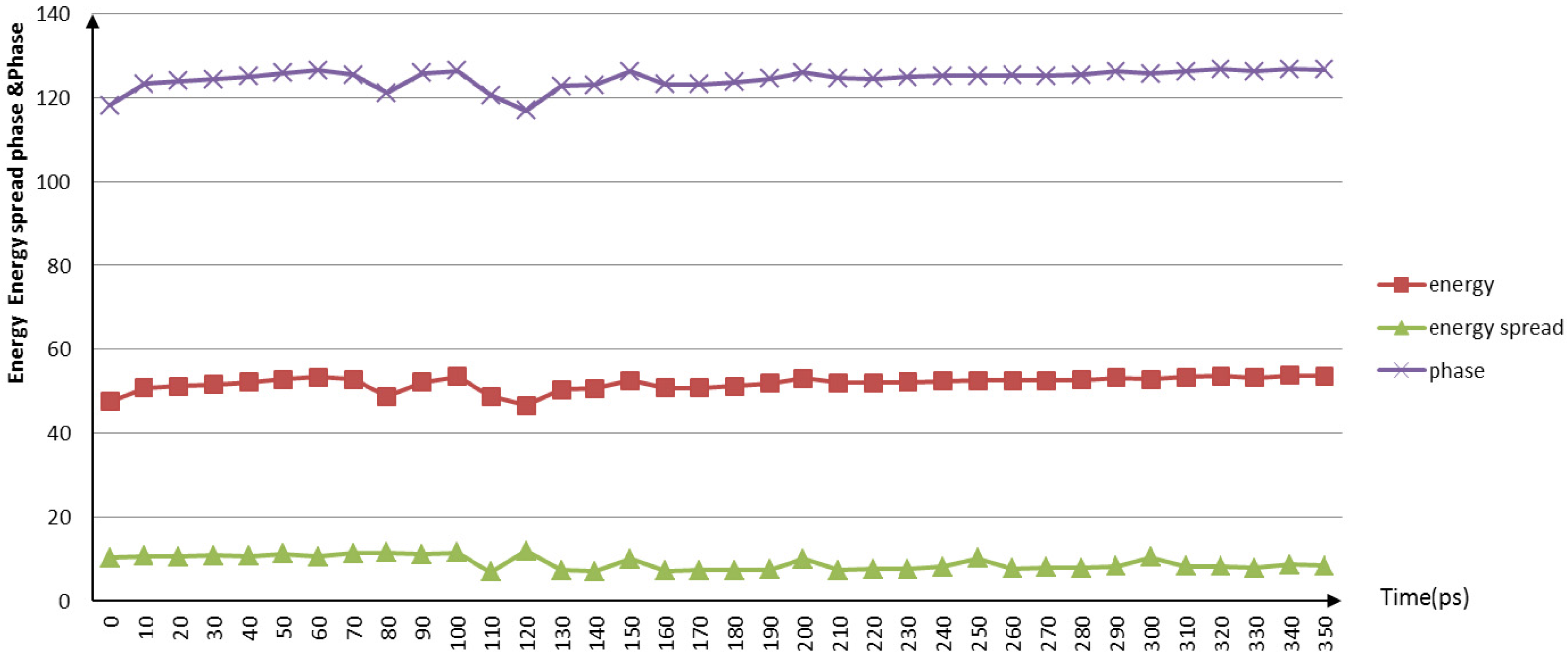
Figure 10.
Variations in the x and y normalized emittance as a function of the gun timing.

Figure 11.
Variations in the bunching efficiency as a function of the gun timing.


| Parameters Range | Beam Profile (cm) | Average Energy (MeV) | Energy Spread (%) | Phase (deg) | Emittance (mm mrad) | |
|---|---|---|---|---|---|---|
| X | Y | |||||
| Min | ≤(1,1) | 46.60 | 6.89 | 116.99 | 78.69 | 13.04 |
| Max | ≥(2,2) | 53.73 | 11.93 | 126.88 | 222.93 | 141.59 |
© 2016 by the authors; licensee MDPI, Basel, Switzerland. This article is an open access article distributed under the terms and conditions of the Creative Commons Attribution (CC-BY) license (http://creativecommons.org/licenses/by/4.0/).
Share and Cite
MDPI and ACS Style
Liu, M.; Iqbal, M. Longitudinal Jitter Analysis of a Linear Accelerator Electron Gun. Appl. Sci. 2016, 6, 350. https://doi.org/10.3390/app6110350
AMA Style
Liu M, Iqbal M. Longitudinal Jitter Analysis of a Linear Accelerator Electron Gun. Applied Sciences. 2016; 6(11):350. https://doi.org/10.3390/app6110350
Chicago/Turabian StyleLiu, MingShan, and Munawar Iqbal. 2016. "Longitudinal Jitter Analysis of a Linear Accelerator Electron Gun" Applied Sciences 6, no. 11: 350. https://doi.org/10.3390/app6110350
Note that from the first issue of 2016, this journal uses article numbers instead of page numbers. See further details here.