1. Introduction
In a pulse-echo ultrasound, ultrasonic waves are reflected at the boundaries of materials with different densities. The reflected echo signals can then be used to visualize structural information of an imaging object by reconstructing the spatial geometry inside the object. Volumetric ultrasound imaging, to acquire additional structural information, has grown rapidly since two-dimensional (2-D) arrays have come into use [
1,
2]. In particular, volumetric ultrasound imaging has been developed primarily for medical applications. Cardiac ultrasound imaging has been one of the clinical diagnostic applications to fully access cardiac anatomy and function as well as to improve quantitative measurements on physiological conditions of the heart [
3,
4]. However, the main technical challenge faced by the volumetric imaging is that an ultrasound system needs thousands of the channels to operate a large number of elements in a 2-D array. To overcome the channel limitation in utilizing the 2-D arrays, various approaches were proposed such as the microbeamformer, the reconfigurable array, and the sparse array [
5,
6,
7,
8,
9,
10]. A sparse array has been suggested by picking array elements in a random or regular manner to minimize the number of required channels [
7,
8,
9,
10,
11]. Once the sparse array set is fixed, the elements in a 2-D array can be directly controlled by an ultrasound system, which can avoid the complicated hardware designs. In addition, the volumetric ultrasound imaging suffers from low frame rates due to the increase in the imaging area and the computational load of the data. However, a higher frame rate is essential for the volumetric cardiac ultrasound imaging in order to provide potentially important diagnostic information on cardiac dysfunction such as valvular and wall motion abnormalities [
3,
4]. Hence, ultrasound imaging using unfocused plane waves was introduced to increase the frame rate by applying a reduced number of beams [
12,
13,
14,
15]. The previous studies showed that the sparse array in a 2-D array could be used with focused transmits [
7,
8]. However, the performance of the sparse array with unfocused transmits has not yet been investigated explicitly. The hardware design for the receive array can be far more complex than that for the transmit array since the formation of three-dimensional (3-D) volumetric images needs to consider time delays from various reconstruction locations in the image. In this paper, a cross-shaped array (hereinafter referred to as the X-shaped array) was selected to simplify the receive configuration by applying the sparse array concept using a smaller number of the elements within the receive aperture. To investigate the feasibility and the limitation of the X-shaped sparse array, we evaluated the applicability of the X-shaped sparse array for high-frame-rate volumetric ultrasound imaging when used with the unfocused plane waves.
2. Methods
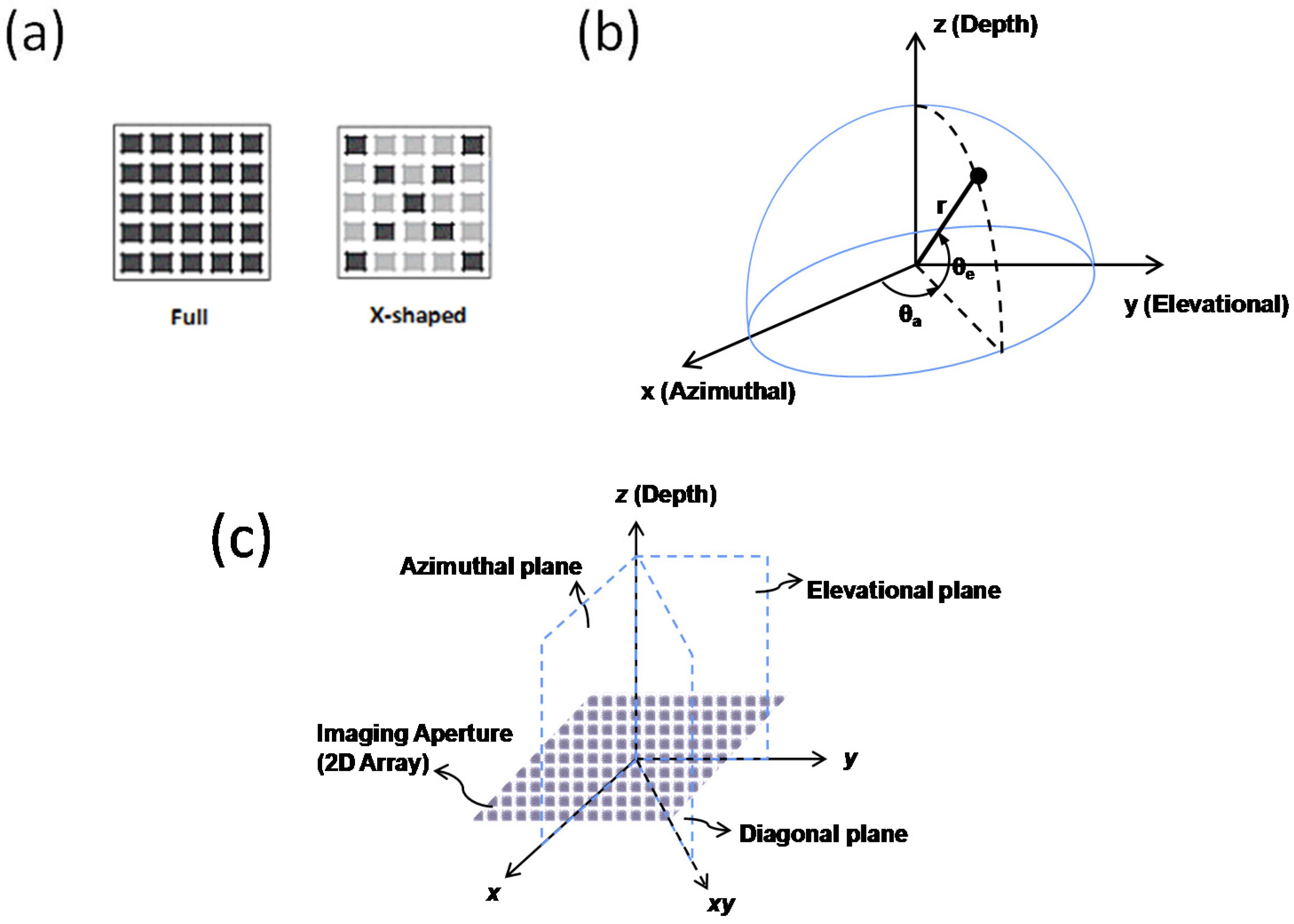
Figure 1 illustrates diagrams of volumetric imaging using a 2-D array (also called “aperture”) that receives pulse-echo signals. The previous studies [
7,
8] showed that an X-shaped array (
Figure 1a) can have an equivalent point spread function (PSF) as the full array (
Figure 1a). Using the geometry in
Figure 1b, the PSFs of the full array and X-shaped array can be expressed in the Fourier domain [
1,
8] as
Here, α = sin(θ
a)·π
d/λ, β = sin(θ
e)·π
d/λ, the 2-D array is
N ×
M, λ is the wavelength of the emitted ultrasound wave,
d is the pitch of the elements, and θ
a and θ
e are the angles in azimuthal and elevational planes, respectively. For volumetric imaging, cross-sectional planes can be selected in the elevational (
y-
z plane, α = 0), in the azimuthal (
x-
z plane, β = 0), and in the diagonal (
xy-
z plane, α ≠ 0 and β ≠ 0) planes, as shown in
Figure 1c. While the response of an X-shaped array (
HX-shaped) is equivalent to that of a full array (
HFull) for both the azimuthal and the elevational planes, Equations (1) and (2) are not equivalent in the diagonal plane, as neither α nor β are zero.
The PSFs of X-shaped sparse array with unfocused ultrasound waves was demonstrated in ultrasound fields of 2-D array (64 × 64 elements, 250 μm pitch, and a center frequency at 3.0 MHz). A Field-II program was used to simulate behaviors of the unfocused (i.e., plane wave) transmit beams for this study [
16,
17]. Two-way PSFs of full-transmit and full-receive (FT-FR) arrays and full-transmit and X-shaped receive (FT-XR) arrays were calculated at a 30 mm depth. The envelopes of the PSFs were shown, and the side-lobe levels were calculated at the positions of the side-lobe peaks [
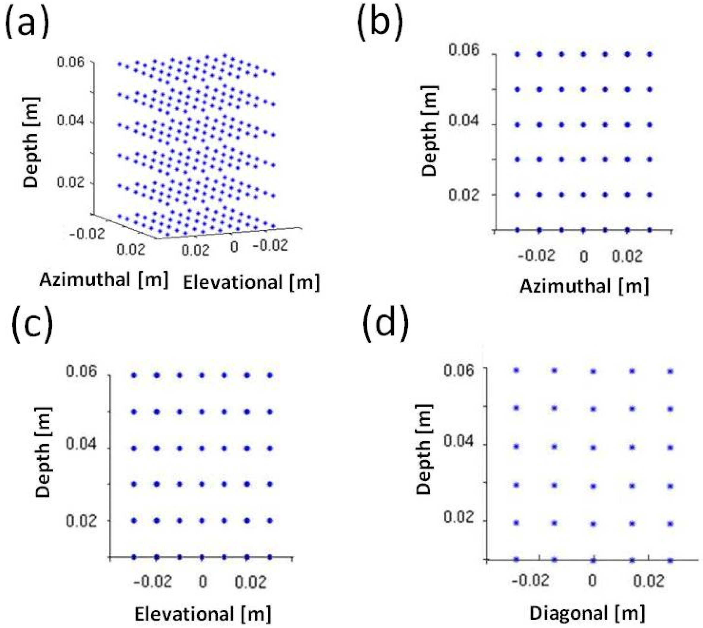
18]. In addition, 3-D point target phantom was simulated to evaluate image quality from the array configurations for the volumetric imaging. As shown in
Figure 2, the 3-D phantom contained regularly-positioned grid points. Each grid scatter point was equally spaced in the azimuthal, elevational and depth directions with an interval of 10 mm. RF data were collected from the Field-II simulations [
16,
17] using the same parameters of the PSF simulations, by transmitting a plane wave beam using the full aperture (i.e., 16 mm × 16 mm). To cover a pyramidal volumetric imaging area, delay-and-sum beamforming [
19] was used to reconstruct 90 × 90 scan lines. For the unfocused FT-FR and FT-XR, we simulated B-scan images in the diagonal planes and the simulated images were displayed in a 40 dB dynamic range.
To enhance the quality of images generated from unfocused FT-XR, a dynamic transmit focusing (DTxF) method was applied to reconstruct 2-D imaging planes by utilizing coherent angular compounding [
20,
21,
22,
23].
Figure 3 presents a geometrical description of the coherent angular compounding imaging applied in the simulation. Transmit time delay at each element was calculated as
xsinθ
x +
ysinθ
y, where θ
x and θ
y represent the inclination angles of the plane wave from
x- and
y-axis, respectively [
22]. The coherent angular compounding was performed by coherently summing the received signals from several plane waves transmitted at different angles (i.e., varying θ
x and θ
y). For image reconstruction, the time delay was calculated by using the time delays of both transmit and receive to coherently align the received signals before summation. Then, the plane waves were rotated around the point placed behind the transducer as shown in
Figure 3 [
21,
22]. Thus, a transmit delay offset (
toffset) was added to the time delay between the array and every imaging point. According to previous studies [
20,
21,
22,
23], the coherent summation of the received signals from plane wave transmits at different angles can generate an equal performance of a focal point of the focused transmits. Therefore, coherent angular compounding can achieve DTxF by creating foci at every imaging point with the unfocused transmit beams. The optimum angular increment (Δθ = λ/
D) and the number of transmit angles (
D/λ·
F#) for the angular compounding were calculated to cover the imaging angle to avoid grating- or side-lobe artifacts [
16]. Then, using the optimum parameters, the simulations for the unfocused FT-XR employed a 31 × 31 transmit angles with a step increment of 1.8° in both azimuthal (θ
x) and elevational (θ
y) directions.
When κ × κ plane waves are transmitted, frame rate decreases by κ2 times. Since the X-shaped array could degrade the image quality in the diagonal plane (i.e., α ≠ 0 and β ≠ 0 in Equation (2)), plane waves tilted in the diagonal direction (i.e., θx = θy) were selected to investigate the enhancement of the image quality in the diagonal plane using reduced number of transmits. In addition to the experiment with the optimum parameters for coherent angular compounding, the tilted plane waves at 11 different angles with a step increment of 5° in the diagonal direction (θx = θy) were employed. Using the coherent angular compounding, 90 × 90 scan lines were reconstructed from the acquired data.
Table 1 shows a quantitative summary including numbers of transmit and receive elements, number of transmits per frame, frame rate, and signal-to-noise ratios (SNR) gain. In the current study, SNR gains relative to a single element’s SNR were evaluated. Thus, the SNR gains for the unfocused transmit were
, where
Nt is the number of transmit elements,
Nr the number of receive elements, and
Nbeam the number of beams for a frame. To predict the noise susceptibility of an X-shaped array, relative imaging SNR were estimated for unfocused FT-FR and FT-XR while the number of elements (
N ×
N) of a 2-D array increased from 8 × 8 to 64 × 64. To numerically compare with a conventional one-dimensional (1-D) linear array, a SNR relative to 100 elements linear array was calculated by subtracting the SNR gain of a 100 elements array (i.e., 100√100) from the SNR gains of the FT-FR and the FT-XR. The 1-D linear array had the same element size and pitch as the 2-D arrays did, and all elements were used to transmit as well as to receive with focusing. The relative imaging SNRs of the FT-XR in conjunction with DTxF using
N ×
N, 31 × 31, and 11 tilted plane waves were also evaluated, of which the SNR gain was multiplied by a square root of the number of the transmitted plane waves, to explore variations in the noise susceptibility of the X-shaped array for volumetric imaging.
3. Results and Discussion
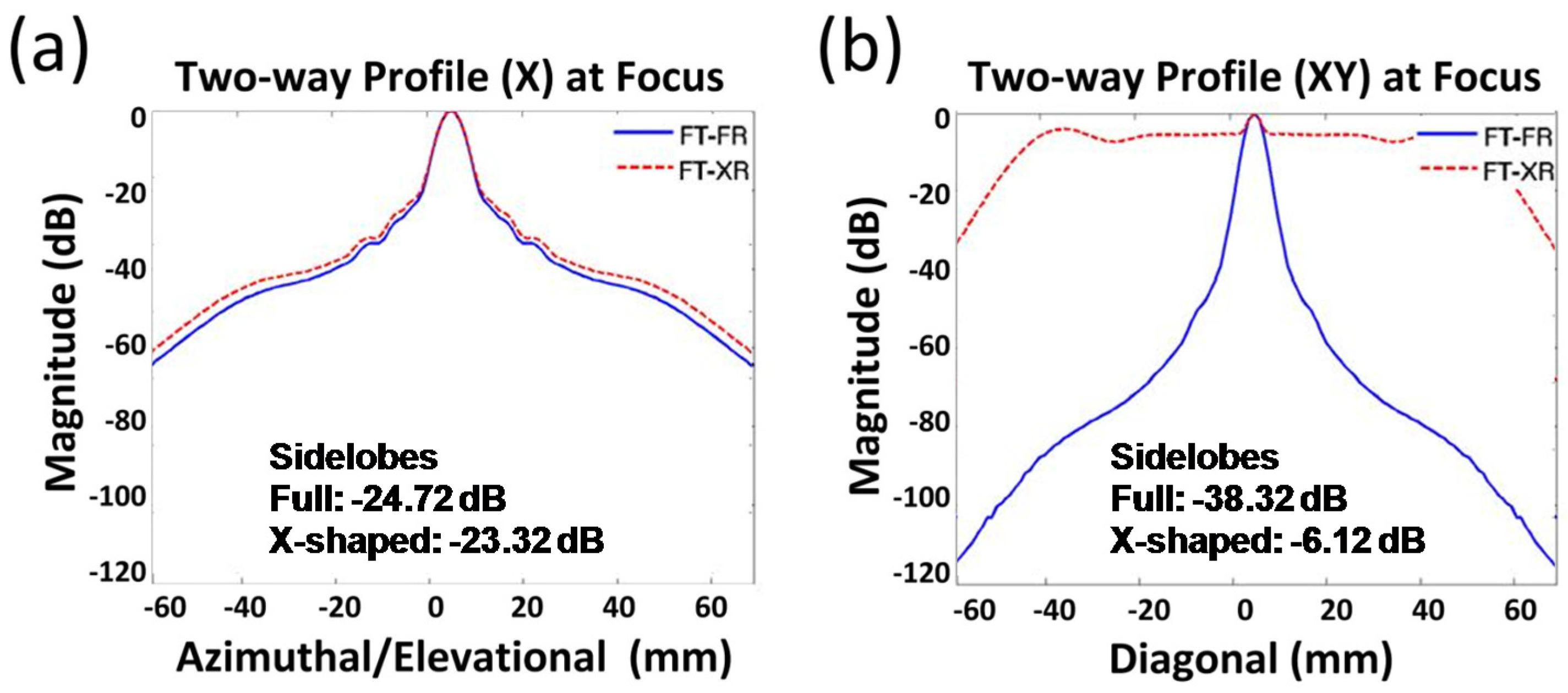
Figure 4 presents analytic simulations of two-way PSFs using unfocused FT-FR and FT-XR in the azimuthal (
x-
z plane in
Figure 1c) and the diagonal (
xy-
z plane in
Figure 1c) planes. Almost identical responses were found in the azimuthal plane for both the FT-FR and the FT-XR (
Figure 4a) with comparable magnitudes of side-lobes (i.e., −24.72 dB for FR vs. −23.32 dB for XR). However, the PSF of the FT-XR in the diagonal plane (
Figure 4b) significantly increased the side-lobe level by up to 32 dB compared with the FT-FR (i.e., −38.32 dB for FR vs. −6.12 dB for XR). The main lobe (i.e., largest field strength) was hardly recognizable in the two-way PSF of the unfocused FT-XR (
Figure 4b) as the difference between the main-lobe and the side-lobe levels was less than 6 dB. Thus, the X-shaped array was found to be ineffective for unfocused ultrasound imaging, particularly when the imaging plane was rotated at a certain angle (i.e., α ≠ 0 and β ≠ 0 in Equations (1) and (2)).
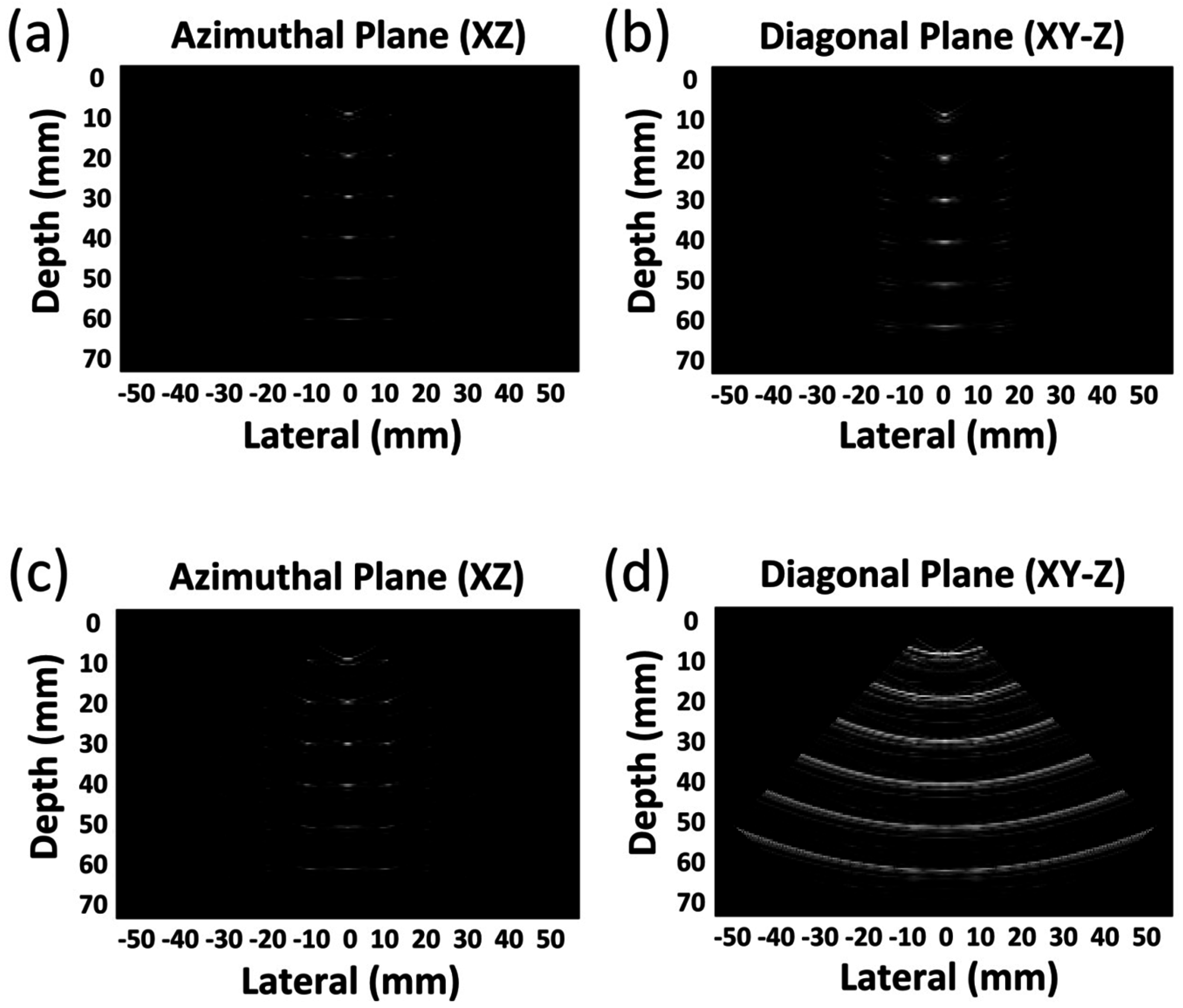
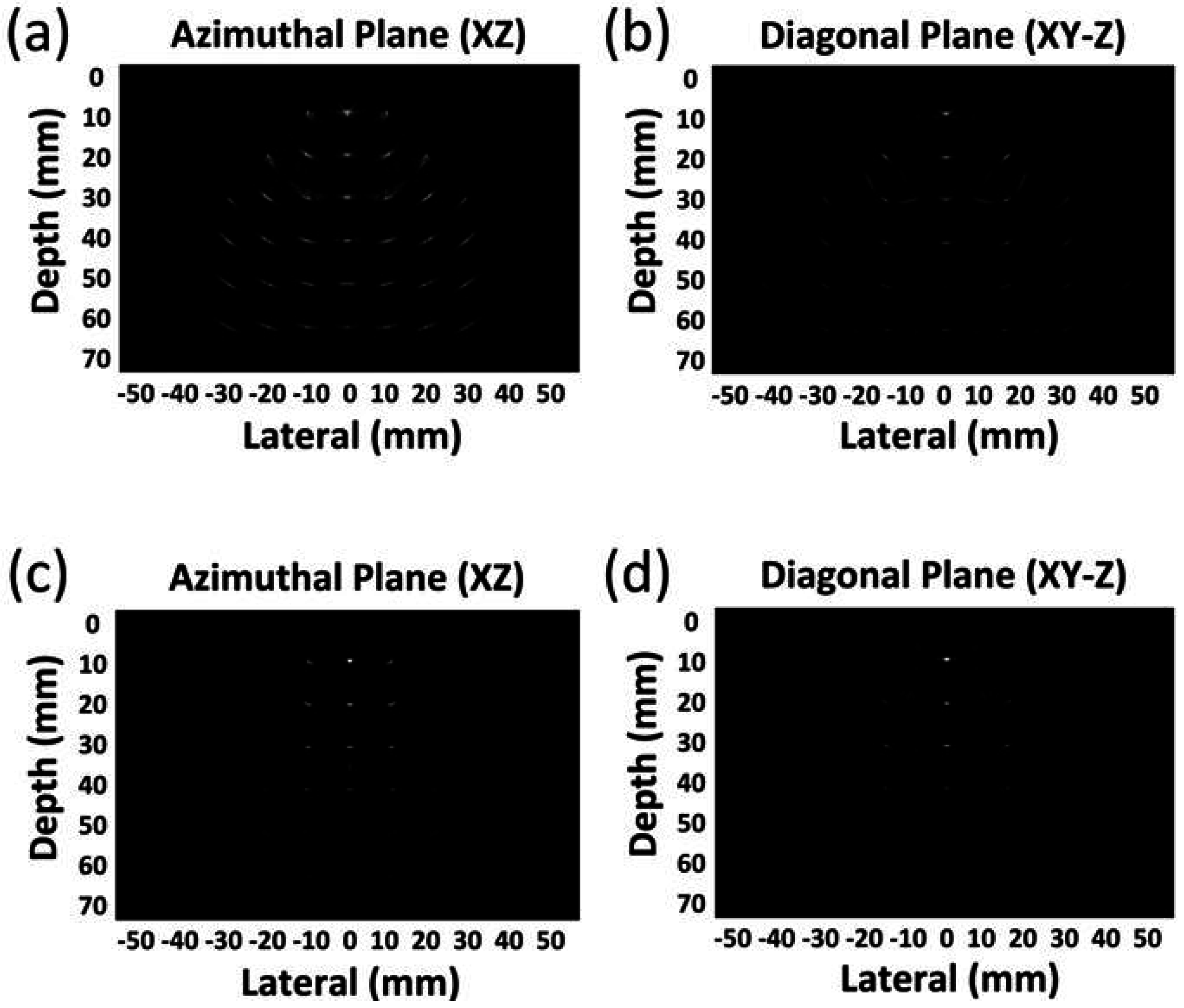
Figure 5 presents the simulated images using FT-FR (
Figure 5a,b) and FT-XR (
Figure 5c,d) for diagonal planes. Due to the transmission of a plane wave using the whole aperture, the beam width of the wave was almost equal to the size of the aperture of the array. Thus, the point targets outside of the beam width (i.e., 16 mm in the azimuthal plane and 22 mm in the diagonal plane) were hardly imaged as demonstrated in
Figure 5. While the unfocused FT-FR in the diagonal plane (
Figure 5c) displayed the point targets, the image in the diagonal plane for the FT-XR (
Figure 5d) was significantly degraded, making the point targets almost unrecognizable. This result clearly demonstrates that the unfocused FT-XR was considerably degraded in the diagonal direction, which was also observed in the simulation of the PSFs of the unfocused FT-XR (
Figure 4b). Therefore, it is conceivable that the unfocused FT-XR may hardly be used for volumetric imaging in the diagonal plane.
Figure 6 shows azimuthal and diagonal images reconstructed by DTxF for unfocused FT-XR.
Figure 6a,b resulted from the optimum angular increment (31 × 31 plane waves) and
Figure 6c,d resulted from the reduced number of plane waves (11 in the diagonal direction). Overall, the point targets in both the azimuthal (
Figure 6a,c) and the diagonal planes (
Figure 6b,d) were clearly visible in comparison with those of a single plane wave transmit (
Figure 5). Although the point targets reconstructed from 11 plane waves (
Figure 6c,d) were hardly clear compared with those from the optimum parameters (
Figure 6a,b), it was still conceived that the reduced beams in the degraded plane were feasible to improve the quality of the volumetric images. Since smaller areas of the beams were overlapped as the point targets were located deeper and farther from the center, it was observed that the PSFs improved at the closer and shallower depths. In fact, the observation was more noticeable in the images using the reduced beams (
Figure 6c,d). In particular, the point targets in the diagonal plane (
Figure 6b,d) were dramatically sharpened (i.e., less blurred) compared with
Figure 5d. Thus, the DTxF method was clearly effective in improving the image quality, particularly where the point spread function was significantly degraded by the unfocused FT-XR.
For an
N ×
N element array, FT-XR can utilize 2/
N times less receive elements (i.e., 2
N) than FT-FR (i.e.,
N ×
N), so an X-shaped array can have high noise susceptibility. Hence, it is necessary to estimate the SNR in order to employ the X-shaped array for imaging applications. As shown in
Table 1, the SNR gain of FT-XR is √
N/√2 times lower than that of FT-FR for a single plane wave transmit.
Figure 7 displays the relative imaging SNRs calculated for the FT-FR and the FT-XR as a function of the number of the elements in the 2-D array. Since the SNR gain was calculated relative to that of a 1-D array with 100 elements, 0 dB means the same SNR gain as that of the 1-D array. When 4096 (64 × 64) elements were used, the SNR of the FT-XR was approximately 30 dB lower than that of the FT-FR, clearly indicating that the FT-XR was less robust to noise than the FT-FR. Thus, the FT-XR significantly compromised the SNR of the reconstructed images in comparison with the FT-FR. However, the SNR of the FT-XR became equivalent to that of the FT-FR when 31 × 31 plane waves were used with the DTxF method (
Figure 7). For
N ×
N plane waves, FT-XR employed with the DTxF achieved a 40 dB higher SNR than the FT-FR did, implicating that the limitation of image quality could be readily compensated by transmitting a higher number of beam angles. When the plane waves of
κ angles were transmitted for the unfocused FT-XR,
κ-overlapped plane-wave fields could be used for the coherent angular compounding to increase SNR by a factor of
. In turn, for the FT-XR with unfocused ultrasound imaging, the DTxF method can improve the point spread function and compensate for the loss of SNR resulting from the reduced number of the receive elements. While the SNR can improve, the frame rate can be lowered by the number of transmitted beams (1/
κ ~ 1/
κ2 where
κ <
N) as shown in
Table 1. The number of transmitted beams can be controlled by adjusting the targeting SNR and frame rate of the image. In spite of a decrease in the frame rate, the implementation of the X-shaped sparse array with the unfocused ultrasound waves can be a feasible method for volumetric ultrasound imaging when a receive channel limitation exists. Furthermore, the proposed method can achieve an image quality equivalent to the full array of a single plane wave by employing the DTxF method.


