Article

Wear Characteristics of Metallic Counterparts under Elliptical-Locus Ultrasonic Vibration

School of Mechatronics Engineering, Harbin Institute of Technology, Harbin 150001, China
*
Author to whom correspondence should be addressed.
Appl. Sci. 2016, 6(10), 289; https://doi.org/10.3390/app6100289
Submission received: 13 July 2016 / Revised: 26 September 2016 / Accepted: 28 September 2016 / Published: 11 October 2016

Abstract

:
Wear behavior is influential to improve friction drive and wear lifespan of actuators or motors, which work at an elliptical locus vibration. Sliding wear tests of metallic friction pairs are conducted by a laboratory rig of ultrasonic vibration. Surfaces of the different metallic sliders are characterized using surface roughness, Abbott curves and fractal dimension. Results show that surface roughness is reduced to varying degrees in the metallic sliders due to ultrasonic polishing and/or micro-rolling effect. Variations in the fractal dimensions of contact surfaces are consistent with that of surface roughness. Wear traces demonstrate that plastic deformation and cracking are the primary failure modes. Where the driving tip on the slider is in intermittent contact followed by impact effects, ripples of 3~5 μm traces suggest the occurrence of fretting in duralumin sliders. Nodular cast iron showed a favorable performance during running of ultrasonic motor, exhibiting a stable output performance and durable wear life.

Graphical Abstract

1. Introduction

Elliptical-locus ultrasonic vibration has been favored in recent years for its capability to cut non-conductive, brittle workpiece materials [1]. The reason is that the frictional force between the tool rake and the chip is effectively reduced by reversing the frictional direction, and the reversed frictional force assists the chip to flow out [2]. More importantly, the development of ultrasonic vibration has brought about new trends in the miniaturization and multifunctionality of special sensors, actuators and/or motors. Compared with conventional electromagnetic motors, remarkable advantages of the ultrasonic motor [3,4] make itself an attractive technology for applications in civilian industries, automation production, biological medicine, precision engineering, the aerospace industry, and others. Because of such promising applications in various industries, research into improving the output power, efficiency and longevity are quite valuable. Currently, several inevitable problems yet exist to be solved before moving the ultrasonic motor from laboratories to factories. As is well-known, ultrasonic vibration in different existing forms play specific roles in components. Unilateral vibration either in sliding direction or normal to sliding direction would reduce the coefficient of friction [5], thus the in-plane ultrasonic vibration is hardly devoted to the power transmission by using ultrasonic vibration [6]. Fundamentally, ultrasonic motors are driven through ultrasonic vibration and friction action [7]. Inherent friction and wear between the driving tip and the driven slider become crucial considerations for the output performance and life-span of ultrasonic motors. Therefore, high coefficient of friction and low wear rate, specifically, are the primary goal of ultrasonic motor design [8] and parameterization. Besides, dynamic contact of the driving tip and the slider, especially for standing-wave motors, is intermittent and impacting [9,10], resulting in severe wear and material loss over traveling wave motors [11]. In addition, special requirements for the drive signals of different vibrators are necessary for sufficient impedance matching [12], and have not yet been standardized; this problem would be enhanced by the dynamic contact process, with a consequence of the erratic output performance of ultrasonic motor induced by the variable friction force. Last but not least, ultrasonic motors make a concession to the service life of the contact interface, thereafter the output mechanical power is small and their working efficiency needs improve further. Consequently, friction and wear of the contact surfaces between the stator and vibrator are critical for both output characteristics and service life-span of ultrasonic motors. This issue is related to kinematics of driving tip, dynamic contact mechanics of contact interfaces, friction materials of counterparts, wear mechanisms and/or modes, and so on. Given the contact interface of a driving tip and a slider of standing-wave ultrasonic motor turn into a critical and urgent problem for engineers and technologists, design of friction materials and comprehension of wear mechanisms for the interface of driving and driven parts would play an effective role.
Relatively little research currently exists regarding the optimization of surface characteristics or illustration of wear mechanisms for standing-wave ultrasonic motors. Lee et al. [13] reported that stainless steel drive shafts and sliders exhibit favorable dynamic behaviors in linear ultrasonic motors. Tribological performances of the friction pair of a middle carbon steel driving tip and alumina slider were investigated [14,15], where results showed that friction increases with the increase of preload applied to the contact surface, higher temperature, and decrease of sliding speed and humidity. Yamaguchi et al. [16] compared two kinds of alumina ceramic surfaces with different roughness, presenting to the relatively smooth surface with relatively low specific wear amount. However, influence of surface roughness and/or topography on wear behaviors is vacant. Further, roughness changes with material performances are unknown to hinder the optimization and alternation of friction materials for the contact interface. Archard pointed that the area of contact could be proportional to the load even with purely elastic contact, and modeled surface roughness as a set of stacked hemispheres whose radii reduced as the height of the stack increased [17]. Further, the contact deformation depends on the topography of the surface, Greenwood and Williamson established a criterion for distinguishing surfaces which touch elastically from those which touch plastically [18]. Rough surfaces are modeled as two-dimensional, isotropic, Gaussian random processes, and analyzed with the techniques of random process theory [19]. The degree of complexity of a working surface can be represented by a value called fractal dimension [20,21]. The fractal dimension is identified as an intrinsic property of such a multiscale structure and the Weierstrass–Mandelbrot (W–M) fractal function is used to introduce a simple method of roughness characterization [22,23]. Fractal analysis [24,25,26], an effective tool for friction and wear behavior of the contact surface [27], could provide new insights for surface analysis and characterization for ultrasonic motors.
Among the existing wide variety of standing-wave ultrasonic motors (SWUMs), the linear ultrasonic motor with a V-shaped vibrator (VUM) is favored and preferred for its uncomplicated structure and excellent output performance [28,29]. Note that former wear investigations of standing-wave ultrasonic motors with a V-shaped vibrator were conducted by model experiment. For instance, linear ultrasonic motor in normal operation usually is the reciprocated sliding, which is usually replaced by the rotation motion for simplification. Differences between reciprocated sliding and rotation motion may bring out incompatible knowledge in friction mechanisms and wear modes. Especially, inertia of such two ways motion would result into different effects on surface topography and wear behavior of ultrasonic motors. Thus, the reciprocated sliding way is alternative in this study.
The purpose of this study is to analyze the worn surfaces of sliders and investigate wear behaviors of metallic materials under elliptical-locus ultrasonic vibration. Worn surfaces are characterized by surface roughness parameters, Abbott curve, fractal dimension and confocal laser-scanning microscope. Forming a more complete understanding of exact wear mechanisms at work in the driving tip and the driven slider is also of interest to sketch and/or design contact interface for standing-wave ultrasonic motors.

2. Experimental Details
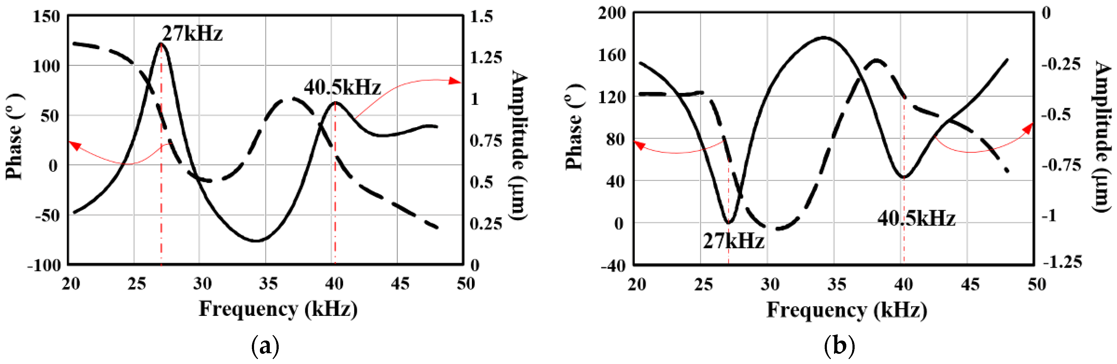
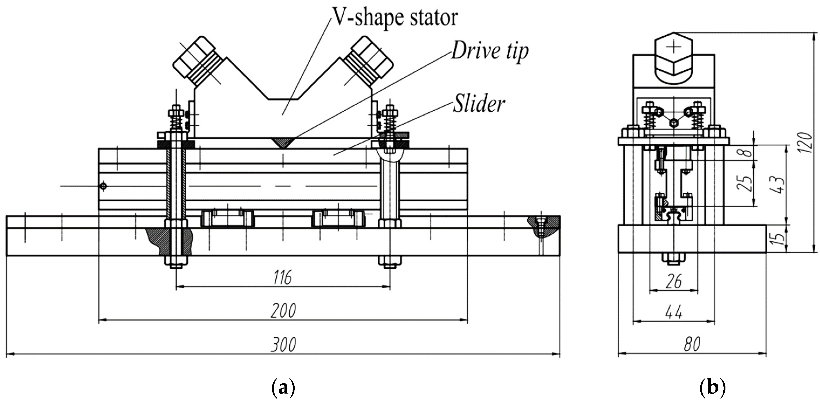
2.1. Apparatus

In order to investigate the surface characteristic and wear behavior of metallic materials under elliptical locus ultrasonic vibration, a laboratory rig based on VUM with two bolt-clamped Langevin transducers was setup, as shown in Figure 1. The rig consisted of a V-shape vibrator, a shell, a slider, and flexible fixing components. The V-shape vibrator was installed at the 2A12 alloy shell, which was supported on the steel base with flexible fixing components. The flexible fixing components consisted of four groups which each had a spring, screw, screw nut, and backup plate. It was rather easy to control the pre-load applied on the contact surface of driving tip and slider through the spinning length of the screw with the help of the springs. The spring stiffness was 4 N/mm. The slider was fixed on the I-beam using six cap screws. The I-beam was fixed on the upper surface of two slide blocks, as well. The linear motion unit (HIWIN®, MGN9C3R300ZOCN, Taichung, China) consisted of blocks, and a guide was installed on the basement. The I-beam then reciprocated motion along the guide once the driving tip began to drive the slider. Considering the net weight of the slider system, the nominal load can be estimated as 1 N. In addition, two position switches were used for an open loop control to excite both actuators with the same frequency, and to change the phase between the excitation of the left and the right Langevin transducers to reverse the direction of slider motion. The time delay at the two extreme positions was 0.2 s.
A V-shaped stator consisting of two Langevin type transducers was fabricated in trial. Eight PZT4 circular elements were used for one transducer. The dimensions of the elements are 20 mm in outer diameter, 6.5 mm inner diameter, and 2.3 mm in thickness. For the operation of an ultrasonic motor, the two vibrators are driven by two electrical sources with a phase difference of 90 degrees, where one of which is a sine function of time and the other is a cosine function of time.
According to modal and harmonic analyses, the motion mechanism of V-shape vibrator proposed by Kurosawa et al. [28] is verified in this study. The vibration mode consists of both symmetric and antisymmetric vibrations, as shown in Figure 2, by longitudinal tension-and-compression. Flexural vibration is also excited at the driving tip for coupling. Symmetric vibration results in vertical vibration, whereas antisymmetric vibration results in horizontal vibration. Horizontal and vertical displacements generate the elliptical locus of the driving tip. Note that, in the model analysis, the V-shape vibrator as a whole is consider 2A12 alloy with ABAQUS, and the contact action between the driving tip and slider is omitted. The boundary condition of the V oscillator coincides with the actual working process. The flange of the vibrator is fixed by three symmetrical screw holes.
Homonymic response plots are shown in Figure 3. The resonance frequencies of the 1st and 2nd modes in the ultrasonic domain are 27 kHz and 40.5 kHz, respectively. Though the amplitudes, both in the horizontal and vertical directions at 27 kHz (1.33 μm and 1.04 μm), are larger than at 40.5 kHz (0.97 μm and 0.81 μm), the dynamic forces at 40.5 kHz are larger than the forces at 27 kHz.

2.2. Materials and Methods

Alternative friction pairs of metallic that are particularly machinable, retrievable and inexpensive are most desired for standing-wave motors. In this study, contact interfaces of VUM consist of 2A12 alloy tips and metallic sliders. Material properties of friction pairs consisting of V-shape vibrators of 2A12 alloy and metal sliders (45 steel, quenched 45 steel, 7075 aluminum alloy, low-alloy structural steel Q345B, and nodular cast iron QT700) are shown in Table 1.
Wear tests were carried out under dry conditions in air at room temperature with a relative humidity of 45% ± 5%. Before each wear test, the surfaces of the driving tips were polished with abrasive paper #800 to ensure the reproducibility of test conditions. The operating conditions of ultrasonic motors are provided in Table 2. The amplitude of the exciting voltage is 150 V and the driving frequency is 39.8 kHz. The output power and thrust force of ultrasonic motors at a driving frequency of 39.8 kHz is higher and more stable than that of other frequencies under the uniform of applied preload and driving voltage.
To investigate surface characteristics and wear behavior of the sliders made of different metallic materials, statistical analysis in this study was carried out on the roughness parameters [30], such as the arithmetical mean deviation of the profile Ra, the maximum height of profile peak Rp, the maximum depth of profile valley Rv, and the mean spacing of local peaks of the profile Rs.
{ R a = 1 l 0 l | h ( x ) | d x R p = max [ h ( x ) ] , 0 x L R v = min [ h ( x ) ] , 0 x L R s = 1 n i = 1 i = n S i = S 1 + S 2 + S 3 + ... + S n n
A roughometer surface roughness measuring instrument (JB-4C, Shanghai, China) was used to measure the surface roughness parameters before and after wear tests. This instrument conformed to international standards ISO05436 and ISO11562. In addition, wear topography of contact surfaces for the sliders made of different metallic materials was investigated using a metallurgical microscope (MM, CMM-20, Shanghai, China) accompanied by a confocal laser-scanning microscope (CLSM, OLS3000, Tokyo, Japan).
Fractal dimensions of contact surfaces were analyzed by power spectral density method before and after wear tests. Weierstrass-Mandelbrot (W-M) function is non-differentiable and continuous, which can describe multi-scale surface profile, as follows [22]:
z ( x ) = G D 1 n = n 1 cos 2 π γ n x γ ( 2 D ) n
where D is the fractal dimension, G is the scaling constant, and the frequency modes γn corresponds to the reciprocal of the wavelength of roughness, as γn = 1/λn the parameter n1 corresponds to the low cut-off frequency of the profile under measured. Therefore, the power spectrum z(x) obeys the power law relationship of the form:
S ( ω ) = G 2 ( D 1 ) 2 ln γ 1 ω ( 5 2 D ) ,   γ n 1 < k <
According to the abovementioned equation, fractal dimension is evaluated from the slope β of a least-square regression line fit to the data points in log-log plot of power spectrum as 5 − 2D = β [31,32]. The slope of the log-log relation for local distribution determines the fractal exponent of the surface [33]. Note that white noise in the PSD (present for long wavelengths) is omitted during the linear representation [34].

3. Results

3.1. Surface Characteristics

3.1.1. Surface Roughness

Surface roughness of sliders is characterized using the stylus method. Among the various surface roughness parameters, Ra is a comprehensive index of surface roughness due to plastic deformation, fracture mechanisms, adhesion and transfer, and surface oxidation. Chaotic changes in surface roughness create a difficult task, in verifying the mode(s) of strength failure and material loss. Rp indicates the maximum height of the asperities, mainly related to the protuberance of the plastic deformation and plowing component. Similarly, dimensions of valleys and hollows, induced by plastic deformation and wear loss result from micro grinding and micro cutting mechanisms, are characterized by Rv. Representative parameters of surface roughness of metallic sliders before and after wear are shown in Table 3.
Surface roughness values for the sliders made of different metals are reduced after wear. The surface roughness Ra of the 45 steel slider turns into a Ra of 0.336 μm. Compared to the initial state (Ra = 0.64 μm), surface roughness decreased by 47.5% after wear (100 m). For the purpose of evaluating the wear resistance of different metal sliders, a variable quantity of surface roughness in the unit wear length (1 m) was adopted here. Wear resistance of the unit wear length for 45 steel slider Ra decreased by 0.47%, and Rv decreased by 0.18%. Compared to an ordinary 45 steel slider, the 45 steel slider after quenching showed a higher value of surface hardness. Surface roughness of the slider of quenched 45 steel was still high after milling machining. After wear test (400 m) surface roughness Ra of the quenched 45 steel slider dropped by 0.11%, its Rp dropped 0.17%, and its Rv dropped 0.03% for unit wear length.
For 7075 duralumin alloy sliders, surface roughness showed larger changes for unit wear length, where Ra decreased by 0.11% and Rp decreased by 2.22%, but Rv increased 2%. Following with the slight decrease in surface roughness of the 7075 slider, the distribution density of the asperities (as evidenced by Rs) was slightly reduced too. After a 160 m wear length, the surface roughness parameters of the Q345B slider also underwent considerable changes. In unit wear length, surface roughness Ra was reduced by 0.37%, and Rp and Rv were reduced by 0.33% and 0.38%, respectively. Surface roughness of the ductile iron slider underwent considerable changes after wear of 2830 m. Similarly, in the unit wear length, all three surface roughness values, Ra, Rp, and Rv, were reduced by about 0.02%. As shown above, the value of Rs changed from 19.3 μm to 48.2 μm, indicating that the distribution density of asperities of the nodular iron surface fell. Changes in these parameters of surface roughness demonstrate wear resistance and wear mechanisms of different metal sliders in contact with dural alloy 2A12 driving tips.

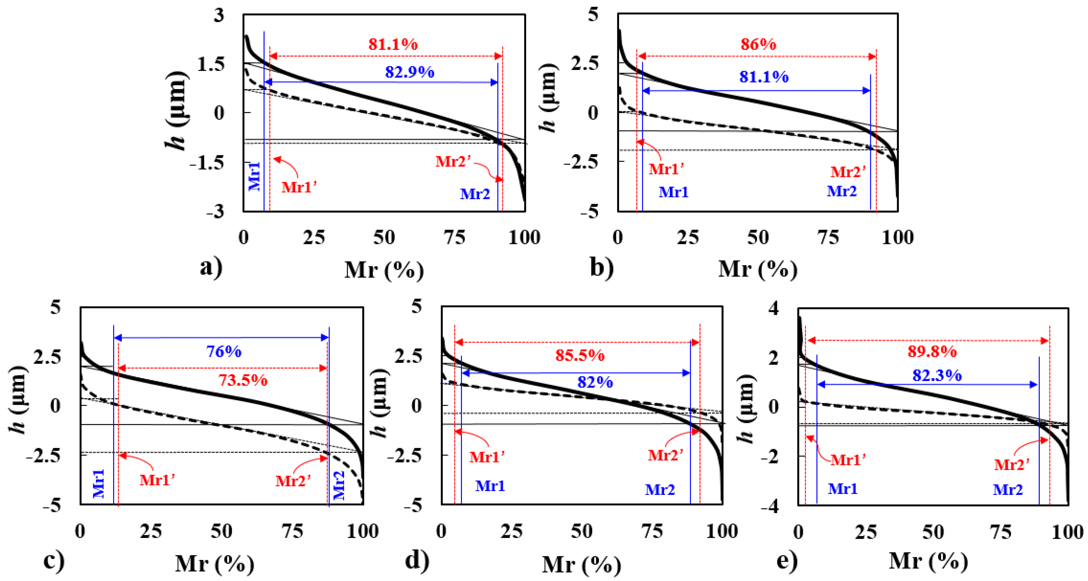
3.1.2. Abbott Curves

The Abbott curves of various surfaces, for which parameters describe increases in the material component as a function of the depth of the roughness profile, can be used to evaluate the functional performance of mechanically highly-stressed surfaces (DIN4776-1990). For several metallic sliders of different materials, Abbott curves of surface profiles after wear become smooth, providing a large contact area, as shown in Figure 4. This results in the decrease of contact stress is prone to lengthen the wear life of sliders. Changes in the slopes of the Abbott curves were different for different metallic sliders. Among all the various metallic sliders, the curve of the slider of dural alloy 7075 presented the smallest slope. Parallel locations of the Abbott curves before and after wear are obvious. In addition, the quenched steel surfaces presented a greater degree of bearing ratio (86%) than that of common steel surfaces (81%). The Abbott curve of the slider surface of Q345B steel after wear was mild, and wear loss of surface material was not significant. The Abbott curve of nodular iron QT700 was also fairly flat after wear. A large actual contact area is desired for smooth contact and good wear resistance. After 2830 m wear, Abbott curve of the slider surface of nodular iron was mainly located below the baseline (90%), a direct result of wear loss of surface material to a certain extent. This shows that the material surface lost its original wear resistance and bearing function.
Power spectral density (PSD), a critical parameter for characterizing both the asperity amplitudes and spacing [30], is obtained by Fourier decomposition of the surface profile into its sinusoidal component spatial frequency. Power spectrum maps of the surfaces of the metal sliders before and after wear are shown in Figure 5. Note that power spectra of contact surfaces for different materials have a significant difference before and after wear.
It can be seen that fractal dimensions of the different slider surfaces show clear difference after wear. Power spectrum presents that the wear surfaces of different materials show the fractal characteristics. After wear test, the fractal behavior of the contact surface has the extent of the decrease, especially for 45 steel (without heat treating) surface with the lower hardness. On the whole, the double logarithmic curves of the power spectrum show a certain similarity, which is consistent with the essential characteristics of fractal. It is of scientific significance for the surface characterization by scale-free fractal analysis. In addition, fractal behavior is shown on the contact surfaces for different sliders before and after wear. For instance, soft 45 steel surfaces with a clear variation tend to be consistent with the fractal characteristics. Differently, variation of 7075 duralumin surfaces is rather small and seems as the roughness parameters. Besides, the contact interfaces are consisted of 7075 sliders and 2A12 vibrators. Similar dissolve mutually theory may be accounted for adhesion, transformation and dissolution as well as the limited wear lifespan.

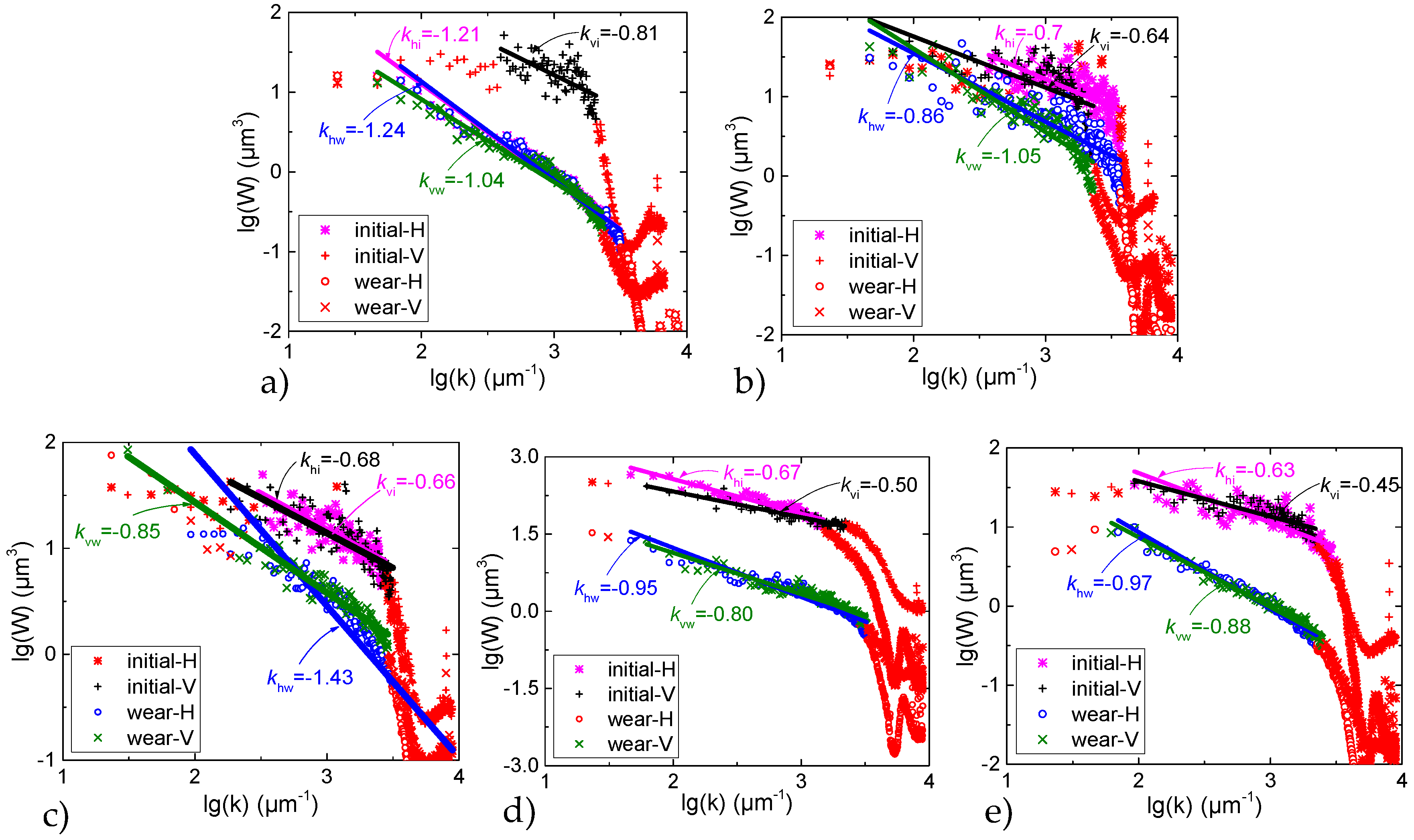
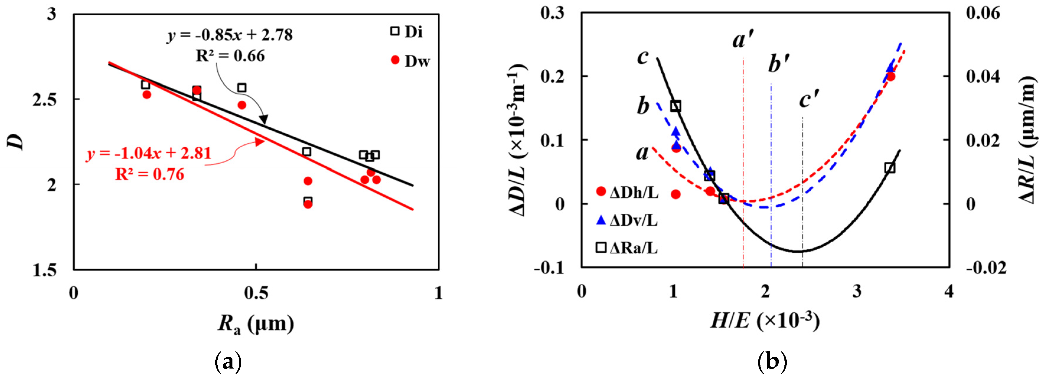
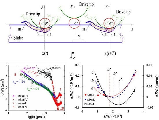
3.1.3. Fractal Dimension

Analysis from different perspectives on surface characterization (i.e., surface roughness parameters and fractal dimension) of metallic surfaces after sliding wear under ultrasonic vibration has been illustrated in the preamble. Herein, average roughness parameter and fractal dimension of the surfaces of different materials are linear fitting, as shown in Figure 6a. Correlation degrees between surface roughness and fractal dimension of different working surfaces are different. By taking into account the difference of material properties, the effect of the plastic factor (defined as the ratio of hardness and elastic modulus) on the two former parameters are discussed, as shown in Figure 6b, where Di and Dw are fractal dimensions of working surfaces of sliders before and after wear, respectively; and Dh and Dv are the fractal dimensions of working surfaces of sliders calculated by using PSDF method along the horizontal and vertical directions, respectively. The variation of surface roughness and fractal dimension are found to show a linear approximation, although the coefficient of determination R2 have low values for the initial and wear surfaces of sliders. In addition, the fractal dimension of the surface is affected by the roughness. The surface roughness is larger, and the fractal dimension is smaller. For different couples with different hardness and elastic modulus, the variation of fractal dimension and surface roughness obey the parabola curves, but asynchronous change. Note that the change of surface roughness is greater than that of fractal dimension in the unit wear length.

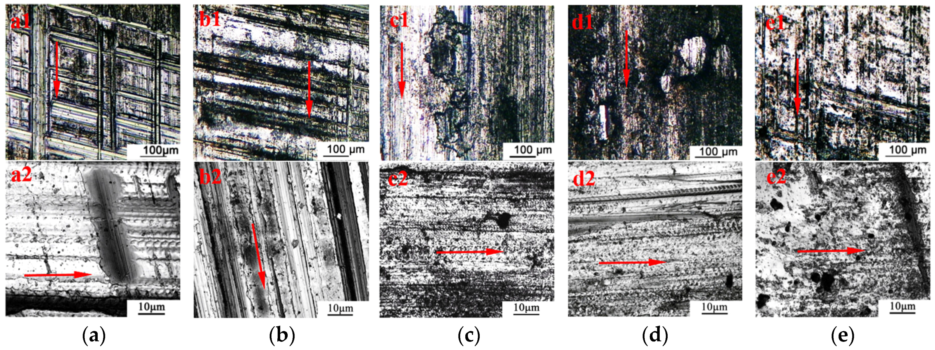
3.2. Wear Topography

Wear topography of metallic sliders are provided in Figure 7. Regardless of the wear scars at the sub-millimeter level (upper, ×100) or micrometer level (lower, ×1000), differences of wear traces for various metallic sliders in contact with the 2A12 material vibrator in the linear ultrasonic motor are quite obvious. Notably, some hierarchical traces of reticular pattern are shown on the contact surface of the 45 steel slider (Figure 7a). Considering the last working operation in this study before the wear experiment was finish milling, the transverse hardening zones are derived from the final machining processes. After friction and wear, hardening zones are exposed as stripes. The hierarchical and longitudinal grooves along the sliding directions originated from the plowing effect of the asperities of the driving tip and free particles.
Result of macroscopic sliding friction between the vibrator contacting the longitudinal distribution of reticular grooves originated from the running rail, and were relatively static. The contact surface was not smooth enough. The hierarchical grooves in the vertical direction appeared on the slider surface caused by sliding friction. The micro level of wear scars is characterized by scaly 5 μm wear traces along the sliding direction, caused by the cumulative effect of intermittent contact and periodic deformation during the vibrator’s operation. Supposing the equivalent radius of asperity of the vibrator tip is r, then both elastic and plastic deformation occurs at the effective surface domain within the slider surface. The excitation frequency of the applied voltage in this experiment was 39.8 kHz, and contact period was about 2.5 × 10⁻⁵ s. The speed of the motor was about 200 mm/s under the voltage amplitude of 150 V. The distance between two adjacent scaly pits nearly equal to the sliding distance of the given asperity during dynamic contact between the slider and the vibrator tip.
The quenched 45 steel slider showed a high level of hardness (HBS294), and higher contact stiffness which generated slight plastic deformation and few shallower grooves on the surface of the heat-treated slider. Consequently, surface wear of the slider of the quenched 45 steel was fairly mild. Compared to the initial damage of machining, the wear traces and grooves of the sliding friction were relatively few, and not serious. Changes in surface roughness before and after wear further demonstrate this. As shown in the micro-level map, some regular scales appeared on the surface of the metallic slider. The size of scales and their distances apart (3 μm) were relatively smaller than those of 45 steel slider. Wear traces of slider surface at the extreme location are shown in Figure 7b. As shown, a cylindrical hole with a width of 80 μm was exposed, along with a few parallel grooves in front of the hole. Few scattered cracks also appear at the non-contact zone near the plastic hole. It is possible to infer that the hole resulted from accumulation between impact deformation and fatigue failure.
Wear traces of the 7075 aluminum alloy slider surface are shown in Figure 7c. Thin grooves on the slider surface appeared in the direction of sliding friction, plus cracks caused by adhesive wear and fracture. There were no grooves or ridges in other directions aside from the sliding direction, which diverts from the pattern shown by 45 steel prone to work hardening. On the microscopic level, in addition to the groove-like features of plastic deformation and scaly wear traces, fatigue cracks occurred on the contact surface of the aluminum alloy 7075 slider. The length of crack propagation is clear, and the propagation direction is along the sliding direction of the slider.
The grooves on the surface of the Q345B steel slider (Figure 7d) along the sliding direction are not so obvious. Unlike metal guides of other materials, abrasive particles appeared on the surface of the Q345B slider. The migration of abrasives typically forms three-body abrasion, as abrasives slide and roll on the contact surface along the sliding direction and the increase the wear loss while decreasing friction. These mechanisms are very undesirable as far as the friction material requirements for ultrasonic motors. In addition, wear particles embedded into the slider surface acted as temporary asperities, causing wear loss in the driving tip. At the microscopic level (×1000), scaly tracks also appeared on the surface of the Q345B slider. The superposition effects of periodic contact of the asperities in driving tip and slider formed scales both in the vertical direction and the horizontal direction. The repetition rate of dynamic contact was higher, and the scale traces were finer.
Wear morphology of the nodular cast iron slider is shown in Figure 7e, where fine and sparse grooves appear on the slider surface along the direction of movement of the slider. Oblique scratches caused by machining are also clearly visible on the slider surface. In addition, plowed grooves on the contact surface are fine and sparse, i.e., the plastic deformation degree was fairly low. Notably, there were no obvious micro-cracks or fatigue traces formed on the contact surface of the cast iron slider. Therefore, as far as basic mechanisms of wear loss are concerned (i.e., plastic deformation and fatigue fracture), nodular cast iron can be considered suitable friction materials for SWUMs.

3.3. Generation Mechanism of Smooth Surfaces

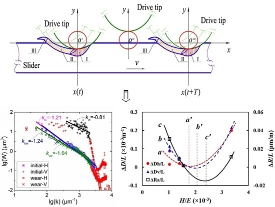
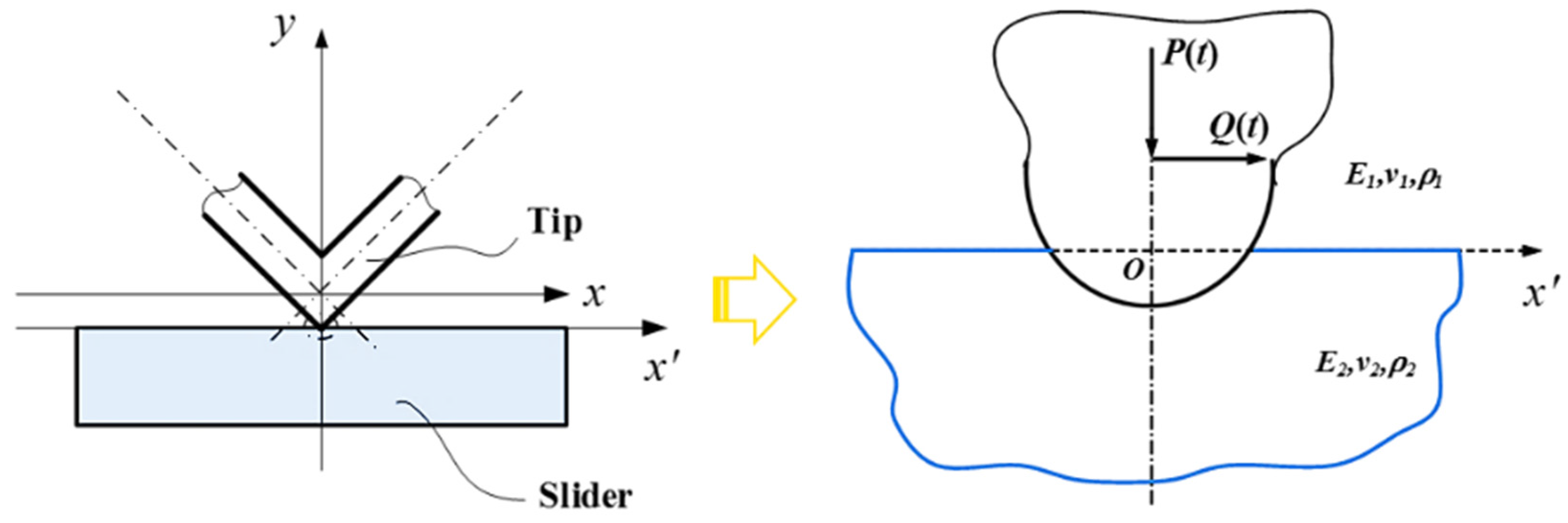
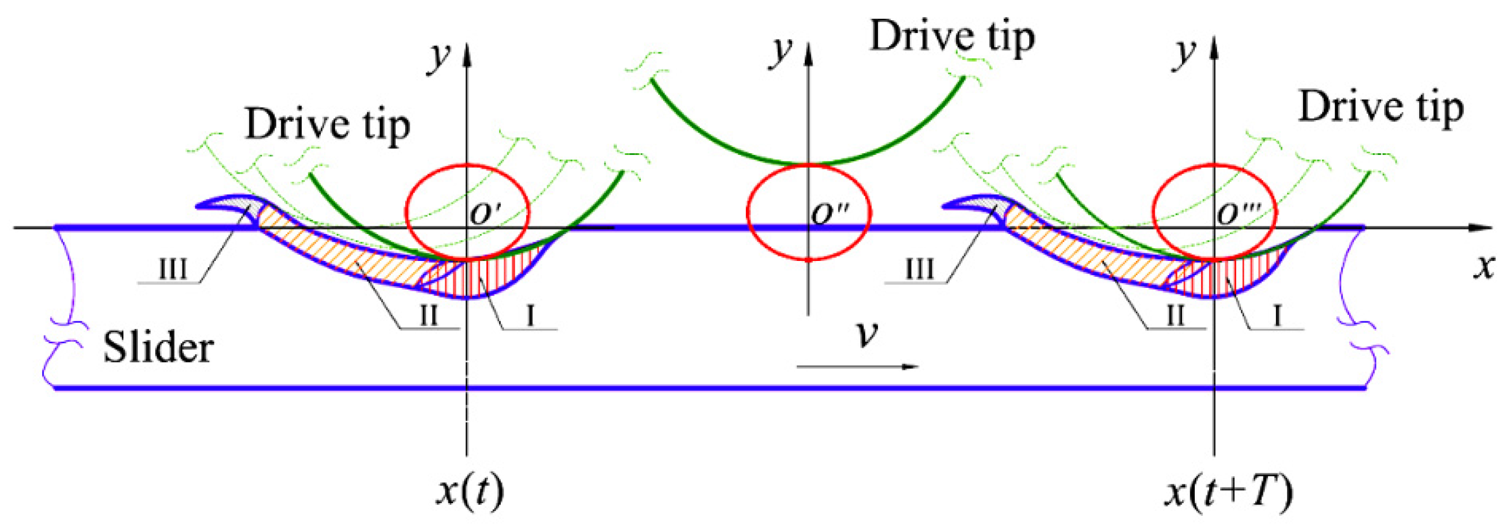
3.3.1. Spatial Envelopes with Rolling-Sliding Friction

As shown in the aforementioned section, there are manifest differences among the various friction pairs of metallic materials related to contact characteristics. For a cylindrical driving tip in contact with an elastic metal slider, contact characteristics including contact width, indentation depth, and contact stresses are available for Hertz contact [35,36,37]. A sketch of a contact model is shown in Figure 8.
As the slider is driven by the vibrator tip, vibration displacements of the driving tip in the horizontal direction and vertical direction are simple-harmonic functions of time. These sinusoidal (and/or cosine) functions result in the type of elliptical locus present, which affects the output performances of an ultrasonic motor. Correspondingly, stresses induced by piezoelectric vibration also vary with time. Indentation deformation affects not only the contact characteristics of the vibrator and slider, but also affect the drive efficiency of the ultrasonic motor in entirety. However, if the major semi-axis of the elliptical locus of the vibrator motion is smaller than the indentation depth for a given normal force, material points of the driving tip would be trapped in the static pressure cavity and finally fail to drive slider movement.
Subsurface stresses are not dependent on elastic constants of different metallic materials. Physical and mechanical properties of metallic materials, however, are related to hardness, residual stress, microstructure, and micro defects. In this paper, these issues are not included in analysis. Factually, the stress components along the different axes are variable under the condition of normal dynamic force accompanied by horizontal dynamic force.
Wear modes of sliders are shown in detail above, including adhesive wear [38], a crucial consideration especially for metallic materials. As is commonly known, friction pairs consisting of two metals with high miscibility are prone to atomic exchange due to plastic deformation and friction heat, which result in adhesion. For instance, the 2A12 driving tip is prone to adhere with a slider made of dural alloy 7075. Dynamic contact between the driving tip and the slider is intermittent and periodical. Stresses induced by piezoelectric vibration both in vertical and horizontal directions vary with time over a certain period. The contact surface of the driving tip and the slider under intermittent impact, dynamic rolling, and sliding friction are accompanied by plastic deformation (as seen in Figure 9). The impact zone is formed by vertical displacement of the driving tip and resultant compression stresses. Decrease in contact stress, accompanied by an increase in indentation depth before the driving tip reaches the extreme position of the elliptical locus along the semi-minor axis, results in an increase of the contact area with time, or vice versa. The former contact process can be regarded as an extended contact and the latter as a reduced contact. Rolling friction emerges when the driving tip begins to catch the contact zone, caused by dynamic forces and changes of the moment of momentum.
Transmission and equivalence of piezoelectric forces of V-shape vibrator along the axis of Langevin transducers is shown in Figure 10. The crossing point of action lines of two Langevin transducers along the axis lies at point O. The contact area of the driving tip and slider extends from point O’, altogether defined |OO’| = d, dependent on the structure of the driving tip. Based on the equilibrium of forces, it is possible to define the equivalent loads at the contact point as FL’ and FR’. Additionally, the moment of couples are presented. Notably, M1 = F1·d·sinα and M2 = F2·d·sinα, i.e., M = M1 + M2 = (F1 + F2d·sinα, where the critical issue is that the piezoelectric loads of Langevin transducers along the orthogonal axes are variable with time. The moment of a couple is not zero, and rolling occurs immediately (Figure 10). Impact contact results in fatigue and fragmentation of contact zones, and rolling friction causes grinding effects resulting in a decrease in surface roughness. 2A12 is the softest metal among the metallic materials studied here, yet 2A12 alloy driving tip still destroy slider contact surfaces through the compression-tension stresses induced by piezoelectric vibration.

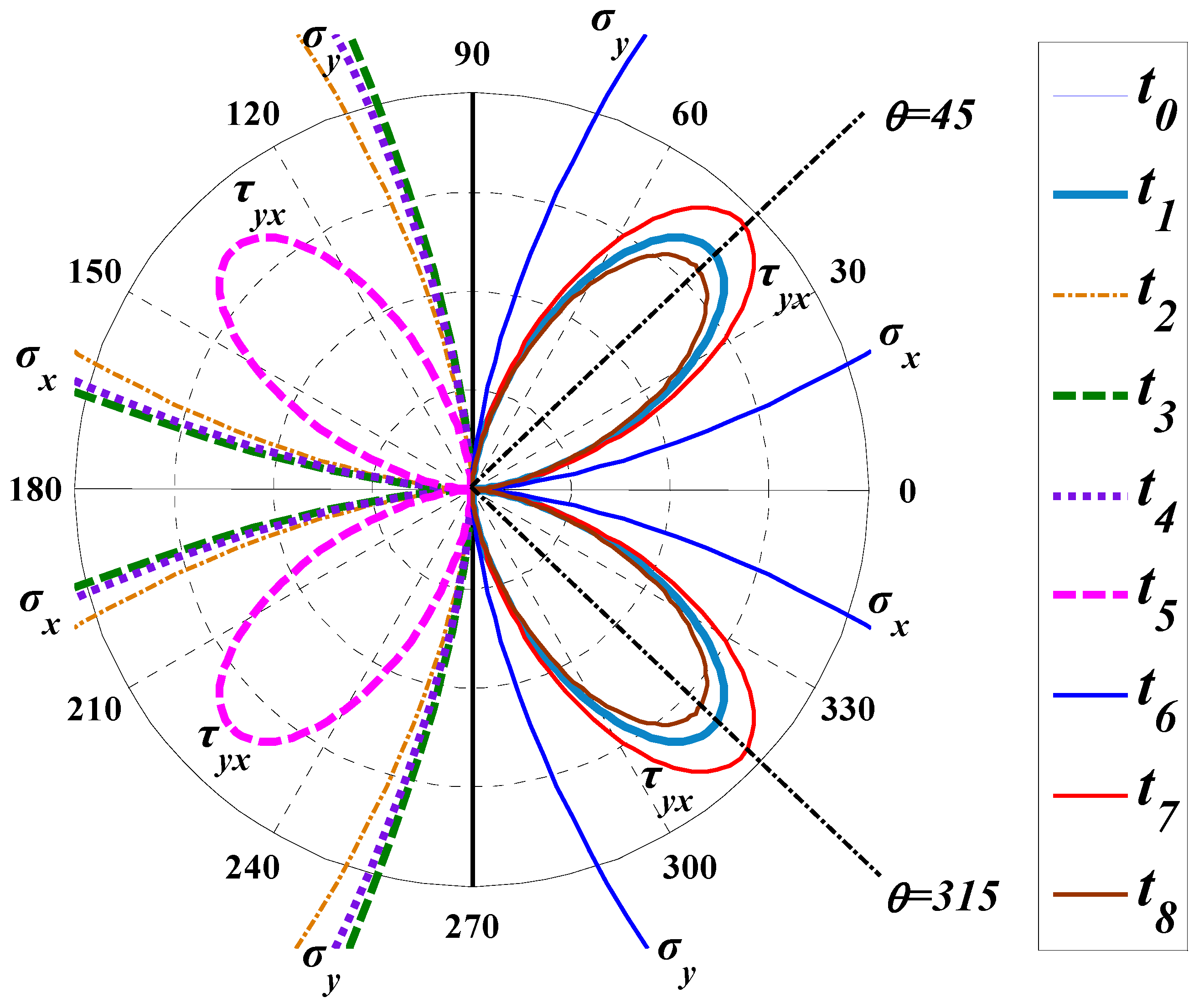
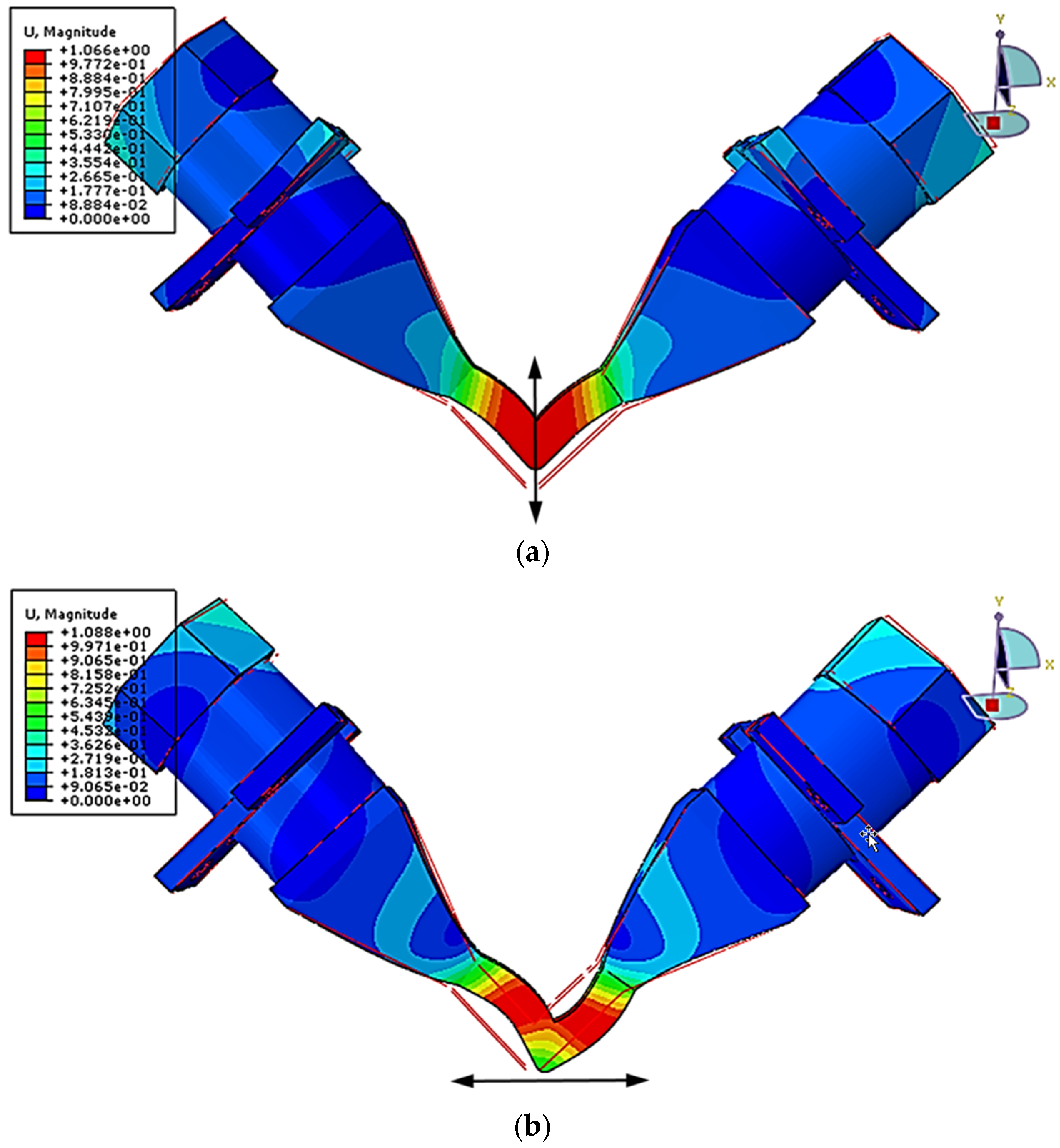
3.3.2. Temporal Stresses of Dynamic Contact

As discussed previously, the elliptical locus of the material point of the driving tip consists of the vertical and horizontal displacements at the microscopic level. The normal and tangential forces induced by piezoelectric vibration of the driving tip vary with time during the operation of an ultrasonic motor, which can be expressed by Equation (4) without considering friction action. Dynamic forces at several typical moments in a contact period are characterized as shown in Figure 11.
{ P ( t ) =   F 0 m ω 2 cos ( k x ) [ A 2 cos ( ω t ) cos α + A 1 sin ( ω t ) sin α ] Q ( t ) =   m ω 2 cos ( k x ) [ A 2 cos ( ω t ) cos α A 1 sin ( ω t ) sin α ]
The stress states of the contact surfaces of sliders vary as normal and tangential forces change. Such types of concentrated forces arise the resultant stresses after the Flamant solution (1892) and provide relations of the stresses (σx, σy, and τyx) and displacements in a linear elastic wedge loaded by point forces at its sharp end. According to classical contact mechanics [37], the composition stresses produced by a concentrated normal force P and a concentrated tangential force Q per unit length distributed along the z-axis can be expressed as follows:
{ σ x = 2 π r cos θ ( P ( t ) sin 2 θ + Q ( t ) cos 2 θ ) σ y = 2 π r cos θ ( P ( t ) cos 2 θ + Q ( t ) sin 2 θ ) τ y x = 2 π r sin θ cos 2 θ ( P ( t ) + Q ( t ) )
For quantitative analysis of the stresses, the abovementioned three kinds of stresses are present in Figure 12 for different moments. Frequencies of dislocation motion and cyclic loading (40.5 kHz) are mismatched, thereby increasing the formation of irreversible plastic deformation, which causes the contact surfaces of sliders’ temperature to rise and heighten internal friction, accelerating crack initiation and propagation. Stress components on the contact surface of sliders also vary with time. During the launching phase of the driving tip, given the normal force applied on the contact surface is equal to zero, only tangential force affects the stress state of the slider. Normal stresses due to the normal force are about zero from t0 to t4. After the t4 moment, normal force gradually begins to affect the stress state. Thereafter, the stress of the contact zone of the slider enters the compression state, in which the majority of the friction drive is generated. In addition, plastic deformation of the contact zone causes dislocation induced by shear stress. From Figure 12, we can see that the maximum of shear stress is not obtained when the normal force gets its maximum value (t6), whereas is the moment of t7. It is because of the contribution of the normal and tangential forces to shear stress is predominant.
An approximation is supposed, that is, when the resultant of the normal force induced by piezoelectric vibration and the pre-load applied on the contact surface is positive we may think that the driving tip and the slider are separated. Therefore, values of the normal forces are reset when the values are positive. The “irreversibility” implied by friction slip suggests that the final state of contact stress will depend on the history of loading and not solely upon the final values of the normal and tangential forces [37]. Actually, to maintain equilibrium with the varied normal and tangential forces, the inner boundary of the contact zone is in accordance with the compatibility condition.
With consideration of dynamic stresses and strains, recall the implication of fretting wear [39] and compare this to the dynamic contact of the driving tip and slider. Specifically, the slider moves along the basement assisted by the driving tip, forming piezoelectric vibration with micrometer amplitudes both in the vertical and horizontal directions; for instance, where ripple or chevron-like marks characterize the surface [40]. Wear mechanisms of driving tips in contact with metal sliders differ from fretting wear mechanisms, however. In this study, wear chips were easily and automatically removed from the contact zone to the non-contact zone of the slider surface, likely a consequence of the lateral vibration and the rolling friction of the driving tip. Carbon in graphite form would in this case diffuse to the contact surface in the friction process and even form a layer of protective film. This type of film creates favorable lubrication to reduce adhesion and prevent metal transfer, possibly why nodular cast iron QT700 sliders showed a favorable performance during running of the ultrasonic motor in this study, exhibiting a stable output performance and durable wear life.
Note that this study examined the wear behavior of the metallic sliders under a load of 1 N, in effect to obtain valuable information regarding preferable friction materials and knowledge of wear mechanisms for SWUMs. In addition, taking impact effects and ultrasonic-frequency deformation under consideration, material analyses including microscopic structure, metallic phase, and composition could offer beneficial data. Serious design considerations are necessary to make standing-wave ultrasonic motors economically viable. Consistent and effective materials working on the contact surface are possibly the most important factor of a motor’s service life, as far as determining whether the ultrasonic motor is worth investing in or ultimately industrializing.

4. Conclusions

Wear behavior of standing-wave linear ultrasonic motors with a V-shaped stator of 2A12 dural alloy and metallic sliders are investigated in this study. Experimental results showed that surface roughness and fractal dimension of the sliders were reduced to varying degrees when different metallic materials were used. Several fundamental factors cover material properties (such as elastic modulus and hardness) and loading conditions are critical for changes in roughness and fractal dimension. Specifically, the reduction can be illustrated as the rolling contact effect between the driving tips and the sliders, caused by the imbalance moment of couple. In addition, wear traces on the contact surfaces account for the combination and accumulation of impact contact, rolling fatigue, and plowing deformation, resulting from the alternate stresses of shearing, tension, and compression due to various normal and tangential forces induced by piezoelectric vibration. These scales are related to the sliding speed of the given sliders during the running of the linear ultrasonic motor. Synthesized analysis suggests that nodular cast iron sliders in contact with dural alloy 2A12 stators show favorable longevity and stability for applications with elliptical vibration, such as standing-wave linear ultrasonic motors.

Acknowledgments

We are grateful to the National Natural Science Foundation of China (Nos. 51305168, and 51175104), and the National Basic Research Program of China (No. 2013CB632305) for providing research funds.

Author Contributions

Yanhu Zhang and Jianjun Qu conceived and designed the experiments; Yanhu Zhang performed the experiments; Jianjun Qu and Hongxiang Wang analyzed the data; and Yanhu Zhang contributed reagents/materials/analysis tools and wrote the paper.

Conflicts of Interest

The authors declare no conflict of interest.

References

  1. Thoe, T.B.; Aspinwall, D.K.; Wise, M.L.H. Review on ultrasonic machining. Int. J. Mach. Tools Manuf. 1998, 38, 239–255. [Google Scholar] [CrossRef]
  2. Moriwaki, T.; Shamoto, E. Ultrasonic elliptical vibration cutting. CIRP Ann. Manuf. Technol. 1995, 44, 31–34. [Google Scholar] [CrossRef]
  3. Kurosawa, M.K. State-of-the-art surface acoustic wave linear motor and its future applications. Ultrasonics 2000, 38, 15–19. [Google Scholar] [CrossRef]
  4. Hemsel, T.; Wallaschek, J. Survey of the present state of the art of piezoelectric linear motors. Ultrasonics 2000, 38, 37–40. [Google Scholar] [CrossRef]
  5. Kumar, V.C.; Hutchings, I.M. Reduction of the sliding friction of metals by the application of longitudinal or transverse ultrasonic vibration. Tribol. Int. 2004, 37, 833–840. [Google Scholar] [CrossRef]
  6. Storck, H.; Littmann, W.; Wallaschek, J.; Mracek, M. The effect of friction reduction in presence of ultrasonic vibrations and its relevance to travelling wave ultrasonic motors. Ultrasonics 2002, 40, 379–383. [Google Scholar] [CrossRef]
  7. Littmann, W.; Storck, H.; Wallaschek, J. Sliding friction in the presence of ultrasonic oscillations: Superposition of longitudinal oscillations. Arch. Appl. Mechanics 2001, 71, 549–554. [Google Scholar] [CrossRef]
  8. Ishii, T.; Matsuo, E.; Nakamura, K.; Ueha, S.; Ohnishi, K. Characteristics of ultrasonic motors driven in a vacuum. Jpn. J. Appl. Phys. 1998, 37, 2956–2959. [Google Scholar] [CrossRef]
  9. Wurpts, W.; Twiefel, J. Analysis of ultrasonic vibro-impact systems with equivalent circuits and the harmonic balance method. Sens. Actuators A Phys. 2013, 200, 114–122. [Google Scholar] [CrossRef]
  10. He, S.; Chen, W.; Tao, X.; Chen, Z. Standing wave bi-directional linearly moving ultrasonic motor. IEEE Trans. Ultrason. Ferroelectr. Freq. Control 1998, 45, 1133–1139. [Google Scholar] [PubMed]
  11. Shi, Y.; Zhao, C.; Zhang, J. Contact analysis and modeling of standing wave linear ultrasonic motor. J. Wuhan Univ. Technol. Mater. Sci. Ed. 2011, 26, 1235–1242. [Google Scholar] [CrossRef]
  12. Senjyu, T.; Yokoda, S.; Uezato, K. Speed control of ultrasonic motors using fuzzy neural network. J. Intell. Fuzzy Syst. 2000, 8, 135–146. [Google Scholar]
  13. Lee, K.J.; Ko, H.P.; Kang, C.Y.; Kim, H.J.; Yoon, S.J.; Nahm, S. A study on the friction and thrust force of the shaft and mobile element in the impact typed piezoelectric ultrasonic linear motor. J. Electroceramics 2006, 17, 499–503. [Google Scholar] [CrossRef]
  14. Zhang, J.; Yao, Z.Y. Friction and wear test device of linear ultrasonic motor and experimental studies. In Proceedings of the 2010 Symposium on Piezoelectricity, Acoustic Waves and Device Applications, SPAWDA10, Xiamen, China, 10–13 December 2010.
  15. Zhao, W.T.; Yao, Z.Y.; Wang, X.N.; Ge, Z.F.; Zhou, S.L. Friction and wear test device of linear ultrasonic motor and experimental studies. In Proceedings of the 2011 Symposium on Piezoelectricity, Acoustic Waves and Device Applications, SPAWDA 2011, Shenzhen, China, 9–11 December 2011.
  16. Yamaguchi, T.; Adachi, K.; Ishimine, Y.; Kato, K. Wear mode control of drive tip of ultrasonic motor for precision positioning. Wear 2004, 256, 145–152. [Google Scholar] [CrossRef]
  17. Archard, J.F. Elastic deformation and the laws of friction. Proc. R. Soc. Lond. Ser A Math. Phys. Sci. 1957, 243, 190–205. [Google Scholar] [CrossRef]
  18. Greenwood, J.A.; Williamson, J.B.P. Contact of nominally flat surfaces. Proc. R. Soc. Lond. Ser. A Math. Phys. Sci. 1966, 295, 300–319. [Google Scholar] [CrossRef]
  19. Nayak, P.R. Random process model of rough aurfaces. J. Lubr. Technol. 1971, 93, 398–407. [Google Scholar] [CrossRef]
  20. Militký, J.; Bajzík, V. Surface roughness and fractal dimension. J. Text. Inst. 2001, 92, 91–113. [Google Scholar] [CrossRef]
  21. Mandelbrot, B.B.; Passoja, D.E.; Paullay, A.J. Fractal character of fracture surfaces of metals. Nature 1984, 308, 721–722. [Google Scholar] [CrossRef]
  22. Majumdar, A.; Tien, C.L. Fractal characterization and simulation of rough surfaces. Wear 1990, 136, 313–327. [Google Scholar] [CrossRef]
  23. Durst, P.J.; Mason, G.L.; McKinley, B.; Baylot, A. Predicting rms surface roughness using fractal dimension and psd parameters. J. Terramech. 2011, 48, 105–111. [Google Scholar] [CrossRef]
  24. Liu, P.; Zhao, H.; Huang, K.; Chen, Q. Research on normal contact stiffness of rough surface considering friction based on fractal theory. Appl. Surf. Sci. 2015, 349, 43–48. [Google Scholar] [CrossRef]
  25. Alcock, J.; Sorensen, O.T.; Jensen, S.; Kjeldsteen, P. Comparative wear mapping techniques. 2. Surface roughness and fractal dimension mapping of tungsten carbide/silicon carbide. Wear 1996, 194, 228–237. [Google Scholar] [CrossRef]
  26. Longuet-Higgins, M.S. A fractal approach to breaking waves. J. Phys. Oceanogr. 1994, 24, 1834–1838. [Google Scholar] [CrossRef]
  27. Stemp, W.J. A review of quantification of lithic use-wear using laser profilometry: A method based on metrology and fractal analysis. J. Archaeol. Sci. 2014, 48, 15–25. [Google Scholar] [CrossRef]
  28. Kurosawa, M.K.; Kodaira, O.; Tsuchitoi, Y.; Higuchi, T. Transducer for high speed and large thrust ultrasonic linear motor using two sandwich-type vibrators. IEEE Trans. Ultrason. Ferroelectr. Freq. Control 1998, 45, 1188–1195. [Google Scholar] [CrossRef] [PubMed]
  29. Asumi, K.; Fukunaga, R.; Fujimura, T.; Kurosawa, M.K. Miniaturization of a v-shape transducer ultrasonic motor. Jpn. J. Appl. Phys. 2009, 48. [Google Scholar] [CrossRef]
  30. Gadelmawla, E.S.; Koura, M.M.; Maksoud, T.M.A.; Elewa, I.M.; Soliman, H.H. Roughness parameters. J. Mater. Process. Technol. 2002, 123, 133–145. [Google Scholar] [CrossRef]
  31. Nečas, D.; Klapetek, P. Gwyddion: An open-source software for spm data analysis. Cent. Eur. J. Phys. 2011, 10, 181–188. [Google Scholar] [CrossRef]
  32. Ganti, S.; Bhushan, B. Generalized fractal analysis and its applications to engineering surfaces. Wear 1995, 180, 17–34. [Google Scholar] [CrossRef]
  33. Persson, B.N.J. Contact mechanics for randomly rough surfaces. Surf. Sci. Rep. 2006, 61, 201–227. [Google Scholar] [CrossRef]
  34. Ponson, L.; Auradou, H.; Pessel, M.; Lazarus, V.; Hulin, J.P. Failure mechanisms and surface roughness statistics of fractured fontainebleau sandstone. Phys. Rev. E 2007, 76, 036108. [Google Scholar] [CrossRef] [PubMed]
  35. Mijović, B.; Džoklo, M. Numerical model of a hertz contact between two elastic solids. Int. J. Eng. Model. 2000, 13, 111–117. [Google Scholar]
  36. Mahmoud, F.F.; Hassan, M.M.; Salamon, N.J. Dynamic contact of deformable bodies. Comput. Struct. 1990, 36, 169–181. [Google Scholar] [CrossRef]
  37. Johnson, K.L. Contact Mechanics; Cambridge University Press: Cambridge, UK, 1985; p. 448. [Google Scholar]
  38. Bethune, B.; Waterhouse, R.B. Adhesion of metal surfaces under fretting conditions i. Like metals in contact. Wear 1968, 12, 289–296. [Google Scholar] [CrossRef]
  39. Budinski, K.G. Effect of hardness differential on metal-to-metal fretting damage. Wear 2013, 301, 501–507. [Google Scholar] [CrossRef]
  40. Alic, J.A.; Hawley, A.L.; Urey, J.M. Formation of fretting fatigue cracks in 7075-t7351 aluminum alloy. Wear 1979, 56, 351–361. [Google Scholar] [CrossRef]
Figure 1. Schematic representation of a wear tester with a V-shaped vibrator: (a) front view; and (b) lateral view.
Applsci 06 00289 g001
Figure 2. Vibration modes of the V-shape stator of standing-wave ultrasonic motors: (a) Symmetric mode; and (b) anti-symmetric mode (the color system reads the modal displacement of V-shape vibrator).
Applsci 06 00289 g002
Figure 3. Frequency response plots of the V-shape stator. Amplitude and phase of displacements of driving tip in the horizontal and vertical directions (applied voltage: 150 V): (a) horizontal component; and (b) vertical component.
Applsci 06 00289 g003
Figure 4. Abbott curves of working surfaces of the metallic sliders before and after wear: (a) 45 #1 steel; (b) 45 #2 steel; (c) 7075 alloy; (d) Q345B steel; and (e) QT700 cast iron.
Applsci 06 00289 g004
Figure 5. Power spectrum analysis and fractal dimension of the sliders’ surfaces of different metal materials before and after wear: (a) 45 #1 steel; (b) 45 #2 steel; (c) 7075 alloy; (d) Q345B steel; and (e) QT700 cast iron. “H” responds to the measured data in the horizontal direction, which is parallel to the sliding direction of sliders, whereas “V” responds to data of vertical direction, which is vertical to the sliding direction of sliders.
Applsci 06 00289 g005
Figure 6. Illustration of: (a) Relation of average surface roughness and fractal dimension; and (b) comparison of the change rates after wear in the unit sliding distance (1 m).
Applsci 06 00289 g006
Figure 7. Wear traces on the surfaces of different metal guides of: (a) 45 steel; (b) slack-quenched 45 steel; (c) 7075 alloy; (d) Q345B steel; and (e) QT700; (1) metallurgical microscope (×100); and (2) confocal laser scanning microscope, CLSM (×1000); and arrows indicate the sliding direction of the slider.
Applsci 06 00289 g007
Figure 8. Hertzian contact model of the driving tip of a V-shaped vibrator with a cylindrical configuration and metal slider.
Applsci 06 00289 g008
Figure 9. Periodical contact of the cylindrical driving tip and the slider, including three types of contact zones consisting of: (I) impact; (II) rolling; and (III) plastic deformation.
Applsci 06 00289 g009
Figure 10. Transmission and equivalence of piezoelectric forces along the axis of Langevin transducers.
Applsci 06 00289 g010
Figure 11. Dynamic force components in the vertical and horizontal directions for a period of contact.
Applsci 06 00289 g011
Figure 12. Polar coordinate diagram of changing the equivalent stress components due to the concentrated normal force and the concentrated tangential force from the piezoelectric vibration.
Applsci 06 00289 g012
Table 1. Material properties of friction pairs consisting of metal tips and sliders.
Properties2A12457075Q345BQT700
Density (g/cm3)2.857.892.817.877.09
Elastic modulus (GPa)74.220972212169
Shear modulus (GPa)27.382.326.980.764.7
Yield stress (MPa)265355505250420
Poisson ratio0.360.2690.330.310.305
Specific heat (J/(kg·K))460450960450510
Thermal diffusivity (10−6/K)23.811.72412.810.8
Heat conductivity (W/(m·K))44481304847
HBS (MPa)187214/292 *242218262
* HBS292 indicates Brinell hardness of quenched 45 steel. The Brinell hardness values of various metal sliders were obtained through hardness measurement using an HBE-3000A electric Brinell hardness tester.
Table 2. Sliding conditions of ultrasonic motors consisted of metallic tips and sliders.
Material45 #145 #27075Q345BQT700
Preload (N)2222222222
Voltage (V)150150150150150
Frequency (kHz)39.839.839.839.839.8
Mean velocity (mm/s)208130105102101
#1 Common steel; #2 quenched steel. Reciprocated stroke of the sliders is 0.1 m.
Table 3. Changes in surface roughness of metallic sliders surfaces after wear.
ParameterRa/μmRp/μmRv/μmRs/μm
SliderInitialWearInitialWearInitialWearInitialWear
45 #10.640.342.341.34−2.67−2.1718.937.4
45 #20.810.464.121.27−4.25−3.7218.725.3
70750.790.713.181.64−3.65−5.0518.320.7
Q345B0.830.343.391.61−4.71−1.8217.234.5
QT7000.640.203.610.75−3.78−1.6119.348.2
#1 Common steel; #2 quenched steel. For all surface roughness tests the evaluation length was 0.8 mm and the sampling length was 4 mm.

