1. Introduction
Biomolecular probes such as antibodies, aptamers, oligonucleotides, and proteins are one of the fundamental components of biosensors. Surface immobilized biomolecular probes provide the critical interface between the solid surface and the liquid environment containing target molecules [
1]. One method to pattern the probes on solid surfaces is polydimethylsiloxane (PDMS) based micro-contact printing [
2]. Micro-contact printing is used to immobilize various biomolecules such as lipid-bilayers [
3], immunoglobulins G [
4], laminin [
5], and DNA [
6] on solid surfaces. Using the high affinity and specificity of the biotin-streptavidin interaction streptavidin and biotin conjugated bovine serum albumin (BBSA) are micro-contact printed on gold surfaces as probe molecules creating binding sites for other biotin or streptavidin conjugated biomolecules [
7,
8].
One of the patterns preferred in micro-contact printing methods is barcode-like, alternating linear lines. The printed lines are for sensing and the spacing between printed lines can be used for control, the alternating pattern enables diffraction measurements [
8,
9]. Different methods such as atomic force microscopy (AFM) [
4], fluorescence microscopy [
3], and X-ray photoelectron spectroscopy (XPS) [
10] are used to quantify the binding of biomolecules on micro-contact printed lines. These methods are costly and they require bench top equipment and experts.
Micro/nano immunomagnetic beads enable target capture and separation in biosensing applications and due to these important features they are also employed on micro-contact printed lines to transfer target molecules to the sensor surface, and to form sandwich assays and reflective surfaces for laser diffraction measurements [
7,
9].
Cell phone microscopy is gaining in popularity due to being low cost, and the wide-spread use of cell phones [
11]. Lens attachments [
12,
13] or lens free computational [
14] strategies were developed to turn cell phones into optical microscopes. One approach is to attach a spherical ball lens to a cell phone camera to provides magnification and record microscopic images [
15,
16]. Spherical ball lenses are low cost and easy to assemble. In our previous research we showed that a low cost spherical lens provide 3–5 micron resolution but noise is an important demerit; the images acquired by a cell phone microscope have a low contrast to noise ratio (in press, [
17]). We also showed that images recorded with a cell phone can be analyzed using Matlab image processing codes running on cloud servers [
18].
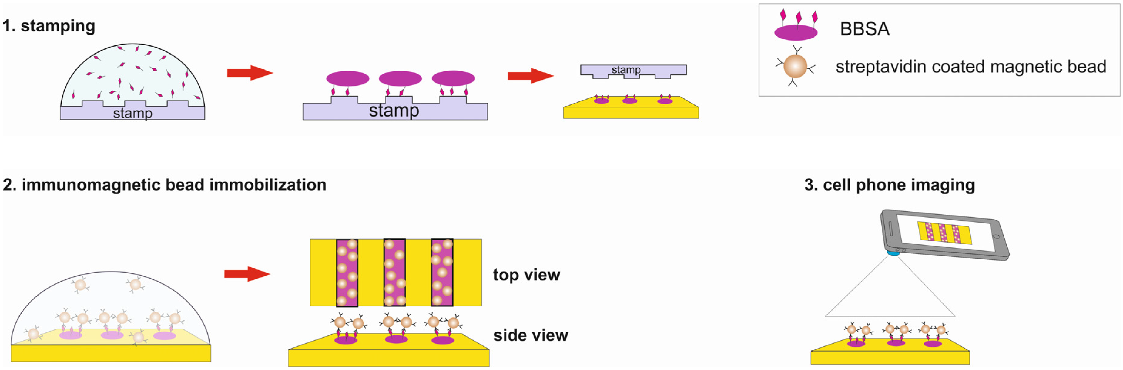
In this paper we use image-processing methods to enhance the images of immunomagnetic beads on micro-contact printed patterns recorded by a cell phone microscopy (
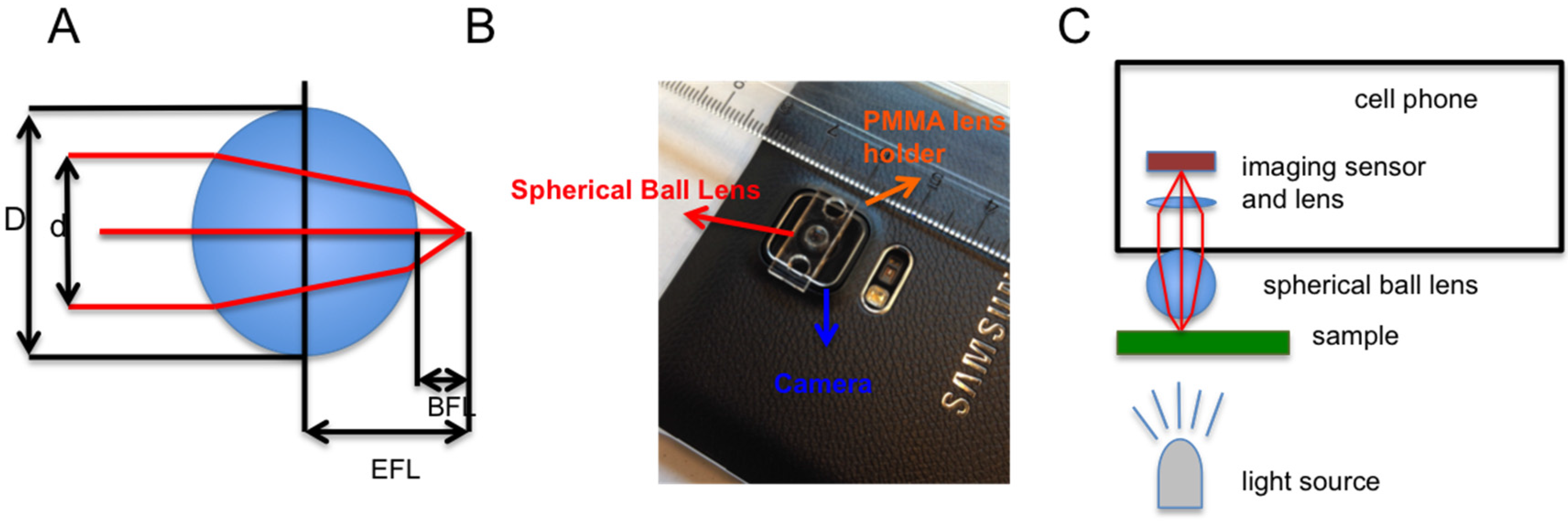
Figure 1). The cell phone microscopy is composed of a Samsung Note S4 cell phone, a borosilicate glass spherical ball lens and a polymethylmethacrylate (PMMA) lens holder (
Figure 2). The image enhancements show that simple cell phone microscopy can be an alternative read-out method to investigate the immunomagnetic beads on micro-contact printed lines. The image processing methods can help to overcome the limitations of the simple spherical ball lens.
2. Materials and Methods
Streptavidin coated superparamagnetic beads of 1 μm in diameter were purchased from Chemicell (Berlin, Germany). Gold-coated slides, phosphate buffered saline (PBS) and Bovine Serum Albumin were purchased from Sigma-Aldrich (St. Louis, MO, USA). Biotin-coupled bovine serum albumin (BBSA) was purchased from Thermo-Fisher (Waltham, MA, USA). Optical micrographs were recorded using Nikon (Melville, NY, USA) microscope equipped with a charge-coupled (CCD) camera, spherical lens was purchased from BioSpec (Bartlesville, OK, USA), PMMA was purchased from Mc Master Carr (Elmhurst, IL, USA). PMMA was cut with a laser cutter as a lens holder and attached to the Samsung Note S4 cell phone with double sided tape (
Figure 2).
The PDMS stamp that contains a 20 μm of alternating lines was first cleaned; washed in ultrasonic bath with 70% ethanol and rinsed with 70% ethanol followed by DI water. Later stream of nitrogen gas was used to gently dry the stamp. The gold chips of size 8 × 4 mm were prepared by first cutting the gold-coated glass slides, cleaning with ethanol and DI water followed by drying with nitrogen gas. The PDMS stamp was inked with 2 mg/mL of BBSA and BBSA solution was left on the stamp for 15 min before removing the excess solution using a wick of a tissue paper from the stamp. The stamp was again dried using a gentle stream of nitrogen gas. Then the stamp was brought into contact with the gold chip and a small force was applied to make a contact between the two surfaces. After waiting for 1 min, the stamp was removed and the gold chip was rinsed gently with PBS to remove the unbound BBSA. To passivate the rest of the surface that had no BBSA, the gold chips were covered a solution of BSA (1 mg/mL) and incubated for 2 min before washing with DI water to remove the unbound BSA.
The gold chip containing the BBSA pattern was incubated with various concentrations (0.0335 mg/mL, 0.067 mg/mL, 0.67 mg/mL and 6.7 mg/mL) of streptavidin coated magnetic beads. After 20 min of waiting, the gold chip was washed with DI water and dried. Then the images of gold chips with immobilized streptavidin coated magnetic beads were recorded using the Nikon optical microscope and the cell phone microscopy (
Figure 2).
The Samsung Note 4 cell phone is equipped with a 16-megapixel (5312 × 2988) camera composed of a Sony IMX240 imaging sensor and an f/2.2 lens with a 35 mm equivalent focal length of 31 mm.
The spherical ball lens has a diameter of
D = 3.51 mm and it is made of borosilicate having a refraction index of
n = 1.517. The important parameters of the spherical ball lens were calculated using the formulas in
Table 1, a is optimal aperture radius as explained in [
19]. Another cell phone’s flashlight was used as a light source, and a simple flashlight can be also considered as the light source.
Nikon optical microscope with 10× objective and 10× eyepiece provides 100× magnification and used as a reference imaging system to compare with cell phone microscope.
Image Processing
The images recorded by cell phone microscope based on spherical ball lens have high noise ratio and intensity variations compared to images acquired by Nikon optical microscope and hence requires image processing to enhance the images. The methods available in Matlab’s Image Processing Toolbox (Version R2014b) were used on the images recorded by cell phone microscope, similar steps were reported in [
20]. Briefly first, the images were converted to grayscale and the average filter was applied to obtain a uniform background. Second, the line opening and background subtraction operations of Matlab were implemented. After the image adjustment and morphological dilation operations the images were converted to binary images using Otsu’s method, and calculations on black and white pixels performed. The pixel areas of the printed and non-printed lines were calculated.
3. Results and Discussion
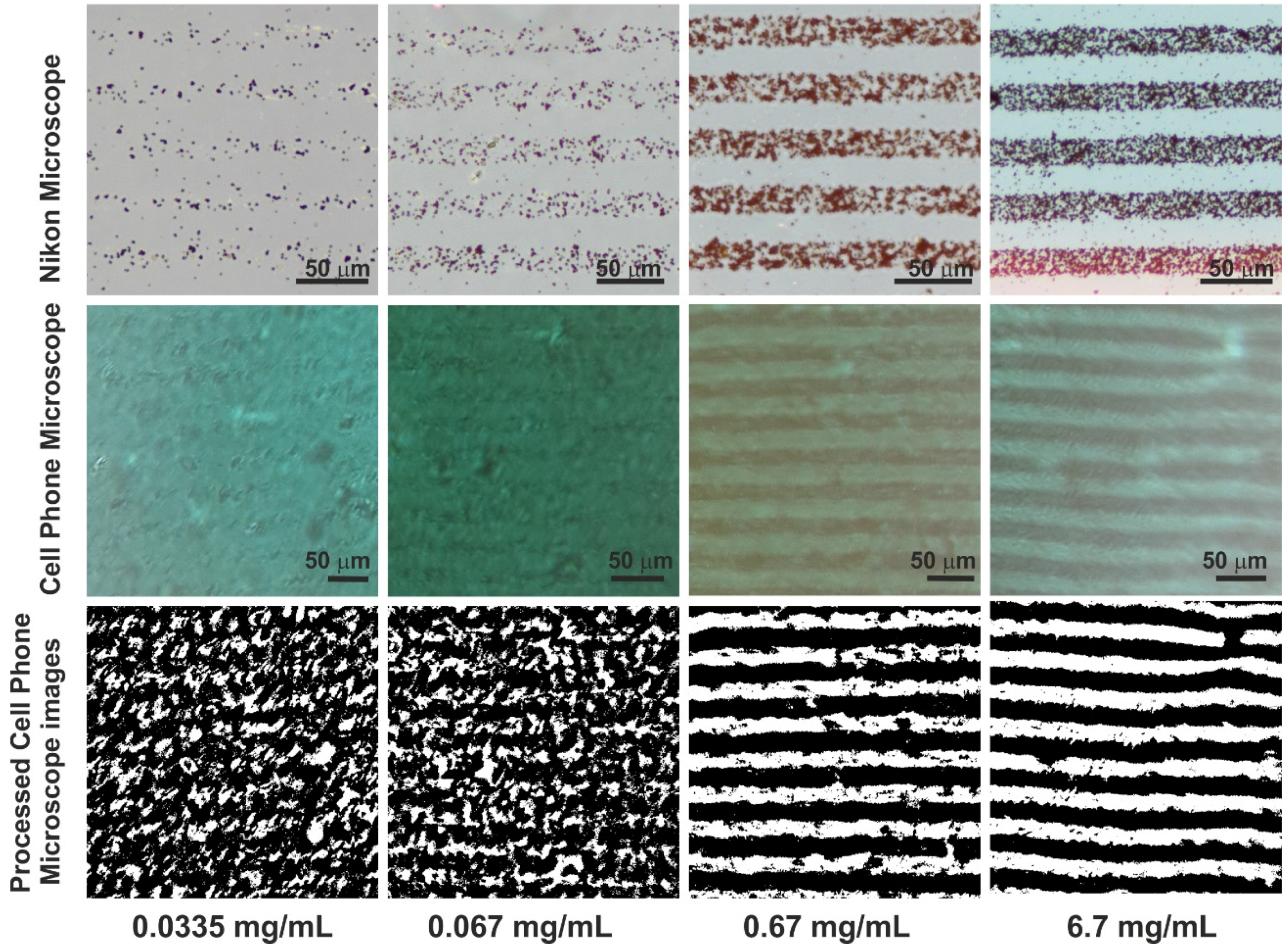
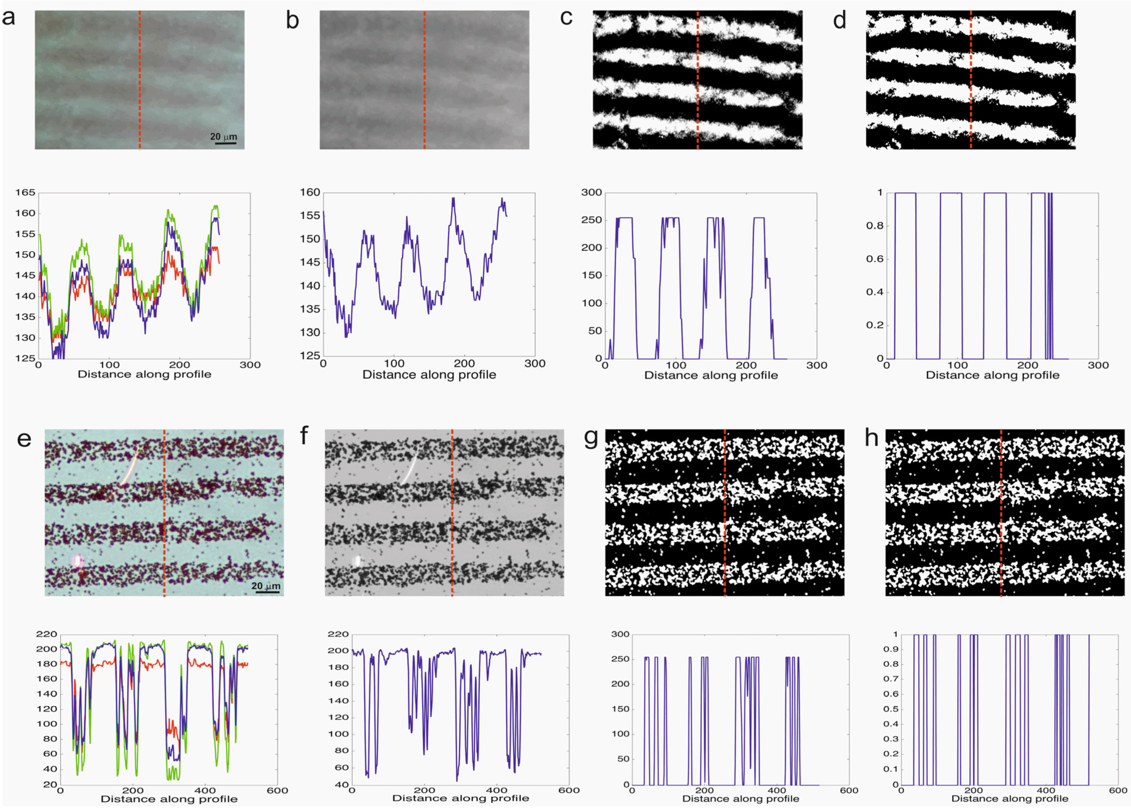
Figure 3 shows the images of the gold chips after the streptavidin coated magnetic beads self-assembled on the micro contact printed BBSA. Optical micrographs of the certain lines were both recorded by both the optical microscope (Nikon) and cell phone microscope (97× magnification). The images, acquired using the ultra-low-cost spherical ball lens, were noisy and the quality of the images was low compared to the images acquired by the reference microscope. In order to analyze the immunomagnetic bead amount on the chips, images were processed using the developed algorithm and converted into binary images. As an indication of the image quality, the variation of pixel intensities along the reference line was plotted. The original image acquired by the cell phone microscope is blurry and not clear thus the intensity difference between the magnetic bead lines and the background is 35 (range is of 0–255); however for the original image acquired by the reference microscope this difference is 150. After the image processing steps the intensity difference between the magnetic bead lines and the background is increased and thus enhanced.
Figure 3 reveals that it is possible to detect single beads using the reference microscope however the cell phone microscope is not able to detect single beads. Instead it can be used to measure groupS of beads which form lines in this case. The white pixels represent the magnetic beads on micro-contact printed lines. The next step is to vary the concentration of the magnetic beads and test the cell phone microscope response.
Figure 4 shows the optical micrographs and processed images for various concentrations (0.0335 mg/mL, 0.067 mg/mL, 0.67 mg/mL and 6.7 mg/mL) of streptavidin coated magnetic beads.
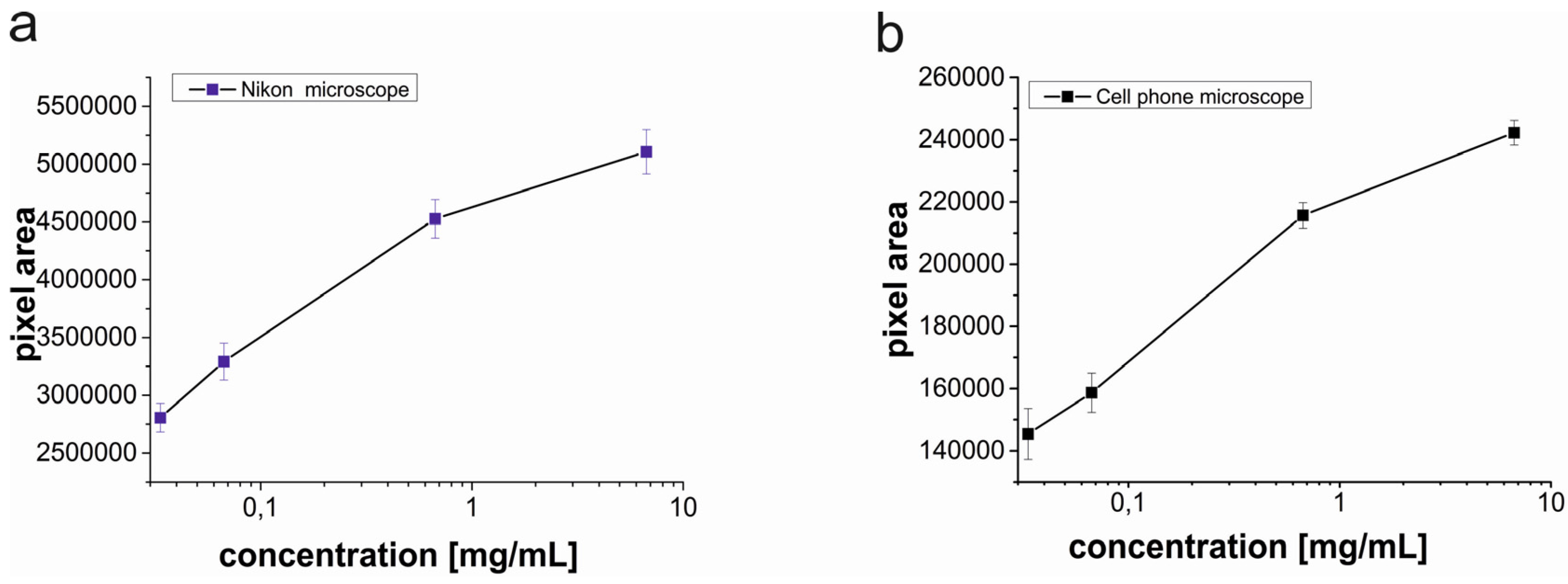
After the cell phone microscope images were processed and the binary images were obtained, the black and white pixel areas were calculated. Images acquired by the Nikon microscope were also analyzed as a reference. The calculated pixel areas of the magnetic beads from the images acquired by the Nikon microscope were approximately 20 times of the calculated pixel areas of the magnetic beads from the images acquired by the cell phone microscope (
Figure 5).
There are mainly two reasons for the 20 fold difference in pixel areas; (1) In the field of view of the spherical ball lens, optical aberrations significantly lower the image quality away from the middle point [
16] for that reason a sub image was cropped from the center area of the acquired image and then the sub-image was processed. However images acquired by the Nikon microscope did not have optical aberrations and the whole images were processed without cropping; (2) The resolution of the Nikon microscope is higher than the resolution of the cell phone microscope resulting in a higher number of pixels in the images. The difference in pixel areas between the microscopes is not important because the width of the micro contact printed lines is 20 μm and this width can be used as a reference to convert pixel calculations to units of micrometers. A conversion ratio for a microscope type, which is the corresponding pixel length for the line width, needs to be determined. Once the conversion ratios are determined by using the processed images, any real length and area of lines can be calculated.
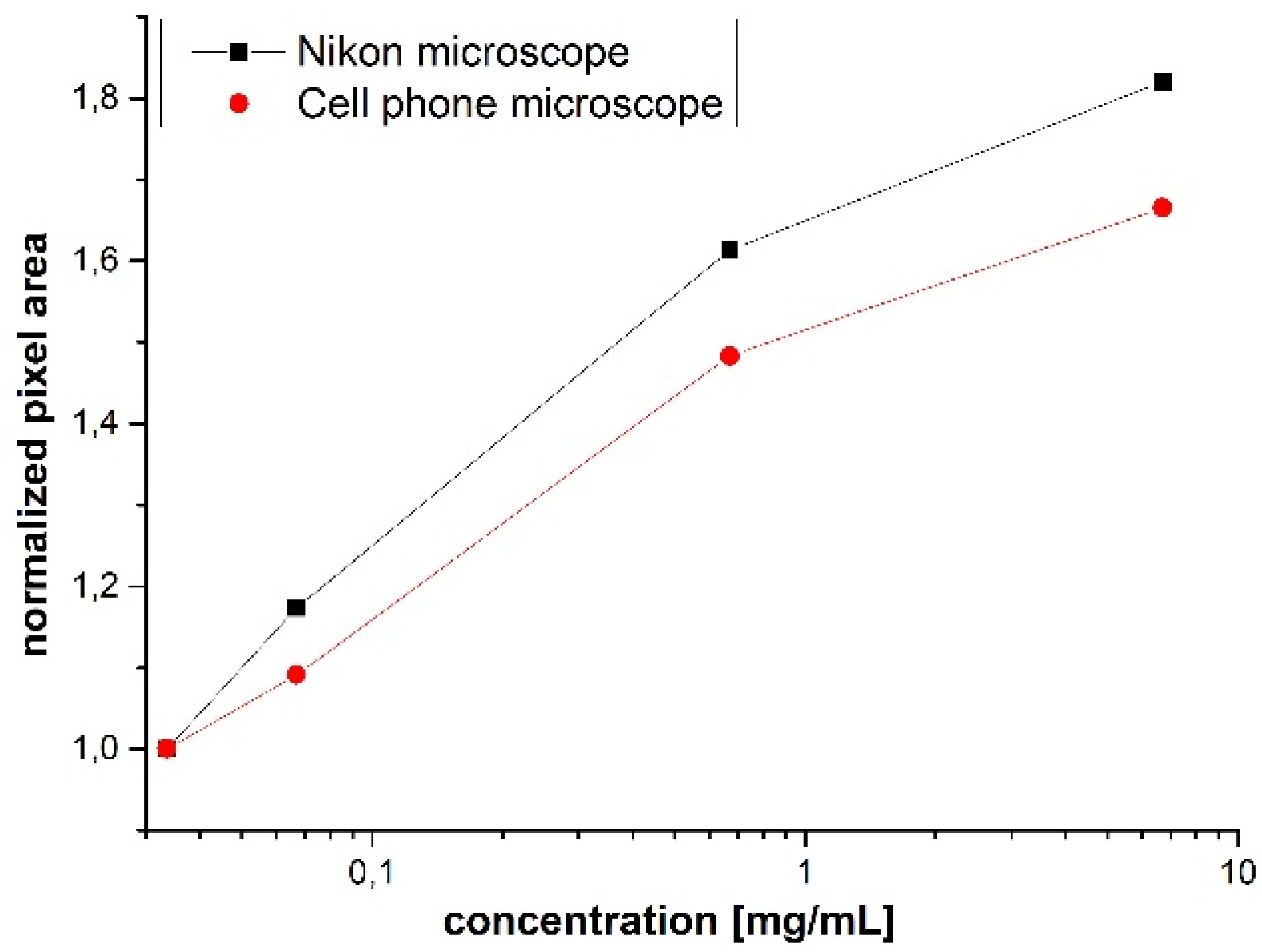
The trends of pixel areas changing with respect to the magnetic bead concentration are similar for both microscopes. To compare the variation of the pixel area with respect to the concentration for both microscopes, pixel areas were normalized by dividing each pixel area by the pixel area corresponding to the lowest concentration (0.0335 mg/mL) of magnetic beads (2805505 for the Nikon microscope and 148036 for the cell phone microscope).
Figure 6 shows the normalized pixel area of the magnetic beads for various concentrations.
The resolution of the cell phone microscope was not high enough to detect a single bead, however the aim of this study was to show that the cell phone microscope with the help of image processing can be used to quantify the group of magnetic beads on the micro contact printed lines.
Figure 6 reveals that the cell phone microscope incorporated with the image-processing algorithm is able to detect concentration variations of magnetic beads on micro contact printed lines.
Biosensors based on micro-contact printed probes and immunomagnetic beads were used to detect biologically significant target molecules such as cancer related folate receptor [
9], and platelet-derived growth factor (PDGF) [
8], and cardiovascular disease related s-adenosyl homocusteine [
7]. In these biosensing applications the number of beads on the surface is proportional to the target concentration. The introduced method in this manuscript can be used to detect and quantify the magnetic bead amount thus a portable, low cost system would be available for the measurements of biologically significant targets.
In order to further test the system’s versatility we used the optical micrograph presented in [
9] for detecting 700 fM folate receptor and calculated the normalized pixel area of the corresponding immunomagnetic beads for 1000 μm
2.
We converted the RGB image to a binary image using ImageJ software [
21] and measured the pixel area of the magnetic beads. In an area of 1000 μm
2, 5057 pixel area represents the amount of magnetic beads that captured 700 fM of folate receptor. The binary images presented in
Figure 4 for 0.067 mg/mL of streptavidin coupled magnetic beads correspond to a white pixel area of 1032 in an area of 1000 μm
2 for the images acquired by the cell phone microscope.
Table 2 shows that the cell phone microscope is capable of detecting biologically significant target molecules and further tests can be conducted to verify the calculations. The capture and binding efficiency of immunomagnetic beads are important parameters that directly affect the sensitivity of the cell phone microscope.
The spherical ball lens used in this study costs less than 10 US cents and the cell phone microscope can be assembled easily in less than a couple of minutes. However the ultra-low-cost spherical ball lens has significant aberrations and creates low quality images. With the help of image processing, the low quality images of immunomagnetic beads captured on micro contact gratings can be analyzed and meaningful data can be extracted. Micro-contact gratings inherently provide differential measurements, and analyzing the alternating printed lines and empty lines can provide information about specific and non-specific binding events. Future hardware and software developments for the cell phone microscope presented in this study can improve the capabilities of the system. It was shown that the sapphire ball lens has a better imaging quality and higher refractive index [
22], which could improve the lateral resolution and decrease the noise. Also by using spherical sensor arrays with a spherical ball lens, uniform spatial resolution [
23] and gigapixel resolution can be reached [
24].
It is evident that the cell phone microscope can produce a better result with bigger-size magnetic beads. Increasing the bead size may affect the binding kinetics, so optimization is needed.
Immunomagnetic beads were also incorporated with micro mechanical transducers [
25] and the developed technique is prone to quantify the amount of immunomagnetic beads on the micro size transducers.
In this manuscript mainly background subtraction, image adjustment and morphological dilation functions were used to process the noisy images. There are also other powerful denoising algorithms such as the Karhunen-Loeve treatment (KLT) [
26] and in order to improve the performance of the cell phone microscope, one of our future goals is to test KLT on the images. A critical issue of the emerging sensors is testing the sensor’s performance in the field [
27]. After improving the image processing algorithms, field tests of cell phone microscope-based sensing will be performed to compare the system’s performance with the commercial systems in terms of the specificity and selectivity.


