Article

Testing of High Thermal Cycling Stability of Low Strength Concrete as a Thermal Energy Storage Material

1
State Key Laboratory of Hydroscience and Engineering, Tsinghua University, Beijing 100084, China
2
Department of Hydraulic Engineering, Tsinghua University, Beijing 100084, China
*
Author to whom correspondence should be addressed.
Appl. Sci. 2016, 6(10), 271; https://doi.org/10.3390/app6100271
Submission received: 25 August 2016 / Revised: 14 September 2016 / Accepted: 15 September 2016 / Published: 22 September 2016

Abstract

:
Concrete has the potential to become a solution for thermal energy storage (TES) integrated in concentrating solar power (CSP) systems due to its good thermal and mechanical properties and low cost of material. In this study, a low strength concrete (C20) is tested at high temperatures up to 600 °C. Specimens are thermally cycled at temperatures in the range of 400–300 °C, 500–300 °C, and 600–300 °C, which TES can reach in operation. For comparison, specimens also cycled at temperature in the range of 400–25 °C (room temperature), 500–25 °C, and 600–25 °C. It is found from the test results that cracks are not observed on the surfaces of concrete specimens until the temperature is elevated up to 500 °C. There is mechanical deterioration of concrete after exposure to high temperature, especially to high thermal cycles. The residual compressive strength of concrete after 10 thermal cycles between 600 °C and 300 °C is about 58.3%, but the specimens remain stable without spalling, indicating possible use of low strength concrete as a TES material.

Graphical Abstract

1. Introduction

Solar energy is a promising sustainable energy source due to its abundant supply and the relatively low environmental impact of its harvesting. However, solar powers are unavailable at night or in poor weather conditions. A thermal energy storage (TES) system is usually integrated with solar power plants to continue production of electricity. TES systems using thermal oil or molten salt as energy storage media are widely implemented, but this type of TES has a disadvantage of high investment cost. Solid sensible heat storage material is an alternative. According to Gil et al. [1], concrete and castable ceramics are the most promising candidates of solid sensible heat storage materials due to their good thermal and mechanical properties and low cost. Strasser and Selvam [2] also carried out a cost comparative analysis between concrete and other heat storage materials and came to the same conclusion. Khare et al. [3] identified some common materials for solid state sensible heat storage in the range 500–750 °C and found high alumina concrete had the lowest cost.
The vast majority of work incorporating concrete as a TES material has been reported by the group led by Laing in German Aerospace Center (DLR). Her group has carried out testing of a concrete energy storage system incorporating an array of embedded heat exchangers and thermal oil as heat transfer fluid, and the energy storage temperature has achieved up to 400 °C [4,5,6,7]. Salomoni et al. [8] presented guidelines for designing a concrete storage module and for its integration into a solar plant, respecting constraints linked both to an adequate solar field operation and to the production system. Skinner et al. [9] developed a high-performance concrete as a heat TES material and conducted high temperature tests in the range of 400–500 °C. In the tests, molten nitrate salt was used as the heat transfer fluid, which was circulated though stainless steel tubes embedded in concrete prisms, to charge the TES system.
In addition to concrete, geopolymer-based materials have been assessed to be potentially employed for storage applications due to their reliable mechanical and thermal properties [10,11,12]. Ferone et al. [13] applied the finite element method to simulate transient behavior of sensible heat thermal energy storage systems using geopolymers. They have taken various aspects into consideration: thermal properties at high temperatures, the actual geometry of the repeated storage element, and the actual storage cycle adopted.
The above mentioned studies are mainly focused on thermal performance of the heat energy storage system during the energy charge and discharge processes. In addition to the thermal characteristics, mechanical characteristics are another key issue for TES material. Structural stability is requested for the TES system at high cycling temperatures. There have been many studies aimed at understanding thermal behavior of concrete at high temperatures, and it was found that there is a reduction for mechanical properties in terms of strength and elastic modulus of concrete when it is exposed to high temperatures. The works are reviewed in the reference [14]. However, effect of thermal cycling on mechanical change of concrete characteristics, which is a major concern for TES system, is not involved in these studies. John et al. [15] carried out thermal cycle tests of concrete and examined their residual compressive strengths which represent the structural stability of concrete.
The purpose of this paper is to investigate the thermal cycling stability of low strength concrete (C20) which is of possible use as a TES material. A series of thermal cycling tests are conducted. Concrete specimens are first subjected to different thermal cycles between 100 °C and 600 °C, and then their residual compressive strengths are measured.

2. Experimental Setup

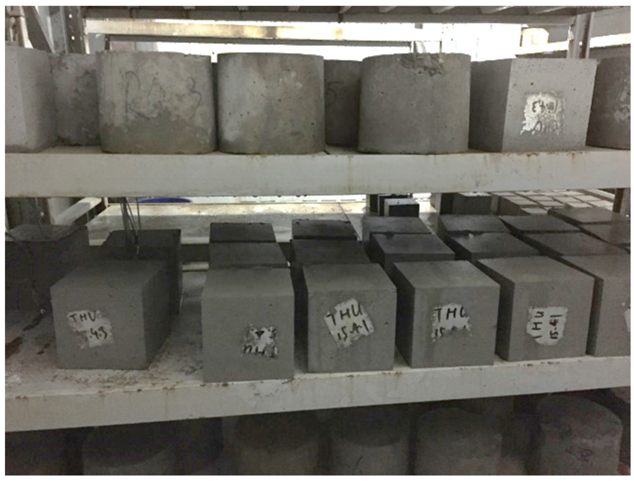
2.1. Concrete Material

Low strength concrete with fly ash, i.e., C20 concrete, is used in this study. Its mixture proportions are given in Table 1. The slump value of the mixture is approximately 95 mm. The well-mixed concrete mixture was poured into molds to form the cubic specimens with the size of 150 × 150 × 150 mm3. The specimens were wet cured for 24 h before being demolded and then cured in a fog room at 23 ± 2 °C for 28 days. The appearance of the concrete specimens is shown in Figure 1.

2.2. Experimental Strategy

An electrical high-temperature furnace with a capacity of heating up to 1000 °C is used to supply thermal cycles on the concrete specimens. Thermal cycles are carried out at temperatures in the range of ambient temperature (25 °C) to the maximal value (400 °C, 500 °C, and 600 °C). Five cycles are considered, and the tests are denoted by 400-25-5, 500-25-5, and 600-25-5, respectively. In order to consider the high-temperature operation condition of the thermal energy storage, the lower temperature during the thermal cycles is selected as 300 °C instead of the ambient temperature. Two cases—one performing 5 cycles and the other 10 cycles—are taken into account. We denote 400-300-5, 500-300-5, and 600-300-5 for the 5-cycle tests; and 400-300-10, 500-300-10, and 600-300-10 for the 10-cycle tests. In addition, non-cycling tests, exposure of specimens to high temperatures of 200, 300, 400, 500, and 600 °C is considered to examine the effect of thermal cycling. Each test case uses three concrete specimens. The test cases are listed in Table 2.
A sufficiently long heating time is necessary to ensure the internal temperature of concrete specimens reaches the expected maximal temperature during the heating process. A finite element (FE) method based heat transfer analysis is carried out to determine a reasonable heating time.
Two concrete specimens, in which temperature sensors are buried, are heated to approximate 400 °C in the furnace. The temperatures of the surface and internal of the concrete specimens are measured, and the variation curves are shown in Figure 2.
A two-dimensional FE model is used to simulate the heat transfer process. The concrete specimen is discretized into 3 × 3 mm2 quadrilateral FE mesh. The measured surface temperature is applied as boundary condition in the simulation. Inverse analysis is carried out according to the temperature curves of specimen 1 to determine the thermal parameters, i.e., the thermal conductivity of concrete and the heat transfer coefficient (HTC) between concrete and air. Figure 3 shows the results of the inverse analysis. It can be found that the calculated internal temperatures gradually approach the measured curve when increasing HTCs from 0.5 to 10 W/m2·°C. Therefore, the thermal conductivity of concrete and HTC are taken as 1.94 and 10 W/m2·°C. The internal temperature of specimen 2 is reproduced using the FE model with the determined thermal parameters. The numerical result shown in Figure 4 is in good agreement with the measured curve, indicating the FE model has sufficient accuracy for heat transfer analysis of the test concrete.
In the numerical modeling, the first heating experiment is considered. The water in the concrete is ignored, which has important influence on heat transfer during subsequent heating of concrete thermal storage structures. However, for the experiment in this work, the heating time on specimens determined using the FE model is acceptable to ensure the internal of the concrete reaching the designed temperature.
According to the FE analysis, the internal portion of concrete specimens may reach 600 °C when exposed at high temperature of 600 °C for 5 h. Therefore, in the thermal cycling experiments the heating period of each cycle is taken as 12 h, including heating time at the maximal and lower temperatures and the transition time from maximal temperature to lower temperature. The heating time in the case of steady-temperature (maximal temperature and ambient temperature/300 °C) is 5 h and the transition time is 1 h.
Specimens are put in the furnace at room temperature. In order to avoid fracture of concrete due to leakage of water vapor trapped into specimens, the temperature of furnace first rises to 350 °C in 1 h and lasts for 1 h, and then is elevated to the maximal temperature (400, 500, and 600 °C) in 0.5 h. The heating scheme for the thermal cycling tests is shown in Figure 5.
After exposure of the concrete specimens to thermal cycling and natural cooling them down to ambient temperature in the furnace, uniaxial compressive strength experiments are conducted as shown in Figure 6.

3. Results and Discussion

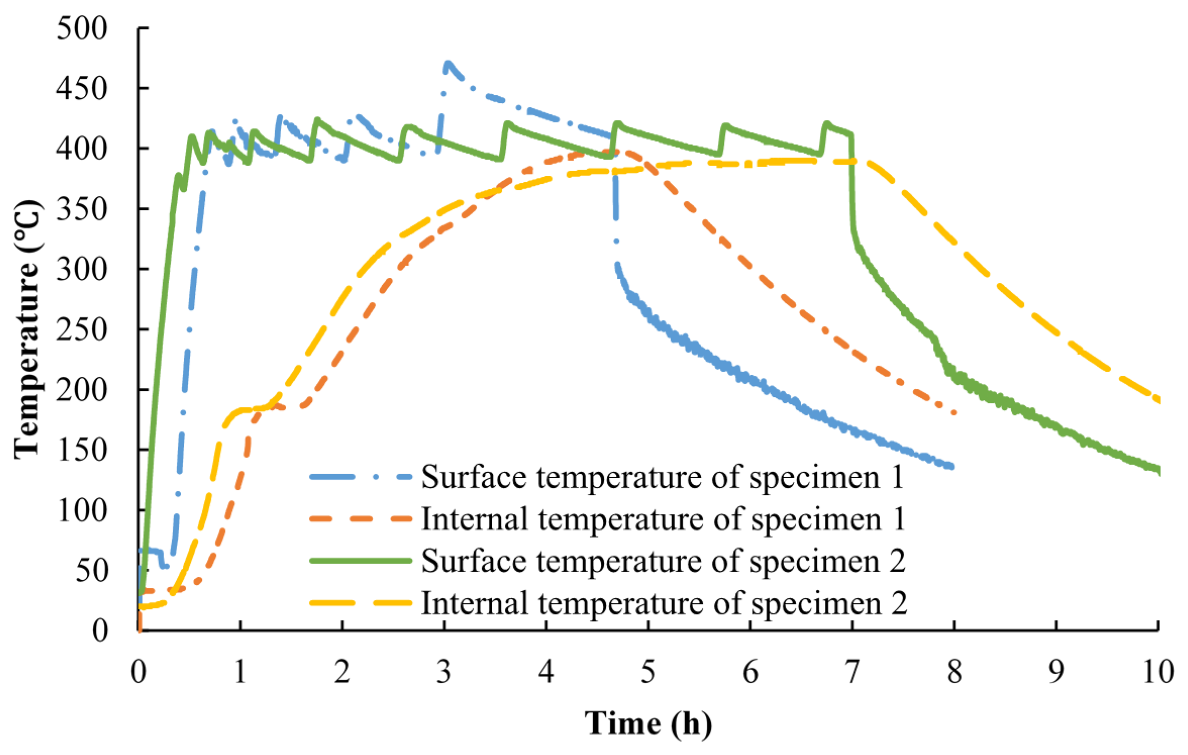
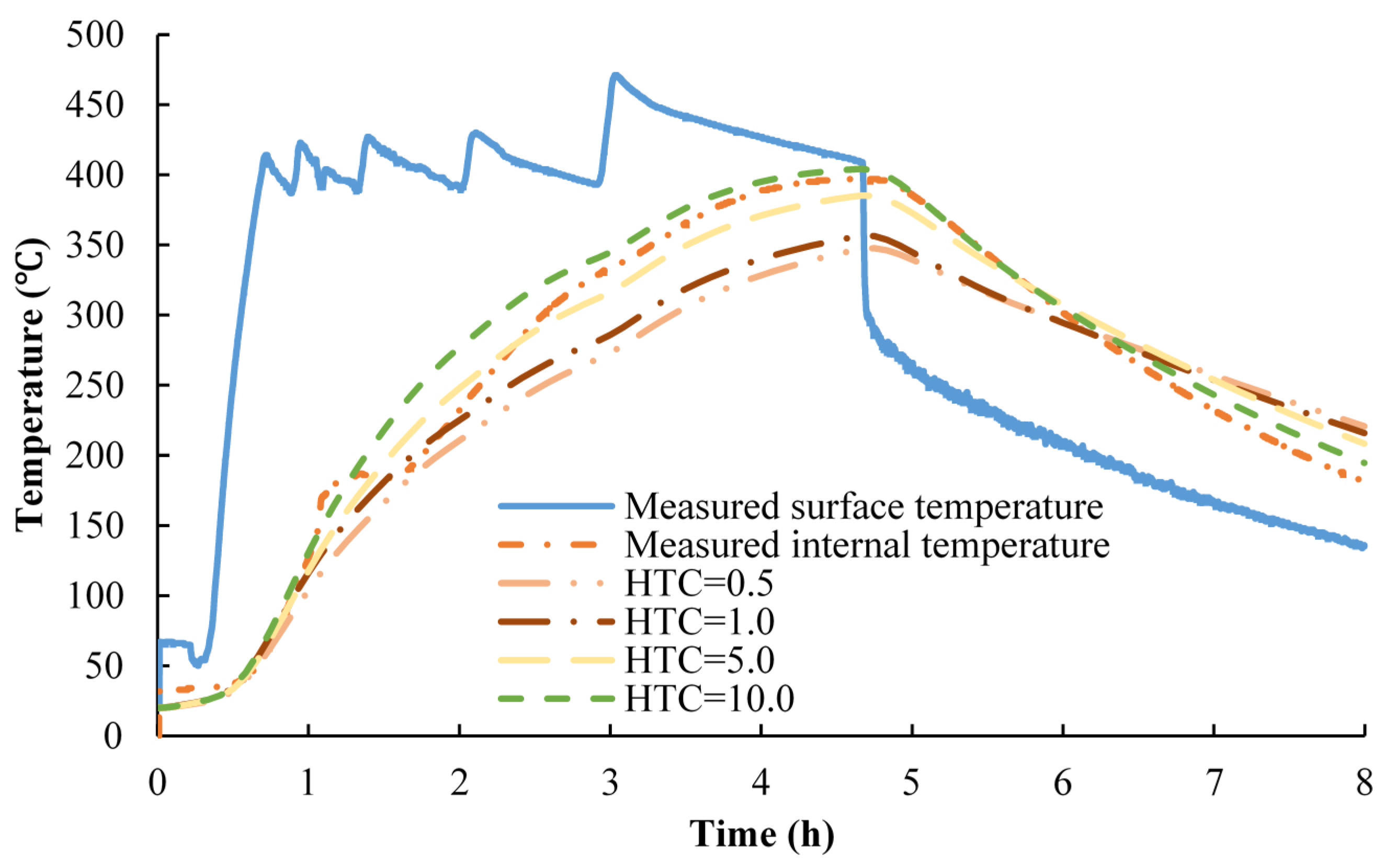
3.1. High Temperature Tests

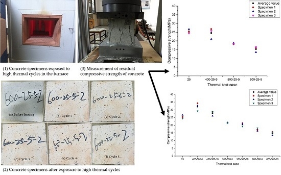
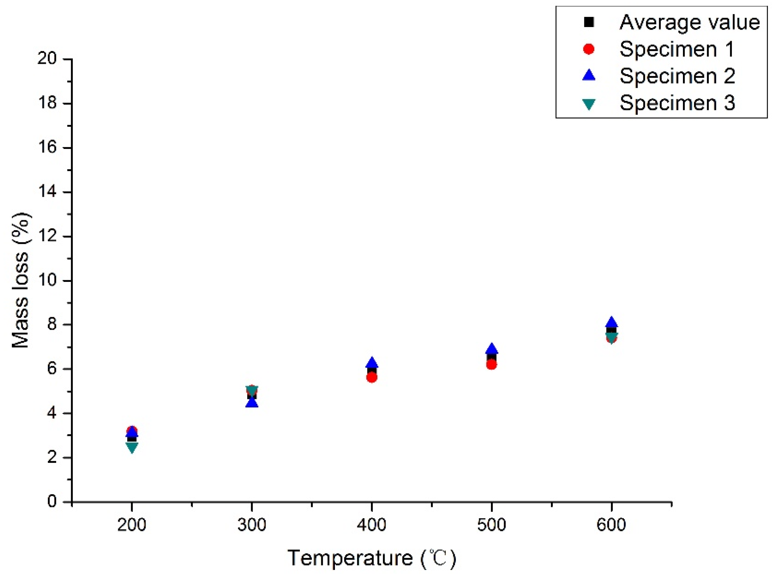
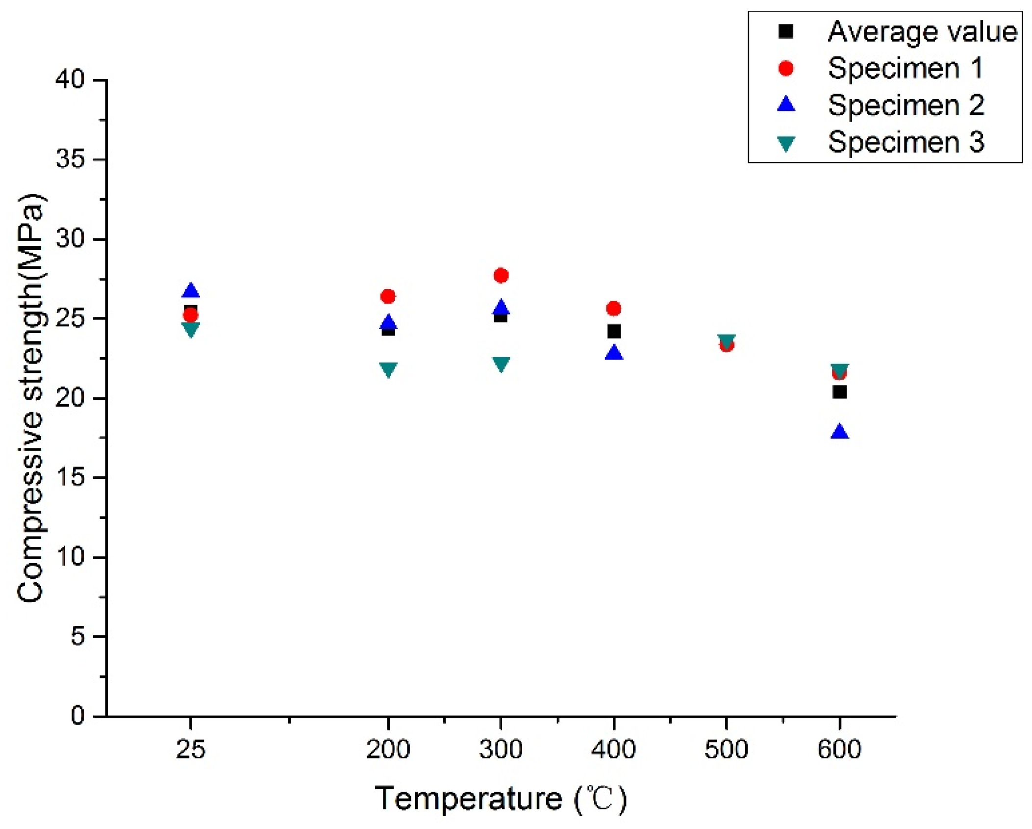
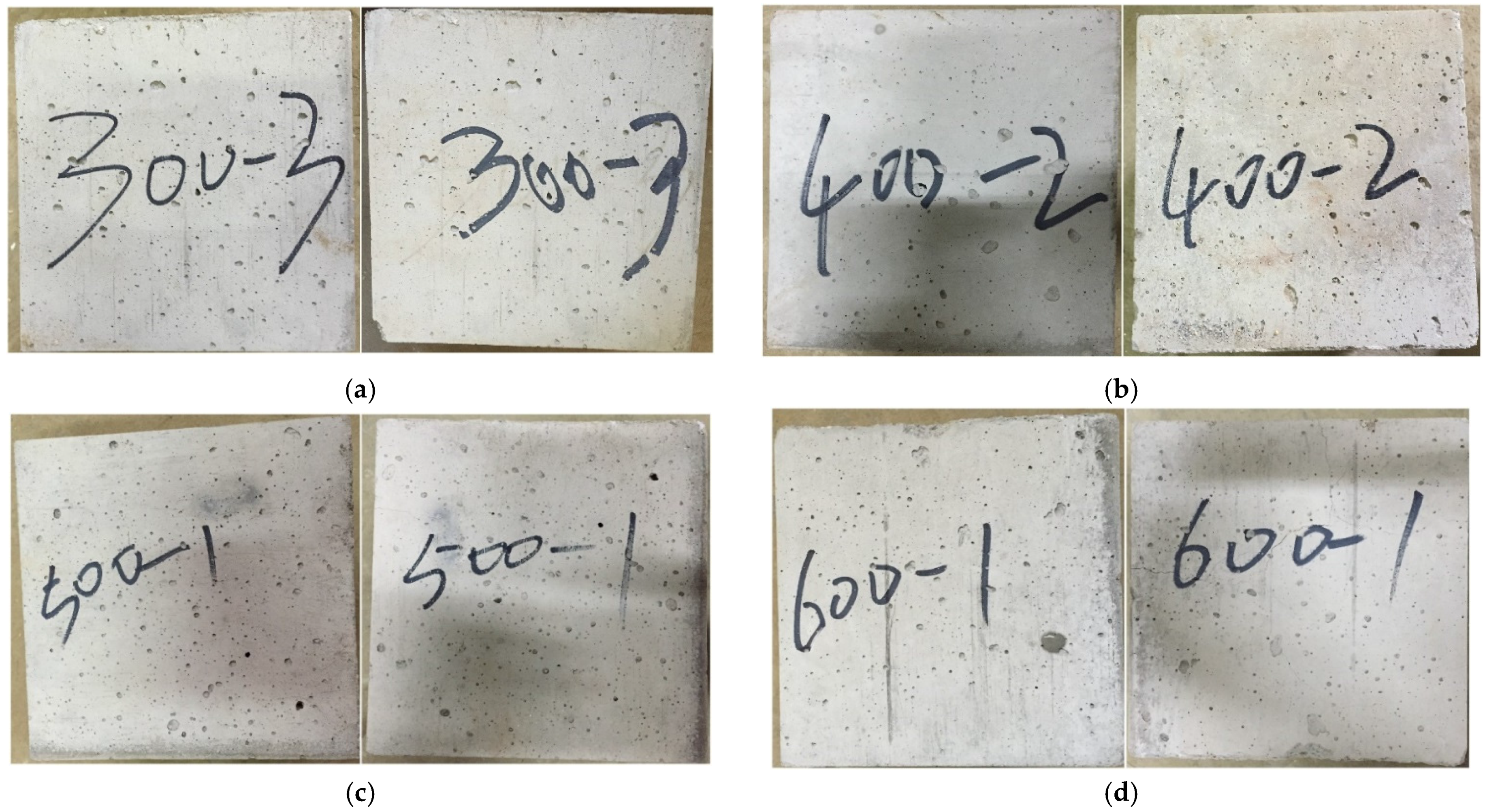
3.1.1. Exposure of Concrete Specimens to High Temperatures

In the non-cycling tests, temperatures of 200, 300, 400, 500, and 600 °C are applied to the concrete specimens respectively. The specimens exposed to elevated temperatures are shown in Figure 7. It can be found that the specimens demonstrate a change of color after exposure to high temperatures. There is no visible crack in the concrete specimens until the temperature elevated to 500 °C. Some micro-cracks form on the surface of the specimens after exposure to 500 °C and more appear at 600 °C. It is considered that different thermal strains for hardened cement matrices and aggregates will produce a stress between them, resulting in the development of the micro-cracks.
Mass loss of the specimens after exposure to high temperatures is shown in Figure 8. The mass loss of three specimens at a target temperature is close. The average value of mass loss for three specimens gradually increases from 3.0% at 200 °C to 7.5% at 600 °C. Since no spalling of concrete occurs, the mass loss is attributed to both leakage of water vapor and thermal decomposition accompanied by release of carbon dioxide.

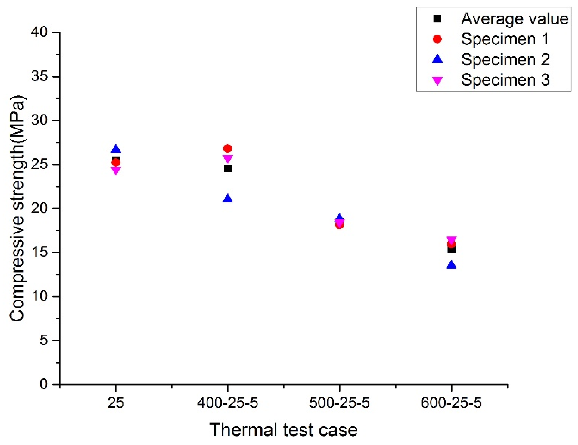
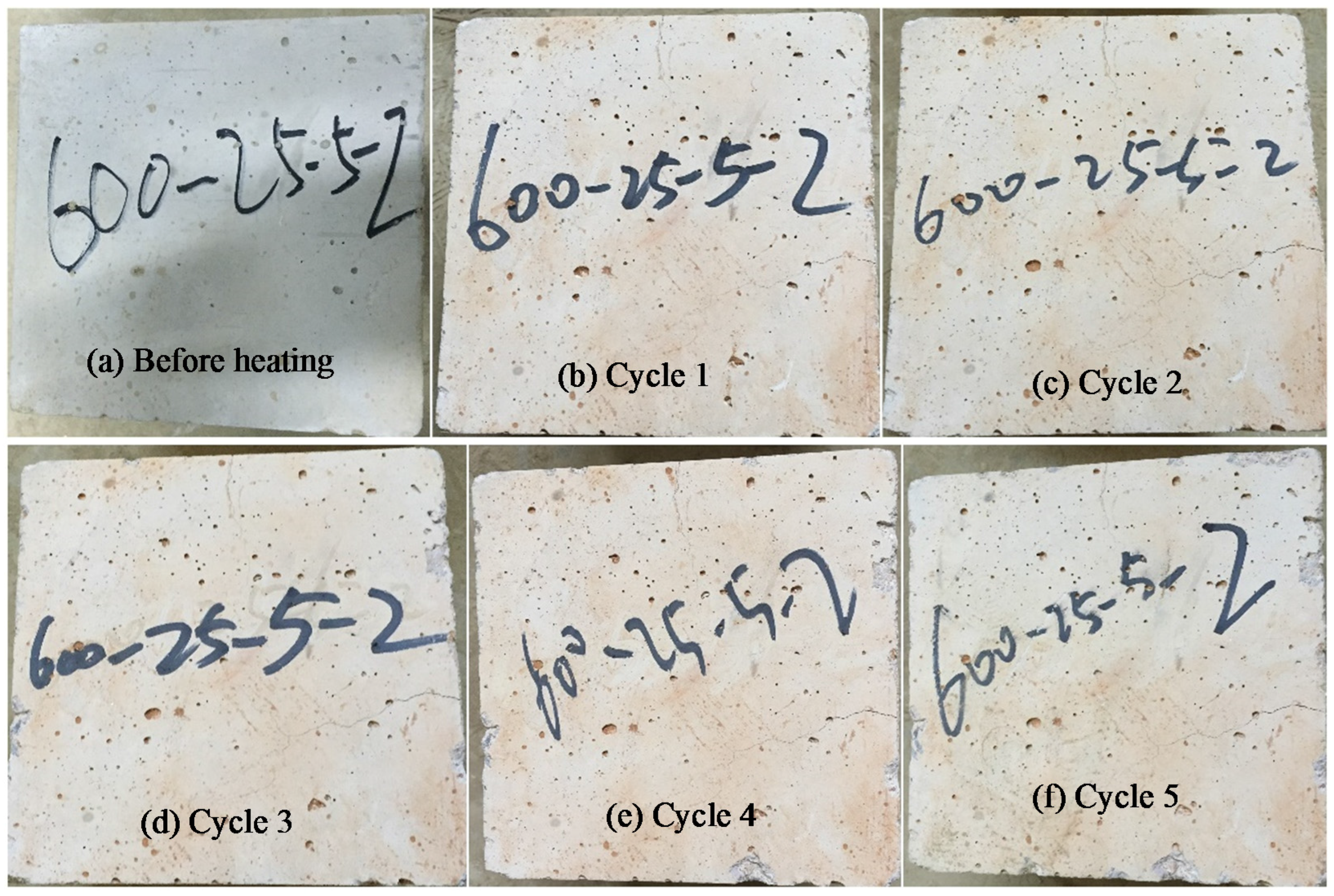
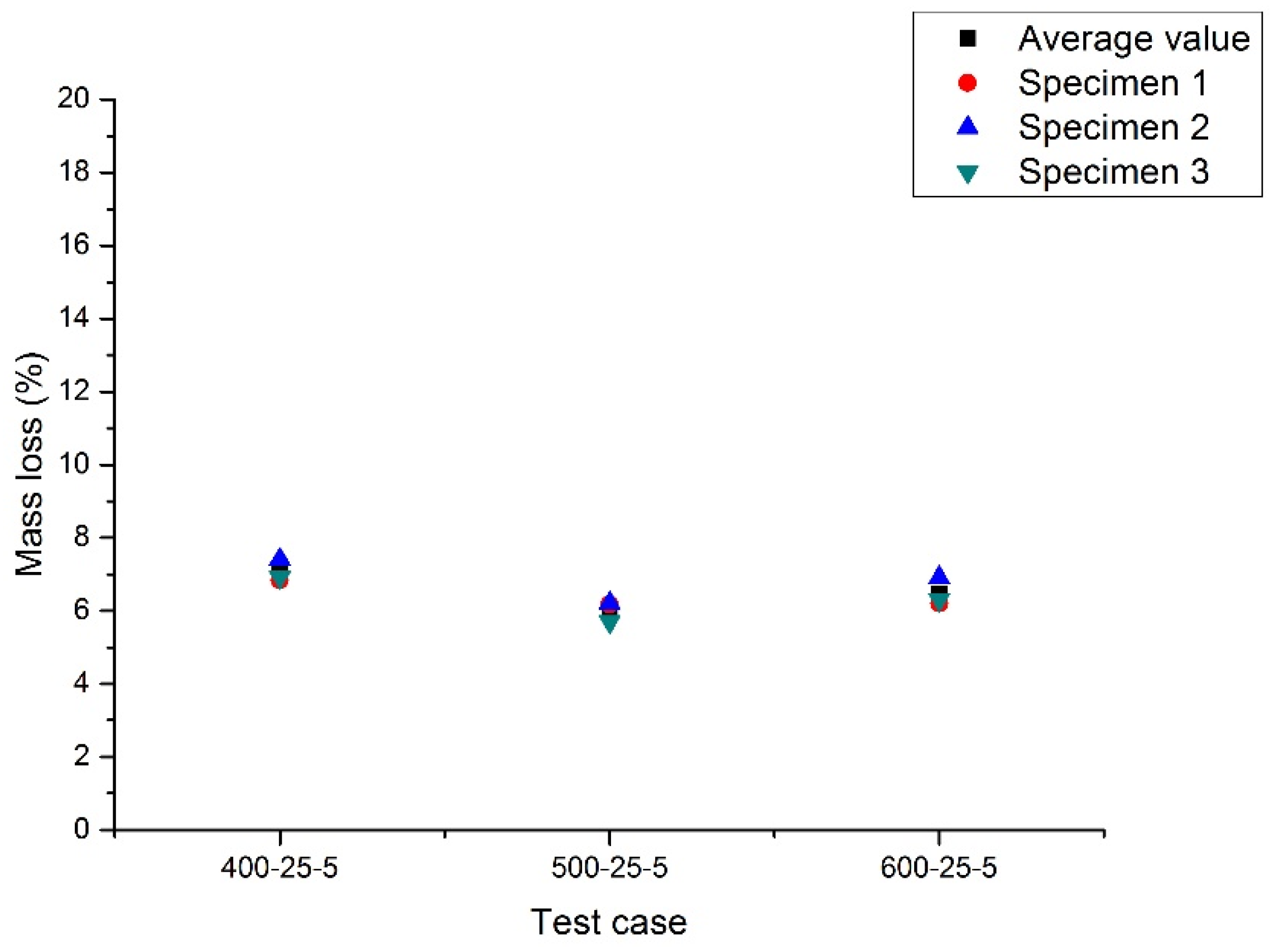
3.1.2. Thermal Cycling between Maximal Temperature and Ambient Temperature

Thermal cycling tests are performed on specimens between the maximal temperature (400, 500, and 600 °C) and ambient temperature (25 °C). Figure 9 illustrates color change of concrete during the thermal cycling in which the maximal temperature reaches 600 °C. The color of the concrete is gray white before heating, and it gradually turns gray red with thermal cycles. After thermal cycling, several micro-cracks appear on the surface and slight spalling occurs at the edges of the concrete specimens.
Figure 10 shows the mass loss of the three tests after thermal cycling. Three specimens in each test have similar mass loss. The mass loss of specimens in these tests is close and the average value is approximately 6.5%.

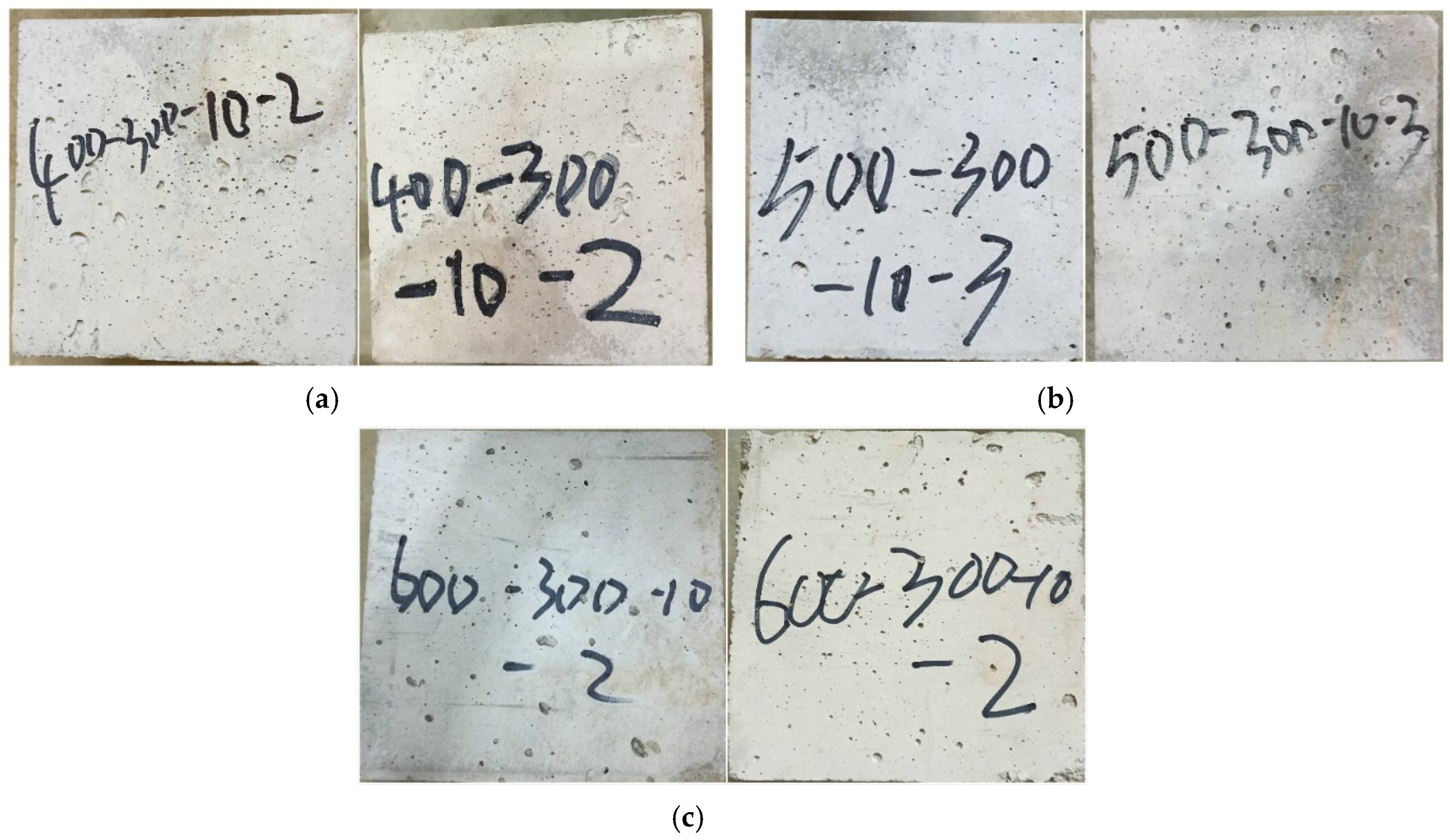
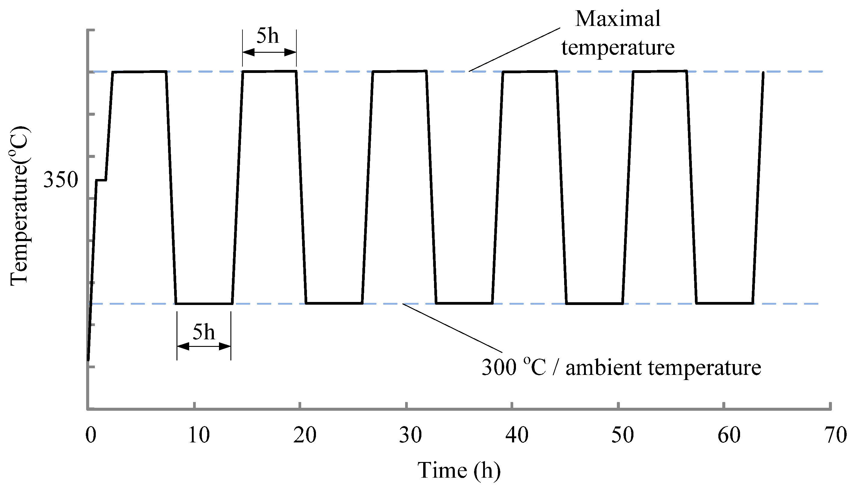
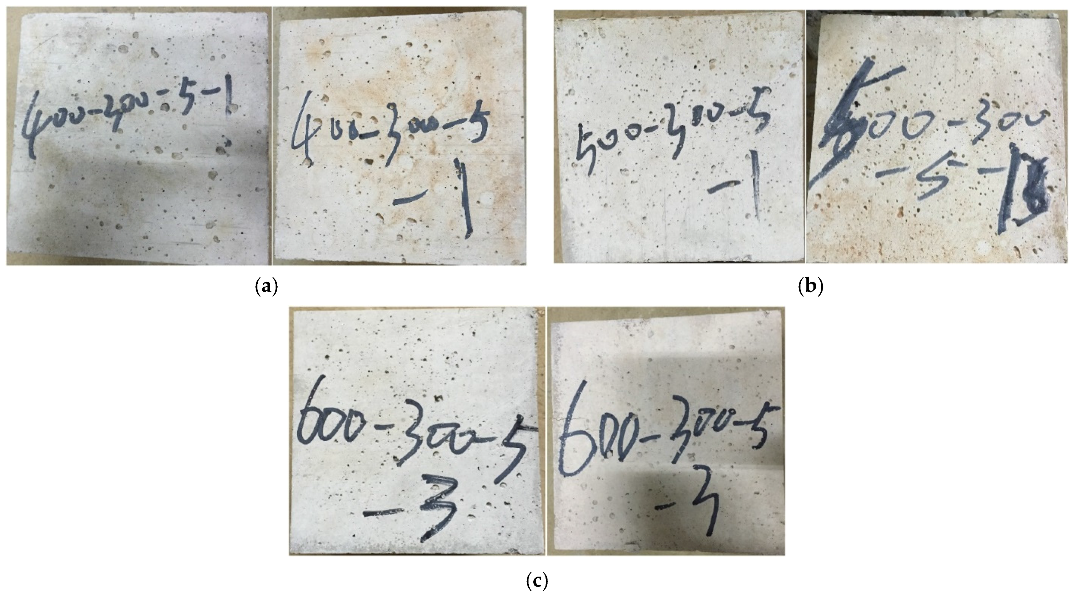
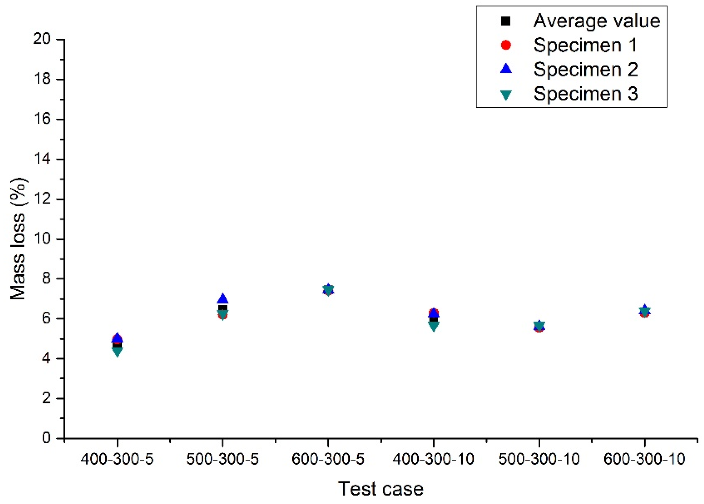
3.1.3. Thermal Cycling between Maximal Temperature and 300 °C

Thermal cycling tests are performed on specimens between the maximal temperature (400, 500, and 600 °C) and 300 °C. Two cases with different thermal cycles—i.e., 5-cycles and 10-cycles—are carried out. Figure 11 and Figure 12 show the comparison of concrete specimens before and after exposure to 5-cycles and 10-cycles, respectively. It is found that color change of concrete occurs after thermal cycles. Besides, micro-cracks are observed on the surface of the specimens. More micro-cracks appear in the concrete in the higher temperature tests. Compared with 5-cycles, 10-cycles may create more intensive micro-cracks in the specimens.
Figure 13 shows mass loss of the concrete specimens after thermal cycles. The mass loss is attributed to both leakage of water vapor and thermal decomposition accompanied by release of carbon dioxide. The water content in specimens may have minor differences, while the mass loss is close from different experiments. The average value of mass loss is about 6.0%, and is similar to the results in the non-cycling tests and the thermal cycling tests with a lower temperature of 25 °C.

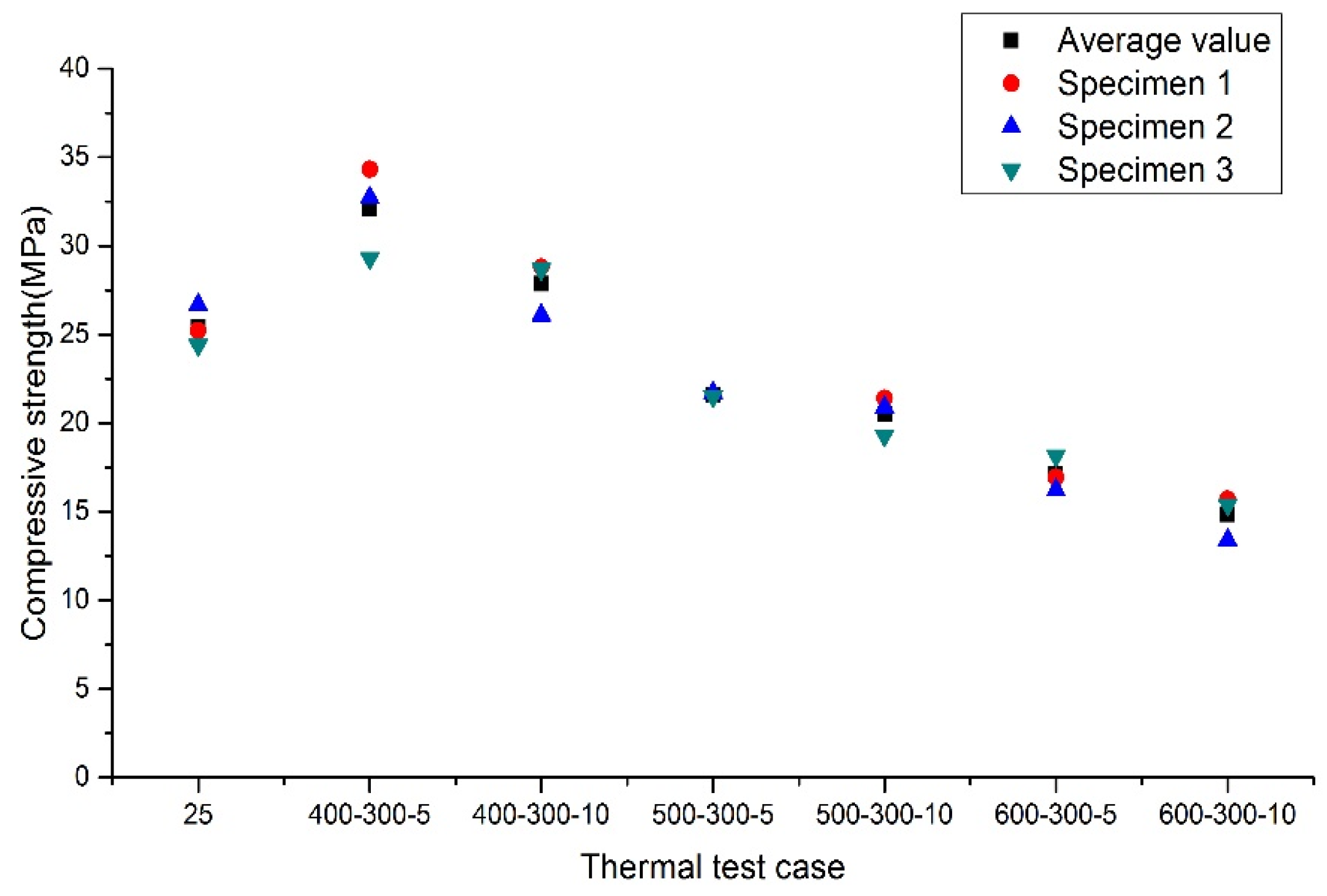
3.2. Uniaxial Compressive Tests

Compressive strength of the concrete specimens after exposure to high temperatures and cooling to room temperature is measured through a uniaxial compression test.
The compressive strength of concrete specimens subjected to high temperatures is shown in Figure 14 for non-cycling tests. The residual compressive strength of concrete and the loss ratio for different test cases is given in Table 3. The residual compressive strengths of the three specimens in each test case are close. The compressive strength of concrete slightly decreases from room temperature to 300 °C and is significantly reduced when the specimens heated up to 400 °C afterwards. The loss ratio in compressive strength of concrete subjected to 500 and 600 °C reaches 7.5% and 19.8%, respectively. The results show a similar trend with the previous studies [14].
Figure 15 and Figure 16 show the residual compressive strength of concrete exposed to thermal cycles. The residual compressive strengths of the three specimens are close in the same test case. The residual compressive strength is slightly decreased with the loss ratio of 3.6% in the test case 400-25-5, while significantly reduced in the test case 500-25-5 and 600-25-5. The loss ratio of these two cases is 27.4% and 39.8%, respectively. Regarding the thermal cycles with lower temperature of 300 °C, the loss ratio in compressive strength of concrete is less than 20% when the maximal temperature is under 500 °C, while it reaches 30%–40% when the maximal temperature up to 600 °C. Unusually, an increase of compressive strength of concrete is obtained in the test cases 400-300-5 and 400-300-10. There may be some chemical change in the concrete during heating at temperature ranging of 400–300 °C, and the mechanism of the increase needs further investigation.
According to the experimental results, thermal cycling causes more loss in compressive strength of concrete compared with the non-cycling cases, especially for high temperatures up to 500 °C afterwards. Besides, increased cycles may result in greater loss in compressive strength. After thermal cycles between 500 °C and 300 °C, 5-cycles cause loss ratio of 15.0% and 10-cycles cause 19.3%. While the loss ratio increases from 32.7% for 5 cycles to 41.7% for 10 cycles after specimens cycled between 600 °C and 300 °C.
The lower temperature, i.e., 25 °C or 300 °C, in the thermal cycling tests may influence the loss in compressive strength of concrete. After exposure to five thermal cycles between 500 °C and 300 °C, the loss ratio in compressive strength is 15.0%. In contrast, the loss ratio is greater and reaches 27.4% after thermal cycles between 500 °C and 25 °C. A similar trend is observed when the maximal temperature is elevated up to 600 °C, and the loss ratios are 39.8% and 32.7% for tests 600-25-5 and 600-300-5, respectively. It is recognized micro-cracks in the interface transition zones caused by different thermal responses between aggregates and cement matrices dominate the decline of compressive strength of concrete at high temperatures. During cooling the specimens, expanded aggregates appear to shrink, further propagating the micro-cracks in the interface transition zones. More intensive micro-cracks in concrete may be induced by cooling to 25 °C in the thermal cycling and thus there is more loss in compressive strength compared to that cooling to 300 °C.

4. Conclusions

In this study, mechanical stability of low-strength concrete (C20) as a thermal energy storage material is investigated using high thermal cycling experiments. In order to consider the operation condition of thermal energy storage, concrete specimens are thermally cycled at temperatures in the range of 400–300 °C, 500–300 °C, and 600–300 °C. For comparison, specimens also cycled at temperatures ranging of 400–25 °C (room temperature), 500–25 °C, and 600–25 °C. Non-cycling tests, in which specimens are exposed to 200, 300, 400, 500, and 600 °C, are also carried out. After thermal tests, residual compressive strength of the concrete is measured.
According to the tests results, concrete specimens in all the tests represent change of color and slight mass loss after exposure to high temperature. There is an approximate 5.0%–8.0% mass loss, which is attributed to both leakage of water vapor and thermal decomposition accompanied by release of carbon dioxide. Cracks are not observed on the surfaces of specimens until the temperature is elevated up to 500 °C. More micro-cracks appear in the concrete specimens after their exposure to thermal cycling, but the specimens remain stable without spalling.
There is mechanical deterioration of concrete when it is subjected to high temperatures. When the temperature does not exceed 400 °C, the compressive strength of concrete slightly decreases in the non-cycling tests and thermal cycling with lower temperature of 25 °C. Exposure of specimens to higher temperatures up to 500 and 600 °C result in a dramatic reduction of compressive strength of concrete. Thermal cycling leads to greater loss in compressive strength of concrete.
Although several micro-cracks appear in the low strength concrete and its compressive strength decreases 41.7% after 10 thermal cycles between 600 and 300 °C, the specimens remain stable without spalling. It is possible to use low strength concrete as a thermal energy storage material because of good mechanical properties and low cost. For engineering applications, behavior of concrete with embedded parallel tube heat exchangers is required further studies. Besides, long term performance of such concrete thermal storage systems under thermal cycling is also a matter of concern.

Acknowledgments

This work was supported by the Tsinghua University Initiative Scientific Research Program (No. 20151080439, and the National Natural Science Foundation of China (No. 51579133).

Author Contributions

Jianwen Pan conceived of this study. Jianwen Pan and Feng Jin designed the experiments; Chao Wu and Wen Zhong performed the experiments; Jianwen Pan and Chao Wu analyzed the data and wrote the paper.

Conflicts of Interest

The authors declare no conflict of interest.

References

  1. Gil, A.; Medrano, M.; Martorell, I.; Lázaro, A.; Dolado, P.; Zalba, B.; Cabeza, L.F. State of the art on high temperature thermal energy storage for power generation. Part 1—Concepts, materials and modellization. Renew. Sustain. Energy Rev. 2010, 14, 31–55. [Google Scholar] [CrossRef]
  2. Strasser, M.N.; Selvam, R.P. A cost and performance comparison of packed bed and structured thermocline thermal energy storage systems. Sol. Energy 2014, 108, 390–402. [Google Scholar] [CrossRef]
  3. Khare, S.; Dell’Amico, M.; Knight, C.; McGarry, S. Selection of materials for high temperature sensible energy storage. Sol. Energy Mater. Sol. C 2013, 115, 114–122. [Google Scholar] [CrossRef]
  4. Laing, D.; Steinmann, W.-D.; Tamme, R.; Richter, C. Solid media thermal storage for parabolic trough power plants. Sol. Energy 2006, 80, 1283–1289. [Google Scholar] [CrossRef]
  5. Laing, D.; Lehmann, D.; Fiß, M.; Bahl, C. Test results of concrete thermal energy storage for parabolic trough power plants. J. Sol. Energy Eng. 2009, 131, 041007. [Google Scholar] [CrossRef]
  6. Laing, D.; Bahl, C.; Bauer, T.; Fiss, M.; Breidenbach, N.; Hempel, M. High-temperature solid-media thermal energy storage for solar thermal power plants. Proc. IEEE 2012, 10, 516–524. [Google Scholar] [CrossRef]
  7. Laing, D.; Bauer, T.; Lehmann, D.; Bahl, C. Development of a thermal energy storage system for parabolic trough power plants with direct steam generation. J. Sol. Energy Eng. 2010, 132, 10111–10118. [Google Scholar] [CrossRef]
  8. Salomoni, V.A.; Majorana, C.E.; Giannuzzi, G.M.; Miliozzi, A.; Di Maggio, R.; Girardi, F.; Mele, D.; Lucentini, M. Thermal storage of sensible heat using concrete modules in solar power plants. Sol. Energy 2014, 103, 303–315. [Google Scholar] [CrossRef]
  9. Skinner, J.E.; Strasser, M.N.; Brown, B.M.; Panneer Selvam, R. Testing of high-performance concrete as a thermal energy storage medium at high temperatures. J. Sol. Energy Eng. 2013, 136, 021004. [Google Scholar] [CrossRef]
  10. Sakulich, A.R. Reinforced geopolymer composites for enhanced material greenness and durability. Sustain. Cities Soc. 2011, 1, 195–210. [Google Scholar] [CrossRef]
  11. Kong, D.L.Y.; Sanjayan, J.G.; Sagoe-Crentsil, K. Factors affecting the performance of metakaolin geopolymers exposed to elevated temperatures. J. Mater. Sci. 2007, 43, 824–831. [Google Scholar] [CrossRef]
  12. Shaikh, F.U.A.; Vimonsatit, V. Compressive strength of fly-ash-based geopolymer concrete at elevated temperatures. Fire Mater. 2015, 39, 174–188. [Google Scholar] [CrossRef]
  13. Ferone, C.; Colangelo, F.; Frattini, D.; Roviello, G.; Cioffi, R.; Maggio, R. Finite element method modeling of sensible heat thermal energy storage with innovative concretes and comparative analysis with literature benchmarks. Energies 2014, 7, 5291–5316. [Google Scholar] [CrossRef]
  14. Ma, Q.; Guo, R.; Zhao, Z.; Lin, Z.; He, K. Mechanical properties of concrete at high temperature—A review. Constr. Build. Mater. 2015, 93, 371–383. [Google Scholar] [CrossRef]
  15. John, E.; Hale, M.; Selvam, P. Concrete as a thermal energy storage medium for thermocline solar energy storage systems. Sol. Energy 2013, 96, 194–204. [Google Scholar] [CrossRef]
Figure 1. The appearance of the concrete specimens in the curing room.
Applsci 06 00271 g001
Figure 2. Temperature variation curves of the surface and internal of the specimens.
Applsci 06 00271 g002
Figure 3. Inverse analysis with different heat transfer coefficients (HTC).
Applsci 06 00271 g003
Figure 4. Reproduction of the internal temperature of the specimen 2 using the FE model.
Applsci 06 00271 g004
Figure 5. Heating scheme for thermal cycling tests.
Applsci 06 00271 g005
Figure 6. Uniaxial compressive strength test of the specimens after exposure to thermal cycling.
Applsci 06 00271 g006
Figure 7. Concrete specimens before (left) and after (right) exposure to high temperatures. (a) Exposure to 300 °C; (b) Exposure to 400 °C; (c) Exposure to 500 °C; (d) Exposure to 600 °C.
Applsci 06 00271 g007
Figure 8. Mass loss of the specimens after exposure to high temperatures.
Applsci 06 00271 g008
Figure 9. Concrete specimens exposed to thermal cycling (600-25-5). (a) Before heating; (b) After 1 cycle; (c) After 2 cycles; (d) After 3 cycles; (e) After 4 cycles; (f) After 5 cycles.
Applsci 06 00271 g009
Figure 10. Mass loss of the specimens after thermal cycling with lower temperature of 25 °C.
Applsci 06 00271 g010
Figure 11. Concrete specimens subjected to 5 thermal cycles before (left) and after (right). (a) Test 400-300-5; (b) Test 500-300-5; (c) Test 600-300-5.
Applsci 06 00271 g011
Figure 12. Concrete specimens subjected to 10 thermal cycles before (left) and after (right). (a) Test 400-300-10; (b) Test 500-300-10; (c) Test 600-300-10.
Applsci 06 00271 g012
Figure 13. Mass loss of the specimens after thermal cycling with lower temperature of 300 °C.
Applsci 06 00271 g013
Figure 14. Compressive strength of specimens after non-cycling heating.
Applsci 06 00271 g014
Figure 15. Compressive strength of specimens after thermal cycling with lower temperature of 25 °C.
Applsci 06 00271 g015
Figure 16. Compressive strength of specimens after thermal cycling with lower temperature of 300 °C.
Applsci 06 00271 g016
Table 1. Concrete mixture proportions.
Cement (kg/m3)Fly Ash (kg/m3)Fine Aggregates (kg/m3)Coarse Aggregates (kg/m3)Water (kg/m3)Additive (kg/m3)Entrained Air Content (%)
2101609968491702.162.1
Table 2. Test cases and heating scheme.
Test CasesMaximal Temperature (°C)Lower Temperature (°C)Thermal Cycles
400-300-5 14003005
500-300-55003005
600-300-56003005
400-300-1040030010
500-300-1050030010
600-300-1060030010
400-25-5400255
500-25-5500255
600-25-5600255
200 °C20025-
300 °C30025-
400 °C40025-
500 °C50025-
600 °C60025-
1 400 and 300 denote the maximal and lower temperatures, respectively, in the thermal cycling test. 5 is the cycle number.
Table 3. Loss ratio of compressive strength of the specimens after high temperatures.
Heating Test CasesCompressive Strength (MPa)Loss Ratio (%)
25 °C25.4-
200 °C24.3−4.3
300 °C25.2−1
400 °C24.2−4.8
500 °C23.5−7.5
600 °C20.4−19.8
400-25-524.5−3.6
500-25-518.5−27.4
600-25-515.3−39.8
400-300-532.126.2
500-300-521.6−15.0
600-300-517.1−32.7
400-300-1027.99.6
500-300-1021.4−19.3
600-300-1014.8−41.7

