1. Introduction
In recent years, the Internet of Things (IoT) has attracted much attention because of the provided functionalities that can advance humanity in terms of intelligence, automation, convenience, etc. The IoT can change objects that are precisely unidentifiable into identifiable, recognized, interconnected intelligent objects based on the standard communication protocols, called Smart Objects. The IoT consists of a number of smart objects that are embedded with wired/wireless communication interfaces to communicate and interact with each other without human intervention. The basic concept of IoT is that various smart objects can be automatically linked into a network for interacting with humans through perception and networking technologies. Smart objects in the IoT have the ability to send information through the Internet to provide the interaction among multiple things and people. For example, a smart power meter can get information with regard to energy usage from various electrical devices. Afterward, the smart power meter sends information wirelessly to the access point and the information is further forwarded to user devices through the Internet.
The development of IoT technologies can support a variety of applications, including the intelligent power grid [
1,
2,
3,
4], intelligent transportation [
5,
6], intelligent medicine and healthcare [
7,
8,
9,
10], intelligent art [
11,
12], intelligent logistics [
13,
14], intelligent environmental monitoring [
15,
16], smart life [
17,
18,
19,
20],
etc. In a smart home context, numerous smart objects need to use wireless communications due to the requirements of supporting mobile applications and maintaining neat living space. So far, numerous wireless technologies had been integrated and designed for various purposes, however, most applications of smart home neglect a well-designed wireless technology—ZigBee. ZigBee is an efficient short-range wireless technology in terms of power consumption and deployment scalability [
21]. It is a low-power wireless transmission protocol, providing a suitable data rate for control and monitoring purposes. ZigBee Alliance [
22] was formed in 1998 by Honeywell Corporation, whose main task is using IEEE 802.15.4 low-power wireless network protocols as the basis to develop the specification of IoT applications. However, most of the developed devices can only communicate with those devices that are also embedded with the ZigBee module.
A few recent papers [
23,
24,
25] aimed to develop an ambient intelligence system. However, most of them just proposed an architecture and pointed out some challenges in smart home. Different from the studies [
23,
24,
25], this paper pursues the goal of designing and implementing an IoT Access Point (AP) through which wireless devices such as projectors, laptops, and smart phones are allowed to access the local area networks or Internet. After designing the working system in an access point, we implement the IoT AP that not only is suitable for convenient deployment in a smart home but also covers both the gateway and AP. That is, the proposed IoT AP saves the hardware cost and energy consumption, as compared with two independent devices—a gateway and an AP. In the implementation, the IoT AP can be used for some smart spaces to automatically control the traditional TV, the air condition, the smart meter, the sphygmomanometer, the smart phone,
etc. The main contributions of this paper are itemized as follows.
1.1. More Challenges and Technique Depth
The functionality of Internet access via Wi-Fi has been commonly supported in APs. However, most commercial gateways cannot support Internet access for handheld devices. Instead, they mainly support data exchange between two devices via the Internets or Intranets, such as sensing information or command. Compared with the gateway, the AP has complex firmware and hardware. This leads to more challenge for embedding ZigBee protocol into an AP. The proposed IoT AP is developed based on a traditional AP and therefore inherits advantages of an AP as compared with the commercial gateways. For example, the implemented IoT AP not only support Internet access for mobile devices but also connect to IoT objects, which apply ZigBee as their communication interface. We should take the big challenge up for designing the IoT AP, which supports a various firmware and hardware. For example, the developed ZigBee protocol should be compatible with the existing AP firmware and hardware. We have embedded a ZigBee module and implemented the ZigBee and UPnP protocols such that the proposed IoT AP supports ZigBee communication capabilities over the Internet.
1.2. Convenience
Most of recent studies [
12,
24,
25] applied a gateway to receive the sensing data from IoT devices and forwarding data to the AP. However, the designed IoT AP combines the main functions of a gateway and an AP and, hence, allows a user to deploy a smart home with a convenient solution. It also decreases the deployment complex and reduces hardware costs.
1.3. Efficiency
Recent studies [
12,
24,
25] applied the gateway to collect data from sensors and subsequently forward the data to an AP using Wi-Fi wireless technology. However, using both of a gateway and an AP, the wireless resource must to be allocated to the additional data transmissions between them, reducing the throughputs and raising the contention problem. Applying the proposed IoT AP, the data collected from sensors are forwarded to the data server or data center via the Internet in a more efficient way because the gateway and AP has been integrated as an IoT AP.
1.4. Flexibility
Nowadays, a complete coverage in most capitals or cities has been achieved by widely deploying Wi-Fi APs. It is especially important to achieve the full coverage at home because it supports mobile devices with Internet access. The proposed IoT AP simultaneously supports ZigBee communications, Wi-Fi communications and Internet access capabilities by integrating the traditional Wi-Fi AP and the ZigBee protocol. Once an emergency event occurs, the ZigBee device can ask the IoT AP for competing the wireless resources with other Wi-Fi devices by the Wi-Fi interface such that the obtained wireless resources are allocated to ZigBee transmissions. This improves the unfair priority between ZigBee and Wi-Fi transmissions.
1.5. Avoidance of Interference between Wi-Fi and ZigBee
To avoid the interference of wireless signals, the Wi-Fi interface in the proposed IoT AP first detects the channels occupied by the other APs and subsequently notifies the ZigBee device management module the information of channels. Afterward, the ZigBee interface chooses the optimal channel for data transmissions, avoiding the starvation problem. This paper had integrated ZigBee and Wi-Fi protocols in the designed IoT AP to automatically avoid the signal interference between ZigBee and Wi-Fi by identifying and selecting an idle channel to sending command messages. Consequently, the proposed IoT AP properly schedules the ZigBee and Wi-Fi transmissions without any signal interference to establish the excellent communication environment in smart home applications.
1.6. Saving Cost and Energy Consumptions
Embedding ZigBee firmware and hardware to the existing AP can further reduce the hardware cost and energy consumption because the hardware and firmware components are highly integrated. In the performance study, the improvement of energy consumption is investigated.
The rest of this paper is described as follows.
Section 2 reviews the related works of the IoT AP.
Section 3 illustrates the system architecture of the designed IoT AP. The system implementation is presented in
Section 4.
Section 5 describes the implementation details of this paper. Finally,
Section 6 shows the simulation results of the implementation, whereas
Section 7 concludes this paper.
2. Related Works
The IoT supports various applications. Smart Life is one of the IoT supported applications that aims to make human beings’ lives more convenient. In literature, a large amount of papers had proposed the design and implementation of the IoT gateway. However, there are several differences between commercial IoT gateways and the developed IoT AP. The following presents the major differences.
In past literature, the communication technologies applied to home automation can be classified into three categories: the wired home automation system, the wireless home automation system, and the integrated home automation system.
For the
wired home automation system, Al-Aliand
et al. [
26] proposed a home automation system based on the Java language. This system implemented the home monitoring feature to electrical devices through the web service. Henceforth, this system needed to use the computer as a server, increasing the hardware and maintenance costs. Su
et al. [
27] proposed a remote system for controlling water temperature through transmission control protocol and Internet protocol (TCP/IP) protocol with lower hardware-cost. However, the remote controlling device needs to install a special software that poses inconvenience. Moreover, the operating procedure of multiple sensors at the same time is complicated. According to the complication, the
wired home automation system encounters some difficulties in wire provisioning, such as the deployment of communication lines between devices and the installation of back-end systems. These difficulties increase the build-cost so as to reduce the interest of users to afford a home automation system. Lucia
et al. [
28] and Shuaib
et al. [
29] designed a home gateway for ZigBee networks and Ethernet networks in the air pollutant monitoring and homecare applications. However, the designed ZigBee/Ethernet gateway did not support the functionalities of traditional AP. That is, the gateway can only exchange sensing data or commends between two devices via Internet or Intranet but cannot provide mobile device with Internet access. Compared with the existing gateway, the proposed IoT AP integrates the functionalities of a gateway and an AP, not only supporting the capability of Internet access for handheld devices but also reducing the hardware costs and energy consumptions. By applying the implemented IoT AP, users can intelligently/automatically/remotely control home objects by smart phones without additional payment for Internet access.
For the
wireless home automation system, Zhang
et al. [
30] designed a home gateway for ZigBee networks and universal mobile telecommunications system (UMTS) networks. Without supporting Wi-Fi access, all sensors embedded in the home appliances transmit their sensing data only via UMTS, but it is costly. Yang
et al. [
31] implemented an APP on a mobile phone that establishes the connection to the existing AP and supports the remote controls of Wi-Fi based home appliances. However, this communication highly depends on the Wi-Fi protocol and is hardly able to meet the basic communication requirements of IoT applications where a variety of appliances are embedded with various wireless communication protocols, such as ZigBee and Bluetooth, in the heterogeneous networks. Alheraish
et al. [
32] proposed a home automation system based on the global system for mobile communications (GSM). In this home automation system, each device was required to configure the GSM communication function and place in the location with high-quality GSM signals for connecting to other devices. Consequently, this system has not only the high cost, but also the straightlaced location restrictions. Study [
8] adopted a ZigBee router to achieve the local monitoring and the energy conservation for biomedical and healthcare applications. However, the monitored data are utilized only in a single home network and hardly developed smart e-home applications in a heterogeneous network.
The
integrated home automation system is the integration of personal wireless local area network (LAN) and Internet home automation system. In study [
33] proposed an integration system with various communication technologies, including Internet, GSM, wireless radio frequency (RF),
etc. In this system, the status of each device is monitored through wireless RF by a PC server, which links to the Internet, whereas users can also remotely control each device on/off by using the GSM protocol. However, the system architecture proposed in [
33] requires high equipment cost, resulting in the low interest of buyers. In study [
34] had proposed a home automation system based on wireless sensor networks. However, it requires a high-performance PC as a server and, hence, results in high equipment costs.
Gill
et al. [
25] proposed a smart life application based on a low-power ZigBee wireless sensor network. This study built three types of devices that have ZigBee communication capabilities, such as lightning control, heating machine, and environmental security system. To build a gateway with Wi-Fi and ZigBee communication capabilities, this system uses a notebook to remotely access and control ZigBee devices, e.g., turning the lamp switch on/off, setting the heater temperature, and setting a feedback threshold to the temperature sensors for indoor safety. Users applying the application [
25] are able to control ZigBee devices through the Internet, however, the ZigBee devices needs to be attached to a notebook or desktop computer for connecting to the Internet, increasing the construction cost.
In this paper, the considered home appliances are certified by ZigBee Alliance. In fact, we suggest that all home appliances should be ZigBee-certified to guarantee all the ZigBee devices successfully communicating with each other, even the ZigBee devices are made by distinct manufacturers. In addition, the proposed IoT AP simultaneously supports ZigBee, Wi-Fi, and Internet communications because it has been integrated the firmware/hardware in a traditional Wi-Fi AP and the ZigBee protocol. It is a feasible solution upgrading an original Wi-Fi AP to an IoT AP. This paper also uses the IoT AP to construct a smart home application. For instance, the power meter and power switch can be connected to the proposed IoT AP, measured for the detailed power consumption, and turned on/off. This reduces the cost and helps developers prevent hardware revisions.
3. System Architecture of the IoT AP
To build a smart life by applying IoT technologies, this paper proposes an IoT AP that is integrated with Ethernet, Wi-Fi, and ZigBee communication interfaces with related protocols. This section introduces the system architecture of the proposed IoT AP by
Section 3.1 that describes the functions of the IoT AP and
Section 3.2 that describes the detailed system architecture.
3.1. IoT AP Functionality
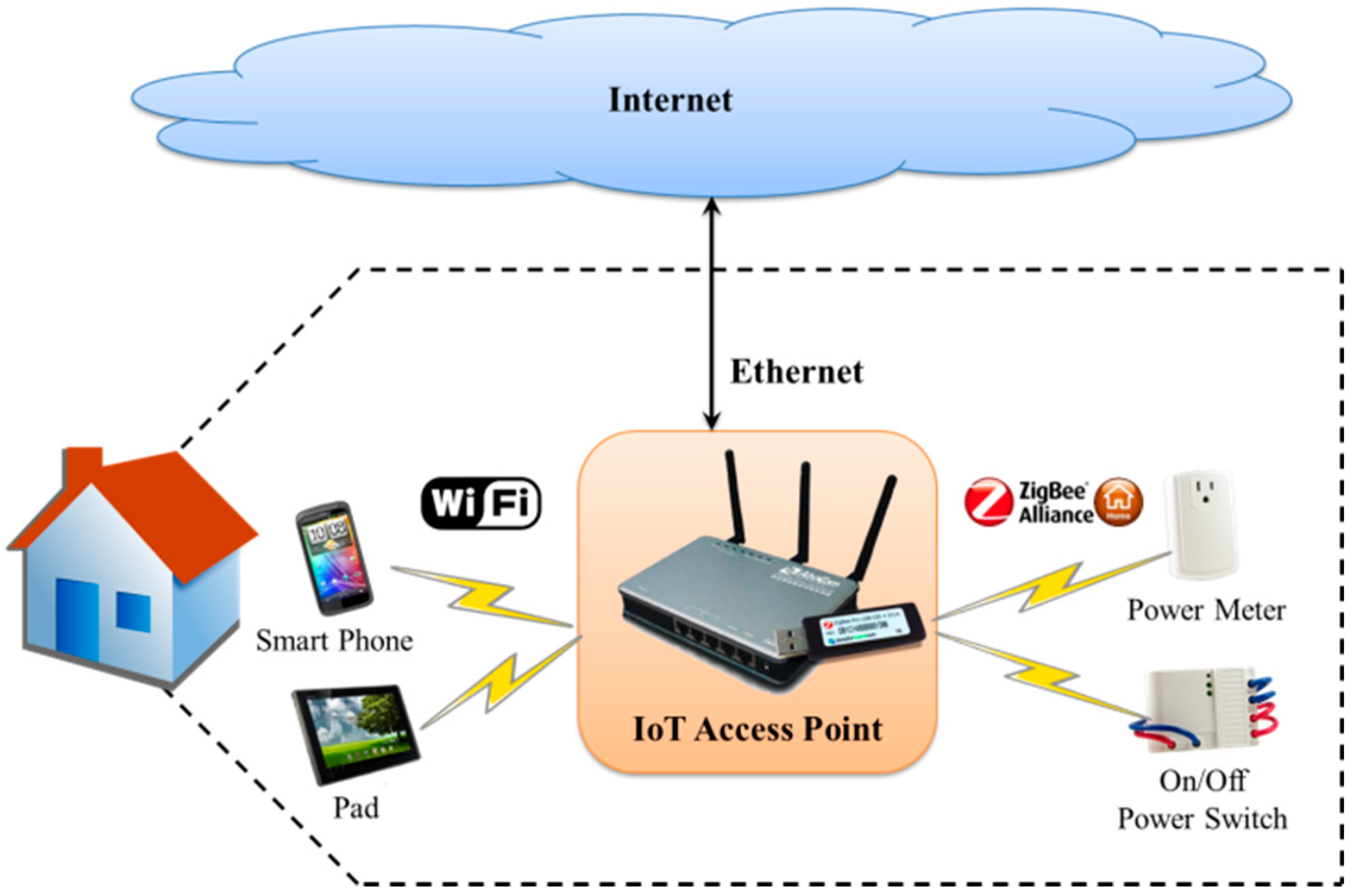
Figure 1 depicts the application scenario of the IoT AP for smart life where three network types are considered. The first one is Ethernet, which allows an AP connecting to Internet; the second one is Wi-Fi, which provides Internet connection for handheld devices via an AP; the third one is ZigBee, which is characterized by low-power and commonly embedded in sensors for environmental monitoring or event detection. However, it is unable to allow various network protocols to communicate with each other by using a traditional access point. Therefore, such heterogeneous network problem must be solved for building smart life.
Figure 1.
An Internet of Things (IoT) application: Smart Life scenario.
Figure 1.
An Internet of Things (IoT) application: Smart Life scenario.
To allow each device to communicate with each other within a heterogeneous network, this paper proposes an IoT AP that provides three main functions. First, it provides Internet connection and data conversion services between Wi-Fi and ZigBee networks. Then, it establishes a ZigBee network that allows home devices to communicate with each other by using the ZigBee wireless protocol. Finally, it provides a user interface control panel so that users can connect to IoT AP through the Internet to get the status of each ZigBee device at home and control them remotely.
ZigBee is a low-power wireless networking protocol with short-range transmissions. ZigBee Alliance develops this specification to allow developers carrying out their products, among which all of them are compatible. In addition, ZigBee provides several benefits once it is applied to IoT applications, including low power, low cost, low complexity, reliability, safety, and the support of a large number of network nodes. Based on the original Wi-Fi AP, this paper proposes the design and implementation of an IoT AP through the firmware update. The existing wireless AP is integrated with ZigBee wireless protocol to develop an IoT AP that provides ZigBee wireless communications, Wi-Fi wireless communications and Internet access capabilities.
To prevent illegal users manipulating the ZigBee devices at home, this paper further applies the universal plug and play (UPnP) technology, which constrains users to access the devices only through a LAN. To privately and remotely control home appliances, remote users can apply the virtual private network (VPN) technology to establish a private network connection for the IoT AP to access the ZigBee devices. Onno
et al. [
35] had proposed the VPN access for UPnP technology. Therefore, this paper does not further discuss VPN technology.
3.2. IoT AP System Architecture
The proposed IoT AP is integrated with the applied technologies in IoT smart home applications. As shown in
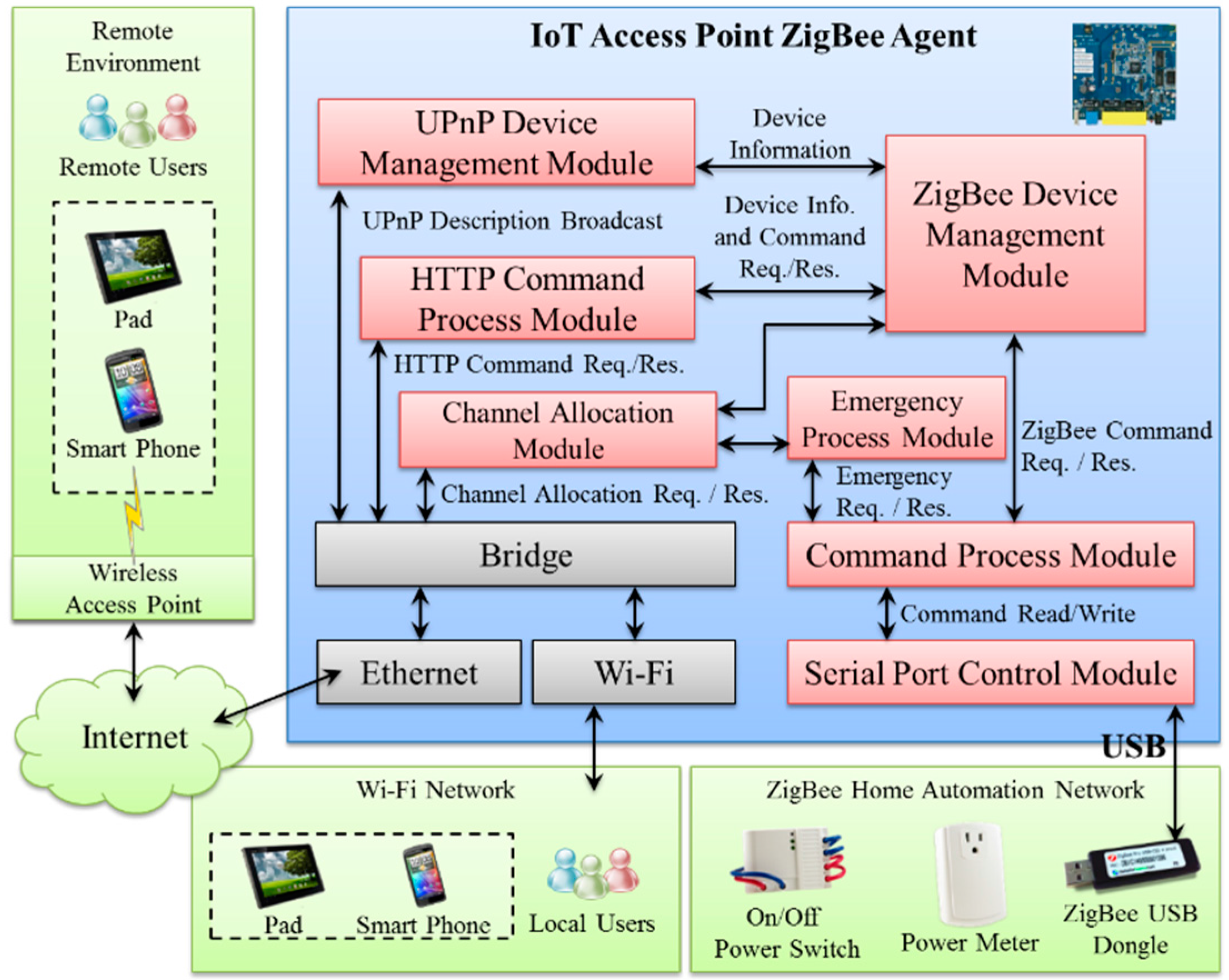
Figure 2, the IoT AP provides three types of communications within the heterogeneous network, such as ZigBee, Wi-Fi, and Ethernet. Through this IoT AP, a home network can be established to control home devices by using the low-power ZigBee protocol. Afterward, through the ZigBee agent embedded in the IoT AP, the remote and local users are able to obtain the access right of controlling the ZigBee-based home devices.
Figure 2.
The system architecture of the proposed IoT AP.
Figure 2.
The system architecture of the proposed IoT AP.
As shown in
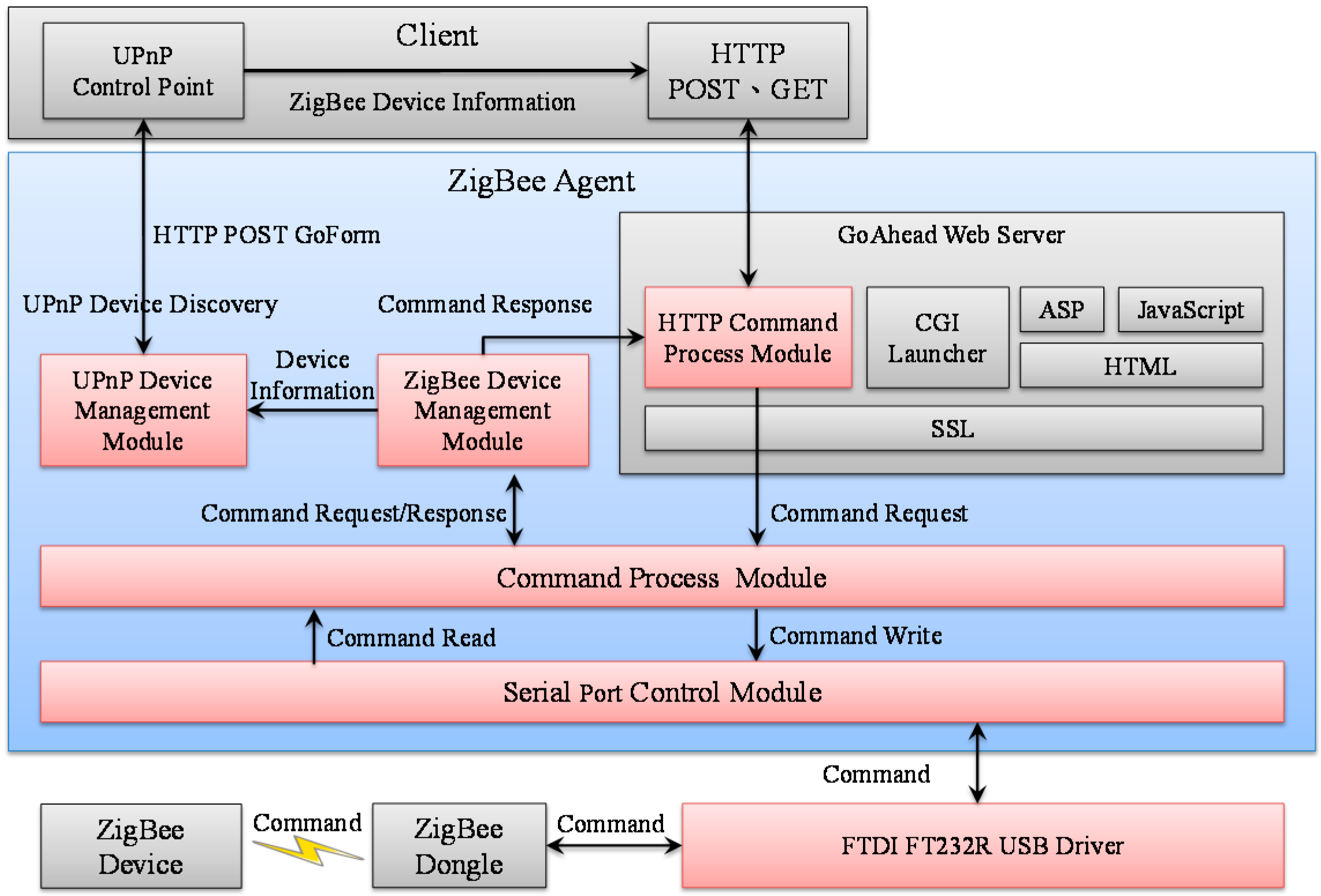
Figure 2, this paper presents the development of an IoT AP in which we had embedded the ZigBee agent into the existing Wi-Fi AP. Through the developed ZigBee agent, the remote users are able to control the ZigBee devices, which connect to the Internet. In the ZigBee agent, the
UPnP Device Management Module is installed in the IoT AP. This module allows the information of ZigBee devices to be broadcasted onto the network and hence these devices can connect with each other wirelessly. In addition, the remote handheld devices are able to discover the ZigBee devices by using UPnP protocol. The ZigBee agent mainly consists of five modules. Consider that a user wants to control some ZigBee devices, which are at home, by sending commands to the IoT AP via Ethernet or Wi-Fi. The
Serial Port Control Module provides reading and writing functions to ZigBee USB dongles. Upon the IoT AP receiving the command from a user, the
Command Process Module transfers it to the
Serial Port Control Module. The
Command Process Module uses the functions provided by
Serial Port Control Module to exchange and subsequently execute the command from ZigBee transceiver. After that,
Device Management Module sends the command to the
Command Process Module for grabbing the information of ZigBee devices and transferring it to the
UPnP Device Management Module and
HTTP Command Process Module. If the user command were sent by using HTTP, the
HTTP Command Process Module executes the command first and returns the results to grab the ZigBee devices information. As shown in
Figure 2, the
Channel Allocation Module implements the negotiation function of the channel usage between Wi-Fi and ZigBee networks. In addition, the
Emergency Process Module changes the ZigBee network from power saving mode to the emergency mode, increasing the opportunities of sensors to report their data readings.
4. System Implementation of IoT AP
The ZigBee agent plays the role of an intermediary device between a USB transceiver and a ZigBee device. The ZigBee agent connecting to the ZigBee device provides the ZigBee control service for users through the Internet. In this paper, we develop the ZigBee agent based on the embedded Linux by installing RT3052 development board.
Figure 3 depicts the system architecture of the developed ZigBee agent consisting of ZigBee modules, including the
Serial Port Control Module, the
Command Process Module, the
ZigBee Device Management Module, the
UPnP Device Management Module, the
HTTP Command Process Module, the
Channel Allocation Module, and
Emergency Process Module. The details of module functionalities are elaborated in the next paragraph.
Figure 3.
The ZigBee Agent system architecture.
Figure 3.
The ZigBee Agent system architecture.
4.1. Serial Port Control Module
The main task of this module is to establish the USB serial port in the Linux operation system (OS). This module provides read and write functionalities for the Command Process Module. In this paper, the ZigBee transceiver communicates with other devices through a ZigBee USB dongle that is connected to the IoT AP. The communication chip used in the USB is FTDI FT232R. The source code of Linux-2.6.21 contains FTDI drivers that can be configured by a user in the Linux kernel. If a USB transceiver was connected to the IoT AP, a file named “ttyUSB0” appearing in the /dev root folder indicates that the USB is detected.
In the implementation, this paper uses the open-source library [
36], which is available on the Internet to control the serial port. This open-source library is used to enable the 8N1 (eight data bits, no parity, one stop bit) for the serial port. It also supports data reading and writing functions for the serial port, which is applicable in Windows and Linux OS. Through this open-source library, the ttyUSB0 allows the
Serial Port Control Module and the ZigBee transceiver to communicate with each other. Therefore, the serial port is able to support command sending and receiving functions for the
Command Process Module and the
HTTP Command Process Module.
4.2. Command Process Module
A ZigBee transceiver sends a streaming command with several requirements to a ZigBee agent. Upon receiving the command from the ZigBee module, the
Command Process Module sends it to the corresponding module for execution. The ZigBee transceiver belongs to the
Simple Home Net Company that supports a variety of commands to control the ZigBee devices. The details of numerous commands are presented in the user manual [
37].
4.3. ZigBee Device Management Module
To allow ZigBee agent to manage several ZigBee devices simultaneously, ZigBee Device Management Module handles user commands that are sent from the Command Process Module. According to the user command, this module collects the information with regards to the required ZigBee devices and translates each of them into a specific streaming format with several fields, i.e., a management information. After that, the ZigBee Device Management Module provides the management information to the UPnP Device Management Module and the HTTP Command Process Module.
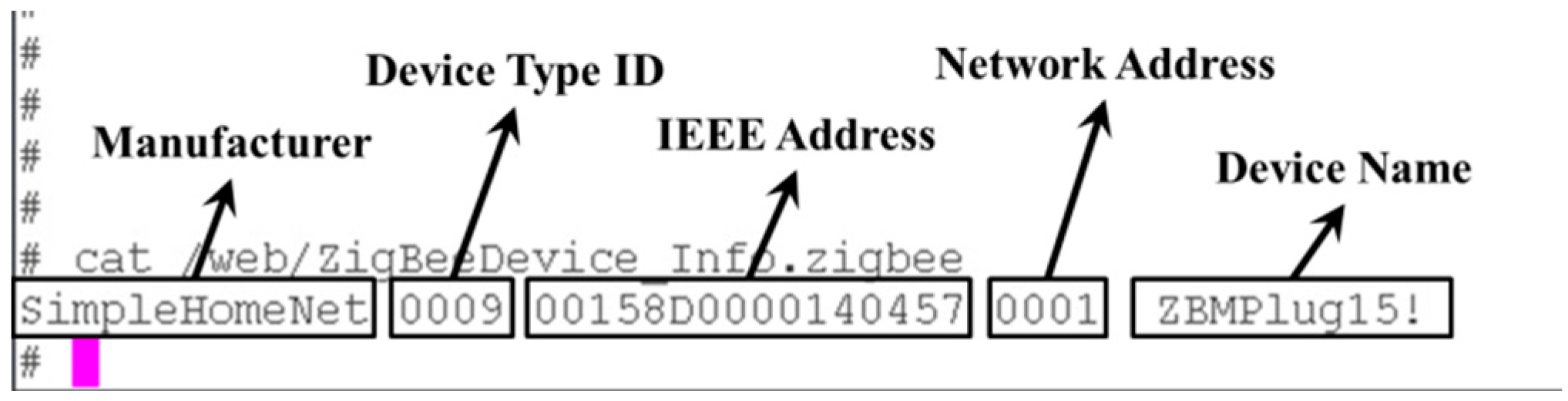
To implement the aforementioned feature, this module needs to complete three tasks. First, to efficiently manage each ZigBee device, this module needs to stipulate a data structure to save the management information for each ZigBee device. As shown in
Figure 4, the recorded information contains the device identifier, the IEEE address, the network address, the device name, the returned commands,
etc. The IEEE address is the unique number for each ZigBee device in the world. In this paper, it stands for the identification number of a ZigBee device. When this module receives a new IEEE address, it means that a new ZigBee device joins to this local network. In this situation, this module collects the information of the new ZigBee device. Second, this module frequently accesses the existing ZigBee device for maintenance. If this module discovers that a ZigBee device does not exist anymore, the ZigBee device will be removed from the maintenance list. Third, when the
Command Process Module returns a result for the command, such as the result “on” or “off” for the command of reading the status of a ZigBee device, this result is recorded or updated in the device information. Finally, the record is sent to the
HTTP Command Process Module.
Figure 4.
Management Information of ZigBee Device. The pink mark is the command input mark in the CLI (command line interface) mode of Linux.
Figure 4.
Management Information of ZigBee Device. The pink mark is the command input mark in the CLI (command line interface) mode of Linux.
4.4. UPnP Device Management Module
To allow remote users to discover the ZigBee devices, the UPnP Device Management Module applies the UPnP protocol to broadcast the information of ZigBee devices on to the network. Therefore, the remote users are able to discover the ZigBee devices and subsequently perform the control accesses of the ZigBee devices.
UPnP is a service discovery protocol proposed by the UPnP Forum. The main purpose of this protocol is to allow various devices connected with each other in a home network. To achieve this goal, the UPnP forum developed an UPnP device control protocol based on the Internet communication network protocol standard. UPnP protocol consists of three basic components, including the device, the service, and the control point (CP).
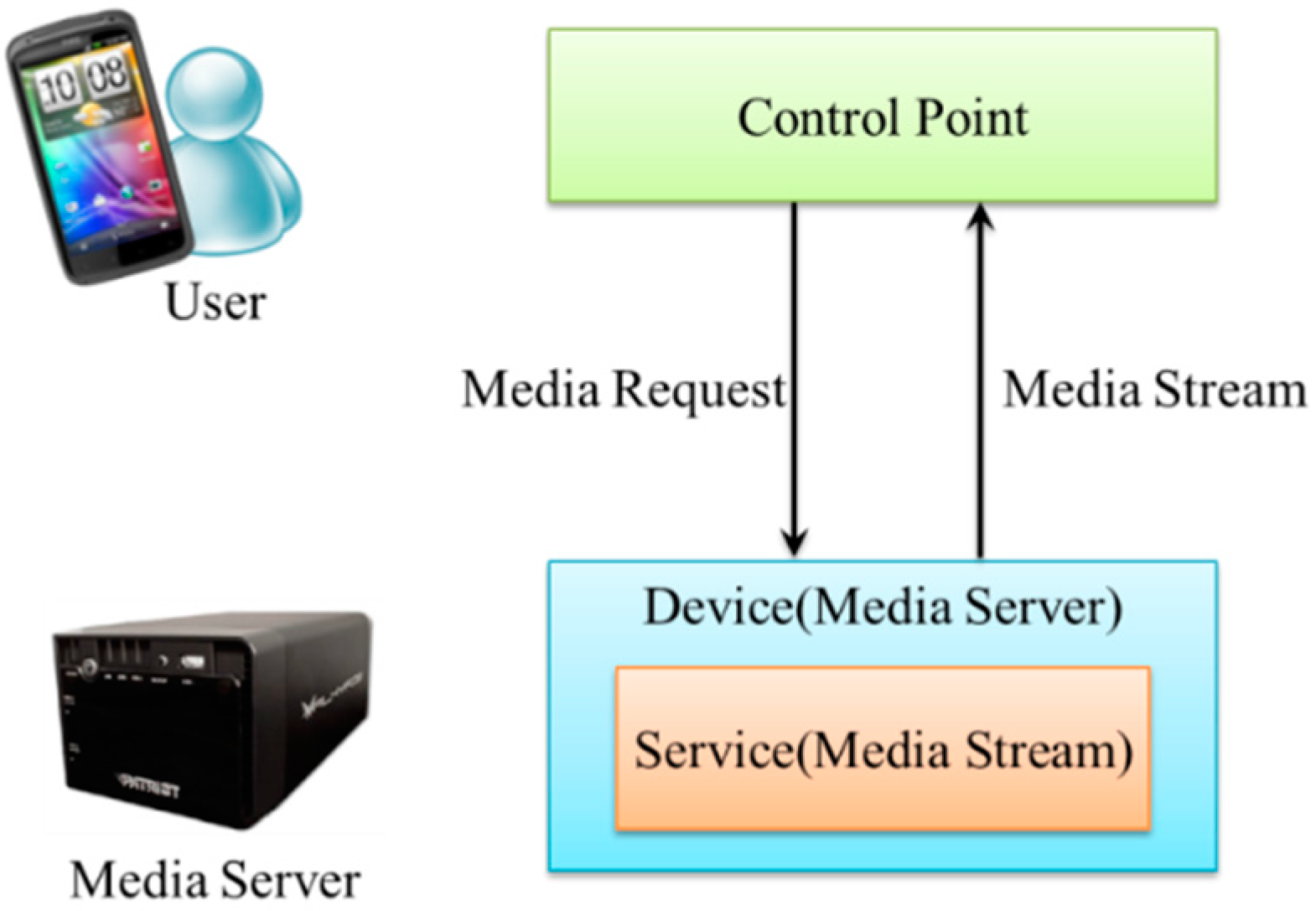
Figure 5 depicts that a user controls UPnP devices through a smartphone. Initially, the UPnP software application is installed in the smartphone, namely the UPnP CP. It is responsible for searching and controlling the UPnP devices. In this situation, the UPnP device plays the role of a media server that provides streaming to execute the command for processing the CP. After a smartphone has discovered a multimedia server, it requests a media streaming. The realization of UPnP streaming is divided into five main steps, including
Discovery,
Description,
Control,
Event Notification, and
Presentation. In the
Discovery step, the smartphone allows the control point to broadcast its service through SSDP protocol. After the control point has joined the network, the cellphone can search for the UPnP devices in the network. In the
Description step, UPnP device uses XML method to provide information (nickname, serial number, manufacturer name, brand,
etc.), service list, control, event and other relevant information for the manufacturer. In the
Control step, a CP sends a control message to UPnP device and subsequently the device can be controlled according to the control message. In the
Event Notification step, control point can subscribe a service. When the device status changes, the service sends the message to control point in XML format. In the
Presentation step, UPnP device can allow the control point to obtain the device status or control through a webpage. Based on the protocols mentioned above, the UPnP Forum standardizes various devices such as printers, multimedia servers,
etc., with a variety of functions. However, the standardized devices are unable to cover all the ZigBee devices. Therefore, in this paper, the IoT AP uses UPnP protocol to broadcast the ZigBee devices. The following describes how IoT AP uses UPnP protocol to obtain the ZigBee devices status.
Figure 5.
UPnP basic components diagram.
Figure 5.
UPnP basic components diagram.
To discover the UPnP devices, this paper implemented
UPnP Device Management Module by using open-source portable UPnP library [
38]. This module operates by obtaining information of the ZigBee device from the ZigBee Device Management Module. Afterward, it puts the information of ZigBee device into UPnP device description file, and subsequently the ZigBee device broadcasts the information of local devices. Therefore, the remote user enable to discover this UPnP device by description file. As shown in
Figure 6, this file contains IEEE address, network address, device ID, ZigBee device information and GoAhead web server port and URL. Therefore, when the ZigBee device is removed, this module also removes the corresponding UPnP device. By using the method described above, this module has the ability to manage UPnP devices and allow remote users to search the ZigBee devices through UPnP protocol.
Figure 6.
UPnP device descriptions.
Figure 6.
UPnP device descriptions.
4.5. HTTP Command Process Module
The IoT AP sends and receives commands to/from remote user through HTTP standard protocol. Therefore, a web server is required on the ZigBee agent side. Among the large number of web servers, GoAhead web server is the one that is commonly used in embedded systems. This web server is built on top of the device management framework so that it is unnecessary for users to use additional programs to develop the applications which also support SOAP and XML-RPC protocols. The main function of this web server is supporting ASP and JavaScript by using the general CGI execution and the standard built-in CGI to perform GoFrom and subsequently save the web page files to the ROM or the file system. In addition, GoAhead web server is open-source that can run on several types of platforms. Therefore, the user can freely modify or spread the source code in terms of the GPL standard.
4.6. Channel Allocation Module
As shown in
Figure 2, to avoid channel interference, a
Channel Allocation Module is designed for channel negotiation and allocation between Wi-Fi and ZigBee networks after receiving the available channels list from Wi-Fi interface. The Wi-Fi interface has a quick response time for channel scanning and report to the Channel Allocation Module. A channel that does not overlapped with the existing channels used in Wi-Fi or ZigBee is allocated to the ZigBee coordinator such that the newly formed ZigBee network can avoid contention and collision.
4.7. Emergency Process Module
As shown in
Figure 2,
Emergency Process Module allows ZigBee networks to switch mode from power saving to emergency. Staying in the emergency model, the ZigBee network utilities a short frame that allows each device reporting their readings to the coordinator with more opportunities. Consequently, the emergency control can be achieved as soon as possible.
5. Building Smart Home by Using IoT AP
To provide access and control services for remote users, the ZigBee devices are connected to the network layer of the IoT AP. Therefore, the remote user can use a smart phone or tablet as the remote control device to control the ZigBee devices.
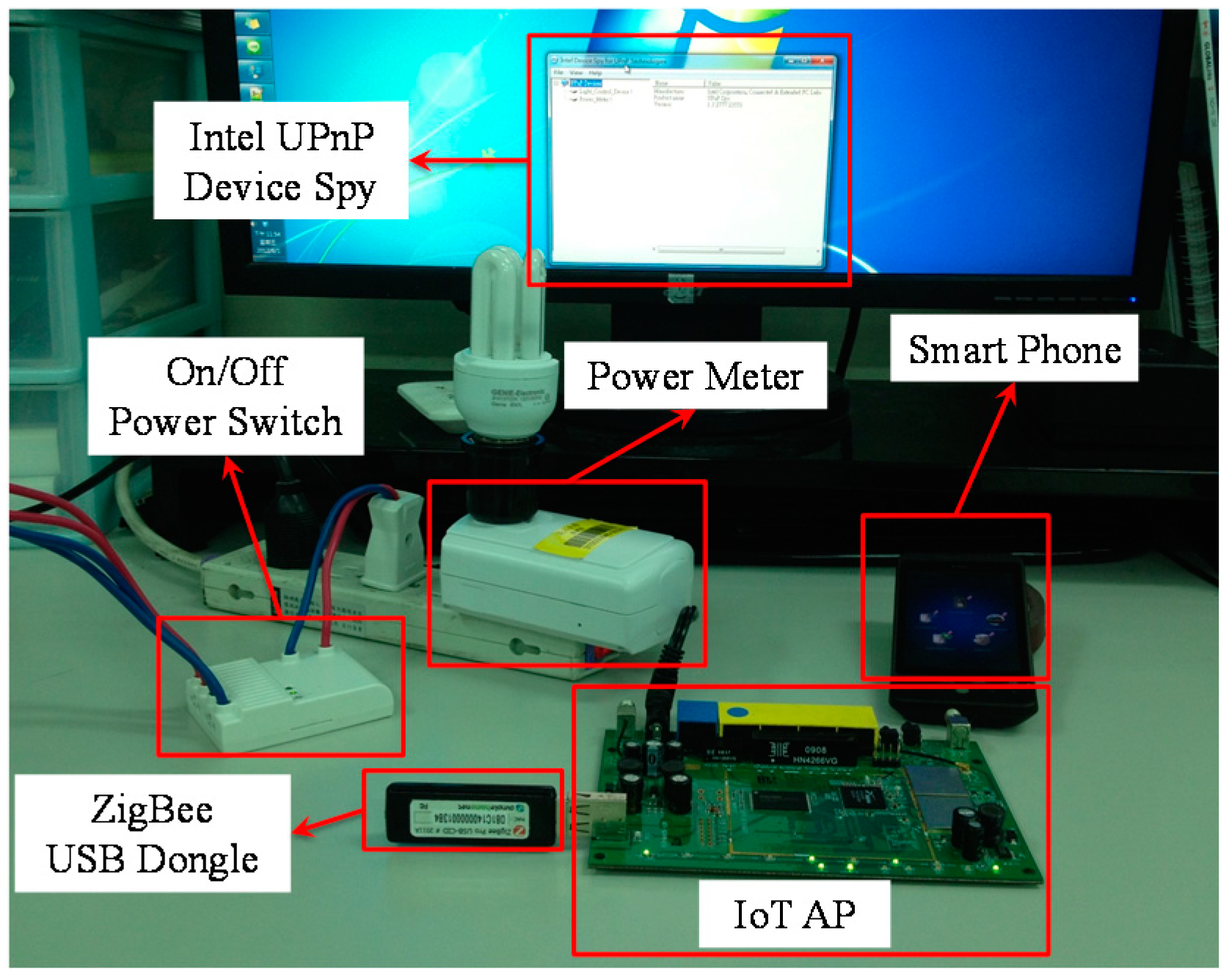
As shown in
Figure 7, this section explains the development of the proposed IoT AP to build a smart home application. This paper proposes the configuration of two ZigBee devices, which are the power meter and on/off power switch. These devices are sold by simple home net company and have been certified by the ZigBee Alliance. In
Section 5.1 the description of ZigBee devices configuration for home automation system is presented.
Section 5.2 describes the configuration of the wireless Internet protocols channel for ZigBee and Wi-Fi.
Section 5.3 describes the utilization of UPnP and HTTP to verify the correctness of the ZigBee agent operation.
Figure 7.
Smart Home system established by the IoT AP.
Figure 7.
Smart Home system established by the IoT AP.
5.1. ZigBee Home Automation Device Configuration
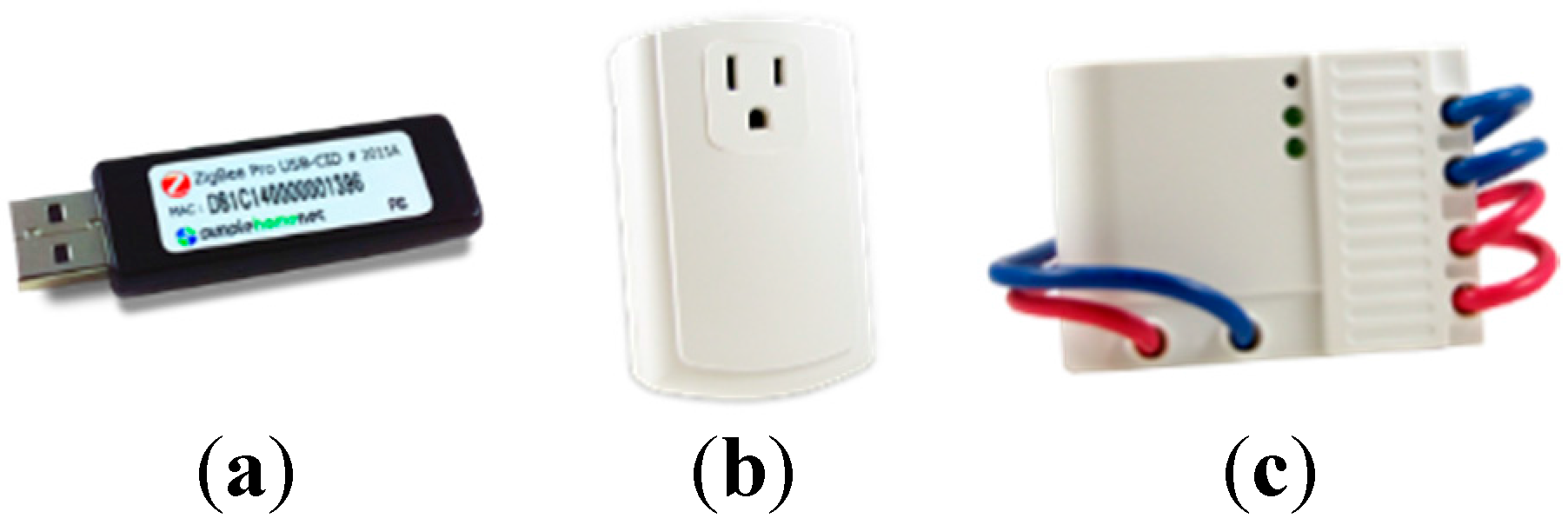
This paper uses the ZigBee devices that have been certified by ZigBee Alliance to build ZigBee Home Automation Network. As shown in
Figure 8, the IoT AP is connected to the ZigBee transceiver, Power Meter and On/Off Power Switch.
Figure 8.
ZigBee devices. (a) Transceiver; (b) Power Meter; and (c) On/Off Power Switch.
Figure 8.
ZigBee devices. (a) Transceiver; (b) Power Meter; and (c) On/Off Power Switch.
5.1.1. ZigBee Transceiver
ZigBee transceiver has a USB port that allows a connection to the computer or the embedded device. The chip used for the USB interface is the FTDI FT232RC and the FTDI VCP driver is installed on the computer/embedded device for operation. According to the user manual provided by Simple Home Net Company, the commands for controlling the ZigBee transceiver can be sent or received through the USB port.
5.1.2. Power Meter
The power meter is mainly used for measuring the power consumption and controlling the power switch. It has a three-pin plug with 110 V fixed power supply to provide power supplement for electronic devices. The power meter can limit the power usage of electronic devices by using the circuit restriction capability.
The power meter plays the role of a router with the capabilities of extending the ZigBee network and receiving a number of commands. In this paper, six types of commands are used for this device. There commands are: reading the IEEE Address, reading the device ID, reading device name, obtaining the On/Off status of a device and controlling the power switch.
The power meter has a button and a LED light to display the device status. In implementation, the surrounding ZigBee devices, which plays the role of a coordinator or router to allow other devices to join the network. After the power meter powers up, it automatically joins the network and switch to the state that allows other devices to join the network. In this situation, the LED light blinks once per second. To reset the power meter, simply just unplug the power source to cut its power and hold the button. While holding the button, plug the power meter back to the socket and wait for two seconds. Afterward, release the button and the power meter has been restored to its factory settings.
5.1.3. On/Off Power Switch
This device is mainly used for controlling the power switch. For example, lamp switch can be controlled on/off and the on/off power switch is hidden behind a decoration. The on/off power switch have two sets of power switch. On the interface, it has a wire that is used connect to a standard power cable at home. The wire is also used to connect to the electronic device that is desired to be controlled. The on/off power switch uses fixed power. Therefore, it has the same function as the power meter in ZigBee networks.
5.2. ZigBee/Wi-Fi Wireless Channel Configuration
The proposed IoT AP performs two wireless protocols at the same time, including ZigBee (IEEE 802.15.4) and Wi-Fi (IEEE 802.11n). The ZigBee home network environment can be established by a ZigBee wireless protocol. The ZigBee devices are connected with each other within the established smart home environment. On the other hand, the Wi-Fi wireless protocol can provide access to the ZigBee devices for handheld devices through the Internet. However, ZigBee shares a 2.4 GHz industrial, scientific, and medical (ISM) band with other existing radio transceivers such as Wi-Fi. Therefore, coexistence of ZigBee with Wi-Fi becomes an increasingly important issue because of their wideband and popular uses.
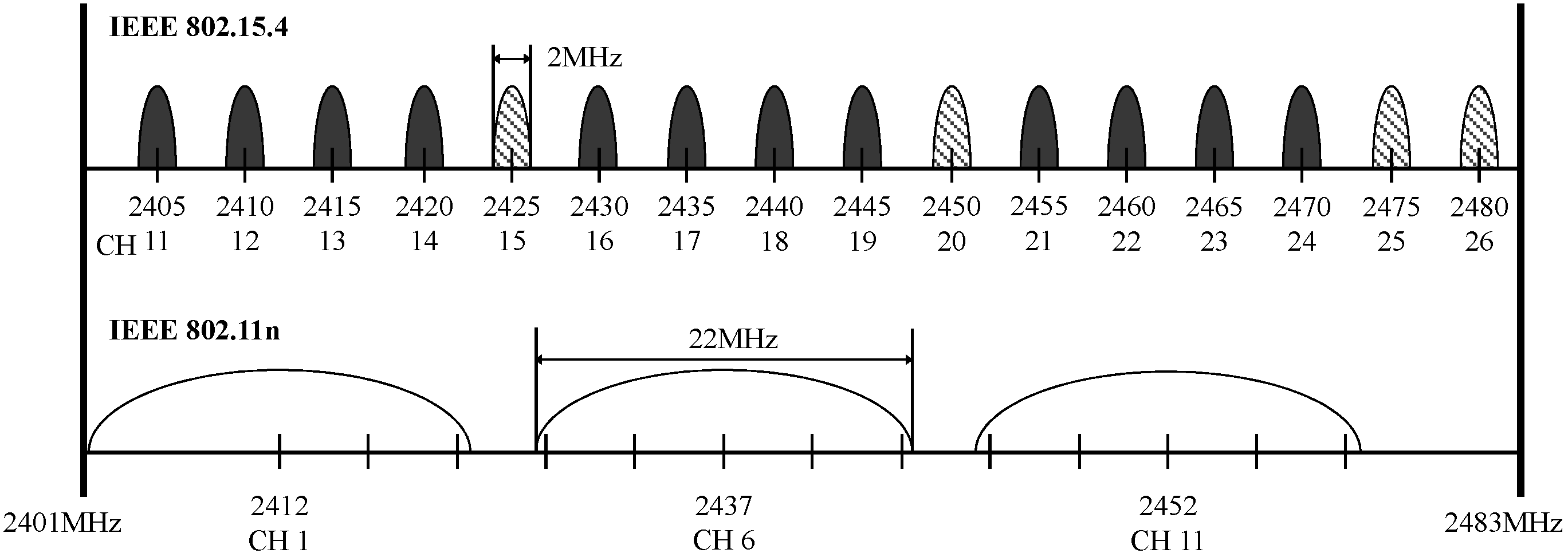
The ZigBee communication protocol divides each 5 MHz frequency band into 16 channels with channel numbers 11–26. The frequency of each channel is 2 MHz and there is no spectral overlap between channels. The Wi-Fi communication protocol divides the frequency band into 13 channels with channel numbers 1–13. The coverage area of each channel is 22 MHz. Therefore, the spectral overlaps do not overlapped among channel 1, channel 6, and channel 11. Because the spectral overlap causes reduction of transmission speed, channels 1, 6, or 11 are used for channel configuration of Wi-Fi network in the established environment. As shown in
Figure 9, ZigBee shares the congested 2.4 GHz ISM band with an IEEE 802.11n WLAN with wide RF bandwidth. To reduce the opportunity of the interference of wireless signals, this paper makes Wi-Fi with higher opportunity to occupy one of the three channels 1, 6, and 11, whereas ZigBee higher opportunity to occupy one of the four channels 15, 20, 25, and 26, which fall between the non-overlapping IEEE 802.11n channels. Consequently, the proposed IoT AP can normally operate ZigBee and Wi-Fi without any signal interference and the smart life application can be built by using the proposed IoT AP.
Figure 9.
Spectrum comparison between IEEE 802.15.4 and 802.11n.
Figure 9.
Spectrum comparison between IEEE 802.15.4 and 802.11n.
5.3. Access Verification Method for Remote Users
In this section, this paper presents a verification of the proposed method to guarantee that the IoT AP operates normally and verify two parts, including the UPnP device scanning and HTTP command exchange.
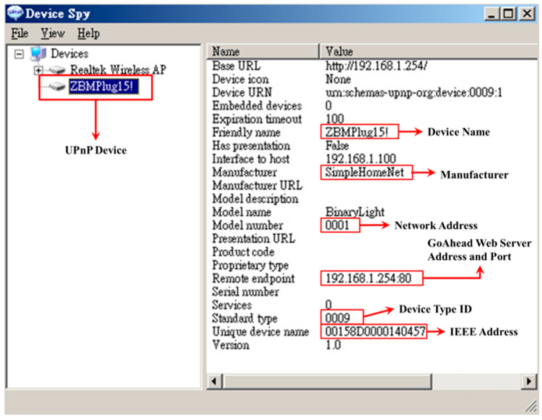
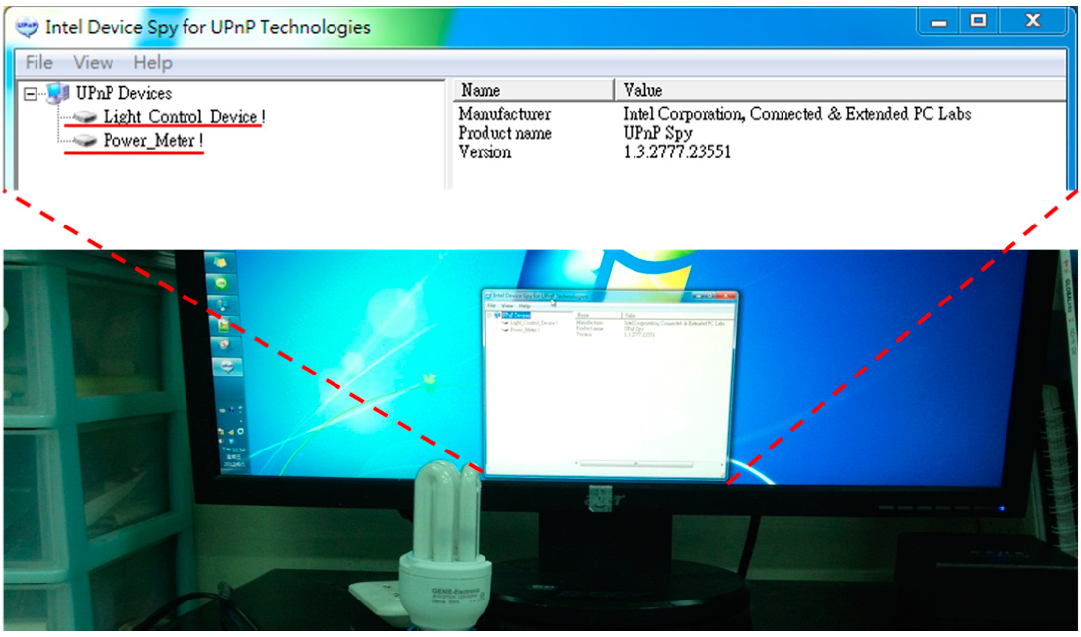
In the UPnP verification, this paper uses a tool created by Intel Company and developed by UPnP developers, namely Intel
® Software for UPnP Technology. This tool contains Device Spy which can reveal the existing UPnP devices, as well as Device Sniffer which can monitor the UPnP packet delivery. In addition, there are multimedia Controller, Renderer, and Server which can allow the UPnP multimedia applications to be operated directly on a Windows computer. This paper uses the desktop computer, notebook computer, and smart mobile phone connecting to the designed IoT AP through Wi-Fi and uses Device Spy to confirm whether or not the IoT AP broadcasts the ZigBee devices through the UPnP. As shown in
Figure 10, two UPnP devices can be found by using the Device Spy. The device information can be obtained by clicking one of the devices.
Figure 10.
Using Device Spy to find UPnP devices.
Figure 10.
Using Device Spy to find UPnP devices.
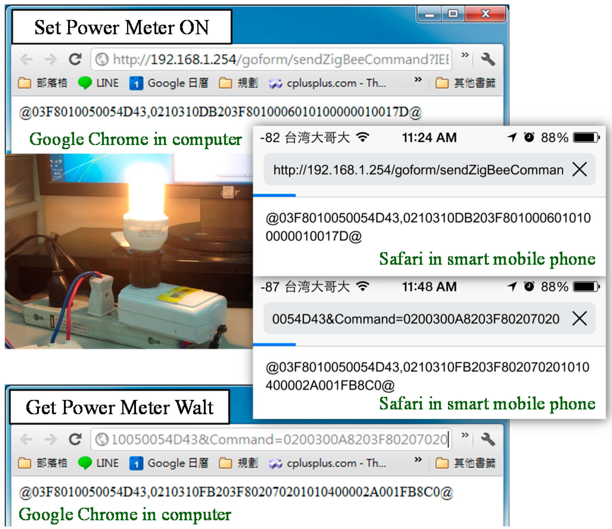
After that, this paper further verifies the command exchange by using HTTP. That is, any web browser, including Google Chrome, Safari, Internet Explorer, or Firefox, can be used to input and subsequently send commands. If the command was executed, as shown in
Figure 11, the results, including device type, IEEE address, network address, and device name, are displayed on the browser.
Figure 11.
Using HTTP to send and return commands.
Figure 11.
Using HTTP to send and return commands.
6. IoT AP Performance Evaluation
To verify the reliability and performance of the proposed IoT AP, this section focuses on the ZigBee response time under dissimilar Wi-Fi environments. The ZigBee response time is defined as the time needed for the IoT AP completes the task of sending the command to the ZigBee devices and receiving the command from the corresponding ZigBee devices.
Table 1 lists the parameters used to verify the existing ZigBee network (IEEE 802.15.4) and Wi-Fi network (IEEE 802.11n). The verification of the response time uses Java verification program, whereas all commands are sent and received by using the TCP method to ensure that the commands are sent to the correct destination.
Table 1.
Simulation Parameters.
Table 1.
Simulation Parameters.
| Parameter | Value |
|---|
| Wireless Protocol | IEEE 802.11n; IEEE 802.15.4 |
| Network Protocol | TCP |
| Channel Variation | Wi-Fi: CH1–CH14; ZigBee: CH11–CH26 |
| Band Variation | Wi-Fi: 2.412–2.484 GHz; ZigBee: 2.405–2.480 GHz |
| SoC Chip | 384 MHz MIPS24Ke |
| Flash Memory | 64 MB |
| Simulation repetitions | 200 |
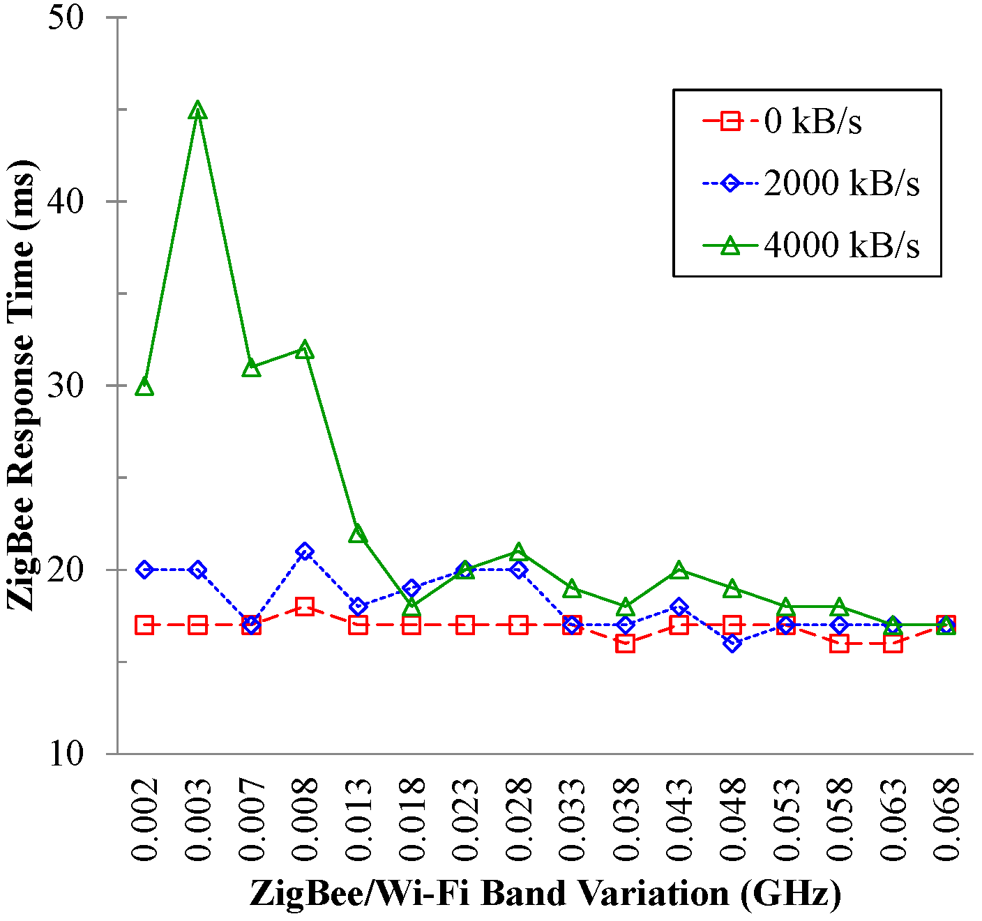
Figure 12 depicts the band variation between various Wi-Fi throughputs (0 KBps, 2000 KBps, and 4000 KBps) and ZigBee response time. The Wi-Fi channel is fixed to CH1 (2.412 GHz) and the ZigBee channel used for testing is changed. The horizontal axis represents the band variation between ZigBee and Wi-Fi (0.002–0.068 GHz) whereas the vertical axis represents the ZigBee response time. As shown in
Figure 12, when the Wi-Fi throughputs are 0 KBps and 2000 KBps, the band variation between ZigBee and Wi-Fi has minimal impact against the ZigBee response time, which is 21 ms. When the Wi-Fi throughput is 4000 KBps, the bands used by ZigBee are closer to the Wi-Fi band, which results in longer response time. Upon the increasing amount of Wi-Fi packets, the probability and number of ZigBee packet collision will be higher. Therefore, some ZigBee packets need to be re-sent, which increases the ZigBee response time. However, the commands can be successfully sent to the ZigBee devices and the average of the response time is still less than 45 ms.
Figure 12.
The impact of ZigBee/Wi-Fi band variation on the ZigBee response time.
Figure 12.
The impact of ZigBee/Wi-Fi band variation on the ZigBee response time.
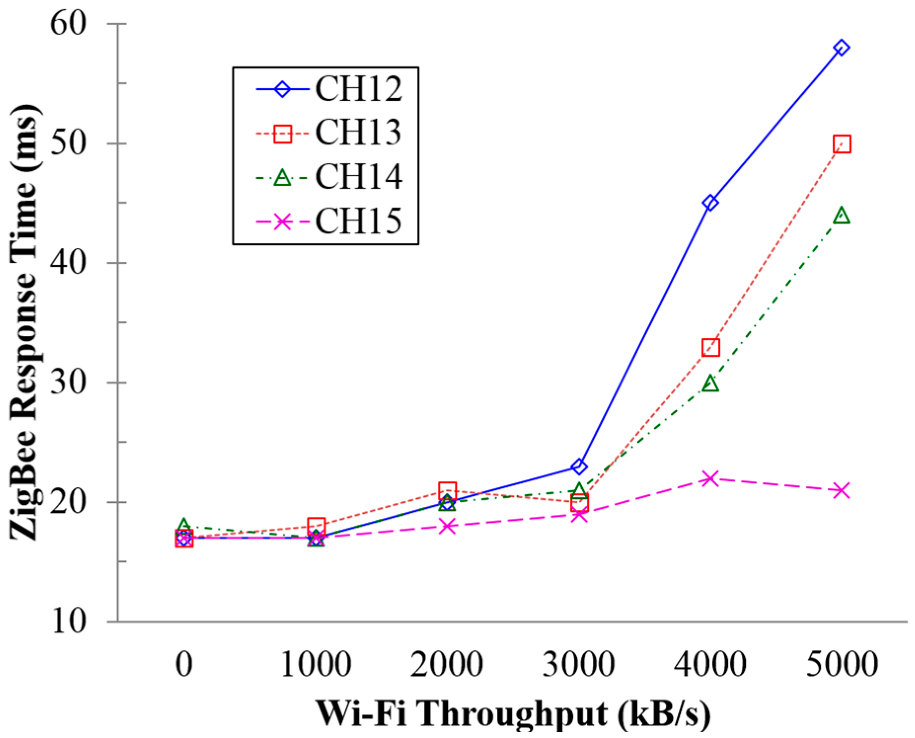
Figure 13 shows the ZigBee response time affected by various Wi-Fi throughputs against various ZigBee channels (CH 11–CH 15). The Wi-Fi channel is fixed on CH1 (2.412 GHz) and the throughput is changed for the test. The horizontal axis represents the variation of Wi-Fi throughputs whereas the vertical axis represents the ZigBee response time. As shown in
Figure 13, when the Wi-Fi throughput ranges between 0 KBps and 3000 KBps, there is a minimal impact on ZigBee response time, which is less than 22 ms. When the Wi-Fi throughput exceeds 3000 KBps, the channels used by ZigBee are closer to the Wi-Fi channels, which results in longer ZigBee response time. The probability and number of ZigBee packet collisions increase with the increment of Wi-Fi packets. Therefore, some ZigBee packets need to be re-sent, which increases the ZigBee response time. From
Figure 13, we can conclude that the response time of ZigBee channel 15 is maintained to be less than 22 ms on any Wi-Fi throughputs.
Figure 13.
The impact of Wi-Fi throughputs variation on the ZigBee response time.
Figure 13.
The impact of Wi-Fi throughputs variation on the ZigBee response time.
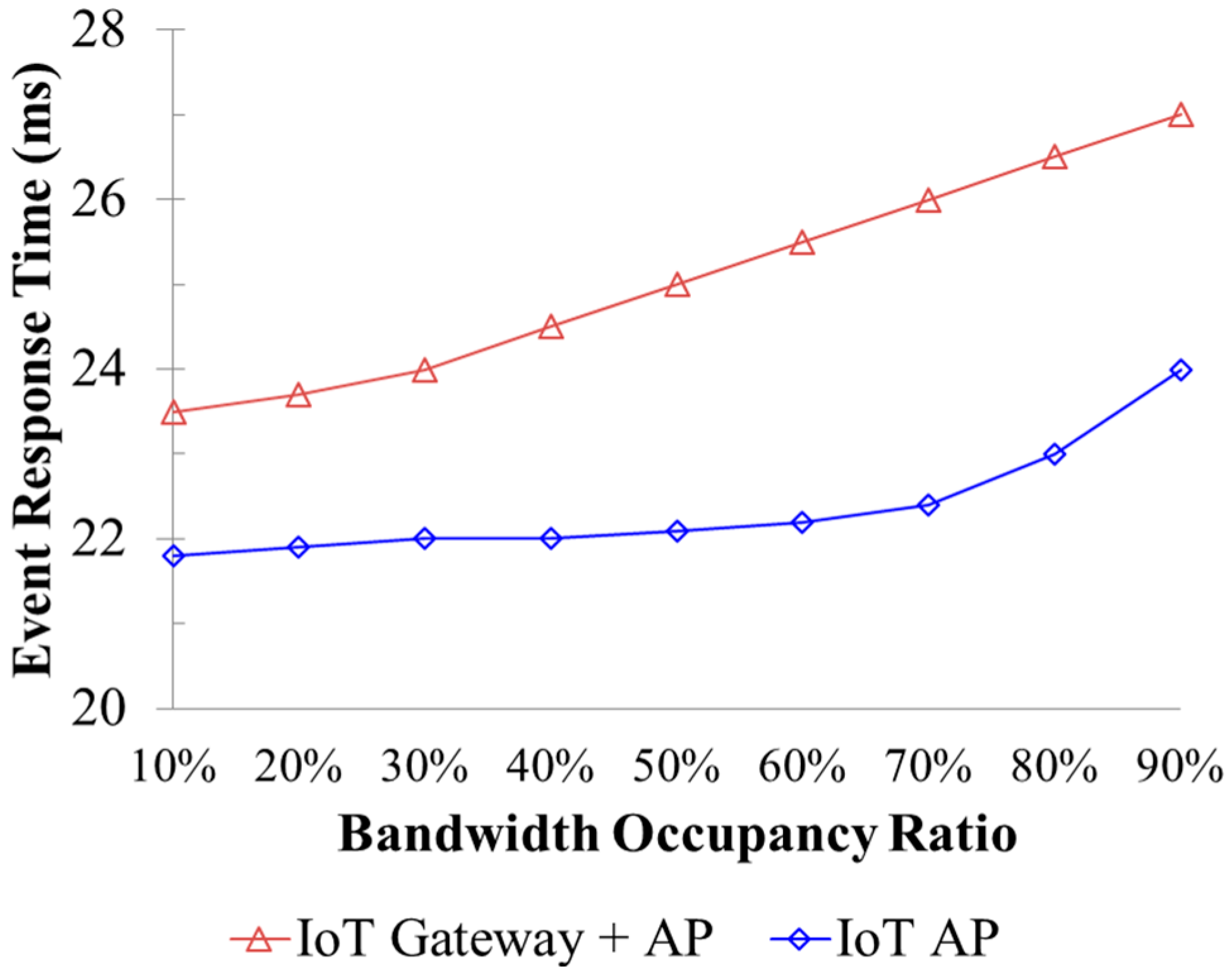
Figure 14 investigates the event response time which is measured by the duration from the time point of event occurrence to the time point that the Internet server has received the event report. The proposed IoT AP is compared with the gateway proposed in [
12]. In [
12], a gateway is designed to collect the sensing data and subsequently forward them to an Internet server via the Wi-Fi AP. Instead, the proposed IoT AP collects data from sensors and subsequently directly forward the data to the Internet server. The two tasks can be accomplished by the internal modules of IoT AP. As shown in
Figure 14, we assigned the IoT device (smart meter) to report its sensing data to the compared gateway and the proposed IoT AP every one hour. The existing bandwidth occupation by Wi-Fi network is set as a percentage ranging from 40% to 90%. The proposed IoT AP outperforms the IoT gateway [
12] in terms of response time. This occurs because that the time required for transmitting data from gateway to the Internet AP has been saved in the proposed IoT AP.
Table 2 shows the measured response time of handheld devices connected to the IoT AP through Wi-Fi connection and using HTTP communication protocol to control the ZigBee devices. The Wi-Fi channel is configured to CH 1 and ZigBee channel is configured to CH 15. Thus, ZigBee and Wi-Fi do not affect each other. As shown in
Table 2, the average time is maintained at about 97 ms and the shortest time period is up to 31 ms. This result occurs because that the CPU performance of RT3052 development board is quite high.
Figure 14.
The impact of bandwidth congestion degree on the IoT device response time.
Figure 14.
The impact of bandwidth congestion degree on the IoT device response time.
Table 2.
Command exchange response time by using HTTP.
Table 2.
Command exchange response time by using HTTP.
| No. | Avg. Time (ms) | Longest Time (ms) | Shortest Time (ms) |
|---|
| 1 | 98 | 1170 | 31 |
| 2 | 97 | 1218 | 31 |
| 3 | 97 | 1264 | 31 |
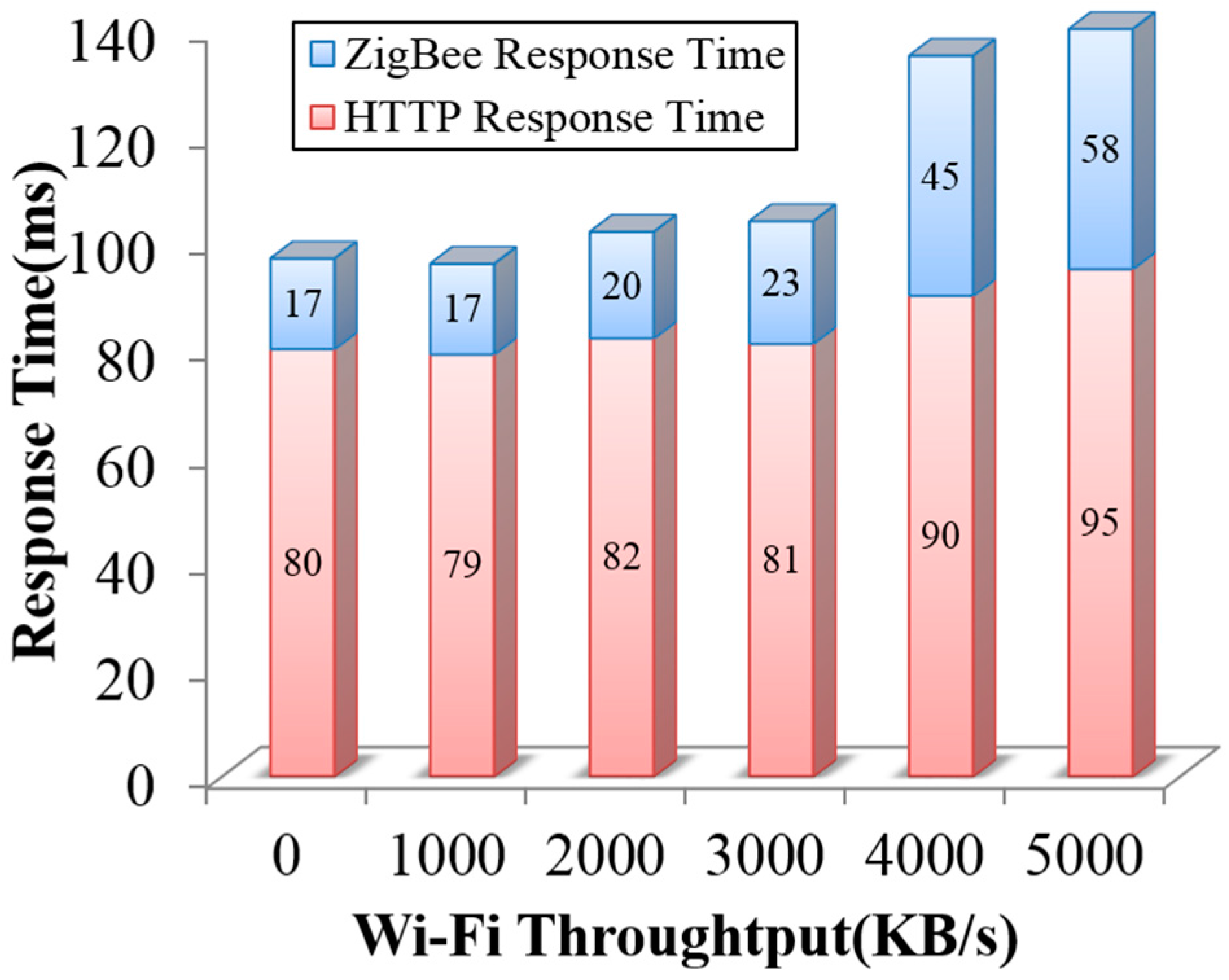
Figure 15 shows the response time of command execution which is sent from a handheld device to the IoT AP through the Wi-Fi network with a variation of Wi-Fi throughputs. The Wi-Fi channel is set to CH 1, whereas the ZigBee channel is set to CH 12. In
Figure 15, the Wi-Fi throughput is varied from 0 to 5000 (KB/s). The horizontal axis represents the variation of Wi-Fi throughputs, whereas the vertical axis represents the sum of HTTP response time and ZigBee response time. As shown in
Figure 15, when the Wi-Fi throughput ranges between 0 KBps and 3000 KBps, the total Wi-Fi response time has minimal impact. When the Wi-Fi throughput exceeds 3000 KBps, the HTTP response time and ZigBee response time are affected by background interference, which results in longer response time.
Figure 15.
The impact of Wi-Fi throughput variation on the command execution response time.
Figure 15.
The impact of Wi-Fi throughput variation on the command execution response time.
To verify the reliability and performance of the proposed IoT AP, this section focuses on the ZigBee response time by varying two parameters, including the ZigBee/Wi-Fi band variation and the Wi-Fi throughput. Based on a number of simulations, it is observed that the lower probability of packet collisions can improve the ZigBee response time. To minimize the interference affected from Wi-Fi, the developed IoT AP can automatically detect the channels occupied by APs and other Wi-Fi devices and subsequently notify ZigBee device management module for determining the optimal communication channel for establishing a ZigBee network with low interference. The proposed channel configuration allows Wi-Fi and ZigBee to function independently with no issue. Finally, when the proposed IoT AP controls the ZigBee devices, it has a relatively short HTTP response time.
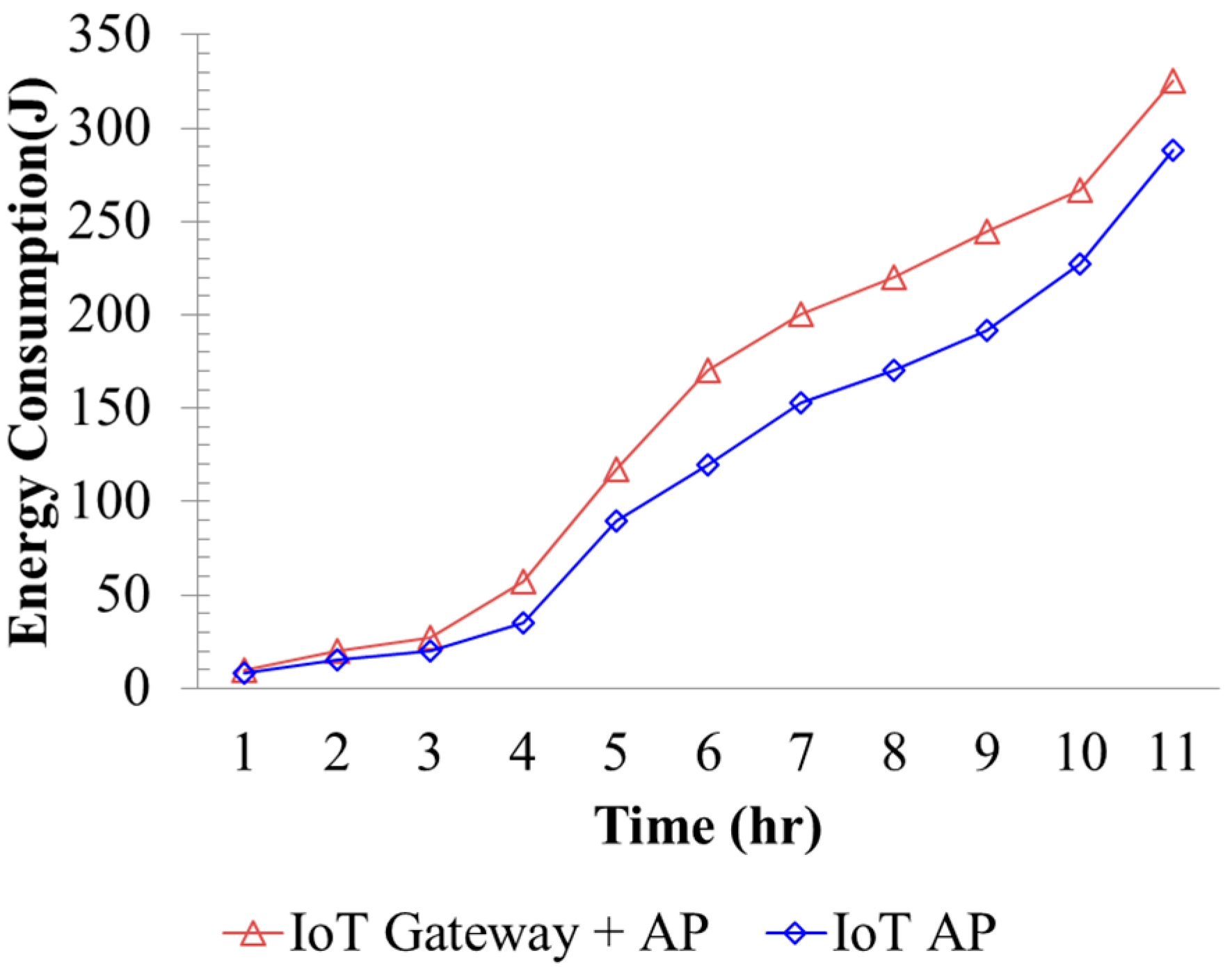
Figure 16 investigates the energy consumptions of the proposed IoT AP and the existing product which is composed by an IoT gateway and a Wi-Fi AP. Because the hardware and firmware components can be highly integrated in the proposed IoT, the energy consumptions can be saved accordingly. Most existing systems [
12,
24] require the IoT devices firstly transmitting data to IoT gateway and, subsequently, the gateway further forwards the data to the AP. This method raises additional energy consumption for data exchange between the IoT gateway and the AP. As shown in
Figure 16, the proposed IoT AP can reduce about 12% off energy than the IoT gateway and AP.
Figure 16.
Comparison of energy consumption.
Figure 16.
Comparison of energy consumption.


