1. Introduction
Recently, there has been increasing research on segmented robots to mimic the peristaltic or serpentine motions and soft bodies of segmented animals. The developments of the miniaturized segment robots or ambulatory micro-robots have been applied to medical endoscopes, rescue robots, hazardous environment exploration, and industrial inspection systems [
1,
2,
3].
The segmented or miniaturized robots can be classified according to actuation devices. In general, electromagnetic actuators have many advantages such as fast response, simple control law, and low manufacturing cost compared with the other actuators [
4,
5]. A solenoid has been widely used among electromagnetic actuators because it has a simple structure and both the direction and magnitude of the electromagnetic force can be easily controlled by changing the input current applied to the solenoid. The conventional solenoid uses a long loop of wire wrapped around a metallic core (plunger), and it produces a magnetic field to generate the linear motion of the plunge when an electric current is passed through the wire coil. Linear solenoids can be either unidirectional or bi-directional (push and pull) and they often have a spring return to bring the plunger back to the home position. Metallic plungers have often been replaced by a permanent magnet plunger to increase the electromagnetic force and response. Various solenoid actuators of bi-directional motions equipped with movable permanent magnets have been developed over a few decades [
6,
7]. Recently, Bammesberger
et al. [
8] and Kartmann
et al. [
9] have developed miniaturized solenoids with a ferromagnetic plunger for the application to disposal dispensing valves.
In a previous work [
10], we designed a four-segmented robot using solenoids mimicking the earthworm’s locomotion, where the segmented robot has a high-speed rectilinear motion. However, the miniaturized robot with turning locomotion has not been implemented. As the extension of the linear motion in the previous work [
10], we design and develop a miniaturized solenoid with a ferromagnetic plunger to generate both rectilinear and turning motions of the segmented robot. We implement the theoretical analysis on the actuation force induced by the solenoid with a magnetic plunger based on the Biot-Savart law. Next, the design parameters of the solenoid for the miniaturized robot are determined using an optimization method. Experiments on the linear and turning motions are implemented and compared with the theoretical analysis using a prototype of the two-segmented robot equipped with a pair of solenoids.
2. Solenoid Design and Analysis
The objective of this research is to design and develop a solenoid for miniaturized segment robots with linear and turning motions.
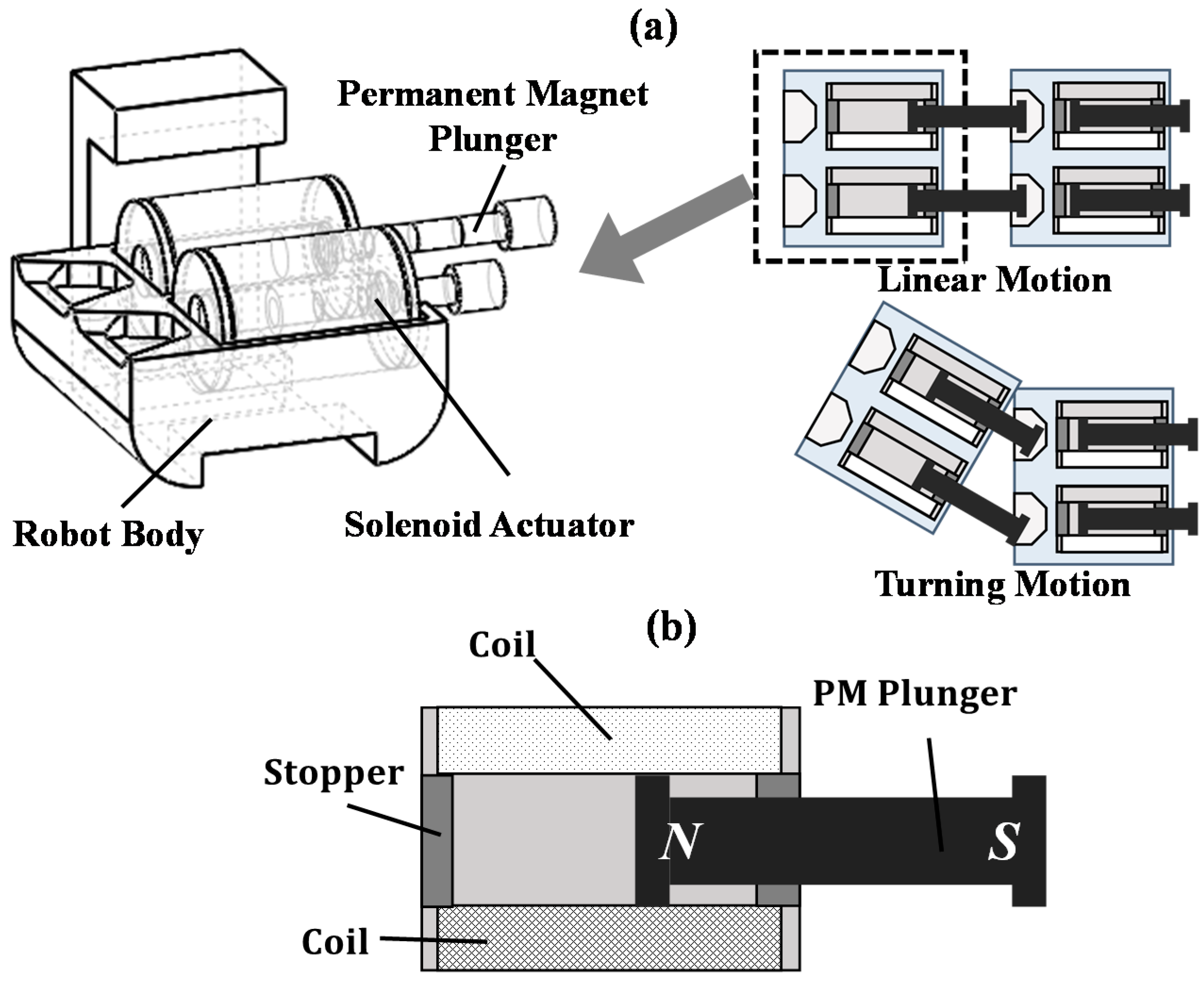
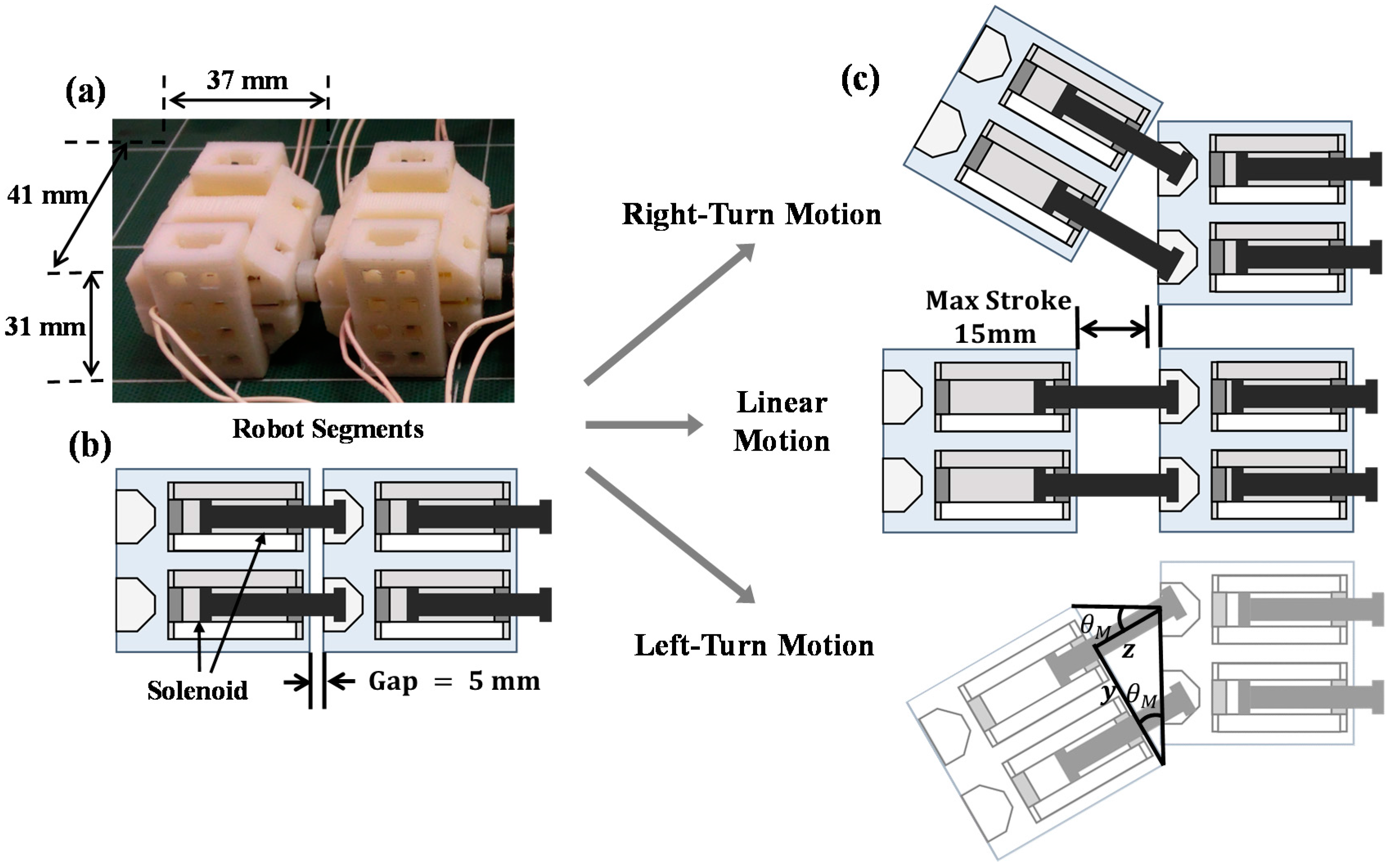
Figure 1a shows the design of the proposed robot with two segments. Each segment is actuated by a pair of solenoids to enable both linear and turning motions. The segmented robot has the rectilinear motion by actuating the solenoid pair in the same direction. Also, it can change direction by making the solenoid pair move in the opposite direction against each other. Moreover, to develop miniaturized segment robots, we have to reduce the size of a solenoid, on the one hand, and achieve an electromagnetic force strong enough to actuate each segment, on the other. In this chapter, we design and propose a solenoid based on the theoretical analysis.
Figure 1.
The design of a solenoid with a permanent magnet (PM) plunger: (a) the design concept of multi-segment robots with linear and turning motions using a pair of solenoids; (b) the cross-sectional view of the proposed solenoid actuator with PM plunger.
Figure 1.
The design of a solenoid with a permanent magnet (PM) plunger: (a) the design concept of multi-segment robots with linear and turning motions using a pair of solenoids; (b) the cross-sectional view of the proposed solenoid actuator with PM plunger.
2.1. Solenoid Structure
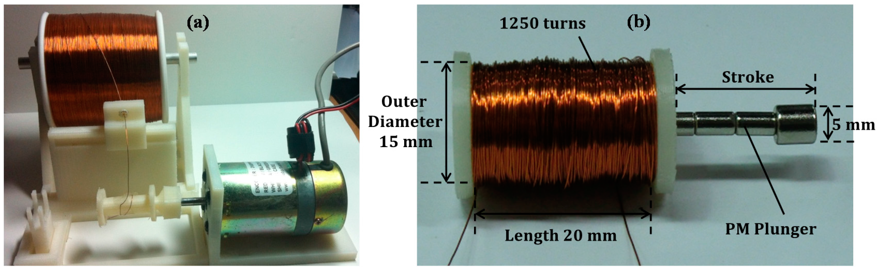
The proposed solenoid consists of a coil and a movable plunger as shown in
Figure 1b. The electromagnetically inductive coil is wound around the plunger. We use a permanent magnet (PM) as a plunger, rather than generally used metal rods, to generate a higher actuation force. Therefore, two kinds of forces are exerted in the solenoid. One is the electromagnetic force induced by the magnetic field inside the solenoid when a current flows into wound coils. The other is the magnetic force caused by a permanent magnet plunger.
2.2. Theoretical Analysis
The theoretical analysis on the electromagnetic force generated by the solenoid is implemented to design a solenoid actuator with a permanent magnet plunger. We develop a new type of solenoid actuator for bi-directional motion in the miniaturized robot. This solenoid actuator has a simple structure composed of coils and a permanent magnet plunger. The resultant force by the solenoid depends on the length, air-gap, number of coil turns, applied current, and the type of permanent magnet, etc. We induce the equation of electromagnetic force actuated by the solenoid as the functions of these design variables to develop a suitable solenoid for segmented robots.
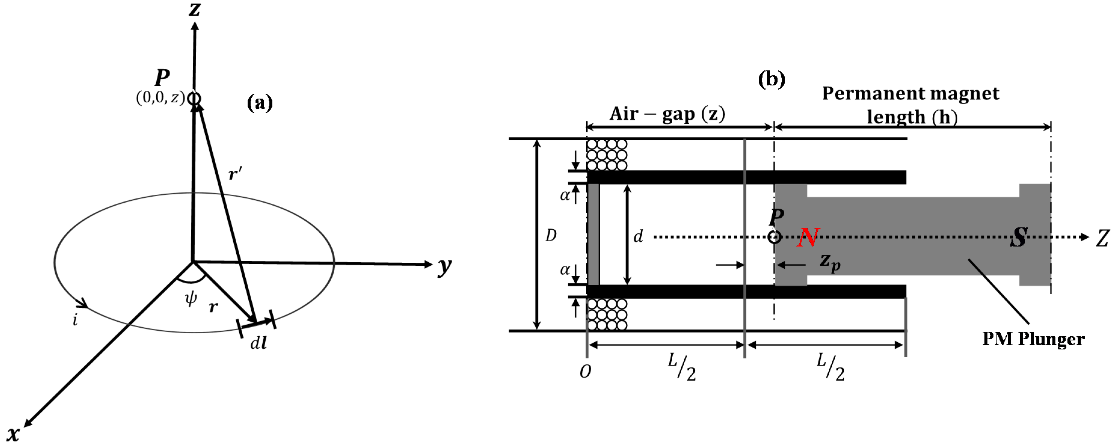
The magnetic field along the axis of a circular current loop of radius
r and steady current
can be expressed by the Biot-Savart law in
Figure 1a:
Here,
and
are the line segment and distance vector from the viewpoint to the source charge;
represents the permeability of vacuum. By the use of
,
and
, the magnetic field
at an arbitrary point
on the axis of the current loop becomes
Figure 2b shows the cross-sectional view of the solenoid actuator. In particular, for currents with special symmetry, Ampere’s law in integral form offers an extraordinarily efficient means for finding the electromagnetic field. The axial electromagnetic field of the solenoid is obtained by Equation (2). Using the design parameters of the solenoid actuator such as inner diameter
, outer diameter
, number of coil turns
, and length
, Equation (2) becomes
Figure 2.
The solenoid dimensions for the electromagnetic analysis: (a) one turn of coil flowing with current i; (b) the cross-sectional view of a solenoid with PM plunger and design parameters.
Figure 2.
The solenoid dimensions for the electromagnetic analysis: (a) one turn of coil flowing with current i; (b) the cross-sectional view of a solenoid with PM plunger and design parameters.
Here,
and
represent the wounded coils per unit length and the distance of point
from the center of the solenoid;
is the moving distance of the PM plunger inside the solenoid or the length of the air-gap. By the integration of Equation (3), the electromagnetic field at point
becomes
The electromagnetic force
acting on the permanent magnet plunger by the solenoid actuator can be expressed as [
11]
Here,
is the external magnetic field produced by the wounded coils. The direction of external magnetic field
equals that of magnetic flux
, and its magnitude is calculated by Equation (4). It is assumed that the magnet has a fixed and uniform magnetization (
) in the direction of the longitudinal axis of the solenoid. Since the unit surface normal vector
=
at z = 0 and
=
at z = h, the surface charge density
is calculated as
Only the north pole of the permanent magnet is located in the field of the solenoid. Since the uniform magnetization
has no divergence, it has
where
represents the remanent flux density or remanence occurred by the permanent magnet plunger. Also, the magnetic volume charge density
[
11], then, finally, the electromagnetic force is
Here, is the area by the inner diameter of the solenoid. The electromagnetic force is proportional to the magnetic field of the solenoid actuator () and the magnetic plunger (). Using Equation (7), the electromagnetic force is evaluated analytically or numerically. In this theoretical analysis, the magnetic circuit is regarded as ideal, where the magnetic fringe and leakage were ignored.
2.3. Solenoid Design
Equation (7) shows that the electromagnetic force from the solenoid actuator is proportional to the change in inductance of the coil with respect to the change in the position of the PM plunger as well as the current flowing through the coil. The solenoid force depends on various design parameters such as the inner and outer diameters of the solenoid, the number of coil turns, the air-gap, solenoid length, input current, and the remanence of the permanent magnet. We determine the optimal design parameters of the proposed solenoid for the segmented robots. Each segment is actuated by a pair of solenoids to enable both linear and turning motions. In order for the solenoid to actuate each segment, the pushing or retracting force of the solenoid is required to overcome the friction force of each segment.
To determine the design parameters of the solenoid, we fix the mass of each segment at m = 60 g for the light robot body. We use a ferromagnetic material (NdFeB) for the PM plunger. Then the total electromagnetic force of each solenoid is set to have = 0.6 N, which is larger than the friction force (). Secondly, we have also fixed the following parameters: the current applied to the coil (i = 0.6 A), the air-gap from the center of solenoid ( = 0), the diameter of the wire (0.2 mm), and the remanence of the PM (4000 Gauss).
Then, we determine the optimal values of the following design parameters: the number of coil turns
N, the solenoid length
L, and the inner diameter
d of the solenoid. The outer diameter of solenoid
D is calculated by the relation among the solenoid length
L, diameter of the wire (0.2 mm), the number of coil turns
N, and the solenoid inner diameter
d. Using the commercial software MATLAB (MathWorks Inc., Natick, MA, USA), we calculate the electromagnetic force of the solenoid given by Equation (7).
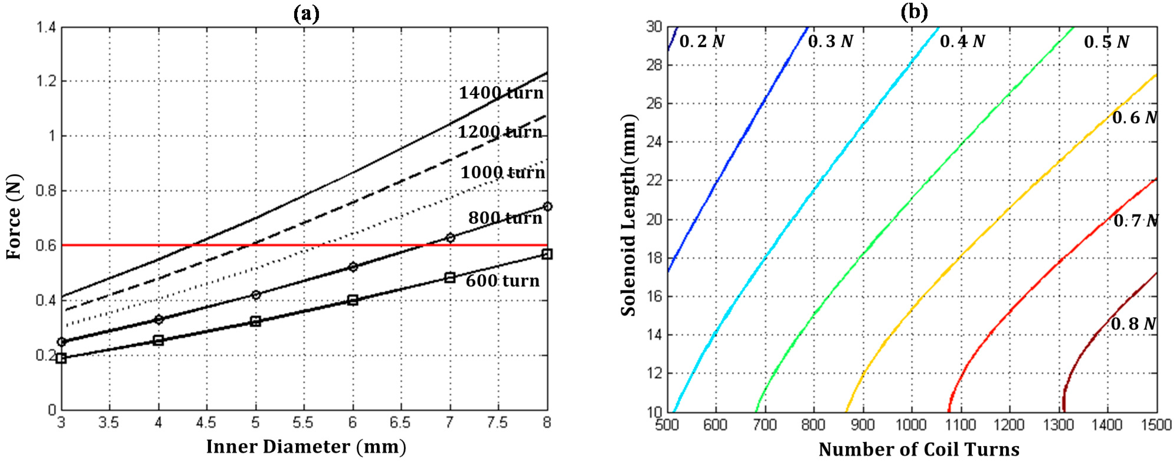
Figure 3a,b show the solenoid forces for different inner diameters and numbers of coil turns, and the force distribution depending on the solenoid length and number of coil turns, respectively. Finally, the solenoid length (
L = 20 mm), the number of coil turns (
N = 1250 turns), and the inner diameter (
d = 5 mm) are determined for the solenoid to actuate the segmented robot.
Figure 3.
The theoretical analysis of the solenoid force: (a) the solenoid force for different inner diameters and numbers of coil turns at the solenoid length of 20 mm; (b) the distribution of the solenoid force depending on the solenoid length and number of coil turns at the inner diameter of 5 mm.
4. Experiments and Discussions
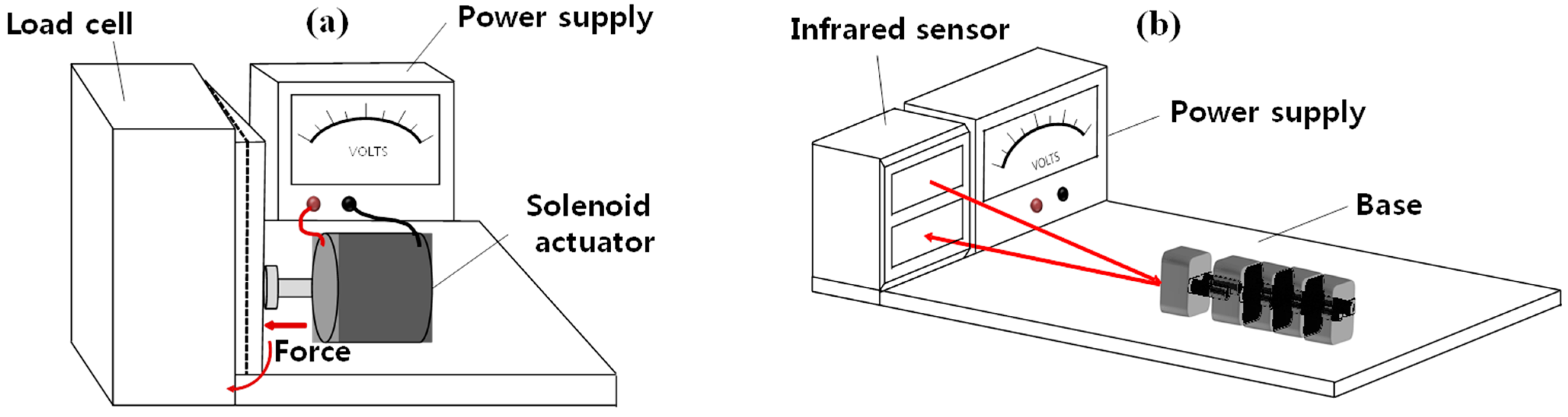
We set up the experimental apparatus to measure the force and the displacement by the solenoid actuator to examine the performance of this solenoid actuator. As shown in
Figure 6a, we construct an experimental set-up to measure the force generated by the solenoid using a load cell (CASTM PW4MC3, HBM, Darmstadt, Germany) the fixture to hold the solenoid, and the power supply. We use an infrared sensor (2Y0A02, Sharp Corporation, Osaka, Japan) as shown in
Figure 6b to measure the displacement of the segmented robot. The distance measuring range of the infrared sensor system is from 20 to 150 cm. Additionally, the tolerance of this sensor system is approximately 0.3 mm.
Figure 6.
Experimental apparatus: (a) the measurement of the output force by the solenoid actuator; (b) the displacement measurement of the segmented robot using an infrared sensor.
Figure 6.
Experimental apparatus: (a) the measurement of the output force by the solenoid actuator; (b) the displacement measurement of the segmented robot using an infrared sensor.
Table 1 shows the theoretical and experimental results of electromagnetic forces acting on the PM plunger by the solenoid at the center of the solenoid (
= 0), using the optimal design parameters: the solenoid length (
L = 20 mm), the number of coil turns (
N = 1250 turns), and the inner diameter (
d = 5 mm). The experiments are performed 10 times and the averaged values are compared to the theoretical ones. The theoretical forces are calculated using Equation (7) for various numbers of coil turns, from 1100 to 1600 turns, at the constant input current (±0.6 A). The resistance of the proposed solenoid actuator is about 20 ohms. The experimental pushing and pulling forces are measured while changing the turns of wounded coils and the direction of the constant current. The electromagnetic force by the solenoid depends on the positions of the solenoid and the plunger. The theoretical results show that the pushing and pulling forces are the same at the constant input current. However, the experimental results indicate that the pushing and pulling forces are slightly different when the input current is reversed. The proportional dependence of the solenoid-induced force increasing on the coil turns is similar in both theory and experiments.
Table 1.
The pulling and pushing electromagnetic forces from the solenoid actuator and the comparison of theoretical forces with experimental results for various coil turns.
Table 1.
The pulling and pushing electromagnetic forces from the solenoid actuator and the comparison of theoretical forces with experimental results for various coil turns.
| No. of Turns of Coils | Theoretical Force (N) | Experimental Force (N) |
|---|
| Pushing | Pulling | Pushing | Pulling |
|---|
| 1100 | 0.5644 | 0.5664 | 0.5335 | 0.5077 |
| 1200 | 0.6104 | 0.6104 | 0.6036 | 0.5881 |
| 1300 | 0.6554 | 0.6554 | 0.6392 | 0.6580 |
| 1400 | 0.6996 | 0.6996 | 0.6557 | 0.6926 |
| 1500 | 0.7429 | 0.7429 | 0.7082 | 0.7906 |
| 1600 | 0.7854 | 0.7854 | 0.7659 | 0.8370 |
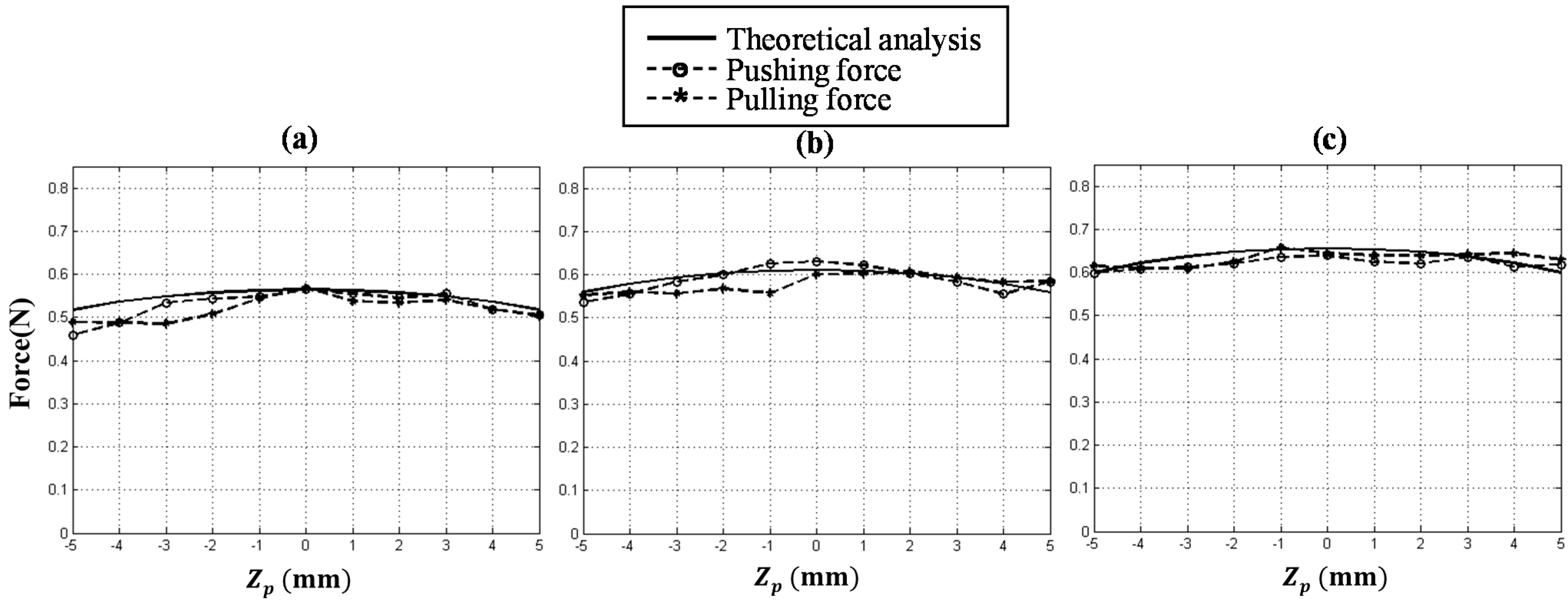
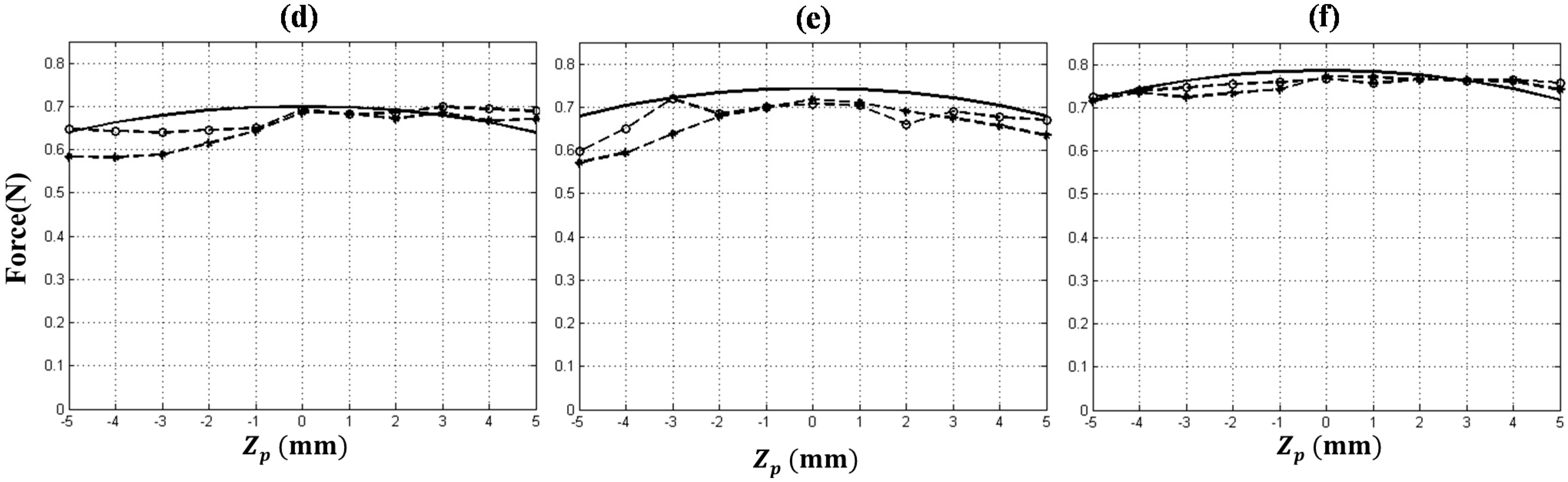
The theoretical electromagnetic forces from Equation (9) and the experimental data are plotted in
Figure 7 for various coil turns when the plunger positions are changed from
= −5 to 5 mm at the center of the solenoid.
Figure 7a–f represent the pushing and pulling forces for six cases of coil turns: 1100, 1200, 1300, 1400, 1500, and 1600 turns. Other variables are fixed for the experiments such as the current applied to the coil (
i = 0.6 A), the diameter of coil (0.2 mm), the solenoid length (
L = 20 mm), and the remanence of PM (4000 Gauss). The electromagnetic force from the solenoid also depends on the positions of the solenoid and the plunger. The dashed circle and dashed star lines in the graphs indicate the experimental pushing and pulling electromagnetic forces, respectively. As mentioned in
Table 1, the theoretical pushing and pulling forces are the same.
Figure 7.
The resultant magnetic forces as a function of the plunger position zp from the solenoid center for various coil turns: (a) 1100 turns; (b) 1200 turns; (c) 1300 turns; (d) 1400 turns; (e) 1500 turns; (f) 1600 turns.
Figure 7.
The resultant magnetic forces as a function of the plunger position zp from the solenoid center for various coil turns: (a) 1100 turns; (b) 1200 turns; (c) 1300 turns; (d) 1400 turns; (e) 1500 turns; (f) 1600 turns.
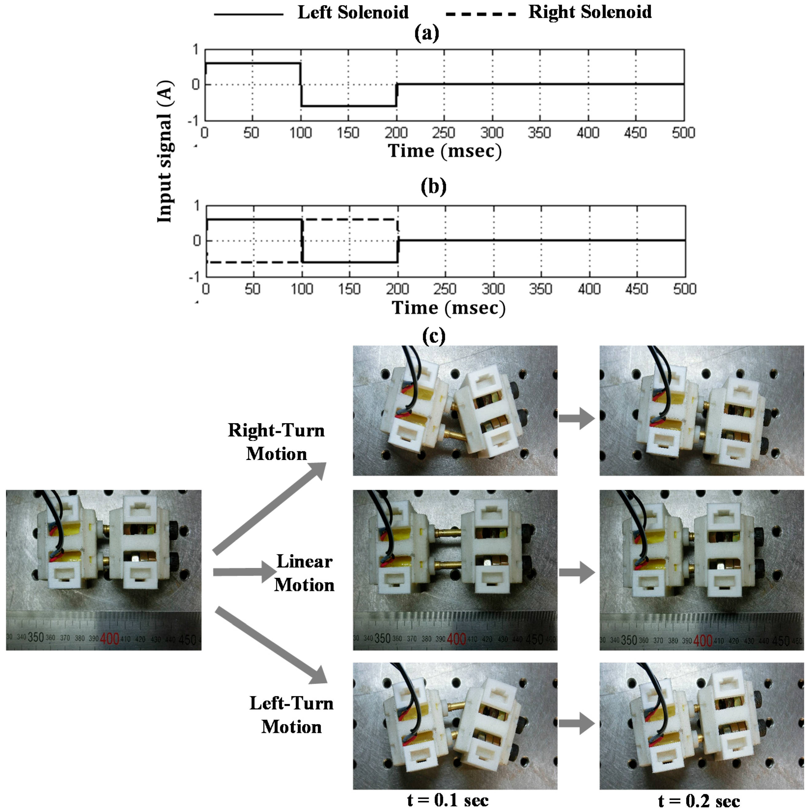
Figure 8a,b show the time profiles of the input currents applied to the left and right solenoids of the segmented robot for the linear and right-turning motions, respectively. To generate the linear motion, the current signals of ±0.6 A are applied to a pair of solenoid actuators, and then these signals actuate the pair of PM plungers at the same time. For the turning motion, reverse input signals are applied to the pair of solenoids, indicating the solid and dashed lines of the graph.
Figure 8c shows the photos of the experimental results when the solenoid pair is actuated for the linear and right/left-turning motions over 0.2 s. We measure the displacement of the front segment moving on the surface with kinetic frictional coefficient
= 0.2 using an infrared sensor (2Y0A02, Sharp Corporation, Osaka, Japan). The captured images over a cycle are shown in
Figure 8c. It takes 0.1 s to move one segment and 0.2 s for two segments to complete the linear motion over one cycle. For the rectilinear motion, both plungers of the solenoid pair drive the first segment in the same direction. However, unwanted backward or slip motion occurs between two segments. It is because the back segment is not weighty enough to keep stationary during expansion (0 <
t < 0.1 s) and the front segment has a backward motion during contraction (0.1 <
t < 0.2 s). We measure the linear displacement over 10 cycles and the averaged displacement becomes 4.9 mm. The experimental displacement over the cycle is smaller than the theoretical one which is the plunger stroke of 15 mm. For the turning motion, the solenoid pair moves in the opposite direction from each other to generate an asymmetrical force. The experimental angular displacement (1.84 degrees) is lower than the theoretical one of
= 8.82 degree from Equation (8) due to the backward or slip motion between the two segments.
To evaluate the effect of friction between the surface and the segmented robot, we implement experiments for the four cases of
= 0.2, 0.35, 0.5, and a fixed condition holding the back segment stationary. We measure the linear and turning motions over 10 cycles for the four cases and the results are summarized in
Table 2. The discrepancy between the theory and experiments decreases with the increasing friction coefficient. The preliminary experiments using two segments can be extended to multi-segmented robots by attaching additional segments with a pair of solenoids.
Figure 8.
Profiles of input currents applied to the solenoid pair of the segmented robot (a) for the linear motion; (b) for the right-turning motion; (c) the captured images of the linear and right/left-turning motions of the two segments at 0.2 s.
Figure 8.
Profiles of input currents applied to the solenoid pair of the segmented robot (a) for the linear motion; (b) for the right-turning motion; (c) the captured images of the linear and right/left-turning motions of the two segments at 0.2 s.
Table 2.
Linear and angular displacements of the two-segmented robot for various friction conditions: the comparison of theoretical values with experimental results.
Table 2.
Linear and angular displacements of the two-segmented robot for various friction conditions: the comparison of theoretical values with experimental results.
| | Theory | Experiment |
|---|
| μk = 0.2 | μk = 0.35 | μk = 0.5 | fixed |
|---|
| Linear displacement (mm) | 15 | 4.9 | 8.1 | 8.6 | 14.3 |
| Angular displacement (deg) | 8.82 | 1.84 | 2.66 | 2.81 | 7.97 |


