1. Introduction
In recent decades, wind energy has become the predominant viable source of renewable energy. Scientists and engineers have gained vast experience in handling small to large capacity generation system. Wind power generation is also estimated to produce 12% of the world’s electricity requirement by 2020 [
1]. Since wind is varying in nature, a wind turbine generation unit does not take into consideration the changing load power demands [
2,
3]. Therefore, it is very important to develop a power management system for handling power generation, to effectively match the varying load demand and increase the life of turbines. Most of the modern wind farm management systems ensure maximum yields and increased service life of wind farms. A power management system for wind power generation communicates with sophisticated control systems to respond to changing load demands. Passive stall control, variable pitch control and active stall control are the major control systems employed in regulating the power captured by the turbine rotor. But, with increasing machine size and power production capacity, the modern trend is towards using pitch control and active stall control for power regulation. [
4,
5,
6,
7]. Also, variable pitch control methods can achieve better power regulation and lower dynamic loads on wind turbines [
8,
9]. In a pitch regulated wind turbine, the power captured by the rotor is regulated for achieving two targets: (1) Maximize energy captured by pitching the blades at optimum angle towards the wind for above rated wind speeds; and (2) Avoid excessive power generation by pitching to feather,
i.e., optimally positioning blades away from wind direction to ensure mechanical limitations are not exceeded for wind speeds above the cut-in speed of turbines.
A power management system can control the power generation at optimum levels to meet the load power demand [
10]. It can provide adequate energy based on the load demand and the availability of energy from the wind turbine. In the case of high energy production, the load demand can be completely or partially satisfied based on the supervisor request, who has the priority in making the decision by the power management system. In order to handle the situation during low energy production, load power demand management schemes have been employed by many distribution utilities [
11], were the HVAC (heating, ventilation and air- conditioning) loads can be switched off during peak conditions or during emergency situations with limited controllability.
The power management system changes the amount of the requested and provided power during its operation. Therefore, this power must be regulated to track a power profile requested by the supervisor. The pitch angle controller can adjust the pitch setting at its optimum value to achieve power tracking [
12,
13,
14]. A control strategy has been investigated in [
15] to maintain balance between produced energy and load demand, and a multivariable control strategy used in [
16] regulates the pitch angle and electrical load to control the wind turbine speed. However, the regulation of power through the pitch angle can cause high activity of the pitch actuator due to small fluctuations in the power during steady state operation, which can affect the flow of power to the load.
In this paper, a Boolean-based power management system is developed for supplying a set of load banks from wind energy sources. It is designed for an automatic switching of the banks depending on the request of a supervisor, the availability of power from wind, and the banks’ priorities. The supervisor can manually turn the banks’ ON-OFF switches, and a power reference signal is generated based on the switches being at state ON, which is used as a reference to control the wind turbine power output. A pitch angle control strategy is used to regulate the power through the pitch actuator, the only control system available in the wind turbine, as there is no power electronic interface between the generator and the load to allow controlling the wind turbine outputs.
A modified PI pitch angle control is proposed to reduce fluctuation in the power, reduce activity of the pitch actuator and maintain a consistent brilliance of the banks’ LEDs. In case of excess wind power compared to the power reference, as requested by the supervisor, the pitch actuator of the wind turbine will change the pitch angle of the blades to reduce the generated power to the reference one. For the other case, where the wind turbine cannot produce enough power to meet the demand of the supervisor, less priority loads will be automatically turned OFF by the automatic power management system. The Boolean-based method presented in this work can be applied for a small-scale network with a limited number of isolated loads and can be used in remote areas where less demand of energy is required.
The rest of the paper is organized as follows: the experimental setup (wind turbine and electronic load) is described in
Section 2; the proposed power management system for automatic switching of the banks is detailed in
Section 3; the modified pitch angle controller, to deal with power fluctuation, is analyzed in
Section 4; And, the experimental results are presented in
Section 5.
3. Automatic Power Management System
3.1. Logic Development of Automatic Switching
The aim of the automatic switching system is to manage the distribution of power to the banks based on the available power from wind and the power demand by the banks. A supervisor is changing the power demand by manually turning the banks’ switches ON/OFF, and the automatic switching system will make the decision of turning the banks’ switches ON/OFF based on the generated power and some conditions related to power demand.
The design of the logic for the priorities of the banks’ automatic switching is based on the following conditions:
(1) The number of banks turned ON will be determined by the power generated from the wind turbine.
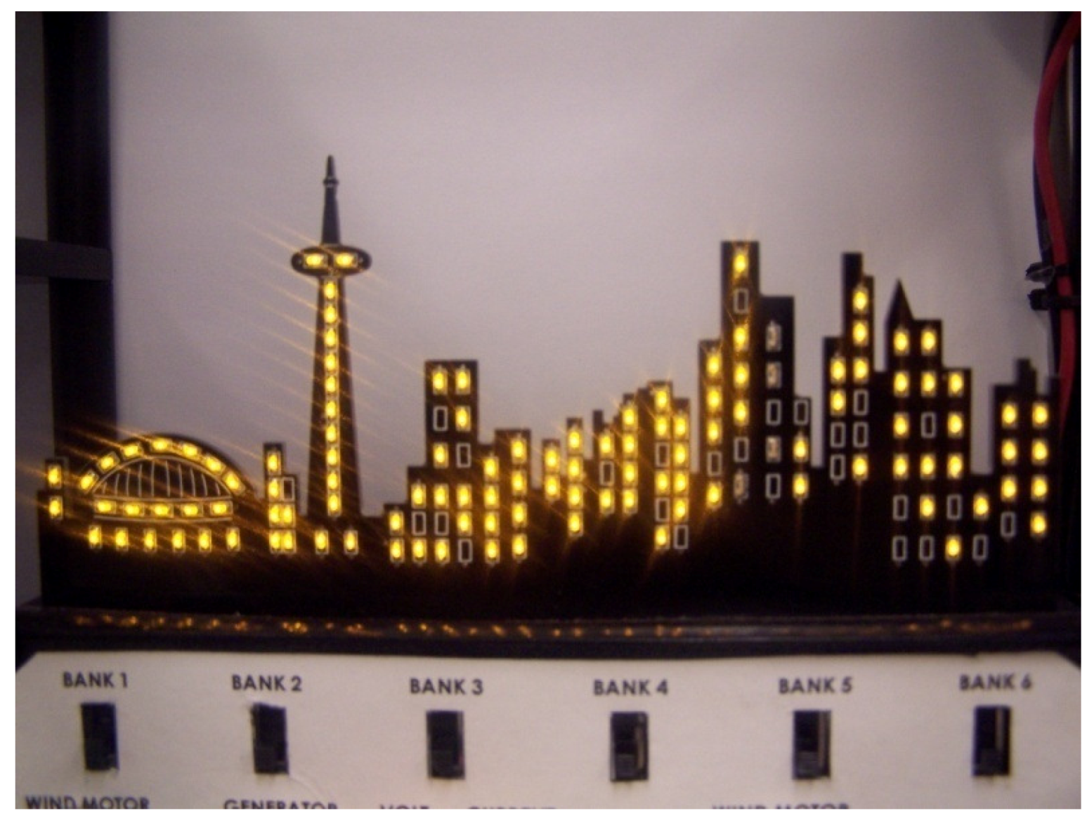
(2) A bank is considered to be ON if it is illuminated without flickering and with minor power fluctuation.
(3) Based on the amount of generated power, the banks are ranked by priority from the left to the right in the load (Bank 1, Bank 2, … and Bank 6). However, the priorities can be assigned to different banks by switching wires into the multiplexer.
(4) A supervisor can manually turn ON/OFF any bank (i.e., if Bank 3 is manually turned OFF, less power should be required to turn Bank 4 ON than if Bank 3 is also ON). In this case, the priority of automatic switching will be based on the captured power from wind and the required power, which will be regulated to follow a power reference by changing the pitch angle of the blades through the pitch actuator and a pitch angle controller.
The signal of the power reference is built based on the state of the manual switches given by the supervisor. The Boolean expressions of the priorities of the banks’ automatic switching are given as follows:
where, all quantities are logic variables (TRUE ≡ ON ≡ 1; FALSE ≡ OFF ≡ 0).
Prn (n = 1:6) is the priority of bank n, which automatically turns it ON/OFF. A, B, C, D, E and F: conditions of the manual switches for the banks (1, …, 6) respectively. –: symbol of the logic NOT. Q, R, S, T, U and V: conditions of the generated power (Pgen) given in the following table.
Table 1.
Conditions of the generated power.
Table 1.
Conditions of the generated power.
| Conditions | Generated power (Pgen) |
|---|
| Q | ≥0.1 W |
| R | ≥0.2 W |
| S | ≥0.3 W |
| T | ≥0.4 W |
| U | ≥0.5 W |
| V | ≥0.6 W |
Table of generated power conditions has been built based on experimentation and observation. Depending on the manual switching of the banks, it is observed that for each bank a power of 0.1 W is required to illuminate the bank’s LEDs and remain bright enough to be considered ON.
3.2. Power Error-Tolerance
The measured power fluctuates around the power reference because of various factors such as random variation of wind speed, noise measurement in sensors and the continuous activity of the pitch actuator. The logic of the automatic switching system is based on constant step changes of the power reference following the supervisor’s request. Therefore, without any power error tolerance around the power reference, the banks will switch ON and OFF each time there is an error between the measured power and reference one as shown in
Table 2.
Table 2.
Switch’s states based on the power error.
Table 2.
Switch’s states based on the power error.
| Error | Bank’s switch |
|---|
| + | ON |
| – | OFF |
| 0 | ON |
It can be seen from
Table 2 that the bank’s switch will automatically go OFF when the available power is smaller than the reference one, which is practically incorrect for a small error because there is sufficient power to illuminate the bank.
In order to overcome this problem, an error-dependent threshold for automatic bank switches can be added to the logic of the automatic switching system. The appropriate power threshold
Ptr is the lower end of acceptable power for the number of manually switched ON banks. The added logic subtracts the programmed allowable error from the original threshold as
where
Pref is the power reference based on the number of banks manually switched ON by the supervisor, and
ε is the error tolerance.
The acceptable power range
Pa for the number of banks ON is given by
Therefore, if the generated power Pgen is changing in the range of Pa, the automatic switch(s) is (are) considered ON and the bank(s) is (are) illuminated.
4. Modified Pitch Angle Controller for Power Regulation
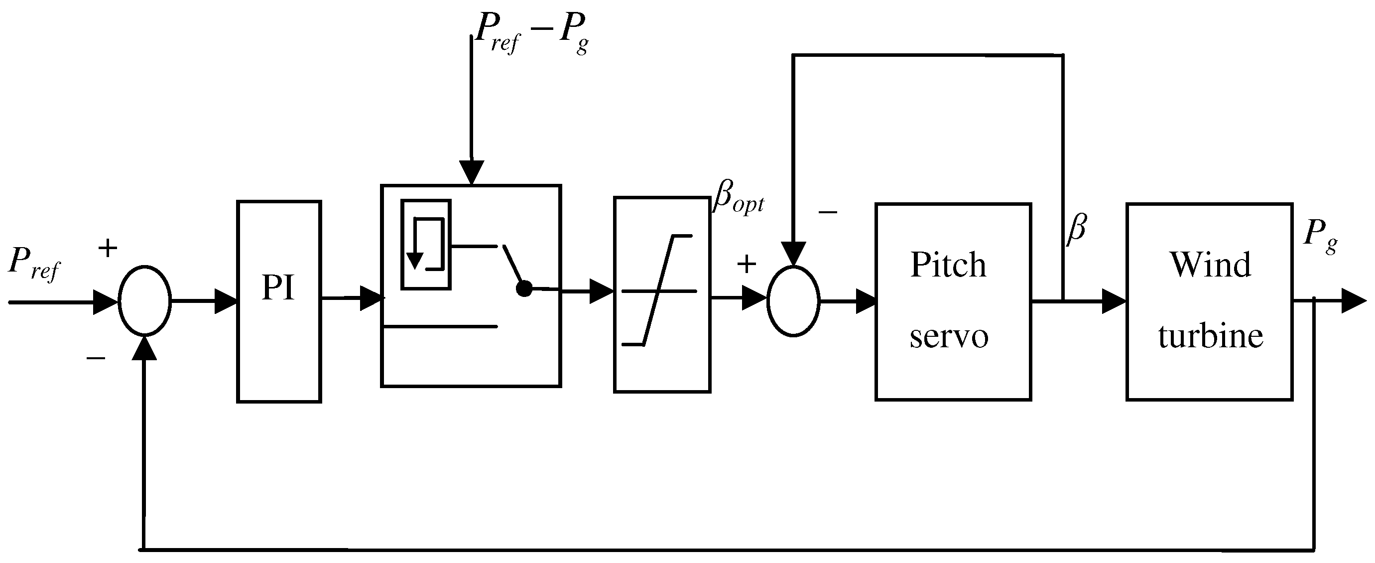
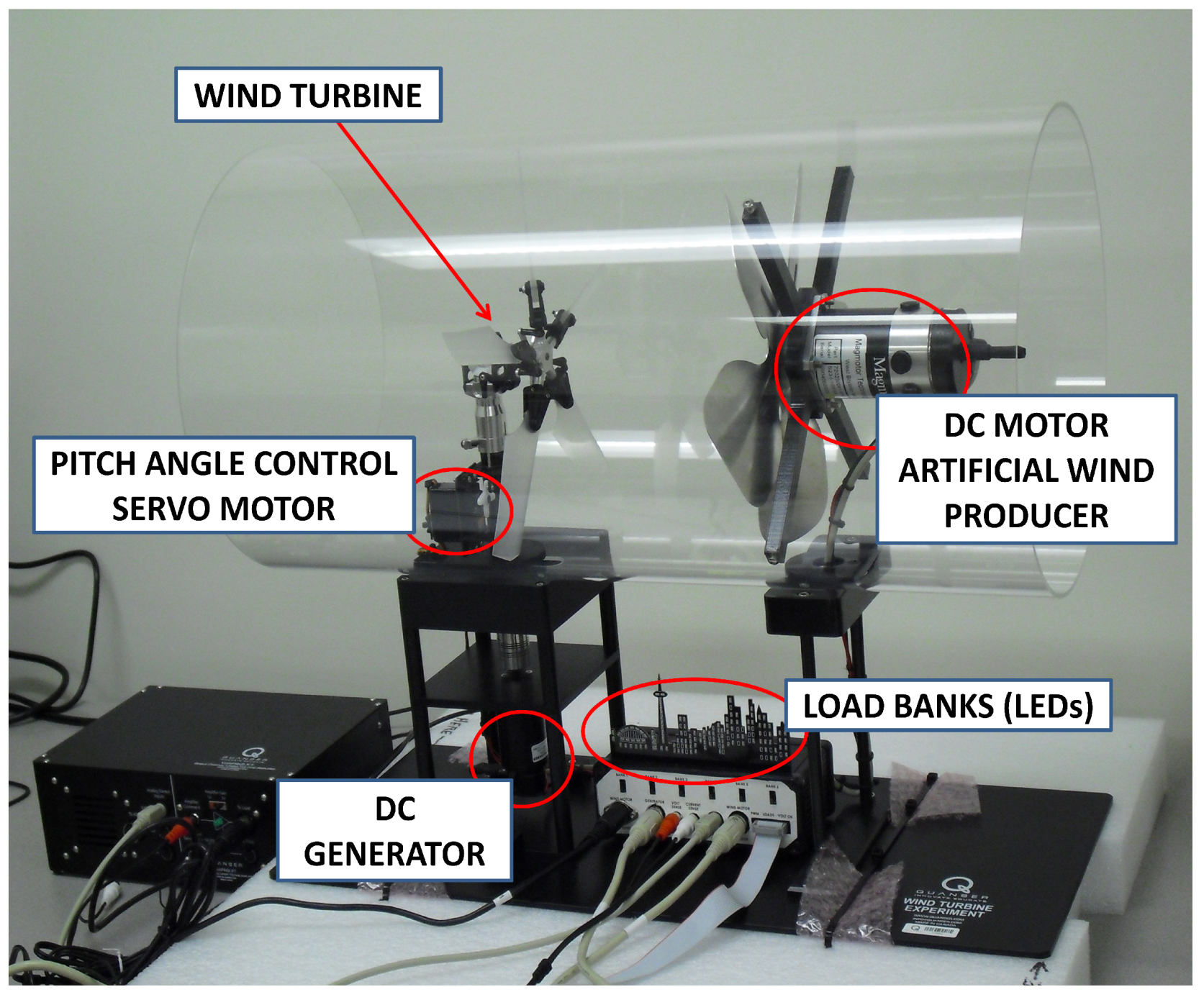
The profile of the power reference is generated based on the banks’ switches, manually turned ON by the supervisor, or the available power from wind. Therefore, the power must be regulated to track the power reference. In the experimental wind turbine, used in this work, adjustment of the pitch angle of the blades is the only way to regulate the power required for each bank or a combination of banks, and is done by the pitch servo-motor as shown in
Figure 1.
In a basic control strategy, the controlled power is compared with its reference and the error signal is sent to a PI controller to produce the optimum pitch angle
where,
βopt is the optimum pitch angle,
KP and
KI are the proportional and integral gains of the controller, respectively.
Using such a controller, the pitch angle is continuously changing, which can damage the pitch actuator, as it is in high activity. Moreover the pitch actuators have the limitation of influencing the power regulation performance of the wind turbine [
20]. In this work, a control strategy is proposed to maintain the pitch angle at a constant during steady state operation in order to reduce the activity of the pitch actuator.
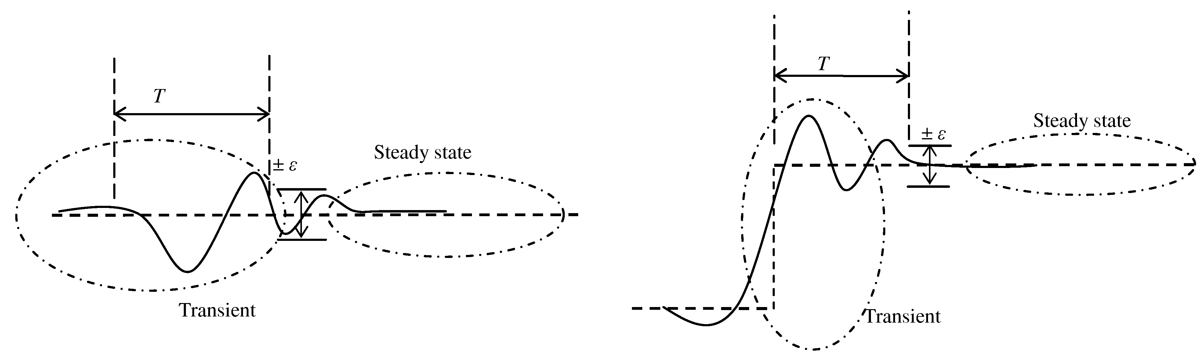
The power management system is developed for step changes in the profile of the power reference based on banks’ switching states and the available power. Therefore, the operation of the system is based on the power error compared to the error-tolerance ε. If the power error is outside the error band ± ε, the operation is considered transient, and when it is inside ± ε, it is considered steady state. Following the behavior of the generated power, two cases of operation can be observed:
(1) A change between two steps, as shown in
Figure 4, due to a change in the power demand from the supervisor or the available power from wind.
(2) A change in the power while the reference is constant, as shown in
Figure 4, due to disturbance, fluctuation and the undesirable behavior of the system.
Figure 4.
Power reference profile and generated power.
Figure 4.
Power reference profile and generated power.
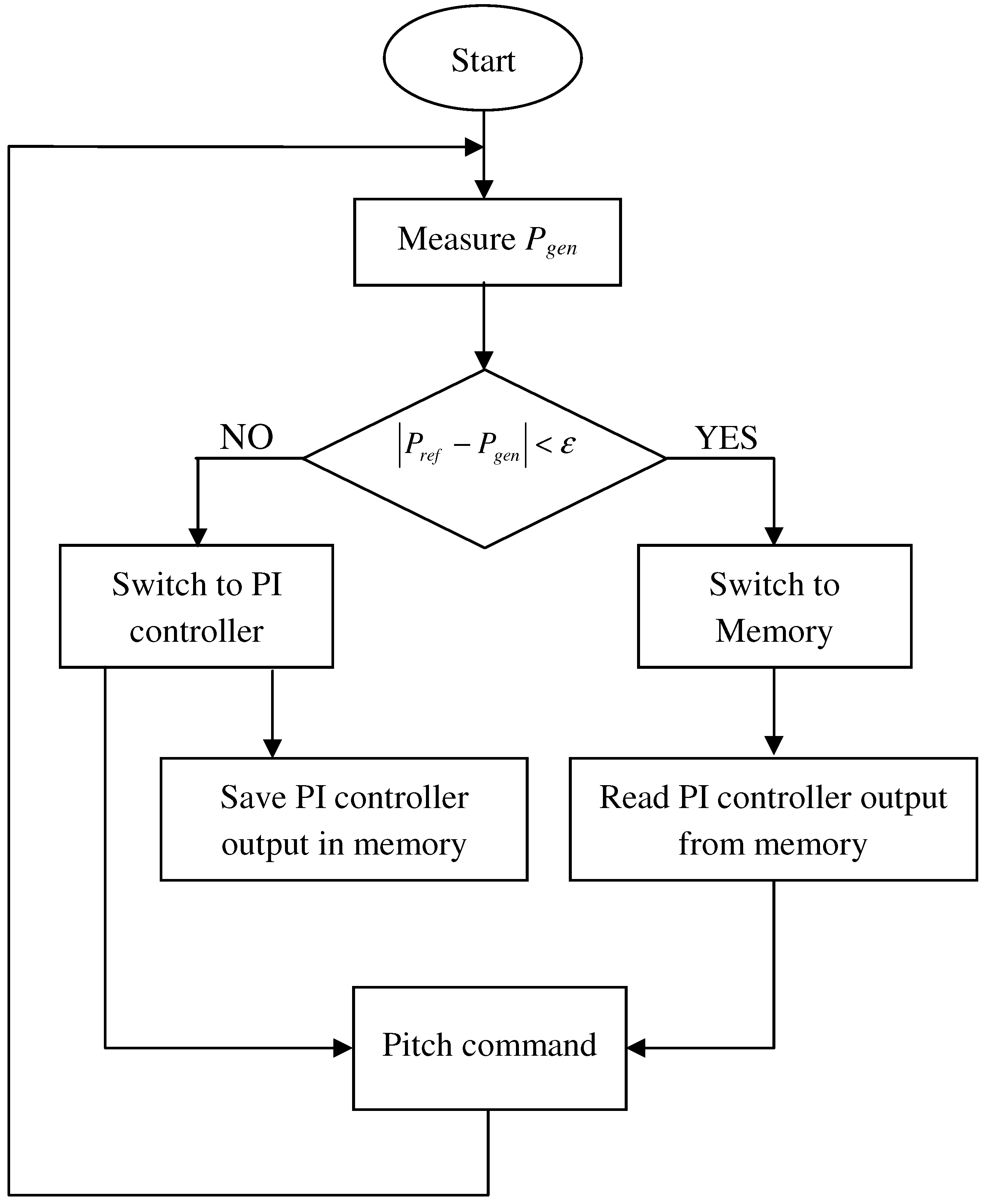
The modified pitch angle controller is based on the variation of the power error. If the power error is outside the error band ±
ε, a PI controller is applied to have the turbine track the power reference provided by the supervisor. Meanwhile, the value of the optimum pitch angle is continuously saved in a memory, and when it is inside ±
ε, the last value of the optimum pitch angle from the PI controller saved in memory, is held constant and used as a reference for the pitch actuator. The proposed pitch angle controller and its flow chart are shown in
Figure 5 and
Figure 6, respectively.
Figure 5.
Proposed PI fluctuation pitch angle control strategy.
Figure 5.
Proposed PI fluctuation pitch angle control strategy.
Figure 6.
Flow chart of the PI pitch fluctuation controller.
Figure 6.
Flow chart of the PI pitch fluctuation controller.
5. Experimental Results and Discussion
Experimentation is carried out to validate the performance of the proposed power management system and the pitch angle fluctuation controller. Algorithms and I/O data acquisition are implemented in Matlab/Simulink/QUARC. QUARC generates real-time code directly from the Simulink model and runs the generated code in real-time on the Windows target—all on the same PC. The Data Acquisition Board Q2 seamlessly interfaces with Simulink using Hardware-in-the-loop (HIL) blocks provided in the QUARC Targets Library [
19].
The choice of the proportional gain KP and integral gain KI of the PI controller is determined by trial and error method, so that the controller is tuned to achieve good performance. The value of the error tolerance ε is 0.03 W. Theoretically, reducing the value of this parameter will improve the behavior of the controller. However, its choice depends on the performance of the PI controller in transient operation. The wind speed pattern is artificially and randomly generated by the blower motor.
Initially, one bank must be turned ON in order to connect the generator to the load. Also, the banks can be manually turned ON/OFF by the supervisor before running the system. Then, the automatic switching will change the states of the banks depending on the generated power from the wind turbine and the bank’s priority.
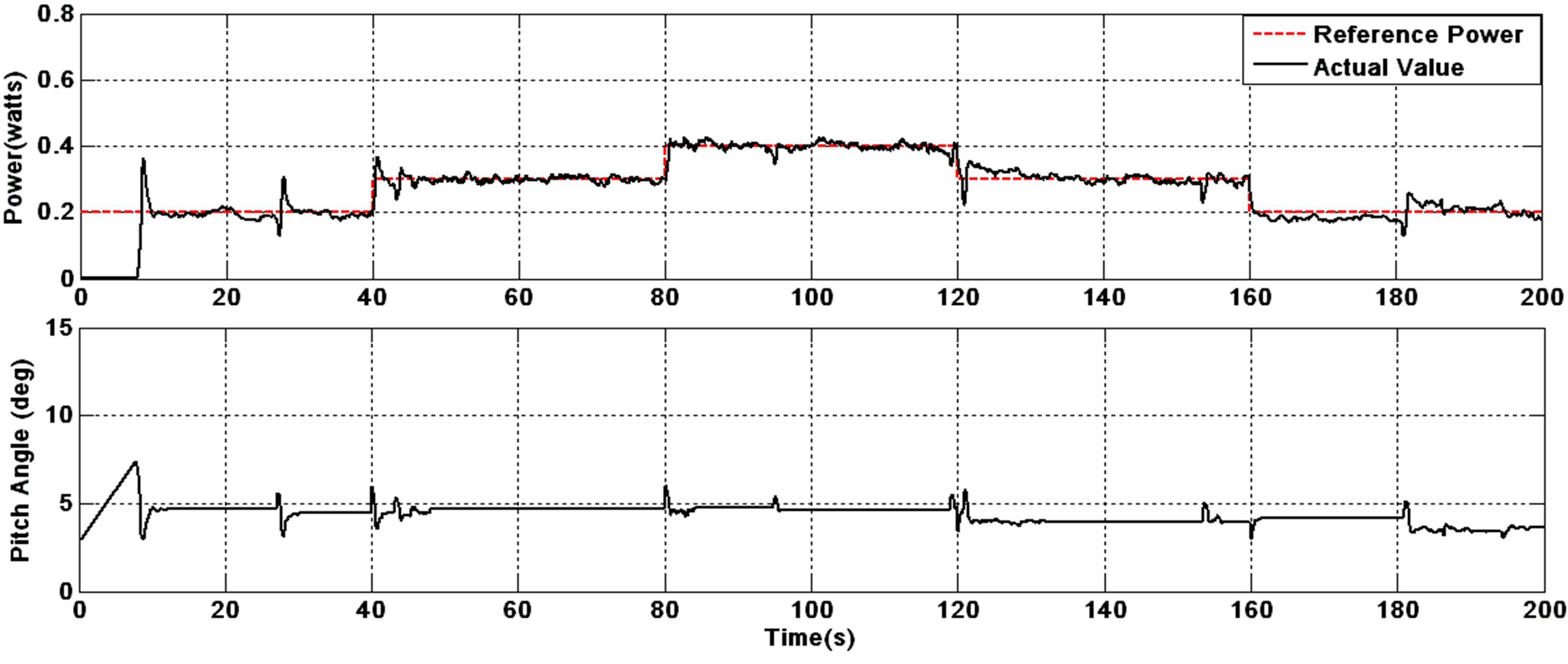
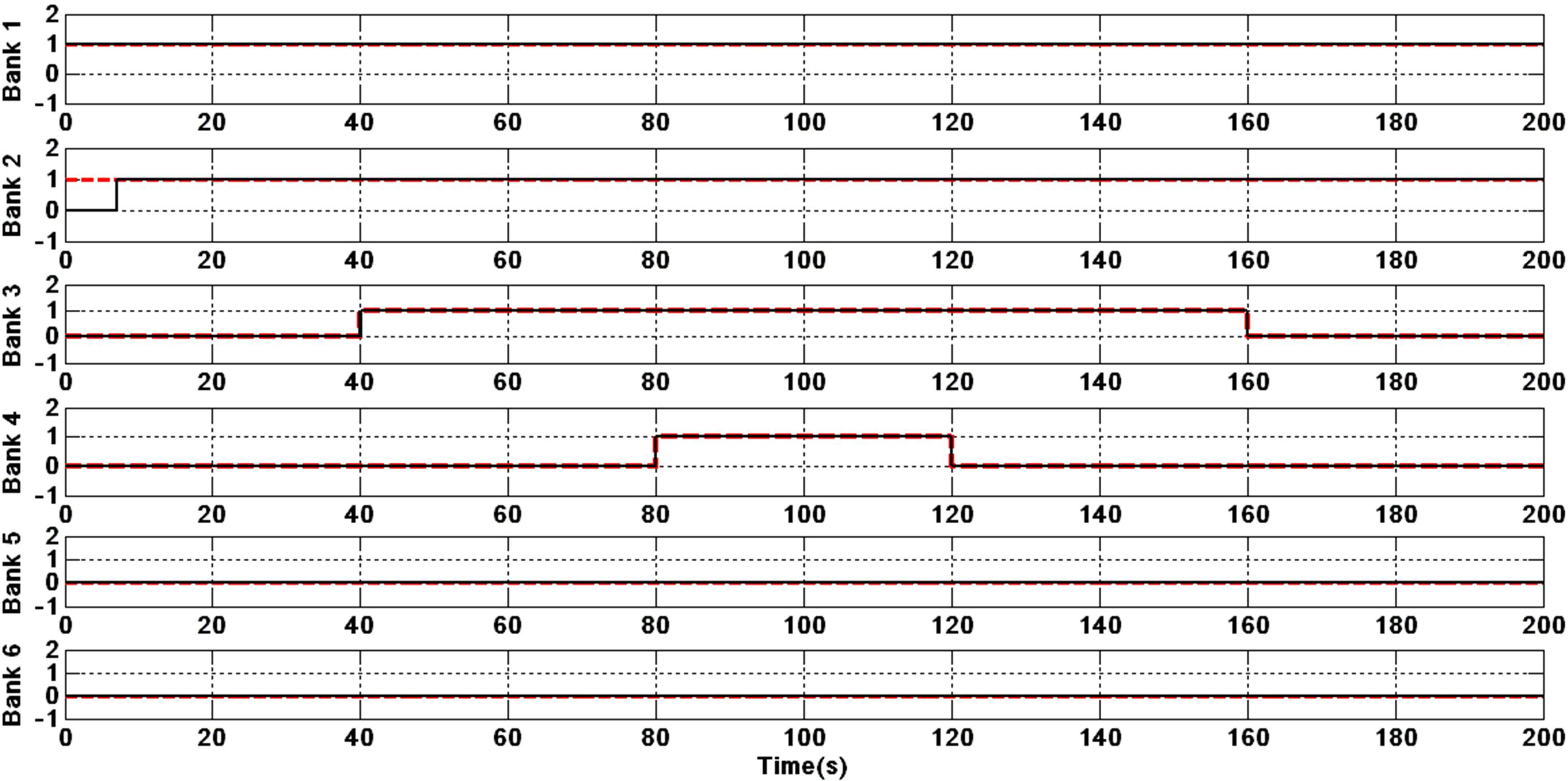
The power reference is generated based on the state of the bank’s switches, manually chosen by the supervisor and the available power from wind. The pitch angle controller adjusts the pitch angle in order for the generated power to track the reference one as shown in
Figure 7. The banks are automatically switched ON/OFF, based on the Boolean expressions in (3) of the automatic switching system, as shown in
Figure 8, where 1 ≡ ON and 0 ≡ OFF. The red dashed line represents the banks’ switching states following the power reference, and the black line represents the automatic switching based on the actual power. It can be observed that the wind turbine starts to provide power after 8 s, due to its inertia, and the bank 2, turned ON by the supervisor, will automatically turn OFF, as the generated power did not reach the power reference before 8 s. In this application, where only four banks are used, the performances of the automatic switching system and the power tracking are good. However, the pitch angle is continuously changing and fluctuating around a constant value due to the power error, as shown in
Figure 7.
Figure 7.
Generated power, reference power under PI pitch angle controller.
Figure 7.
Generated power, reference power under PI pitch angle controller.
Figure 8.
Automatic switching of the banks for the power reference of four banks (PI pitch angle controller).
Figure 8.
Automatic switching of the banks for the power reference of four banks (PI pitch angle controller).
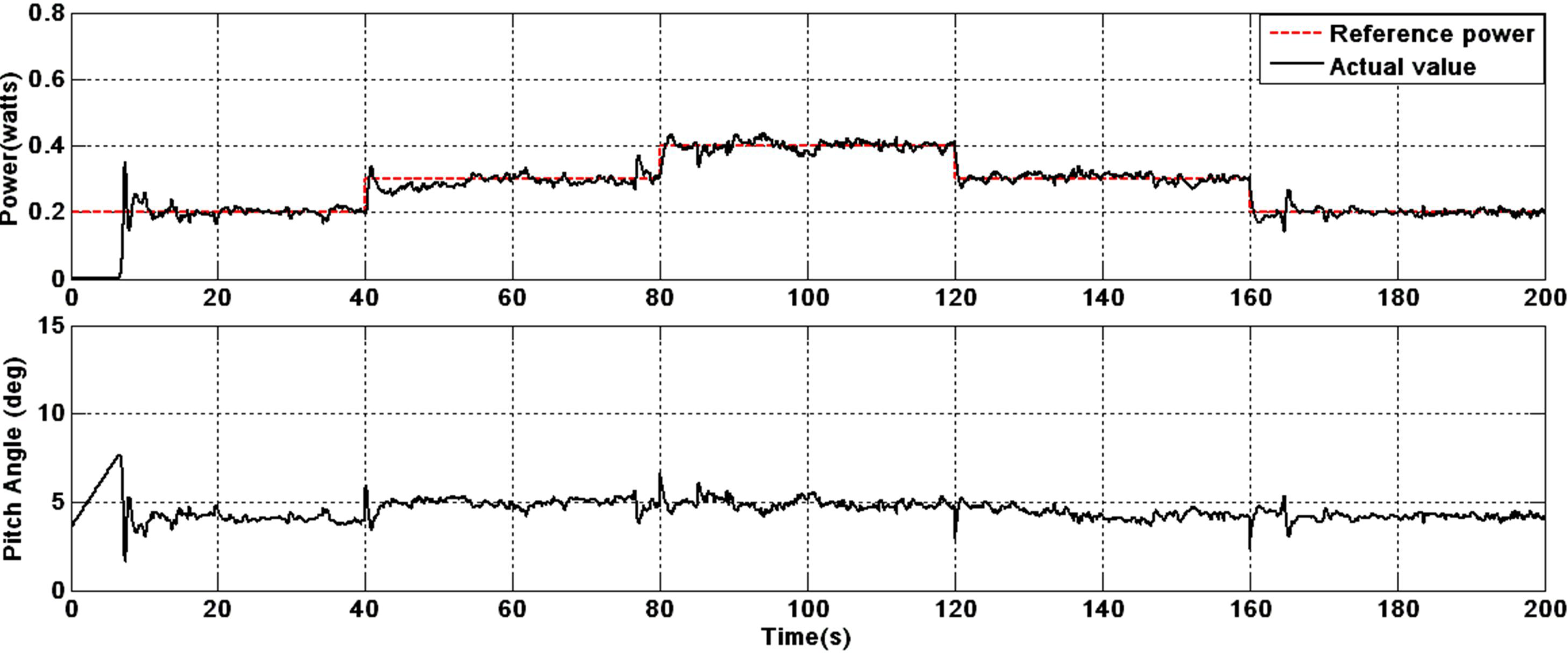
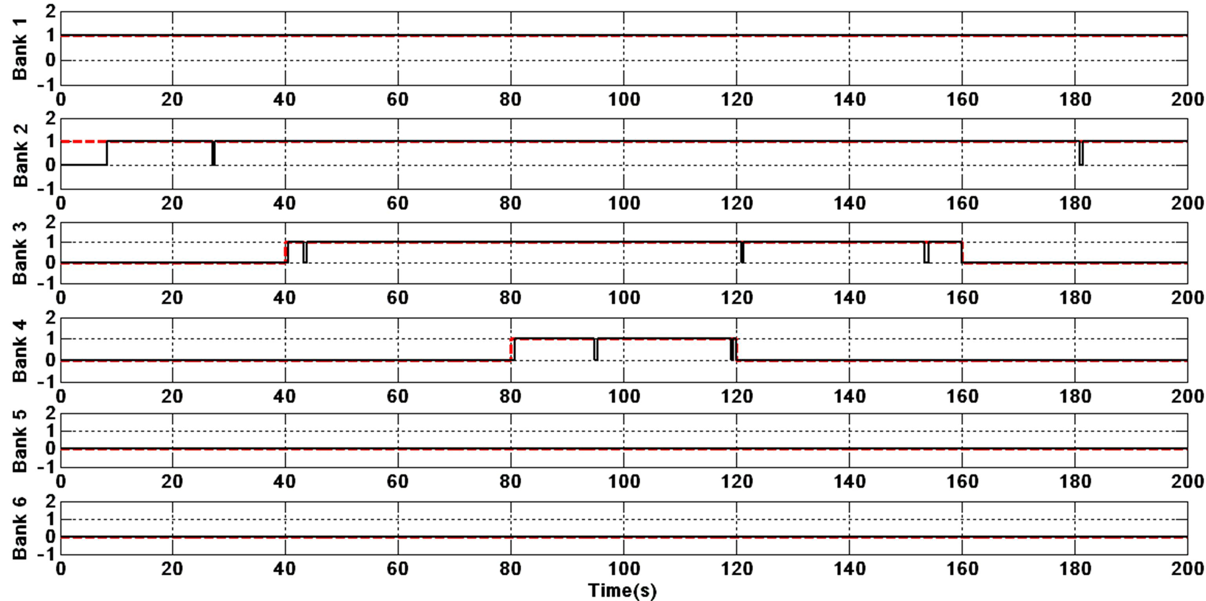
The result of the modified PI pitch angle controller for the same application is shown in
Figure 9, where the pitch angle is held constant during the power step, which reduces the activity of the pitch actuator. Less fluctuation in the power is observed during steady state operation compared to the result of the standard PI controller, which provides a consistent brilliance of the lights. However, some side effects occur in the automatic switching (
Figure 10), as banks 2, 3 and 4 turn OFF during a short time of about 1~2 s, but not seen by the eye, due to undesirable changes in the power out of the error band and wind speed variation.
Figure 9.
Generated power, reference power under modified PI pitch angle controller.
Figure 9.
Generated power, reference power under modified PI pitch angle controller.
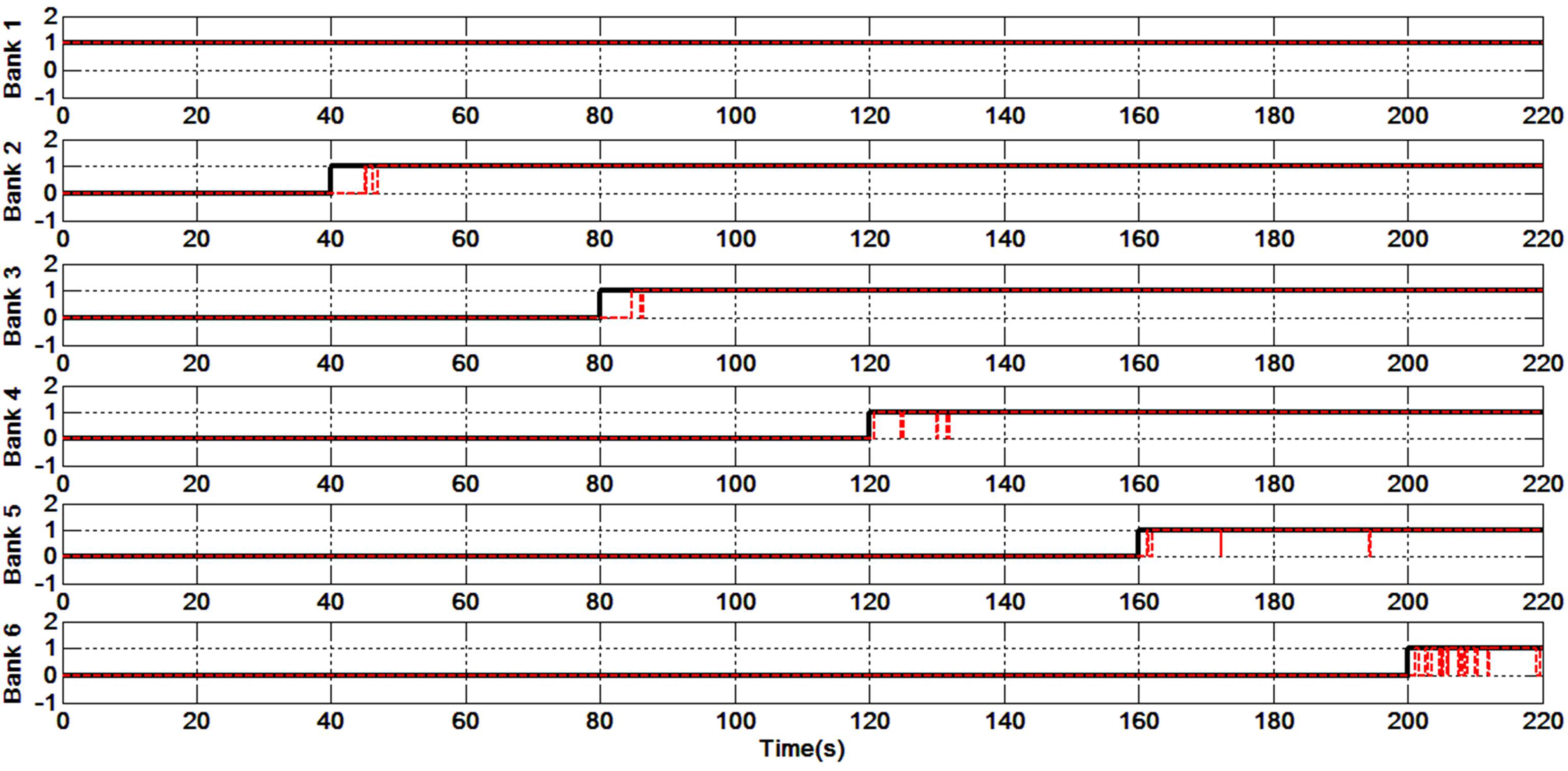
Figure 10.
Automatic switching of the banks for the power reference of four banks (modified PI pitch angle controller).
Figure 10.
Automatic switching of the banks for the power reference of four banks (modified PI pitch angle controller).
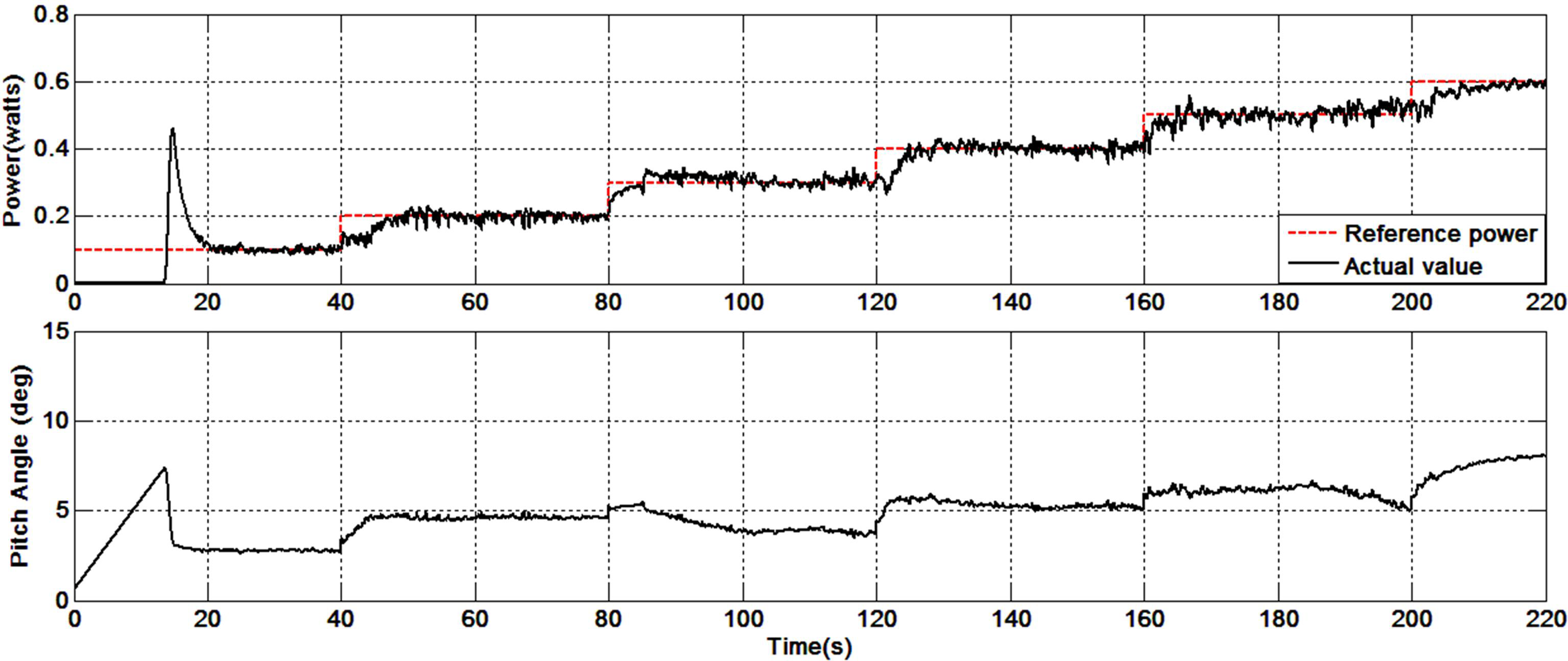
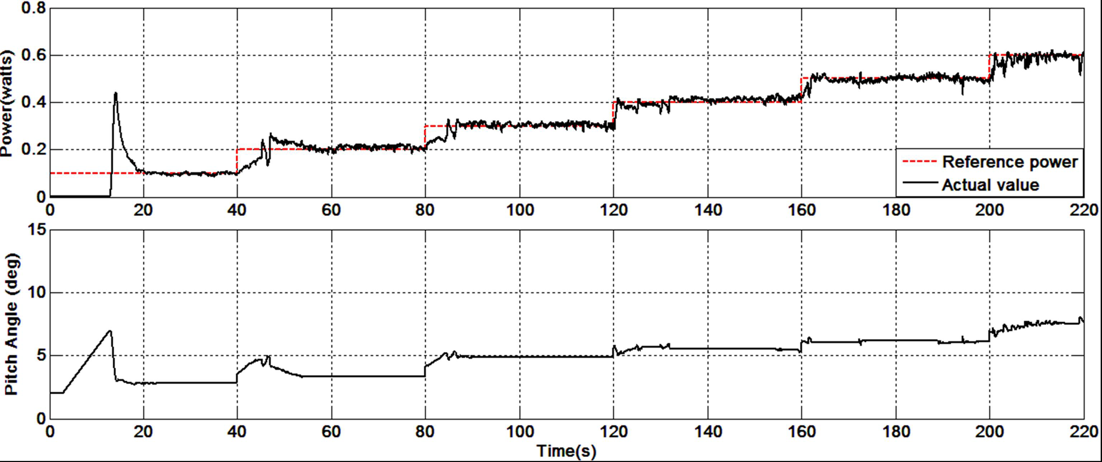
In
Figure 11, a new profile for the power reference, including the six banks, is provided to check the effectiveness of the proposed system for another scenario. It is observed that the power tracking is still good under the PI pitch angle controller. Due to the transition from one step to another, the power is insufficient to turn ON the following bank, which is noticeable in banks 4, 5 and 6 of
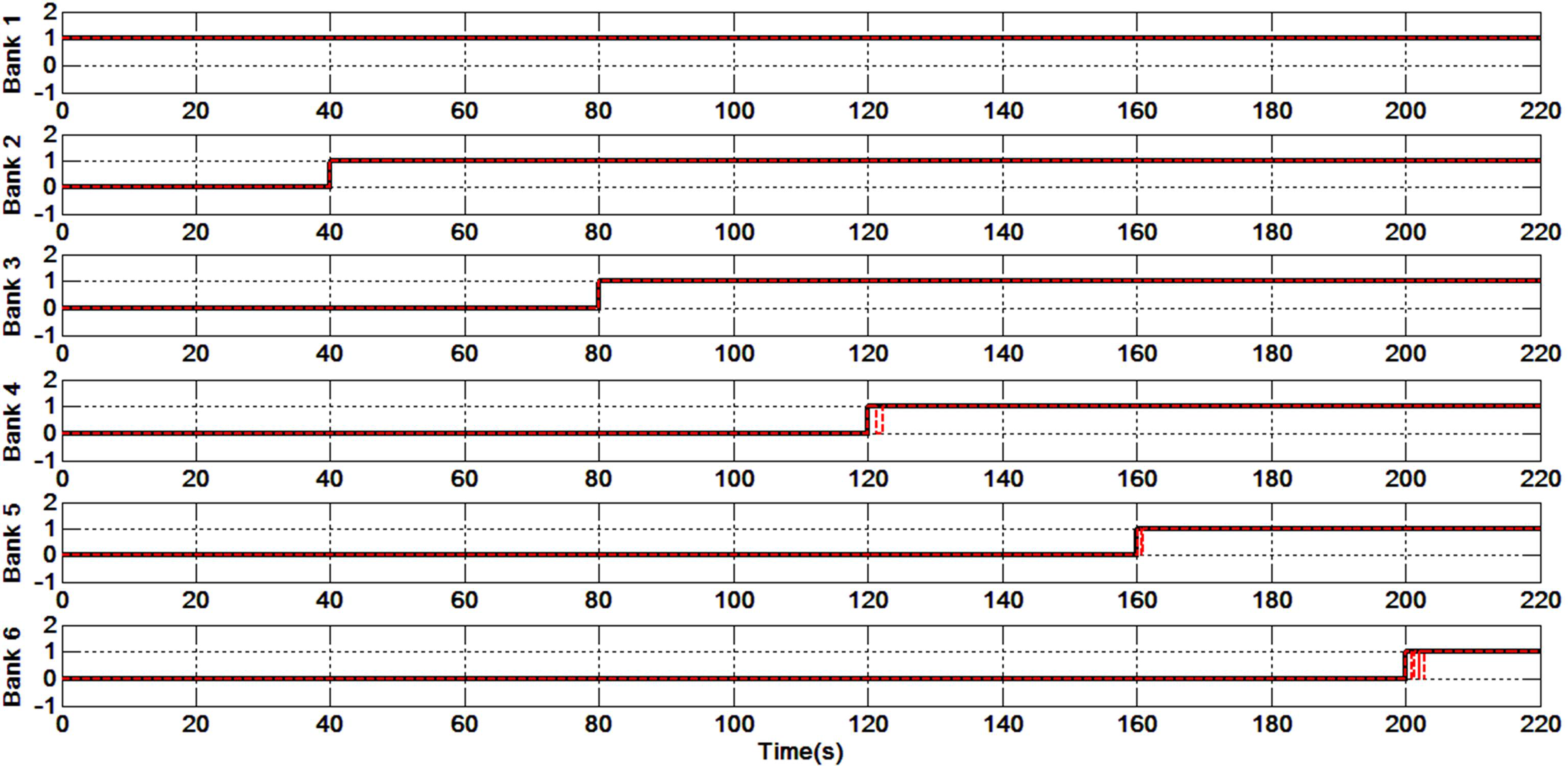
Figure 12. In
Figure 13, the power is smooth, compared to the result in
Figure 11, due to the constant pitch angle of the modified PI controller. However, with the implementation of the modified PI controller, the occurrence of multiple switching ON/OFF in banks 2, 3, 4 and 5, and more noticeable in bank 6 between 200 and 220 s in
Figure 14, is attributed to insufficient power generation due to the switching between the PI controller and the memory, and low wind speed. But still, the controller operates to find an optimum pitch angle leading to mild variations in pitch angle. It can be observed that the overall performance of the modified pitch angle controller is good, as the main purpose of this controller is to reduce the activity of the pitch actuator.
Figure 11.
Generated power and pitch angle under PI fluctuation controller.
Figure 11.
Generated power and pitch angle under PI fluctuation controller.
Figure 12.
Generated power and pitch angle under PI fluctuation controller.
Figure 12.
Generated power and pitch angle under PI fluctuation controller.
Figure 13.
Generated power and pitch angle under PI fluctuation controller.
Figure 13.
Generated power and pitch angle under PI fluctuation controller.
Figure 14.
Generated power and pitch angle under PI fluctuation controller.
Figure 14.
Generated power and pitch angle under PI fluctuation controller.

 ,
, 


