Article

Sound Absorption and Diffusion by 2D Arrays of Helmholtz Resonators

by
Iván Herrero-Durá
1,*,
Alejandro Cebrecos
2,
Rubén Picó
1,
Vicente Romero-García
3,
Luis Miguel García-Raffi
4 and
Víctor José Sánchez-Morcillo
1
1
Instituto de Investigación para la Gestión Integrada de Zonas Costeras, Universitat Politècnica de València, Carrer del Paranimf 1, 46730 Gandia, València, Spain
2
Instituto de Instrumentación para Imagen Molecular (i3M), Consejo Superior de Investigaciones Científicas, Universitat Politècnica de València, Camí de Vera s/n, 46022 València, Spain
3
Laboratoire d’Acoustique de l’Université du Mans, LAUM UMR CNRS 6613, Av. Olivier Messiaen, 72085 Le Mans, France
4
Instituto Universitario de Matemática Pura y Aplicada, Universitat Politècnica de València, Camí de Vera s/n, 46022 València, Spain
*
Author to whom correspondence should be addressed.
Appl. Sci. 2020, 10(5), 1690; https://doi.org/10.3390/app10051690
Submission received: 24 January 2020 / Revised: 20 February 2020 / Accepted: 24 February 2020 / Published: 2 March 2020
(This article belongs to the Special Issue Recent Advances in Phononic Crystals and Metamaterials)

Abstract

:
We report a theoretical and experimental study of an array of Helmholtz resonators optimized to achieve both efficient sound absorption and diffusion. The analysis starts with a simplified 1D model where the plane wave approximation is used to design an array of resonators showing perfect absorption for a targeted range of frequencies. The absorption is optimized by tuning the geometry of the resonators, i.e., by tuning the viscothermal losses of each element. Experiments with the 1D array were performed in an impedance tube. The designed system is extended to 2D by periodically replicating the 1D array. The 2D system has been numerically modeled and experimentally tested in an anechoic chamber. It preserves the absorption properties of the 1D system and introduces efficient diffusion at higher frequencies due to the joint effect of resonances and multiple scattering inside the discrete 2D structure. The combined effect of sound absorption at low frequencies and sound diffusion at higher frequencies, may play a relevant role in the design of noise reduction systems for different applications.

1. Introduction

Periodic arrays of solid scatterers embedded in a solid host, known as phononic crystals, have been exploited in the last decades for acoustic wave control, giving rise to several applications ranging from the radiofrequency regime to seismic waves [1,2]. These systems have a particular dispersion relation with the presence of band gaps [3]. Recently, with the advent of 3D printing, more complex and efficient designs are allowed [4,5,6,7]. In the particular case of rigid scatterers embedded in a fluid host, the system is known as sonic crystal because they are particularly suited for sound waves [8]. Characterization of their dispersion properties has been performed using different methods, for both ideal, i.e., infinite structures [3,9] and realistic, i.e., finite ones [10], see reference [11] for a review on band-structure calculation methods. Combining the dispersion and the bandgaps, perhaps the most developed application of sonic crystals is design of acoustic barriers for the sound mitigation of traffic noise [12,13].
Recently, a proof of concept for ultrasonic waves in water has shown that the diffusive properties of sonic crystals can be used to efficiently spread the acoustic waves when used as a cover of a cavity [14]. This system has been scaled in order to evaluate these wave diffusion properties in the case of the noise produced during the launch of a rocket. In this situation the cavity covered by the sonic crystal plays the role of the channel for exhaust gases. The results show a sound pressure level reduction in the area where the rocket is located close to 2 dB in a frequency band covering two octaves (equivalent to a decrease of 37% of the acoustic energy). Moreover, one of the main interests of using sonic crystals in this situation is that they present low flow resistivity [15] allowing the flow of both air and water through the structure. Therefore, a noise reduction solution based on sonic crystals can be added to the usual mitigation methods used during the launch of a rocket consisting in the injection of a hot supersonic pressurized water flow all around the pad [16], producing a level reduction of 3–5 dB.
The band gap in sonic crystals as well as their strong dispersion properties appear around the Bragg frequency, which is inversely proportional to the distance between the rigid scatterers in the array [8]. Therefore, if low frequency sound must be mitigated, then bulky structures are needed. In order to avoid this problem, resonant inclusions have been proposed as building blocks of such periodic arrays giving rise to the well known locally resonant materials or metamaterials [17,18]. Due to the resonance effect, new hybridized band gaps appear close to the resonance frequency of the local resonators, which can be tuned at much lower frequencies than the Bragg frequency. Some works have shown the filtering effect of such kind of locally resonant systems as well as the ultra-band gap created once the resonance of the resonant building block and the Bragg frequency are tuned [19,20,21]. Ultra-thin meta-diffusers have also been designed showing very good performance at low frequencies [22,23]. Locally resonant materials have been also used for the mitigation of sound for traffic and railway noise showing their efficiency at low frequencies [15,24,25,26,27,28,29,30,31,32].
In addition to the effects of periodicity and local resonances, the presence of viscothermal losses in a realistic system must be taken into account [33,34]. Viscothermal losses limit the strong dispersive effects in sonic crystals [35] and in acoustic metamaterials [21]. However, recently the presence of losses has been exploited to design perfect acoustic absorbers in reflection [36,37,38] and in transmission problems [39,40]. The local resonators in the acoustic metamaterials are open, meaning that they radiate energy to the host medium, and lossy, as they present viscothermal dissipation [41]. If the energy leakage of the resonators is balanced by the inherent viscothermal losses, the energy is trapped inside the resonator, dissipated in heat energy, and maximal absorption can be obtained [36]. This balance of energy leakage and losses is known as the critical coupling condition and, in the particular case of the reflection problem, corresponds to an impedance matching of the resonator with the surrounding medium.
In this work we design 2D arrays of Helmholtz resonators with optimized absorption properties at low frequencies giving rise to an improved sound diffusion in the audible regime. These two mechanisms (absorption and dispersion) could be combined to improve the previous results presented in reference [14] where only the diffusion is playing a role in the sound mitigation process. We start the analysis with a simplified 1D model where the plane wave approximation is used to design an array of Helmholtz resonators that present perfect absorption for a targeted range of frequencies. The system is optimized by tuning the geometry of the Helmholtz resonators, i.e., by tuning the viscothermal losses of each element, and perfect sound absorption is reported analytically and experimentally. Then, the system is numerically implemented in a 2D environment in which we validate the hypothesis previously assumed in the 1D modeling to design an array of Helmholtz resonators, and we evaluate both the absorption and diffusion properties of the array. Furthermore, due to the fact that the system is discrete in 2D, it combines the diffusive properties of the array with the perfect sound absorption. These two mechanisms increase the performance of the system with respect to the one previously reported in reference [14].

2. Model

In this section we present the model used to characterize the wave propagation inside the 2D array of Helmholtz resonators. A bottom up description is followed by the representation of the model of a single 2D Helmholtz resonator. In the low frequency limit, the Helmholtz resonators can be considered as point resonators. Under such conditions, the array of resonators may be treated as a 1D system, and the transfer matrix method is used to obtain its scattering parameters. Once the 1D model is presented, we introduce the numerical modeling of the 2D system used to validate the experimental results under realistic laboratory conditions. Finally, we present the noise control parameters used to evaluate the sound reduction produced by the 2D array of Helmholtz resonators. These parameters are the Insertion Loss in Reflection and the diffusion coefficient.

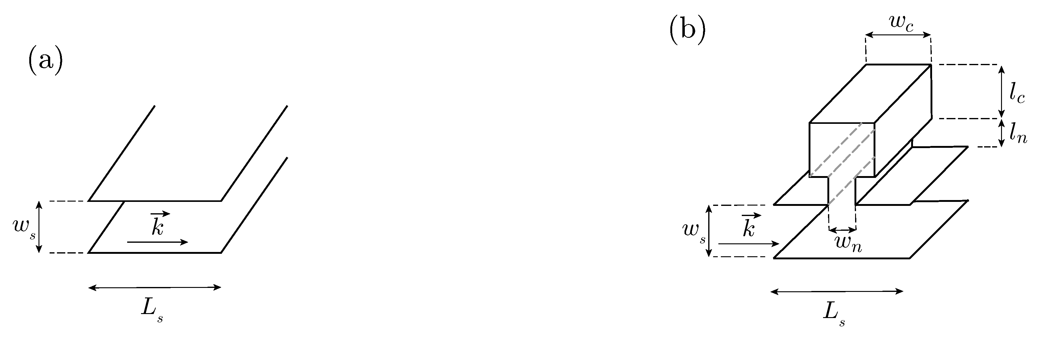
2.1. 2D Helmholtz Resonator

Plane wave propagation through a slit of width w, (see Figure 1a), taking into account viscothermal losses, can be analyzed using the frequency and complex effective physical properties of the slit, i.e., its density and bulk modulus given by Equations (1) and (2), as it was firstly introduced in reference [34]:
ρ s = ρ 0 1 tanh w 2 G ρ w 2 G ρ 1 ,
κ s = κ 0 1 + ( γ 1 ) tanh w 2 G κ w 2 G κ 1 ,
where G ρ = ı ω ρ 0 / η and G κ = ı ω Pr ρ 0 / η , and where γ is the specific heat ratio of air, P 0 is the atmospheric pressure, Pr is the Prandtl number, η the dynamic viscosity, ρ 0 the air density and κ 0 = γ P 0 the air bulk modulus. Alternatively, we can define the effective impedance Z s = ρ s κ s and wavenumber k s = ω ρ s / κ s from Equations (1) and (2).
The 2D Helmholtz resonators considered in this work are made by linking two slits with different widths as shown in Figure 1b, one playing role of the neck and the other that of the cavity. Thus, the 2D Helmholtz resonators are characterized by a neck and a cavity of width w n and w c and length l n and l c , respectively (see Figure 1b). The Helmholtz resonator is loaded in a slit (of height w). The thickness, t ( n ) , of all the walls of each Helmholtz resonator, except those corresponding to the neck, are t ( n ) = ( L s ( n ) w c ( n ) ) / 2 . Using the effective parameters for the neck and cavity, the Helmholtz resonator impedance can be written as
Z HR = l cos ( k n l n ) cos ( k c l c ) Z n k n Δ l cos ( k n l n ) sin ( k c l c ) / Z c Z n sin ( k n l n ) sin ( k c l c ) / Z c sin ( k n l n ) cos ( k c l c ) / Z n k n Δ l sin ( k n l n ) sin ( k c l c ) / Z c + cos ( k n l n ) sin ( k c l c ) / Z c ,
where k n and k c , and Z n and Z c are the effective wavenumbers and the effective characteristic impedances of the neck and cavity, respectively. The correction length used in this work, Δ l , results from the addition of two correction lengths Δ l = Δ l 1 + Δ l 2 as
Δ l 1 = 0.82 1 1.35 w n w c + 0.31 w n w c 3 w n ,
Δ l 2 = 0.82 1 0.235 w n w s 1.32 w n w s 2 + 1.54 w n w s 3 0.86 w n w s 4 w n .
The first length correction, Δ l 1 , is due to pressure radiation at the discontinuity from the neck duct to the cavity of the Helmholtz resonator [42], while the second, Δ l 2 , comes from the radiation at the discontinuity from the neck to the main waveguide [43].

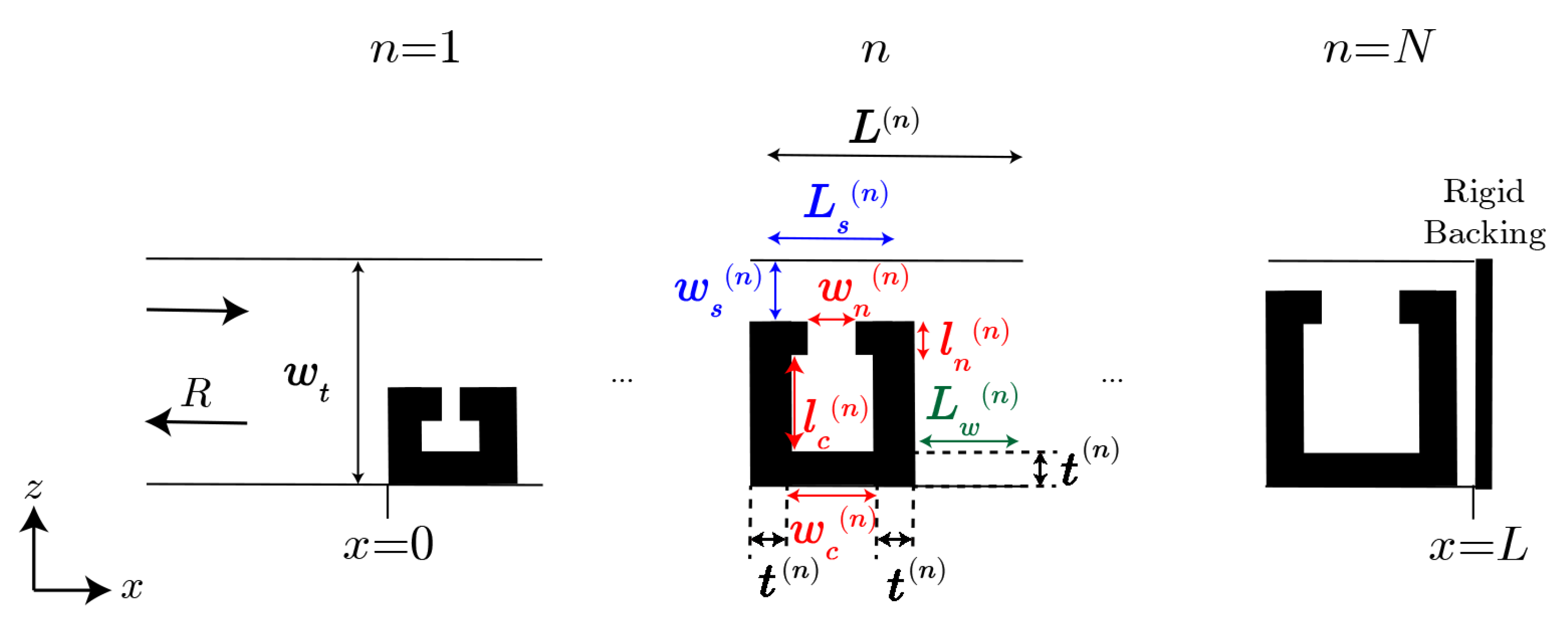
2.2. 1D Array of Helmholtz Resonators

We show here the modeling of the wave propagation along a 1D array built by assembling N building blocks, each one made of a Helmholtz resonator and a cavity, as shown in Figure 2. The propagation of waves in this system is modeled using the Transfer Matrix Method (TMM). We consider the reciprocal system n in which only plane waves propagate. By assembling the matrices representing each building block of the array in a total transfer matrix T , the pressure, p, and flux velocity, v, at x = 0 can be expressed in terms of the pressure and velocity at x = L as
p v x = 0 = M p v x = L = M 11 M 12 M 21 M 22 p v x = L .
As illustrated in Figure 2, the complete system can be represented by N individual building blocks made of a Helmholtz resonator loaded in a slit of length L s ( n ) and a width w s ( n ) , a cavity with a length L w ( n ) , everything embedded in a main tube of width w t . In this paper we use upper-case letters for the geometric parameters outside the resonators and lower-case for those of the Helmholtz resonators. Sub-indexes represent slit (s), neck (n) cavity (c) or waveguide (w). The total length of the system can be obtained as follows:
L = n = 1 N L ( n ) = n = 1 N ( L s ( n ) + L w ( n ) )
The transfer matrix of the n-th building block, M b ( n ) may be written as
M b ( n ) = M Δ l s l i t ( n ) M s ( n ) M H R ( n ) M s ( n ) M Δ l s l i t ( n ) M w ( n ) ,
where, M Δ l s l i t ( n ) represents the transfer matrix corresponding to the correction due to the change of section between the main tube and the Helmholtz resonator (if there is not change of section, this matrix is the identity matrix), M s ( n ) is the transfer matrix representing the propagation of waves through the slit along a distance L s ( n ) 2 , M H R ( n ) represents the transfer matrix of the Helmholtz resonators, and M w ( n ) is the transfer matrix of the propagation along the cavity. These matrices are defined as follows:
  • The transfer matrix for each step in the slit of the n-th building block, M s ( n ) , reads as
    M s ( n ) = cos k s ( n ) L s ( n ) 2 ι Z s sin k s ( n ) L s ( n ) 2 ι Z s sin k s ( n ) L s ( n ) 2 cos k s ( n ) L s ( n ) 2 ,
    where k s , Z s are the wavenumber and the impedance in the slit. As it was previously mentioned, the term Ms is applied along a distance L s ( n ) 2 . Thus, this term must be considered twice in the transfer matrix of the building block (before and after the one corresponding to the Helmholtz resonator).
  • The transfer matrix for each resonator, M H R ( n ) , is defined as
    M H R ( n ) = 1 0 1 Z H R ( n ) 1 ,
    being Z H R the acoustic impedance of the Helmholtz resonator. Notice that this definition is valid when λ w n , where the Helmholtz resonators can be considered as point resonators.
  • The transfer matrix for the radiation correction of the slit to the free space, M Δ l s l i t ( n ) , can be defined as
    M Δ l s l i t ( n ) = 1 Z Δ l s l i t ( n ) 0 1 ,
    with Z Δ l s l i t ( n ) = ι ω Δ l s l i t ( n ) ρ 0 / ϕ t ( n ) S 0 the characteristic radiation impedance, where ω is the angular frequency, ϕ t ( n ) = w s ( n ) / w t is the total porosity and S 0 ( n ) = w t L s ( n ) . Δ s l i t = Δ l 1 + Δ l 2 is the length correction, where Δ l 1 is the length correction given by the pressure radiation at the discontinuity from the neck duct to the cavity of the Helmholtz resonator, and Δ l 2 comes from the radiation at the discontinuity from the neck to the principal waveguide (see reference [38]) given by Equation (4) and Equation (5). It is important to note that, due to the symmetry of each resonator, the radiation correction of the slit to the free space must be applied at both sides of the structure.
  • The transfer matrix for the air cavity placed behind the Helmholtz resonator, M w ( n ) , is defined in the following form
    M w ( n ) = cos k 0 L w ( n ) ι Z 0 sin k 0 L w ( n ) ι Z 0 sin k 0 L w ( n ) cos k 0 L w ( n ) ,
    where k 0 and Z 0 are the wavenumber and the acoustic impedance of the air. In this part of the system we consider that the width of the tube is large enough to neglect the effect of viscothermal losses.
The total transfer matrix of the system can be built by multiplying the transfer matrix corresponding to the different building blocks as follows:
M = n = 1 N M b ( n ) = n = 1 N M Δ s l i t ( n ) M s ( n ) M H R ( n ) M s ( n ) M Δ s l i t ( n ) M w ( n ) .
In our case we are considering the reflection problem and, thus, at x = L we consider a Neumann boundary condition, i.e., an acoustically rigid wall by means of assuming v ( x = L ) = 0 . It is worth noting here that the total length of the system is given by L = n = 1 N L n = n = 1 N L s n + L w n . By considering this, we can obtain the reflection coefficient by using the following expression,
R = M 11 Z 0 M 21 M 11 + Z 0 M 21 .
Thus, the absorption coefficient is directly calculated as follows,
α = 1 | R | 2 .

2.3. 2D Finite Array of Helmholtz Resonators

The 1D array considered in Section 2.2 can be periodically replicated along the z-axis with a periodicity w t , therefore creating a 2D finite array of Helmholtz resonators. The geometries of the Helmholtz resonators used in the 2D case are identical to the ones used in the 1D system since the sound absorption should cover the same frequency range. The acoustic response of this structure will be studied numerically using the Finite Element Method (FEM). The array is excited with a plane wave from the left size, analogously as it was done in the 1D case. The whole numerical domain will be surrounded by Perfectly Matched Layers in order to avoid spurious reflections and numerically replicate the Sommerfeld radiation conditions. The neck and the cavities of the Helmholtz resonators as well as the slits will be modeled as equivalent fluids with the corresponding complex and frequency dependent density and bulk modulus, as described in Section 2.1, in order to consider the effect of viscothermal losses. This numerical model is used later to validate the results from the experimental measurements in the anechoic chamber and also to evaluate the different side effects coming from the finite size of the structure.

2.4. Noise Control Parameters

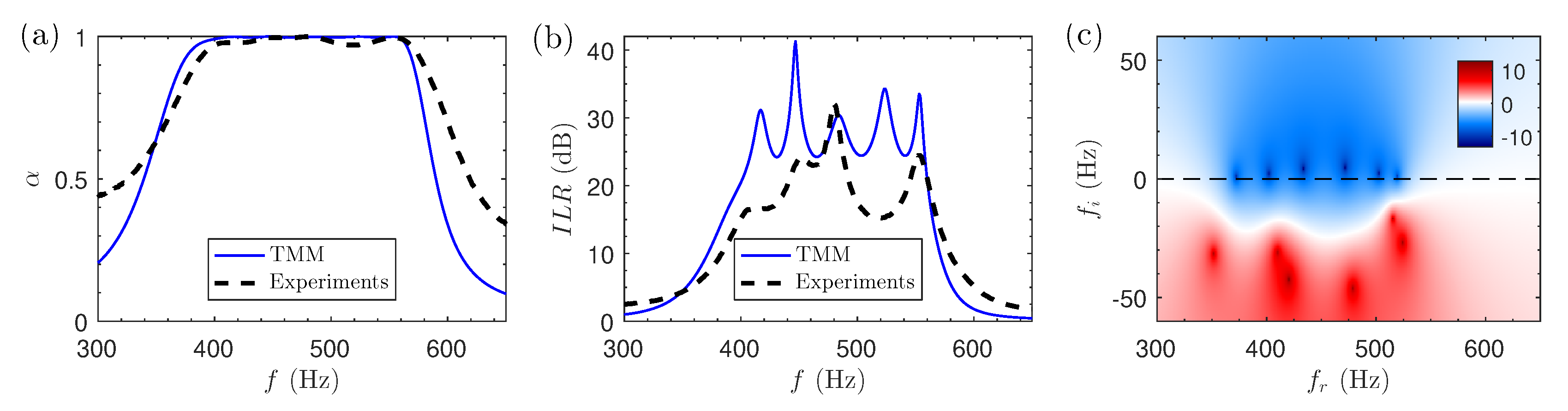
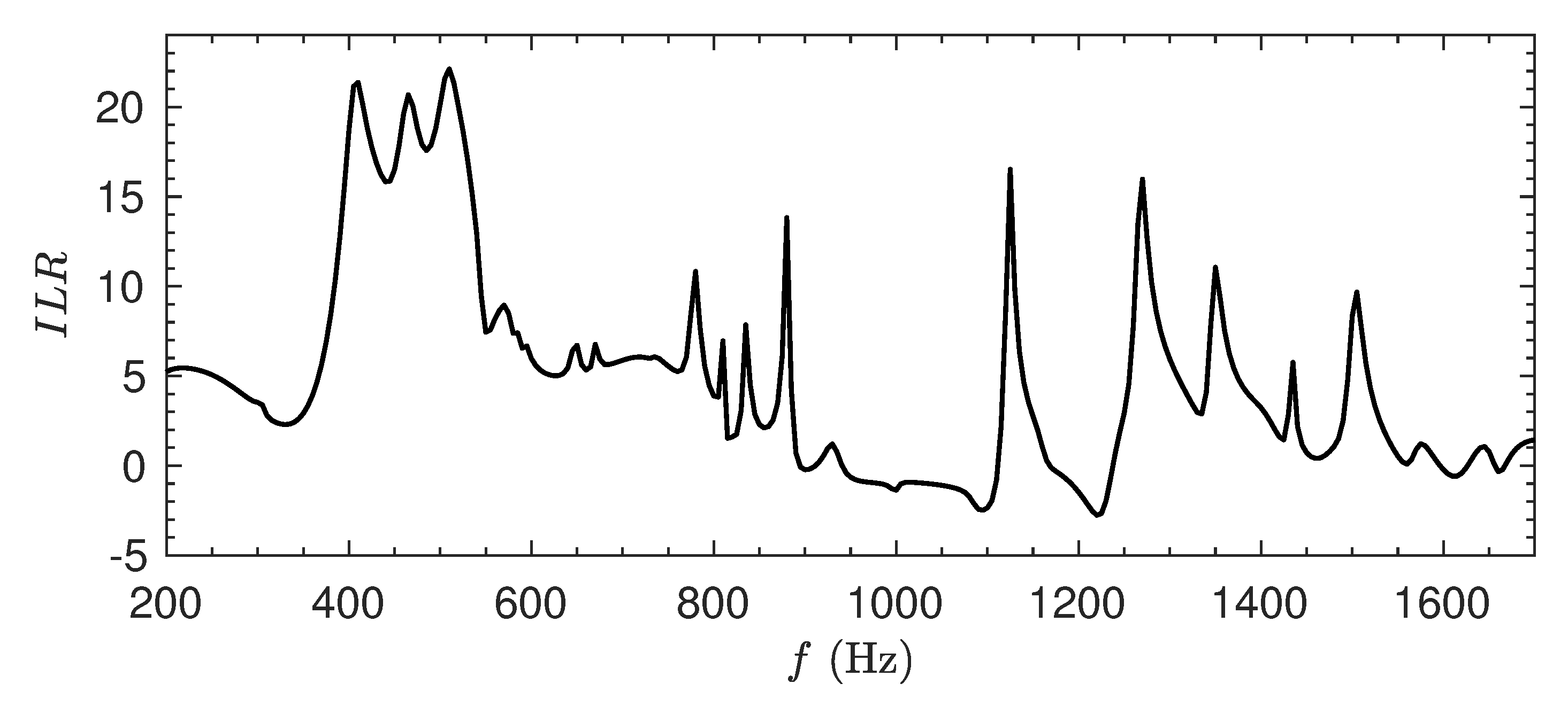
2.4.1. Insertion Loss in Reflection

The Insertion Loss (IL) is defined as the difference between sound pressure levels measured before and after a sound absorbing material is located in the path between the source and the receiver [12]. When both the source and the receiver are placed at the same side, as is our case, the concept of I L is used as in reference [14]. In this case, the original definition of I L was extended to characterize systems where only reflection and absorption (but no transmission) is allowed (Insertion Loss in Reflection, ILR).
The magnitude of ILR of a given system is obtained by determining the acoustic pressure at different positions and frequencies, p ( x , f ) . The measurement positions are located in front of the system to be studied. The IL is a relative parameter, comparing the acoustic pressure field scattered by the structure with respect to a reference case. In our study, a rigid wall is selected as a reference. Therefore, the definition of ILR reads:
I L R [ dB ] L r e f L H R = 10 log | p r e f | 2 | p H R | 2 ,
where, p r e f and p H R are the acoustic pressures measured for the reference case and for the system of Helmholtz resonators, respectively, and L r e f and L H R the sound pressure level in both cases.

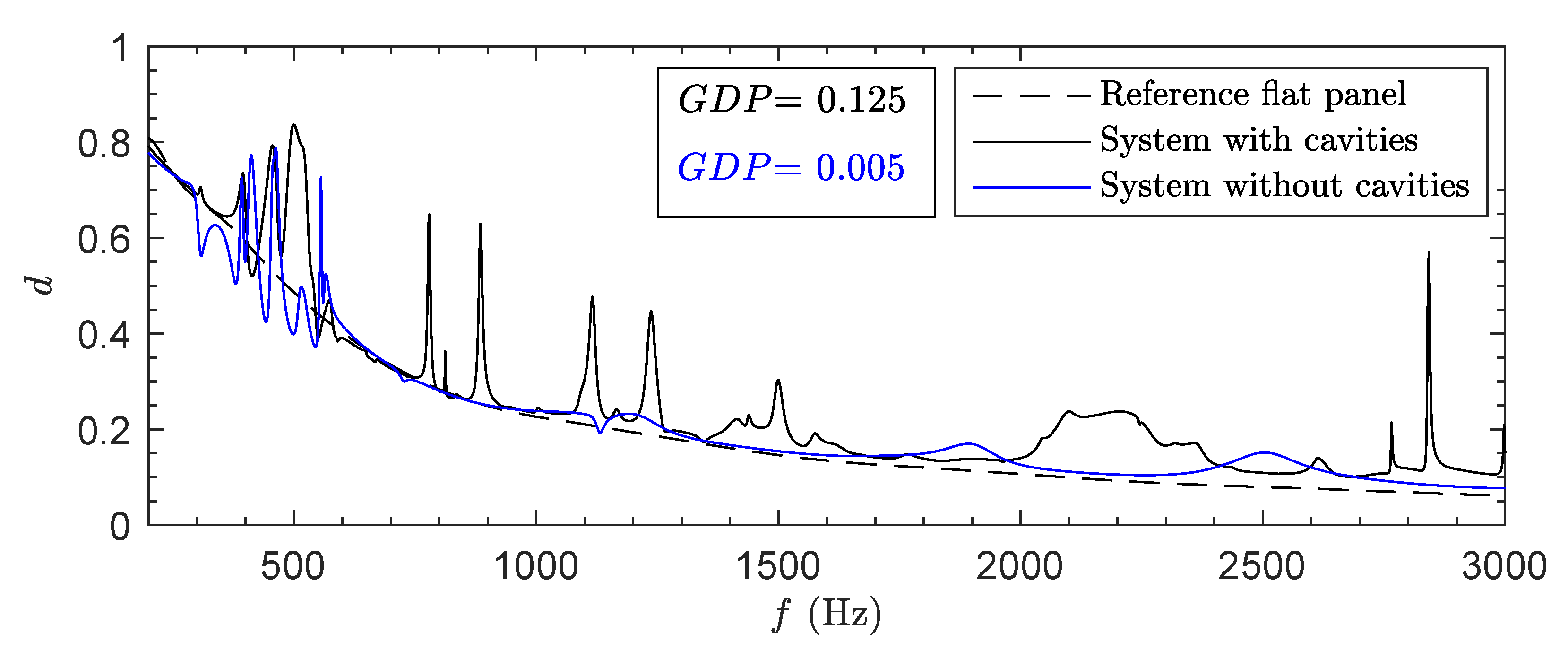
2.4.2. Diffusion Coefficient

With the presence of a rigid backing after the absorbing material, sound energy can only be absorbed, or reflected back from the surface. Reflection may be specular, by following Snell’s law, or diffuse, the wave spreading according to a given pattern. In order to estimate the diffusiveness of the field, the diffusion coefficient d is used.
The diffusion coefficient can be estimated by measuring the scattered far-field at different angles, as specified in the standard ISO 17497-2 [44]. It obeys the expression [14]
d = i = 1 n 10 S I L i / 10 2 i = 1 n 10 S I L i / 10 2 ( n 1 ) i = 1 n 10 S I L i / 10 2 ,
where S I L i is the Sound Intensity Level of the far field in the i-th measurement position, defined as S I L i = 10 log I i I 0 , n is the total number of measurement positions, I i and I 0 are the acoustic intensity in the i-th position and the reference intensity, respectively. In our study, the sound pressure has been evaluated in the far field, at 83 angular positions ranging from −90 to 90 , where 0 is the direction of normal incidence along the x direction.
A flat panel with the same dimensions as the evaluated structure is considered as the reference case. We define the global diffusion parameter ( G D P ) as
G D P = f 1 f 2 ( d d r e f ) d f f 2 f 1 ,
where, d and d r e f are the diffusion coefficients of the system under study and the reference case, respectively, and f 1 and f 2 are the minimum and maximum frequencies of the working frequency range. The parameter G D P gives an estimation of the overall diffusion properties for the range of frequencies of interest: G D P = 0 means that the evaluated system has similar diffusion properties as the reference, G D P > 0 ( G D P < 0) means that the evaluated structure presents higher (lower) diffusion coefficient in average for the evaluated range of frequencies than the reference.

3. Experimental Setups

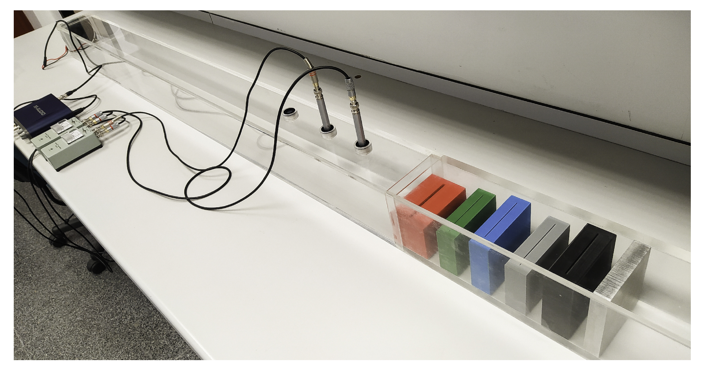
3.1. Impedance Tube: 1D System

The experimental setup used for the characterization of the reflection and absorption properties of the 1D system of Helmholtz resonators is designed following the guidelines of the Standard UNE-EN-ISO 10534-2 [45]. A picture of the experimental setup is shown in Figure 3. The impedance tube has a square shape section with side length w t = 10 cm and a total length of 1.5 m, along the propagation direction. A loudspeaker Fonestar UT-4104, controlled by a M-AUDIO FastTrack Pro sound card, was placed at one end of the tube. The system of 5 Helmholtz resonators was manufactured using in polylactic acid (PLA) using 3D printing. The printer (Anycubic i3 Mega) operates with a layer resolution of 0.05 mm, and a nozzle diameter of 0.4 mm. It was placed at the other end of the tube backed by a totally reflecting metallic block acting as a rigid end. Two B&K 4189 microphones with their respective preamplifiers (B&K 2671) are mounted on the tube walls, separated by a distance of 9 cm. The closest microphone to the sample is placed at 10 cm from the sample. The low and high cut-off frequencies are f l = 200 Hz, f h = 1700 Hz, respectively.

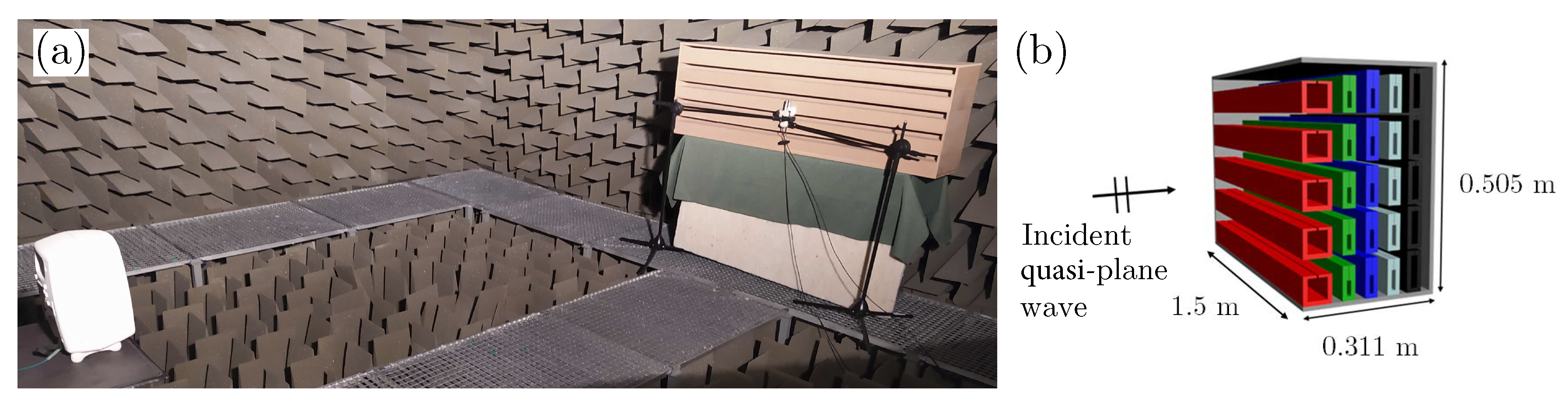
3.2. Anechoic Chamber: 2D System

The experimental configuration of the 2D array of Helmholtz resonators is characterized under realistic conditions in an anechoic chamber, as shown in Figure 4. The whole structure is surrounded by acoustically rigid wood panels at all ends except the side where the incident wave is impinging on the structure (see Figure 4). Both the Helmholtz resonators and the rigid panels are made of medium density fiber, a material that has an acoustic impedance much greater than the one of air and hence, can be considered as acoustically rigid. The procedure for the experimental characterization is based on a modified version of the Transfer Function Method (TFM), as described in references [46,47]. The loudspeaker (Genelec 8030A) is controlled by the same sound card mentioned previously and it is placed sufficiently far from the structure to ensure quasi-plane wave propagation at the frequency range of interest ( D = 3 m). Two B&K 4189 microphones with their respective preamplifiers (B&K 2671) are placed very close to the structure ( d = 1.5 cm), separated by a distance d = 2.5 cm.

4. Results

As described in Section 2.2, acoustic wave propagation along an array of Helmholtz resonators is modeled using the TMM for the 1D system. Once the targeted scattering properties of the system are obtained, i.e., maximum absorption for a given frequency range, the obtained geometry of the Helmholtz resonators is extrapolated to more realistic conditions by periodically replicating the 1D system along the z-direction creating a 2D array. This system is numerically modeled and experimentally validated in an anechoic chamber. The design of the 1D system is performed by using an optimization technique (Sequential Quadratic Programming (SQP) method) employing TMM to maximize the absorption coefficient for a range of frequencies f = [ 400 , 560 ] Hz, in which the number of resonators is fixed to N = 5 , including cavities (spaces) in between the resonators. The resulting geometry of the optimized structure is shown in Table 1, following the nomenclature introduced in Figure 2. In our case, the value of t ( n ) is 9 mm for all the Helmholtz resonators ( t ( n ) = 9   mm n).

4.1. Results for the 1D Problem: Sound Absorption and ILR

Figure 5 summarizes the theoretical and experimental results obtained using the 1D array of Helmholtz resonators in the impedance tube. We first evaluate analytically and experimentally the sound absorption coefficient along the range of frequencies of interest, as shown in Figure 5a. The results obtained from the TMM results indicate an almost perfect absorption α > 0.995 for the whole targeted frequency range, including 5 peaks with increased absorption ( α > 0.999 at peak). Experimental results agree well with theoretical ones, especially at the resonance frequencies. Small differences between the theory and the experiments could be attributed to different reasons, including insufficient accuracy in the manufacturing process, small deviations placing the Helmholtz resonators modifying the length of the cavities (spacing between resonators) or even excitation of plate modes of some of the panels forming the resonators. The corresponding ILR values emphasise the aforementioned differences between theory and experiments. However, experimental ILR results are above 15 dB at all frequencies of interest, reaching experimentally peaks up to 32 dB.
The reflection coefficient represented in the complex frequency plane is shown in Figure 5c. For a critically coupled system, where the coupling between the resonators and the propagating medium (energy leakage), and the intrinsic losses of the resonator are balanced, the zeros should be located exactly on the real frequency axis. However, for a set of N resonators, this is the case if the system is optimized to obtain perfect absorption at N discrete frequencies. In this work, the goal is to get the highest global absorption for a certain frequency range, which results in the zeros of | R | located very close, but not exactly at the real frequency axis, i.e., not all the resonances are critically coupled.

4.2. Results for the 2D Problem

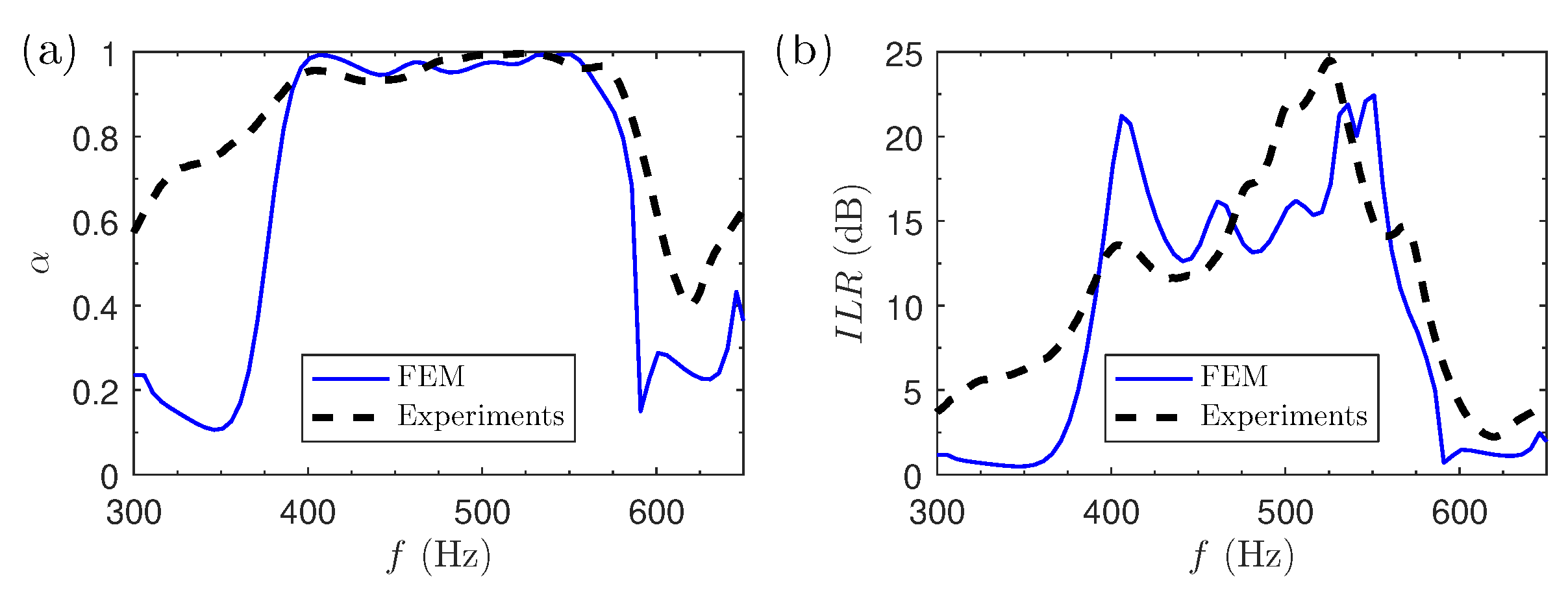
4.2.1. Sound Absorption and ILR

The absorption properties of the structure shown in Figure 4 are characterized experimentally in an anechoic chamber and are compared to numerical simulations solving a 2D model using FEM. In both cases, the method employed to measure the sound absorption coefficient consists of a modified version of the TFM, as explained in Section 2.4. Figure 6 illustrates both the sound absorption coefficient and the ILR, evaluated numerically and experimentally. The absorption coefficient from numerical simulations, as shown in Figure 6a, follows a very similar trend as in the 1D system (see Figure 5a): Almost perfect absorption for the optimized frequency range, f = [ 400 , 560 ] Hz, including 5 resonant peaks corresponding to each of the building blocks with different geometries, with absorption values α > 0.95 . Experimental results agree quite well with simulations, with a maximum absorption of α = 0.996 at f = 525 Hz and α > 0.95 for the whole frequency range except a small reduction around f = 435   Hz , where the absorption reaches its minimum, α = 0.93 . Despite these small differences and due to the similarity of the absorption values obtained in the 1D and 2D systems, we can validate the hypothesis that the use of 1D modeling to design a 2D array of Helmholtz resonators is accurate enough for the purpose of this work. The corresponding ILR values in dB, shown in Figure 6b emphasize the aforementioned differences between theory and experiments. However, experimental ILR results are above 12 dB at all frequencies of interest, reaching experimentally peaks up to 25 dB.

4.2.2. Diffusion Coefficient

In this section we evaluate the diffusion coefficient of the optimized structure. In order to highlight the role of the cavities in the structure we compare it with the diffusion coefficient of a system without cavities, also optimized for perfect absorption for the same range of frequencies. As a reference system we consider a flat rigid panel with the same dimensions as the other two structures. The diffusion coefficient and the G D P have been evaluated as explained in Section 2.4 for frequencies ranging from f 1 = 200 Hz to f 2 = 3000 Hz and for normal incidence.
Figure 7 shows the diffusion coefficients of the three evaluated structures. The flat panel presents a monotonous diffusion coefficient decreasing in frequencies, meaning that as frequency increases the scattered wave is more directional. The array without cavities is very close to that of the flat panel, except for the range of frequencies where it was optimized for perfect absorption. For the optimized array with cavities we can see that the diffusion coefficient presents several peaks due to the fact that sound penetrates in the system and combined effects of resonances and multiple scattering take place producing diffusion of sound.
In order to quantify the diffusion for the overall range of frequencies we have used the G D P (see Section 2.4). We can see that for the system without cavities, although it is optimized between 400 and 560 Hz, the G D P takes a value close to 0, meaning that the system in terms of diffusion behaves like a flat panel. However, for the system with cavities, the G D P increases up to 0.125, showing that the behavior is far from a flat panel, producing an efficient sound diffusion due to the combined effect of resonances and multiple scattering in the structure.

5. Discussion

The mitigation of sound is a scientific and technological challenge for several applications. Recently, the diffusion of sound produced by sonic crystals, as 2D periodic arrays of rigid scatterers embedded in air, has been used as a noise mitigation mechanism to reduce the sound level around an acoustic source placed in front of this periodic system [14]. These results are a proof of concept in which the main motivation is to incorporate these crystals in future launch-pad designs as a broadband noise reduction system for aerospace applications [48]. However, sonic crystals are not efficient at low frequencies and in the previous work only the diffusion was used as mitigation mechanism. In the current work, we introduce absorption at low frequencies combined with the multiple scattering processes that arises from the discreteness of the array allowing also diffusion of sound at higher frequencies.
Figure 8 shows the ILR of the designed structure in this work covering the low frequency range, in which the absorption has been optimized, and the medium/high frequencies, in which the diffusion of sound, i.e., the reduction of specular reflections, is activated. On the one hand, the perfect absorption between 400 Hz and 560 Hz of the proposed array, produces a peak of ILR in which sound is dissipated in the structure due to viscothermal losses. It is worth noting here that this kind of behavior would be rarely obtained employing sonic crystals. In fact, in order to have similar peaks of ILR with sonic crystals, huge periodic structures with periodicity of the order of the wavelength of the frequencies to be attenuated would be required. On the other hand, at higher frequencies the proposed structure presents similar diffusion as the sonic crystals producing several peaks of ILR. In this range of frequencies the wave can penetrate in the structure and activate the multiple scattering mechanism together with the higher mode resonances.
At this stage it is interesting to evaluate the overall ILR as evaluated in reference [14], in order to see what are the capabilities of the system to mitigate sound. The overall ILR calculated by integrating the ILR in the whole range of frequencies (200–1700 Hz; where the plane wave approximation in our system is fulfilled) is 5 dB. This shows an improvement of the noise mitigation properties with respect to the previous analyzed sonic crystals (where a 2 dB level decrease was predicted) by combining the effect of absorption at low frequencies, and diffusion at medium/high frequencies.

6. Conclusions

In this work we have experimentally, numerically and theoretically evaluated the possibilities of 2D arrays of Helmholtz resonators for sound absorption and diffusion. On the one hand, the array has been optimized in order to present perfect absorption for a targeted range of frequencies with wavelength much larger than the characteristic size of the building blocks, i.e., in the low frequency regime. While the geometrical parameters of the Helmholtz resonators are bounded due to the limits imposed by the finite size of the transversal section of the impedance tube, the distances between resonators are totally free (meaning that no lower and upper bounds are imposed for this parameter). It is important to notice that the optimal solution is given here by a discrete distribution of resonators. The 2D structure presents experimentally a quasi-perfect absorption of sound in the range of frequencies of interest in good agreement with the theoretical predictions. On the other hand, the diffusion coefficient of the structure has been evaluated in order to analyze the combined effect between multiple scattering in the array and the resonances at higher frequencies. The diffusion coefficient of the system is improved for a broad range of frequencies. In fact the comparison with the system of Helmholtz resonators without cavities shows that the multiple scattering effect plays an important role on the diffusion coefficient, as also shown in reference [14]. The combined effect of the two phenomena gives an overall ILR of 5 dB between 200 Hz and 1700 Hz. The results shown in this work go further and combine absorption and diffusion in the same structure, improving the noise mitigation performances of the systems shown in reference [14].

Author Contributions

Conceptualization, A.C., R.P., V.R.-G. and L.M.G.-R.; methodology, I.H.-D., A.C., R.P., V.R.-G. and L.M.G.-R.; software, I.H.-D., A.C. and V.R.-G.; validation, I.H.-D., A.C., R.P., V.R.-G., L.M.G.-R. and V.J.S.-M.; formal analysis, I.H.-D., A.C., V.R.-G. and L.M.G.-R.; investigation, I.H.-D.; resources, I.H.-D. and R.P.; data curation, I.H.-D.; writing–original draft preparation, I.H.-D.; writing–review and editing, I.H.-D., A.C., R.P., V.R.-G., L.M.G.-R. and V.J.S.-M.; visualization, I.H.-D., A.C., V.R.-G. and L.M.G.-R.; supervision, A.C., R.P., V.R.-G., L.M.G.-R. and V.J.S.-M.; project administration, R.P., L.M.G.-R. and V.J.S.-M.; funding acquisition, R.P. and V.J.S.-M. All authors have read and agreed to the published version of the manuscript.

Funding

This research was funded by the European Space Agency under the Networking/Partnering Initiative (NPI) contract number 441-2015.

Acknowledgments

In memoriam to Julián Santiago-Prowald, Senior Advisor for the Structures, Mechanisms and Materials Division of ESA, a great man that always gave us his tireless support. AC acknowledges financial support from Generalitat Valenciana through the grant APOSTD/2018/229. VRG acknowledges the financial support from RFI Le Mans Acoustique (Région Pays de la Loire) in the framework of the project HYPERMETA funded under the program Étoiles Montantes of the Région Pays de la Loire. Authors acknowledge the support of the European Space Agency under contract 441-2015 Co- Sponsored PhD “Acoustic Reduction Methods for the Launch Pad” and project TRP ESA AO/1-9479/18/NL/LvH “Launch Sound Level Reduction”. This article is based upon work from COST Action DENORMS CA15125, supported by COST (European Cooperation in Science and Technology).

Conflicts of Interest

The authors declare no conflict of interest. The funders had no role in the design of the study; in the collection, analyses, or interpretation of data; in the writing of the manuscript, or in the decision to publish the results.

References

  1. Romero-García, V.; Hladky-Hennion, A.C. (Eds.) Fundamentals and Applications of Acoustic Metamaterials: From Seismic to Radio Frequency; Wiley-ISTE: London, UK, 2019. [Google Scholar]
  2. Deymier, P. (Ed.) Acoustic Metamaterials and Phononic Crystals; Springer: Berlin/Heidelberg, Germany, 2013. [Google Scholar]
  3. Sigalas, M.; Economou, E. Elastic and acoustic wave band structure. J. Sound Vib. 1992, 158, 377. [Google Scholar] [CrossRef]
  4. Matlack, K.H.; Bauhofer, A.; Krödel, S.; Palermo, A.; Daraio, C. Composite 3D-printed metastructures for low-frequency and broadband vibration absorption. Proc. Natl. Acad. Sci. USA 2016, 113, 8386–8390. [Google Scholar] [CrossRef] [Green Version]
  5. Wormser, M.; Wein, F.; Stingl, M.; Körner, C. Design and Additive Manufacturing of 3D Phononic Band Gap Structures Based on Gradient Based Optimization. Materials 2017, 10, 1125. [Google Scholar] [CrossRef] [PubMed]
  6. Lucklum, F.; Vellekoop, M.J. Bandgap engineering of three-dimensional phononic crystals in a simple cubic lattice. Appl. Phys. Lett. 2018, 113, 201902. [Google Scholar] [CrossRef]
  7. D’Alessandro, L.; Ardito, R.; Braghin, F.; Corigliano, A. Low frequency 3D ultra-wide vibration attenuation via elastic metamaterial. Sci. Rep. 2019, 9, 8039. [Google Scholar] [CrossRef] [PubMed] [Green Version]
  8. Martínez-Sala, R.; Sancho, J.; Sánchez, J.V.; Gómez, V.; Llinares, J.; Meseguer, F. Sound Attenuation by sculpture. Nature 1995, 378, 241. [Google Scholar] [CrossRef]
  9. Cebrecos, A.; Krattiger, D.; Sánchez-Morcillo, V.J.; Romero-García, V.; Hussein, M.I. The finite-element time-domain method for elastic band-structure calculations. Comput. Phys. Commun. 2019, 238, 77–87. [Google Scholar] [CrossRef] [Green Version]
  10. Cebrecos, A.; Romero-García, V.; Groby, J.P. Complex Dispersion Relation Recovery from 2D Periodic Resonant Systems of Finite Size. Appl. Sci. 2019, 9, 478. [Google Scholar] [CrossRef] [Green Version]
  11. Hussein, M.I.; Leamy, M.J.; Ruzzene, M. Dynamics of phononic materials and structures: Historical origins, recent progress, and future outlook. Appl. Mech. Rev. 2014, 66, 040802. [Google Scholar] [CrossRef]
  12. Sánchez-Pérez, J.; Rubio, C.; Martínez-Sala, R.; Sánchez-Grandia, R.; Gómez, V. Acoustic barriers based on periodic arrays of scatterers. Appl. Phys. Lett. 2002, 81, 5240. [Google Scholar] [CrossRef]
  13. Martńez-Sala, R.; Rubio, C.; Garcia-Raffi, L.; Sánchez-Pérez, J.; Sánchez-Pérez, E.; Llinares, J. Control of noise by trees arranged like sonic crystals. Jour. Sound Vib. 2006, 291, 100. [Google Scholar] [CrossRef]
  14. Garcia-Raffi, L.; Salmerón-Contreras, L.; Herrero-Durá, I.; Picó, R.; Redondo, J.; Sánchez-Morcillo, V.; Staliunas, K.; Adkins, N.; Cebrecos, A.; Jiménez, N.; et al. Broadband reduction of the specular reflections by using sonic crystals: A proof of concept for noise mitigation in aerospace applications. Aerosp. Sci. Technol. 2018, 73, 300–308. [Google Scholar] [CrossRef]
  15. Castiñeira Ibáñez, S.; Romero-García, V.; Sánchez-Pérez, J.V.; García-Raffi, L. Periodic systems as road traffic noise reducing devices: Prototype and standardization. Environ. Eng. Manag. J. 2015, 14, 2759–2769. [Google Scholar]
  16. Kandula, M. Broadband shock noise reduction in turbulent jets by water injection. Appl. Acoust. 2009, 70, 1009–1014. [Google Scholar] [CrossRef] [Green Version]
  17. Liu, Z.; Zhang, X.; Mao, Y.; Zhu, Y.Y.; Yang, Z.; Chan, C.T.; Sheng, P. Locally Resonant Sonic Materials. Science 2000, 289, 1734–1736. [Google Scholar] [CrossRef]
  18. Fang, N.; Xi, D.; Xu, J.; Ambati, M.; Srituravanich, W.; Sun, C.; Zhang, X. Ultrasonic metamaterials with negative modulus. Nat. Mater. 2006, 5, 452–456. [Google Scholar] [CrossRef]
  19. Sugimoto, N.; Horioka, T. Dispersion characteristics of sound waves in a tunnel with an array of Helmholtz resonators. J. Acoust. Soc. Am. 1995, 97, 1446. [Google Scholar] [CrossRef]
  20. Bradley, C.E. Acoustic Bloch Wave Propagation in a Periodic Waveguide; Technical Report, Technical Report of Applied Research Laboratories, Report No. ARL-TR-91-19 (July); The University of Texas at Austin: Austin, TX, USA, 1991. [Google Scholar]
  21. Theocharis, G.; Richoux, O.; Romero-García, V.; Merkel, A.; Tournat, V. Limits of slow sound and transparency in lossy locally resonant periodic structures. New J. Phys. 2014, 16, 093017. [Google Scholar] [CrossRef]
  22. Jiménez, N.; Cox, T.J.; Romero-García, V.; Groby, J.P. Metadiffusers: Deep-subwavelength sound diffusers. Sci. Rep. 2017, 7, 5389. [Google Scholar] [CrossRef] [Green Version]
  23. Ballestero, E.; Jiménez, N.; Groby, J.P.; Dance, S.; Aygun, H.; Romero-García, V. Experimental validation of deep-subwavelength diffusion by acoustic metadiffusers. Appl. Phys. Lett. 2019, 115, 081901. [Google Scholar] [CrossRef]
  24. Romero-García, V.; Sánchez-Pérez, J.V.; Garcia-Raffi, L.M. Tunable wideband bandstop acoustic filter based on two-dimensionalmultiphysical phenomena periodic systems. J. Appl. Phys. 2011, 110, 149041. [Google Scholar] [CrossRef]
  25. Lagarrigue, C.; Groby, J.P.; Tournat, V. Sustainable sonic crystal made of resonating bamboo rods. J. Acoust. Soc. Am. 2013, 133, 247. [Google Scholar] [CrossRef] [PubMed] [Green Version]
  26. Krynkin, A.; Umnova, O.; Chong, A.Y.B.; Taherzadeh, S.; Attenborough, K. Predictions and measurements of sound transmission through a periodic array of elastic shells in air. J. Acoust. Soc. Am. 2010, 128, 3496–3506. [Google Scholar] [CrossRef] [PubMed] [Green Version]
  27. Koussa, F.; Defrance, J.; Jean, P.; Blanc-Benon, P. Acoustical Efficiency of a Sonic Crystal Assisted Noise Barrier. Acta Acust. United Acust. 2013, 99, 399–409. [Google Scholar] [CrossRef] [Green Version]
  28. Castiñeira-Ibáñez, S.; Romero-García, V.; Sánchez-Pérez, J.V.; Garcia-Raffi, L.M. Overlapping of acoustic bandgaps using fractal geometries. EPL 2010, 92, 24007. [Google Scholar] [CrossRef] [Green Version]
  29. García-Chocano, V.; Cabrera, S.; Sánchez-Dehesa, J. Broadband sound absorption by lattices of microperforated cylindical shells. Appl. Phys. Lett. 2012, 101, 184101. [Google Scholar] [CrossRef]
  30. Lardeau, A.; Groby, J.; Romero-García, V. Broadband Transmission Loss Using the Overlap of Resonances in 3D Sonic Crystals. Crystals 2015, 6, 51. [Google Scholar] [CrossRef] [Green Version]
  31. Cavalieri, T.; Cebrecos, A.; Groby, J.P.; Chaufour, C.; Romero-García, V. Three-dimensional multiresonant lossy sonic crystal for broadband acoustic attenuation: Application to train noise reduction. Appl. Acoust. 2019, 146, 1–8. [Google Scholar] [CrossRef] [Green Version]
  32. Dimitrijević, S.M.; García-Chocano, V.M.; Cervera, F.; Roth, E.; Sánchez-Dehesa, J. Sound Insulation and Reflection Properties of Sonic Crystal Barrier Based on Micro-Perforated Cylinders. Materials 2019, 12, 2806. [Google Scholar] [CrossRef] [Green Version]
  33. Zwikker, C.; Kosten, C. Sound Absorbing Materials; Elsevier Publishing Company, Inc.: Amsterdam, The Netherlands, 1949. [Google Scholar]
  34. Stinson, M.R. The propagation of plane sound waves in narrow and wide circular tubes, and generalization to uniform tubes of arbitrary cross-sectional shape. J. Acoust. Soc. Am. 1991, 89, 550–558. [Google Scholar] [CrossRef]
  35. Duclos, A.; Lafarge, D.; Pagneux, V. Transmission of acoustic waves through 2D phononic crystal: Visco-thermal and multiple scattering effects. Eur. Phys. J. Appl. Phys. 2009, 45, 11302. [Google Scholar] [CrossRef] [Green Version]
  36. Romero-García, V.; Theocharis, G.; Richoux, O.; Pagneux, V. Use of complex frequency plane to design broadband and sub-wavelength absorbers. J. Acoust. Soc. Am. 2016, 139, 3395–3403. [Google Scholar] [CrossRef] [PubMed] [Green Version]
  37. Romero-García, V.; Theocharis, G.; Richoux, O.; Merkel, A.; Tournat, V.; Pagneux, V. Perfect and broadband acoustic absorption by critically coupled sub-wavelength resonators. Sci. Rep. 2016, 6, 19519. [Google Scholar] [CrossRef]
  38. Jiménez, N.; Huang, W.; Romero-García, V.; Pagneux, V.; Groby, J.P. Ultra-thin metamaterial for perfect and quasi-omnidirectional sound absorption. Appl. Phys. Lett. 2016, 109, 121902. [Google Scholar] [CrossRef]
  39. Jiménez, N.; Romero-García, V.; Pagneux, V.; Groby, J.P. Quasiperfect absorption by subwavelength acoustic panels in transmission using accumulation of resonances due to slow sound. Phys. Rev. B 2017, 95, 014205. [Google Scholar] [CrossRef] [Green Version]
  40. Jiménez, N.; Romero-García, V.; Pagneux, V.; Groby, J.P. Rainbow-trapping absorbers: Broadband, perfect and asymmetric sound absorption by subwavelength panels for transmission problems. Sci. Rep. 2017, 7, 13595. [Google Scholar] [CrossRef] [PubMed]
  41. Merkel, A.; Theocharis, G.; Richoux, O.; Romero-García, V.; Pagneux, V. Control of acoustic absorption in one-dimensional scattering by resonant scatterers. Appl. Phys. Lett. 2015, 107, 244102. [Google Scholar] [CrossRef]
  42. Kergomard, J.; Garcia, A. Simple discontinuities in acoustic waveguides at low frequencies: Critical analysis and formulae. J. Sound Vib. 1987, 114, 465–479. [Google Scholar] [CrossRef]
  43. Dubos, V.; Kergomard, J.; Khettabi, A.; Dalmont, J.P.; Keefe, D.; Nederveen, C. Theory of sound propagation in a duct with a branched tube using modal decomposition. Acta Acust. United Acust. 1999, 85, 153–169. [Google Scholar]
  44. International Organization for Standards. Acoustics - Sound Scattering Properties of Surfaces. Part 2: Measurement of the Directional Diffusion Coefficient in a Free Field; ISO 17497-2:2012; International Organization for Standardization (ISO): Geneva, Switzerland, 2012. [Google Scholar]
  45. International Organization for Standards. Acoustics - Determination of Sound Absorption and Impedance in Impedances Tubes. Part 2: Transfer-Function Method; ISO 10534-2:2002; International Organization for Standardization (ISO): Geneva, Switzerland, 2002. [Google Scholar]
  46. Sánchez-Dehesa, J.; Garcia-Chocano, V.M.; Torrent, D.; Cervera, F.; Cabrera, S.; Simon, F. Noise control by sonic crystal barriers made of recycled materials. J. Acoust. Soc. Am. 2011, 129, 1173–1183. [Google Scholar] [CrossRef] [Green Version]
  47. Christensen, J.; Romero-García, V.; Picó, R.; Cebrecos, A.; de Abajo, F.J.G.; Mortensen, N.A.; Willatzen, M.; Sánchez-Morcillo, V.J. Extraordinary absorption of sound in porous lamella-crystals. Sci. Rep. 2014, 4, 4674. [Google Scholar] [CrossRef] [PubMed] [Green Version]
  48. Sonic Crystals for Noise Reduction at the Launch Pad; Technical Report, European Space Agency under Contract ITT 1-7094 (ITI); Universitat Politècnica de València (UPV): Gandia, Spain, 2014.
Figure 1. (a) Scheme of the wave propagation in a slit. (b) Scheme of a 2D Helmholtz resonator.
Applsci 10 01690 g001
Figure 2. Schematic diagram of a system of N building blocks made of a Helmholtz resonator with a cavity ending on a rigid backing. Description of the geometrical parameters of the system used in Section 2.2. The geometrical parameters corresponding to the Helmholtz resonator are indicated in red, those corresponding to the slit are indicated in blue, and those corresponding to the waveguide are indicated in green.
Applsci 10 01690 g002
Figure 3. Experimental setup used to measure the reflection and absorption coefficients in an impedance tube for a 1D system of Helmholtz resonators. The impedance tube includes a loudspeaker controlled by a sound card at one end and the set of Helmholtz resonators at the other end, backed by a rigid surface. Two microphones are mounted on the tube walls as specified in reference [45].
Applsci 10 01690 g003
Figure 4. Experimental setup of the 2D finite array of Helmholtz resonators inside the anechoic chamber. (a) Picture of the experimental configuration. (b) Schematic diagram of the 2D system of Helmholtz resonators.
Applsci 10 01690 g004
Figure 5. Impedance tube results: 1D system. Theoretical and experimental (a) absorption coefficient and (b) Insertion Loss in Reflection (ILR), along the optimized range of frequencies. (c) Reflection coefficient along the complex frequency plane for the optimized design.
Applsci 10 01690 g005
Figure 6. Anechoic chamber results: 2D system. Theoretical and experimental (a) absorption coefficient and (b) ILR, for a system composed of 5 Helmholtz resonators having the same geometry as in the 1D case.
Applsci 10 01690 g006
Figure 7. Diffusion coefficient of the proposed system of Helmholtz resonators with cavities compared to the one obtained for a system of 5 Helmholtz resonators without cavities optimized for maximum absorption at the same range of frequencies.
Applsci 10 01690 g007
Figure 8. ILR of the system with cavities.
Applsci 10 01690 g008
Table 1. Optimized geometrical parameters obtained for each Helmholtz resonator composing the system to maximize the absorption coefficient in f = [ 400 , 560 ] Hz.
Parameter (mm)HR1HR2HR3HR4HR5
l n 5.2032.3938.6124.7810.46
w n 4.631.001.001.001.67
l c 49.7734.9242.0647.1375.52
w c 46.3410.0010.0010.0016.74
w s 36.0323.6910.3419.095.02
L s 66.3530.0030.0030.0036.74
L w 25.0025.0025.0023.0020.00

