
The Role of Temperature in the Safety Case for High-Level Radioactive Waste Disposal: A Comparison of Design Concepts

1
Interkantonales Labor, Canton of Schaffhausen, Mühlentalstrasse 188, 8200 Schaffhausen, Switzerland
2
Departement Bau, Verkehr und Umwelt des Kantons Aargau, Abteilung für Umwelt, Entfelderstrasse 22, 5001 Aarau, Switzerland
*
Author to whom correspondence should be addressed.
Geosciences 2017, 7(2), 42; https://doi.org/10.3390/geosciences7020042
Submission received: 13 April 2017
/
Revised: 18 May 2017
/
Accepted: 1 June 2017
/
Published: 13 June 2017
(This article belongs to the Special Issue Geological Disposal of High Level Radioactive Waste - The Relationship between Engineered and Natural Barriers)
Abstract
:The disposal of heat-generating radioactive waste in deep underground facilities requires a sparing use of spatial resources on the one side and favorable temperature conditions over the project lifetime on the other side. Under heat-sensitive conditions, these goals run in opposite directions and therefore a balance of some kind must be found. Often the elected strategy is to determine the size of the repository by capping the temperatures in the near-field, thus setting an upper limit to the deterioration of barrier materials. Alternatively, the spatial resources available in the siting area can be used to further reduce temperatures as long as supplementary benefits are returned from doing so. Using analytical modeling of the heat flow in the circumambient rock of a repository for high-level waste and spent fuel, this contribution examines possible obstacles in substantiating the safety case, namely the retrievability of waste during the operational lifetime of the facility, the representativeness of pilot disposal areas for monitoring, and the effect of thermal anomalies underground. The results indicate that there are, amongst the visited criteria, several benefits to the temperature-optimizing strategy over the prevailing space-optimizing concepts. The right balance between saving spatial resources and obtaining optimal temperature conditions is yet to be found.
1. Introduction
The disposal of heat-generating radioactive waste in deep underground facilities requires favorable temperature conditions over the project lifetime and beyond [1,2,3]. Depending on the disposal strategy, high temperatures are considered as either beneficial or detrimental [4,5]. In the first category, the engineering goal is to increase temperatures in the circumambient rock, and in the second, to decrease the temperatures of critical repository components. The second category is considered in the following. This category often includes further requirements such as retrievability of waste and pre-closure monitoring. Current examples of this strategy are disposal concepts for heat-sensitive host rocks with low thermal conductivity (such as clays) and concepts making use of thermally degradable backfill materials (such as bentonite, a smectite-rich, clay-based buffer material interposed between the waste batch and host rock) [3]. In this situation, a viable strategy is to cap temperatures in the near-field so as to avoid detrimental effects to the barrier system [6]. This constraint sets boundaries to the ensemble of all admissible engineering options for the disposal facility. Within those boundaries, a practicable objective is to cluster the waste batches in order to save spatial resources. Currently, this strategy (denoted herein as case A) is the prevailing answer to finding the balance between saving spatial resources and safeguarding favorable temperature conditions.
Alternatively, the objective of lowering temperatures in the near-field can be pursued as long as supplementary benefits are returned from doing so [7]. The main objective of this strategy is to slow down the deterioration of barrier materials undergoing thermally activated degradation processes, e.g., illitisation of smectite-rich components [8], degradation of the cementitious materials used as the filler or liner [1,2,3,4,5,6,7,8,9], or the oxidation of metals [10]. In this approach (denoted case B) the increased lifetime of barrier components is weighted higher than the usage of spatial resources. Previous work has shown that an efficient way to reduce near-field temperatures is to stretch the disposal room area by increasing the distance between adjacent waste batches [7]. It was found that the temperature pulse in highly streched geometries approaches the physical minimum under the constraints of fixed batch charge, fixed cooling time, and fixed radioactive inventory. Other strategies to achieve lower temperatures, such as increasing cooling times or halving batch charges, prove less effective in comparison [7]. Case B settings are characterized by the dominance of the nearest waste batch to the increase in temperature at an arbitrary point in the near-field, while the contribution by remaining waste batches represents a comparatively small increment [7]. In case A, this is usually not the case.
The case A and case B strategies can be viewed as opposing endpoints in the engineering framework for setting up the disposal room area. The more severe the capping of temperatures, the more the case A strategy converges to the case B strategy. In between the two, further optimization is possible, taking into account aspects that are not discussed in this contribution. In this sense, the case A and case B strategies are useful markers to stake out the ensemble of options to consider in the planning of a disposal facility.
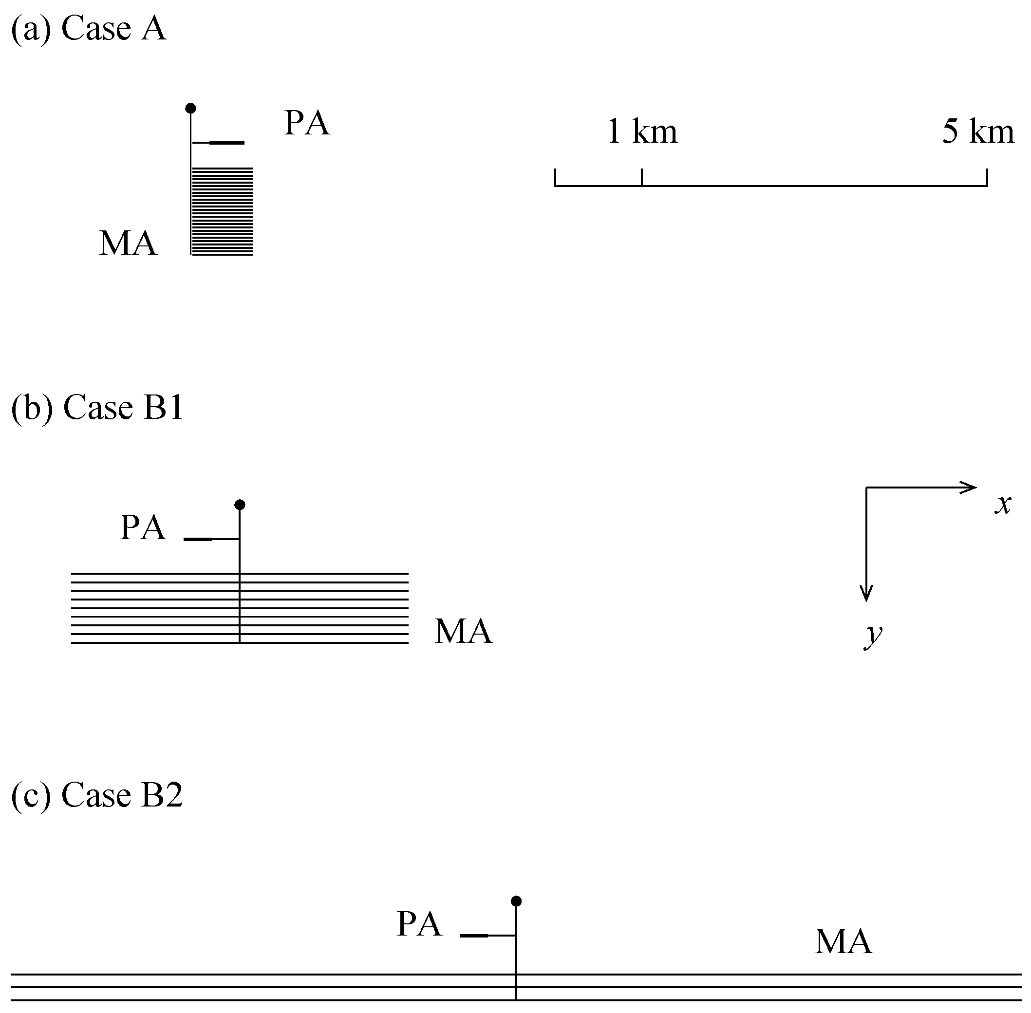
In order to investigate the effect of temperature in the safety case for high-level waste disposal, generic case A configurations shall be compared with generic case B configurations. To avoid an abstract discussion, the topic is illustrated on a particular situation. A program featuring the aforementioned characteristics is the Swiss nuclear waste management program, which is currently in the site-selection phase. For this purpose, the national cooperative for the disposal of radioactive waste (Nagra) follows a case A strategy in which the temperature cap on the outer perimeter of the bentonite is constrained to 100 °C [11] (p. 2) [12] (pp. 31–32) [13] (p. 10). The reason for the constraint is to ensure that no more than half of the smectite-rich buffer material enclosing the waste batches deteriorates during the hot phase of the repository [10] (pp. 108–109). This strategy shall be compared with two alternative case B strategies assuming the same waste inventory, case B1 and case B2 (Figure 1). Table 1 lists the essential engineering characteristics of generic (i.e., simplified but characteristic) repository layouts. Case B1 represents a concept which is a priori compatible with the current state of the Swiss program. Case B2 represents a highly optimized setting, which could not possibly be fitted in any of the remaining sites in the Swiss nuclear waste management program, but may still be an option elsewhere, as in the German sub-programs for clays and crystalline rocks (but not necessarily for rock salt, for which higher temperatures are regarded as beneficial for the compaction of backfill material [5]).
In the following, only temperature effects and their importance in the safety case are considered. Other elements of the safety case are not discussed. In particular, themes such as site selection and technical feasibility of case B configurations are not addressed. This contribution examines the role of temperature on the representativeness of pilot disposal areas, on the retrievability of waste during the operational lifetime of the facility, and on possible disturbances to neighboring aquifers. These subjects are briefly introduced below.
1.1. Retrievability of Waste
Reversibility of decisions and retrievability of waste during the operational phase of a repository warrant a prudent and risk-based approach to waste disposal [14] (p. 11). The degree of retrievability has been discussed by the Nuclear Energy Agency to depend on the operational phase in which these decisions would be taken, should it prove necessary [14] (pp. 12−13). In the Swiss setting, the Nuclear Energy Act requires that it should remain possible to retrieve the radioactive waste, both from the main field and from the pilot field, without undue effort until closure of the repository (Appendix A, Table A1). In case A, at high rock temperatures, the technical measures to implement retrieval can represent a serious challenge, especially in a setting that combines hot conditions with lack of space. This raises the question, by how much can case B concepts reduce the difficulties in the time-slot for retrieval.
1.2. Representativeness of Pilot Disposal Area
The Nuclear Energy Ordinance (Appendix A, Table A1) requires that the behaviour of waste, backfill material, and host rock must be monitored in a pilot field physically separated from the main disposal field in order to confirm (or possibly infirm) long-term safety. Necessarily, the findings in the pilot field must be representative of the processes going on in the main field as they provide the legal basis for the decision on the closure of the repository. Furthermore, the ordinance requires that the construction of the pilot section must correspond to that of the main section and that it must contain a small but representative quantity of waste. Thus, there is little room for engineering options in the setup of the pilot field once the main field has been specified. This raises the question of how well the temperatures in the pilot field represent those of the main field. Indeed, both lower or higher temperatures in the pilot area can lead to a physical evolution unrepresentative of the main disposal field and therefore to uncertainties in the interpretation of monitoring results. Since temperature effects are most often non-linear (e.g., reaction kinetics, changes in material properties, phase changes), decisions based on extrapolated data are prone to errors. Therefore, temperature conditions in the pilot field should, as far as possible, match those in the main field.
1.3. Heat-Flow Anomaly
The geological disposal of heat-generating radioactive waste generates a transient heat flow anomaly in the underground. The anomaly warms up the circumambient rock and may locally disturb the underground water system [1]. It is therefore important to acquire an understanding of the amplitude and duration of the phenomenon in geological layers where water flow is either possible or documented.
In order to obtain a tangible idea of the variation of the heat flow anomaly in time and space, we shall consider a specific geological situation, to be chosen amongst the three sites currently remaining in the Swiss nuclear waste management program. In the following, the spatial data set for the “Jura Ost” (JO) siting region is considered. The JO site features relevant rock formations for high-level waste disposal in the form of generally undisturbed, 110 m ± 25 m thick Opalinus Clay at depths between 400–600 m (top level), framed by marl, sandy clays, and limestones. Adjacent to these, the primary aquifers are the Muschelkalk (Schinznach) and Hauptrogenstein formations. These are fractured and karstified regional aquifers supplying several productive springs. Secondary aquifers are the Gansinger member (Klettgau–Fm), Beggingen member (Arietenkalk), and Passwang formations. A description of the detailed geological situation is found in [15].
According to Nagra, the closest possible aquifer to the disposal plane are calcareous layers at the base of the Passwang formation, located some 55 m above the disposal plane (estimated range 40 m to 65 m) [15] (p. 137). The closest documented aquifer to the disposal plane is the Hauptrogenstein formation located some 110 m above the disposal plane (estimated range 70 m to 155 m) [15] (p. 137). In the following, the base levels of the Hauptrogenstein and Passwang aquifers serve as references for the characterization of the heat flow anomaly.
2. Materials and Methods
2.1. Calculations
The comparison of design concepts requires fast methods to calculate the temperatures at decision-critical points in the repository. Analytical models based on the summation of Green’s functions result in fast algorithms and consistent estimates of the temperature evolution in the neighborhood of a heat source, provided that the heat transfer is macroscopically dominated by conduction. Such models can be employed to estimate the temperature evolution in the circumambient rock of a repository for spent nuclear fuel and high-level radioactive waste. Whilst they do not allow for high levels of geometrical detail, they provide exact results within the validity domain of assumptions, remain insensitive to length scales, and facilitate parameter studies. The mathematical details of the Green’s function model used in this work, together with its performance and its limitations, are presented in Appendix A of [7].
For the calculation of temperatures, a simplified waste inventory is assumed [11]. It is based on representative pressure-water reactor assemblies composed of uranium dioxide spent fuel with 40 y cooling time (75% of assemblies) and mixed-oxide spent fuel with 55 y cooling time (25% of assemblies). The spent fuel is characterized by a burnup of 48 GWd per ton of initial heavy metals (mass before irradiation). The batch charges are portioned to realize a decay power of 1500 W at the abovementioned cooling times, which we suppose to coincide with the time of underground emplacement. The production of heat decreases in time according to the laws of radioactive decay ([11] and references therein).
The analytical model is designed to take into account the most determining aspects of heat flow for the problem at hand while omitting details of secondary importance. Hence, the intensity and precise position of heat sources from radioactive decay is modeled accurately. Secondary heat sources and sinks are not considered. Furthermore, the circumambient rock, including the host rock and its confining units, is assumed to be homogeneous regarding the thermal properties. The goals, general guidance, method, and arguments for the pre- and post-closure safety cases are taken from national law (see Section 1) and the explanatory literature [16,17].
2.2. Data
The data underlying the present study are taken, whenever available, from Nagra reports. Where data are unavailable or are not yet specified, we try and make a reasonable guess for a consistent discussion. This is of concern for two parameters. The first parameter is the number of waste batches to be foreseen in the pilot disposal area of a repository for spent fuel or high-level waste. Based on legal requirements, we expect this number to range on the order of less than 1% of the radioactive inventory. The second parameter is the timing of the ultimate hold point for the decision to retrieve the waste. The safety case requires permanent protection of humans and the environment to be demonstrated before ordering the closure of the repository. We therefore estimate a period on the order of minimum of 10 y to a maximum of 100 y between the beginning of waste emplacement and the point of no return. These values should conform with the Nuclear Energy Agency’s recommendation that retrievability should ensure a prudent approach to waste disposal [14].
3. Results
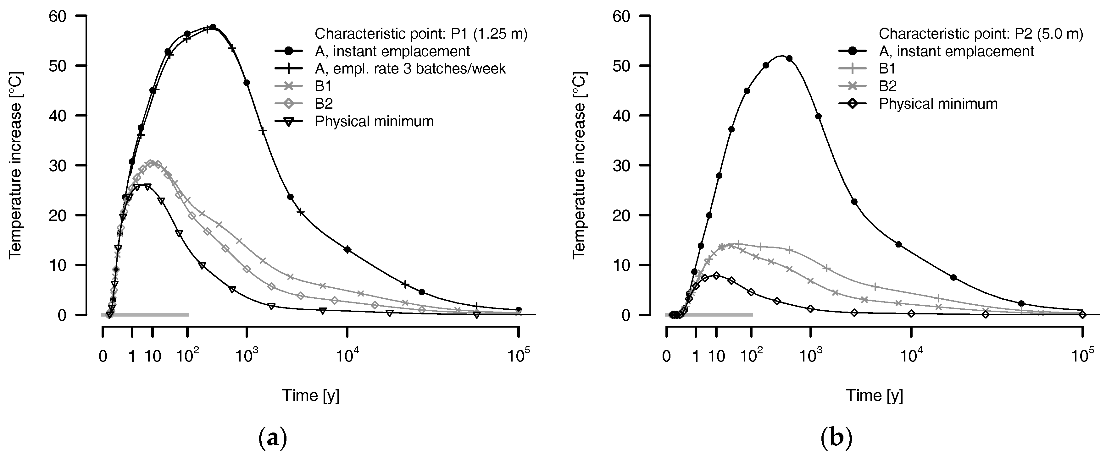
The first point to consider is the evolution of temperatures at characteristic points in case A and case B concepts. Figure 2 shows the evolution in time of the temperature pulse as expected at two test points P1 and P2. Point P1 (P2) is located 1.25 m (5.0 m) at a sideways distance (along the y-axis, Figure 1) from the barycenter of a spent fuel batch, positioned in the central area of the repository. P1 lies on the outer surface of the bentonite buffer [18] (Appendix 2) or near this surface [19] (Section 2.4). P2 lies near the maximum outer limit of the excavation damaged zone, as estimated by Nagra [19] (Section 5.3).
The evolution in time of the temperature at P1 and P2 is shown for case A and case B configurations in Figure 2. The temperature pulse strongly depends, both in amplitude and in duration, on the chosen configuration. Between case A and case B, peak values differ by 30°C at P1 to almost 40 °C at P2. (N.B. The effect of finite or infinite emplacement rates is shown quantitatively in Figure 2a for 3 batches per week (total duration of emplacement is 15 y) and instant emplacement of all batches. The origin on the time axis is taken at the time of emplacement of the batch associated with P1. The differences in temperature are too small to be relevant for the present discussion and are discarded). The curve denoted ‘physical minimum’ indicates the lowest temperature possible if batch charge and cooling times are considered constant. The physical limit corresponds to an ideal case B-setting in which individual batches are sited in infinite distance from each other (i.e., far enough to consider them as thermally insulated from each other [7]). Both case B1 and case B2 come reasonably close to the physical lower limit. By contrast, the thermal pulse in case A is laid out to satisfy the temperature cap. Accordingly, the temperature peak is far from the physical lower limit. The temperatures at P1 and P2 increase rapidly after emplacement of the waste. In case A, the temperature at P1 increases by 30 °C within the first year, by 45 °C within 10 y, and by 56 °C within 100 y. The ascending half of the temperature peak in the backfill coincides with the previously assumed time-window for retrieval, i.e., the temperatures continually increase towards the peak value in this interval. The situation is similar at P2, but somewhat retarded and with slightly inferior temperatures. The high temperatures at P2 in the aforementioned window show that a large reservoir of heat builds up in the neighborhood of the disposal gallery.
In case B, the picture is different. Here, the temperatures at P1 begin to increase as rapidly as in case A, but the regime abruptly changes after a year. At this point the rate of temperature change slows down sharply, both in case B1 and case B2. The peak amplitude of 30 °C is already reached about 10 y after waste emplacement. After that, the temperatures at P1 decrease ad infinitum. The situation is similar at P2, but again somewhat retarded and with even inferior temperatures. The descending half of the temperature peak coincides with the time-window for retrieval.
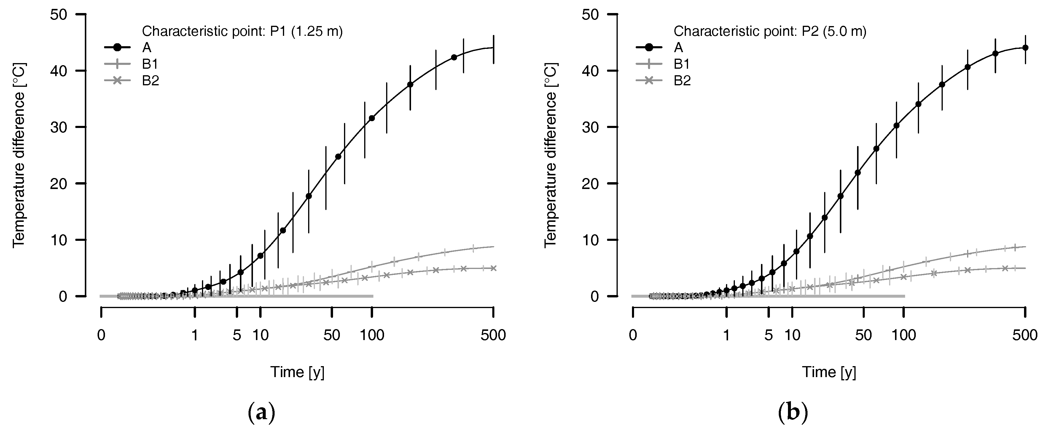
The next point to consider is the temperature differences between the pilot field and main field. The graphs in Figure 3 show the calculated temperature difference at P1 and P2 in the pilot areas with respect to the corresponding main field temperatures for case A, case B1, and case B2. Since batches in the pilot field have less neighbours than those in the main field, temperatures in the pilot field are lower. For the calculation, the construction of the pilot disposal galleries is assumed identical to that of the main section as required by the Nuclear Energy Ordinance Art. 66c. The pilot fields are supposed to hold 7 to 21 batches (<1% of inventory) in either a single row or in an arrangement of 3 rows with 7 batches each. The error bars denote the range of temperature differences considering various batch positions in the pilot field. In case A, the temperatures in the main field and the pilot field begin to diverge quickly within a few years after emplacement. The difference attains 30 °C after a hundred years and continues to increase thereafter, reaching over 40 °C after 500 y. The situation is different in case B, in which the temperatures in the main field and the pilot fields evolve almost in parallel, with main field temperatures just slightly superior to those at corresponding points in the pilot area.
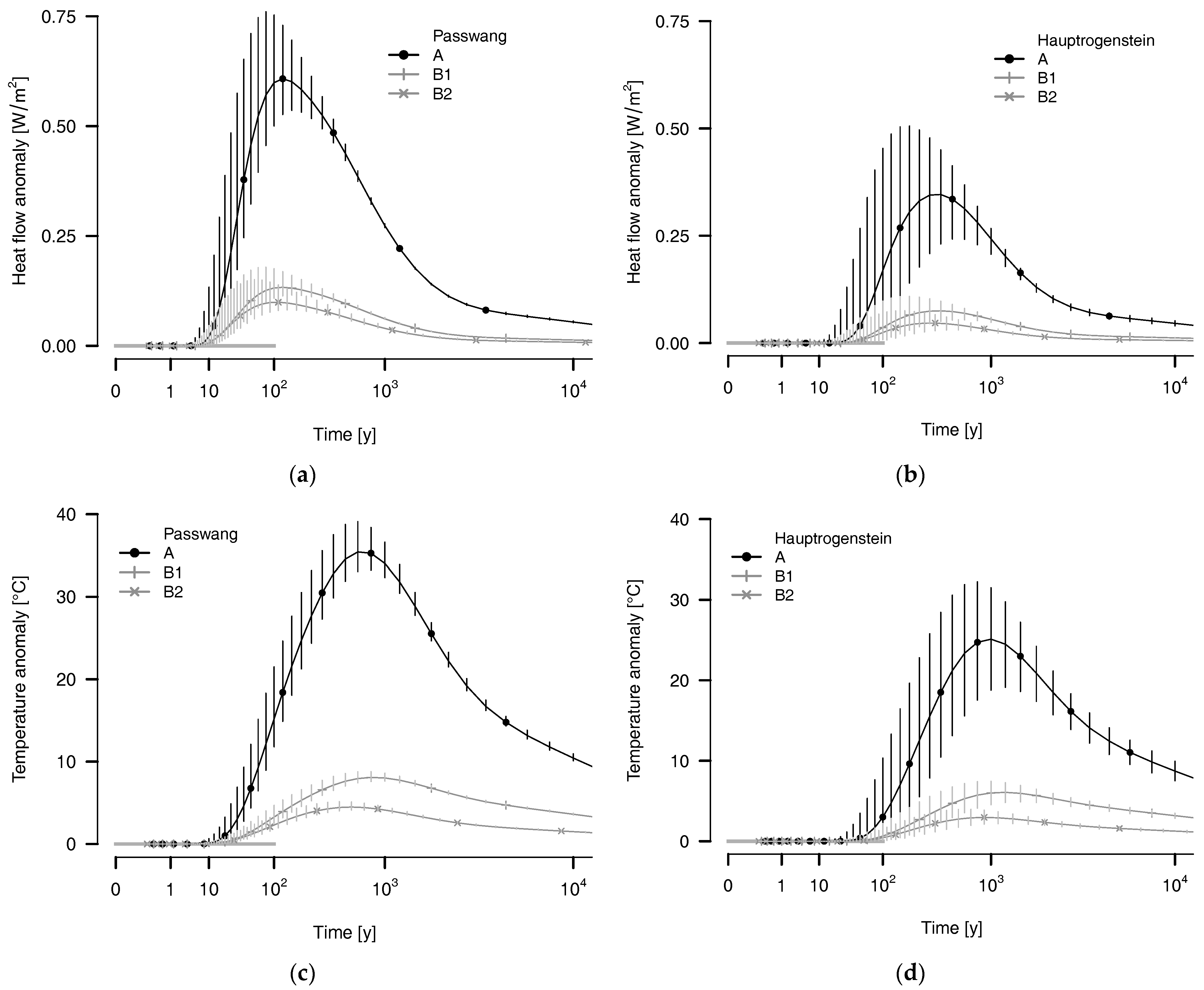
For the remainder of this section, the heat flow anomaly at the bottom of the water bearing Passwang and Hauptrogenstein formations are described. Since both the envelope size and the spatial distribution of heat sources differ in case A and case B, the anomaly is expected to depend on the configuration. The evolution in time of the anomaly in the aforementioned reference levels is shown in Figure 4. The values of the heat flow anomaly (panels a and b) and temperature anomaly (panels c and d) are computed for the intersections of these reference levels with a vertical straight line through the repository center. The error bars denote the uncertainty regarding the inexact known position of these reference levels relative to the disposal plane. The calculations are made for the limiting case in which heat transport is dominated by conduction, with negligible convective and radiative transports.
In case A, the peak amplitude of the vertical component of heat flow is expected to reach values between 0.55 and 0.75 W/m2 in the Passwang reference level and between 0.25 and 0.50 W/m2 in the Hauptrogenstein reference level. In case B1, the anomaly is much reduced, with peaks below 0.19 and 0.11 W/m2, respectively. In case B2, the anomaly is reduced again, with peaks below 0.15 and 0.08 W/m2, respectively. The peak times are expected to occur within 80 to 160 y in the Passwang reference level and within 200 to 600 y in the Hauptrogenstein reference level, regardless of configuration.
The peak temperature amplitude is expected in case A to reach values between 33 and 38 °C in the Passwang reference level and between 19 and 32 °C in the Hauptrogenstein reference level. As described above, the anomaly is much reduced in the B1 case, with peaks below 8 and 6 °C, respectively. In the B2 case, the anomaly is reduced again, with peaks below 5 and 3 °C, respectively. The peak times are expected to occur within 600 to 900 y in the Passwang reference level and within 900 to 1300 y in the Hauptrogenstein reference level, regardless of configuration.
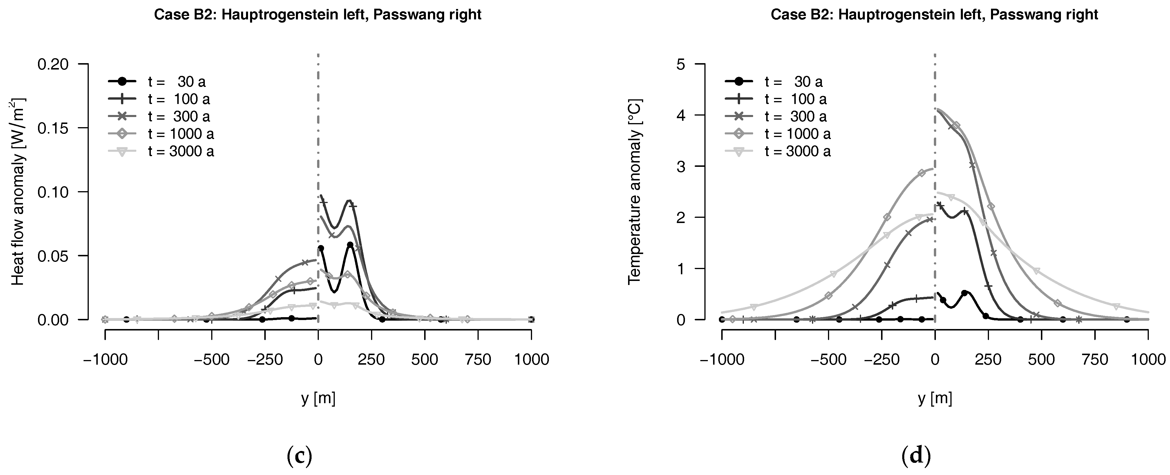
The spatial extensions of the anomalies in case A and case B2 configurations are shown for both reference levels in Figure 5. The anomalies are computed on a straight line within the reference level and orthogonal to the direction of the disposal galleries (i.e., parallel to the y-axis, Figure 1; the values at y = 0 in Figure 5 correspond to those of the solid curves in Figure 4). The anomaly profiles are computed for selected time steps between 30–3000 y. The spatial oscillations in Figure 5c,d represent the contributions from the individual disposal galleries in case B2. In case A the galleries are packed closer together and the individual contributions are not resolved (i.e., the contribution from individual batches and galleries superpose, increasing the temperature and heat flow density). The graphs show that the anomalies remain spatially confined to the neighborhood of the repository for long times. The anomalies are local and remain local as long as their amplitudes are significant. In summary, the essential difference between case A and case B resides in the much smaller amplitudes, both in the vertical component of the heat flow and in temperature in case B as compared with case A.
4. Discussion
The goal of the present study is not to predict precise values, but to describe a number of phenomena and their orders of magnitude. The specific example case taken from the Swiss nuclear waste management program serves to illustrate a number of general obstacles that lay ahead on the project timeline when following a case A or case B approach. No conclusions are specifically directed towards the Swiss management program.
4.1. Retrievability of Waste
The artificial temperature pulses expected at the reference points P1 (at or near the interface between bentonite backfill and host rock) and P2 (outer edge of excavation damaged zone) for three different repository configurations, case A, case B1, and case B2 are shown in Figure 2. The actual temperature at any point of space is the sum of the artificial temperature increase due to the repository and the natural temperature in the absence of the repository by virtue of the superposition principle for heat conduction. For the sites proposed in the Swiss nuclear waste management program, the undisturbed temperatures are expected to be between 32 °C and 52 °C. To simplify the discussion, we shall assume a value of 40 °C in the following, bearing in mind a possible variability of about 10 °C.
Under this assumption, the temperature at P1 exceeds 85 °C after 10 y and 96 °C after 100 y in case A. At points further inside the backfill, the temperatures are even higher and can exceed 100 °C. In Nagra’s current planning, waste is to be retrieved by digging into the backfill as proposed in [12] (p. 140). In this case the minimum temperature to cope with is that at P1. Alternatively, if waste were to be retrieved by digging a parallel gallery, then the temperature at P2 would be representative. At this point the temperature exceeds 75 °C after 10 y and 88 °C after 100 y. Thus, in any case, high rock temperatures must be faced. The situation is further complicated by the lack of space in galleries with 5 m2 to 6 m2 in cross-section. These must serve simultaneously (or consecutively) for digging, cooling, ventilation, and retrieval. Since tunnel driving is orders of magnitude faster than the diffusion of heat in rock or backfill material, mining work for retrieval is constantly progressing into hot volumes. Moreover, since temperatures steadily increase in case A, retrieval work is under time-pressure. In the worst possible case, ventilation can be impeded if the retrieval is carried out in presence of leakages [20] (p. 10). Despite these difficulties, the radioactive waste should remain retrievable without undue effort until the closure of the repository (Appendix A, Table A1). The combination of these factors makes the eventuality of retrieval a difficult obstacle in the planning of the facility [21]. Were it not for the high temperatures, none of the other factors seem unsurmountable.
In case B, the picture is different. Assuming again a 40 °C undisturbed temperature, the temperature at P1 peaks at 70 °C after 10 y and decreases thereafter, reaching 60 °C to 63 °C after 100 y. At P2 the temperature peaks later, 20 y after emplacement, but reaches no higher than 54 °C. Since post-peak temperatures remain stable or steadily decrease, time becomes a possible ally for retrieval. The other factors are still present, but their difficulty is mitigated by the lower temperatures.
For these reasons, we expect the legal requirement of retrievability to become a determinant factor in the further planning and general specification of the repository.
4.2. Representativeness of Pilot Disposal Areas
A decade after waste emplacement, the temperatures in the pilot area of a case A-type repository begin to differ substantially from those in the main disposal area. Since the mobility of solutes and the rates of both chemical reactions and material degradation processes are in general temperature-sensitive, the representativeness of what is going on in the pilot area is an engineering problem. Since temperature-dependencies are often non-linear in nature and the environment in which they take place is rather complex, extrapolation is difficult. For example, the rate of re-hydration of the bentonite backfill is an important factor in the safety-case for a repository which uses this material for sealing. However, re-hydration precisely affects those sealing properties and depends on temperature. The dependency is due to parameters such as the concentration and the diffusivity of water vapor and liquid water in the near-field, where temperatures differ most. The equalization of temperatures in the pilot field and main field is made more difficult if the construction of the pilot section is required to strictly correspond to that of the main section. This requirement leaves little room for engineers to adjust the temperatures, for example, by decreasing the spacing between adjacent disposal galleries in the pilot field. In our judgement, a better match in temperature is preferable to a perfect match in spatial dimensioning, as spatial re-scaling in general is not as difficult as the extrapolation to higher temperatures.
In case B-type repositories, the temperature differences between the main field and pilot field are a fraction of those in case A-type repositories (up to 5 °C for case B2 and up to 9 °C for case B1). Differences remain however, and extrapolation may still be difficult in principle, but the amplitude of the extrapolation is substantially decreased.
The representativeness of the pilot section and main section is an important element of the safety case, as it provides the legal basis for the decision on the closure of the repository [20] (p. 10). In case A, the temperature conditions in a physically separated pilot field do not closely match those in the main field. In case B, a much closer match can be achieved. The smaller temperature differences in case B with respect to case A increase the representativeness in general and do so for a considerably longer time.
4.3. Heat Flow Anomaly
The artificial heat-flow anomalies presented in the results section represents a long-lasting footprint of a repository for high-level waste. The anomalies are clearly perceptible on the level of top host rock, within the partially water-bearing Passwang formation as well as on the level of the closest regional aquifer (Hauptrogenstein and Muschelkalk).
In case A, the vertical component of repository-induced heat flow into the Hauptrogenstein aquifer peaks at 0.25 W/m2 to 0.5 W/m2 several hundred years after waste emplacement. These values can be put in relation with natural heat flow anomalies found in Northern Switzerland. These primarily occur near the margins of the Permocarboniferous troughs and range up to 0.17 W/m2 [22] within a background field varying between 0.08 W/m2 and 0.1 W/m2 [23]. This amounts to natural peak amplitudes of 0.07 W/m2 to 0.09 W/m2, which is considerably smaller than the amplitudes in case A. On the other side, the natural amplitude is comparable in magnitude with the repository-induced heat flow anomaly for case B (≤0.08 W/m2) in the Hauptrogenstein formation.
The artificial temperature anomaly expected on the base of the Hauptrogenstein aquifer is shown in Figure 4 and Figure 5. The graphs represent the upper bound of temperature reached in the absence of non-conductive heat transport (i.e., in a closed system without cold water infiltration). If water flow is induced in an open system, the magnitude of heating depends on the in- and outflow of water. Either way, disturbances of the deep water system must be expected.
The key question is how much disturbance is tolerable, both in temperature and heat flow. Two obstacles to satisfactorily assess this question at present are the often incomplete knowledge of deep water systems (e.g., regional extent, residence time, flowpath network, etc.) as well as a somewhat unclear legislation for the problem at hand [24]. In the Swiss example, the Waters Protection Act and the Waters Protection Ordinance (WPA and WPO, Appendix A, Table A2) regulate the use of surface-bound and underground waters. The legislation is not as explicit for deep waters as it is for surface waters and near-surface groundwater. According to the WPO, an alteration of the groundwater temperature of more than 3 °C from its natural state is prohibited (Appendix A, Table A2). It is understood that, while specifying this policy, the legislative authority did have a heat input/removal by water infiltration/exfiltration in mind and not a large scale underground facility. Yet it is a basic principle of water protection in particular and environmental protection in general to keep the disturbance of the natural state as small as possible. Consulting Figure 4c,d, it can be seen that the temperature anomaly associated with case A is well above the 3 °C level whereas those associated with case B are close to this level. Despite the WPO not being directly applicable to repository-induced heat flow and temperature anomalies, there is a strong public interest for a detailed assessment of the physical effects of the thermal anomalies in regional aquifers and the mitigation thereof.
Changing the temperature in the aquifers implies that the depending physical parameters change accordingly. Changes in density and viscosity of water might affect the general flow regime and flow pattern of the groundwater system: currents through steep-dipping faults or other pathways might be initialized [25] (p. 311), microbiological activity as well as the solubility of different salts may be affected, leading to changes in mineralization and water quality. Furthermore, thermal pressurization in circumambient rock [3] is subject to recent research regarding the potential for triggering seismicity on pre-existing faults [26]. There are significant open questions concerned with the physical implications in several hundred years when the thermal anomalies (or their rates and gradients) are at their peak.
While the effect of the heat pulse in the near-field is the object of ongoing research (with the main focus on safeguarding the barrier function in the near field of the repository), far field effects on distant fluid bodies have not yet received a comparable level of attention. Research in this direction, with the aim of understanding those effects, especially on nearby aquifers, should be intensified. Of all measurable effects, the heat-flow and temperature anomalies, in combination with its effects on the water system, may represent the strongest mid- to long-term artificial footprint of a repository for heat-generating radioactive waste. Hereby, the amplitude of the anomalies in the aquifers can be re-scaled by engineering choices for the layout of the underground facility, as far as the safety case is not impeded.
5. Conclusions
The disposal of heat-generating radioactive waste in deep underground facilities requires a sparing use of spatial resources and favorable temperature conditions. Under heat-sensitive disposal strategies, these goals run in opposite directions and therefore a balance of some kind must be found. In the present study, two basic strategies are compared: A space-saving strategy conditioned by the capping of temperatures for critical barrier components of the repository (case A) and a low-temperature strategy aiming to reduce temperatures globally as long as supplementary benefits are returned from doing so (case B).
The main purpose of the case B strategy is to slow down the deterioration of materials undergoing thermally activated degradation processes. In three respects, additional benefits to the case B strategy over the prevailing case A strategy have been identified. These are: 1. case B configurations feature substantially lower temperatures for operations taking place in the time-slot for waste retrieval than case A configurations. Thus, if the demonstration of retrievability is required by the safety case, this may become a determinant factor in the further planning and specification of the repository. 2. The temperatures in the case B configurations are more equalized between the main disposal field and pilot field, resulting in improved representativeness of the monitoring activity in the pilot field. 3. The amplitudes of thermal anomalies underground are substantially reduced, both in the near-field, affecting the barrier system, and in the far-field, affecting aquifers. The response of distant fluid bodies to the perturbations caused by a repository for high-level nuclear waste and spent fuel should be part of the comprehensive and site-specific description of a siting region.
The difficulties with higher temperatures associated with case A concepts can be re-scaled by engineering choices for the layout of the underground facility. This may induce new difficulties associated with increased spatial needs. However, at present, the right balance between saving spatial resources and obtaining favorable temperature conditions for all planned activities is yet to be determined.
Acknowledgments
This work was supported by the State Council of the Canton of Schaffhausen and by the Department of Environment (BVU) of the Canton of Aargau, Switzerland.
Author Contributions
Joachim Heierli conceived and carried out the calculations. Oliver Genoni wrote the sections relating to the heat flow anomaly.
Conflicts of Interest
The authors declare no conflict of interest. The founding institutions had no role in the design of the study; in the collection, analyses, or interpretation of data; in the writing of the manuscript, and in the decision to publish the results.
Appendix A

Table A1.
Excerpts from the Nuclear Energy Act 732.1 of 21 March 2003 (Status as on 1 July 2016, Federal Assembly of the Swiss Confederation) and of the Nuclear Energy Ordinance 732.1 of 10 December 2004 (Status as on 1 July 2016, Federal Council).
Table A1.
Excerpts from the Nuclear Energy Act 732.1 of 21 March 2003 (Status as on 1 July 2016, Federal Assembly of the Swiss Confederation) and of the Nuclear Energy Ordinance 732.1 of 10 December 2004 (Status as on 1 July 2016, Federal Council).
| Document | Legal Text 1 (Extract) |
|---|---|
| Nucl. Energy act, Chap. 5, Sec. 3 | Art. 37 1b. An operating licence for a deep geological repository is granted if […] it is possible to retrieve the radioactive waste without undue effort until closure of the repository. |
| Nucl. Energy Ordinance, Chap. 5, Sec. 3. | Art. 62 a. […] applicants for a general licence for a deep geological repository must also submit a report containing […] a comparison of available options from the point of view of safety of the planned repository; |
| Nucl. Energy Ordinance, Chap. 5, Sec. 3 | Art. 66 1. In the pilot installation, the behaviour of waste, backfill material and host rock must be monitored until the expiry of the monitoring period. During monitoring, data must be collected in order to confirm long-term safety with a view to closure. Art. 66 2. […] The obtained findings must be transferable to the processes going on in the main section. They form the basis for the decision on the closure of the repository. |
| Art. 66 3c. The construction of the pilot section and the emplacement procedure of waste and backfill material must correspond to those of the main section. | |
| Art. 66 3d. The pilot section must contain a small but representative quantity of waste. |
1 The English translation provided by the administration has no legal force.
Table A2.
Excerpts from the Waters Protection Act 814.20 of 24 January 1991 (Status as on 1 January 2017, Federal Assembly of the Swiss Confederation) and of the Waters protection Ordinance 814.201 of 28 October 1998 (Status as on 2 February 2016, Federal Council).
Table A2.
Excerpts from the Waters Protection Act 814.20 of 24 January 1991 (Status as on 1 January 2017, Federal Assembly of the Swiss Confederation) and of the Waters protection Ordinance 814.201 of 28 October 1998 (Status as on 2 February 2016, Federal Council).
| Document | Legal Text 1 (Extract) |
|---|---|
| Federal Act on the Protection of Waters | Art. 2. This Act applies to all surface and underground waters. Art. 4. Definitions: b. underground waters: means groundwater (including spring water), aquifer, lower and upper confining bed. |
| Waters Protection Ordinance | Art. 1, Abs. 1. This ordinance shall facilitate the protection of surface and underground waters from harmful effects and enable their sustainable use. Art. 1, Abs. 2. For this purpose, all measures taken under this ordinance must take account of the ecological goals for waters (Annex 1). Annex 1 sect. 2, 3a. The groundwater quality shall be such that the temperature conditions are near natural; Annex 2, sect. 2, sect. 21, 3. The introduction or withdrawal of heat must not alter the temperature of the groundwater by more than 3 °C above or below the temperature in its natural state; this does not apply to very local changes in temperature. |
1 The English translation provided by the administration has no legal force.
References
- Hirano, F; Sato, S.; Kozaki, T.; Inagaki, Y.; Iwasaki, T.; Ohe, T.; Kato, K.; Kitayama, K; Torikai, S.; Niibori, Y.; et al. Thermal impact on geological disposal of hull and end piece wastes resulting from high-burn-up operation of LWR and introduction of MOX fuels into LWR. J. Nucl. Sci. Technol. 2009, 46, 443–452. [Google Scholar] [CrossRef]
- Wakasugi, K.; Ishiguro, K.; Ebashi, T.; Ueda, H.; Koyama, T.; Shiratsuchi, H.; Yashio, S.; Kawamura, H. A methodology for scenario development based on understanding of long-term evolution of geological disposal systems. J. Nucl. Sci. Technol. 2012, 49, 673–688. [Google Scholar] [CrossRef]
- Zheng, L.; Rutqvist, J.; Birkholzer, J.T.; Liu, H.H. On the impact of temperatures up to 200 °C in clay repositories with bentonite engineer barrier systems: A study with coupled thermal, hydrological, chemical, and mechanical modeling. Eng. Geol. 2015, 197, 278–295. [Google Scholar] [CrossRef]
- Beswick, A.J.; Gibb, F.B.F.; Travis, K.P. Deep borehole disposal of nuclear waste: Engineering challenges. Proc. Inst. Civ. Eng. Energy 2014, 167, 47–66. [Google Scholar] [CrossRef]
- Mönig, J.; Beuth, T.; Wolf, J.; Lommerzheim, A.; Mrugalla, S. Preliminary safety analysis of the Gorleben site: Safety concept and application to scenario development based on a site-specific features, events, and processes (FEP) database. Presented at Waste Management Conference, Phoenix, AZ, USA, 24–28 February 2013. [Google Scholar]
- Cho, D.-K.; Lee, Y.; Lee, J.-Y.; Choi, J. Characteristics of a geological disposal system for the increasing burn-up of spent nuclear fuel in Korea. J. Nucl. Sci. Technol. 2007, 44, 1306–1316. [Google Scholar] [CrossRef]
- Heierli, J. A comparative study of engineering options for the disposal of high-level radioactive waste with regard to thermal effects and chemical degradation. J. Nucl. Sci. Technol. 2016, 53, 1276–1295. [Google Scholar] [CrossRef]
- Huang, W.L.; Longo, J.M.; Pevear, D.R. An experimentally derived kinetic model for smectite-to-illite conversion and its use as a geothermometer. Clays Clay Min. 1993, 41, 162–177. [Google Scholar] [CrossRef]
- Lalan, P.; Dauzères, A.; DeWindt, L.; Bartier, D.; Juuso Sammaljärvi, J.; Barnichon, J.-D.; Techer, I.; Detilleux, V. Impact of a 70 °C temperature on an ordinary portland cement paste/claystone interface: An in situ experiment. Cem. Concr. Res. 2015, 83, 164–178. [Google Scholar] [CrossRef]
- Bradbury, M.H.; Berner, U.; Curti, E.; Hummel, W.; Kosakowski, G.; Thoenen, T. The Long Term Geochemical Evolution of the Nearfield of the HLW Repository; Technical Report No. NTB 12-01; National Cooperative for the Disposal of Radioactive Waste: Wettingen, Switzerland, 2014. [Google Scholar]
- Johnson, L.H.; Niemeyer, M.; Klubertanz, G.; Siegel, P.; Gribi, P. Calculations of the Temperature Evolution of a Repository for Spent Fuel, Vitrified High-Level Waste and Intermediate Level Waste in Opalinus Clay; Report No. NTB 01-04; National Cooperative for the Disposal of Radioactive Waste: Wettingen, Switzerland, 2002. [Google Scholar]
- Nagra. Entsorgungsnachweis für Abgebrannte Brennelemente, Verglaste Hochaktive Sowie Langlebige Mittelaktive Abfälle; Report No. NTB 02-02; National Cooperative for the Disposal of Radioactive Waste: Wettingen, Switzerland, 2002. (In German) [Google Scholar]
- Nagra. Prüfung der Lager- und Barrierenkonzepte; Report No. NAB 16-42; National Cooperative for the Disposal of Radioactive Waste: Wettingen, Switzerland, 2016. (In German) [Google Scholar]
- Nuclear Energy Agency. Reversibility of Decisions and Retrievability of Radioactive Waste. NEA Report No. 7085. Available online: https://www.oecd-nea.org/rwm/reports/2012/7085-reversibility.pdf (accessed on 12 June 2017). (In German).
- Nagra. Geologische Grundlagen. Barriereneigenschaften der Wirt- und Rahmengesteine; Nat; Report No. NTB 14-02, Dossier VI; National Cooperative for the Disposal of Radioactive Waste: Wettingen, Switzerland, 2014. [Google Scholar]
- Nagra. Demonstration of Disposal Feasibility for Spent Fuel, Vitrified High-Level Waste and Long-Lived Intermediate-Level Waste (Entsorgungsnachweis); Project Opalinus Clay Safety Report. Report No. NTB 02-05; National Cooperative for the Disposal of Radioactive Waste: Wettingen, Switzerland, 2002; pp. 319–340. [Google Scholar]
- NEA. The Nature and Purpose of the Post-Closure Safety Cases for Geological Repositories. Available online: https://www.oecd-nea.org/rwm/reports/2013/78121-rwn-sc-brochure.pdf (accessed on 12 June 2017).
- Nagra. Vorschlag geologischer Standortgebiete für das SMA- und das HAA-Lager. Begründung der Abfallzuteilung, der Barrierensysteme und der Anforderungen an die Geologie; Report No. NTB 08-05; National Cooperative for the Disposal of Radioactive Waste: Wettingen, Switzerland, 2008. (In German) [Google Scholar]
- Nagra. Beurteilung der Tiefenlage in Bezug auf die geotechnischen Bedingungen: Grundlagen für die Abgrenzung und Bewertung der Lagerperimeter; Report No. NAB 14-81; National Cooperative for the Disposal of Radioactive Waste: Wettingen, Switzerland, 2002. (In German) [Google Scholar]
- ENSI. Spezifische Auslegungsgrundsätze für geologische Tiefenlager und Anforderungen an den Sicherheitsnachweis; Report No. ENSI-G03; Eidgenössisches Nuklearsicherheitsinspektorat: Brugg, Switzerland, 2009. [Google Scholar]
- Grave, D.F.H.; Stroh, R.M. The planning of Ventilations and Refrigeration requirements in Deep mines. J. S. Afr. Inst. Min. Met. 1972, 6, 171–186. [Google Scholar]
- Schärli, U.; Rybach, L. Erstellung einer aktuellen Karte des Temperaturgradienten und des Wärmeflusses in der Nordschweiz; Report. No. NIB 02-26; National Cooperative for the Disposal of Radioactive Waste: Wettingen, Switzerland, 2002. (In German) [Google Scholar]
- Ollinger, D.; Badoux, V.; Becker, J. Report No. NAB 14-18; Temperatur- und Wärmeflusskarten für definierte Horizonte im Untergrund der Nordostschweiz; National Cooperative for the Disposal of Radioactive Waste: Wettingen, Switzerland, 2014. (In German) [Google Scholar]
- Burger, H. Nutzung und Schutz von Tiefengrundwasser im Spannungsfeld von Chancen, Risiken, Konflikten und regulatorischen Anforderungen. Swiss. Bull. Angew. Geol. 2016, 21, 69–90. (In German) [Google Scholar]
- Turcotte, D.L; Schubert, G. Geodynamics, 3rd ed.; Cambridge University Press: Cambridge, UK, 2014; p. 311. [Google Scholar]
- Urpi, L.; Rinaldi, A.P.; Wiemer, S. Potential for induced seismicity from the operation of a deep geological repository. In Proceedings of the Presented at Second Induced Seismicity Workshop, Davos, Switzerland, 14–17 March 2017. [Google Scholar]
Figure 1.
Generic repository designs from the top view; (a) case A repository with a roughly square disposal room area; (b) moderately stretched, case B1 repository composed of eighteen disposal galleries, head-to-head in pairs; (c) extremely stretched case B2 repository composed of six disposal galleries, head-to-head in pairs. MA: main disposal room area (envelope of disposal galleries). PA: pilot disposal room area; Coordinate system: The z-axis is perpendicular to the disposal plane and pointing downwards.

Figure 2.
Comparison of temperature pulses in 1.25 m (a) and 5.0 m (b) horizontal distance from the barycenter of the center batch in the case A, case B1, and case B2 configurations. The grey bottom line indicates the pre-closure phase, assumed to last up to 100 y.
Figure 2.
Comparison of temperature pulses in 1.25 m (a) and 5.0 m (b) horizontal distance from the barycenter of the center batch in the case A, case B1, and case B2 configurations. The grey bottom line indicates the pre-closure phase, assumed to last up to 100 y.

Figure 3.
Temperature difference between the pilot field and main field in repository configurations case A, case B1, and case B2; (a) at P1; (b) at P2.
Figure 3.
Temperature difference between the pilot field and main field in repository configurations case A, case B1, and case B2; (a) at P1; (b) at P2.

Figure 4.
Comparison of thermal anomalies as expected at the reference levels for case A (black) and case B1 and B2 (grey) at the JO site (see Section 1.3); (a,b) Heat flow anomaly; (c,d) Temperature anomaly in the absence of convective heat transfer.
Figure 4.
Comparison of thermal anomalies as expected at the reference levels for case A (black) and case B1 and B2 (grey) at the JO site (see Section 1.3); (a,b) Heat flow anomaly; (c,d) Temperature anomaly in the absence of convective heat transfer.

Figure 5.
Examples of calculated y-profiles of heat flow and temperature anomalies at the possible water-bearing reference levels of the JO site; (a,b) case A; (c,d) case B2. Left side (y < 0): Hauptrogenstein reference level; right side (y > 0): Passwang reference level.
Figure 5.
Examples of calculated y-profiles of heat flow and temperature anomalies at the possible water-bearing reference levels of the JO site; (a,b) case A; (c,d) case B2. Left side (y < 0): Hauptrogenstein reference level; right side (y > 0): Passwang reference level.
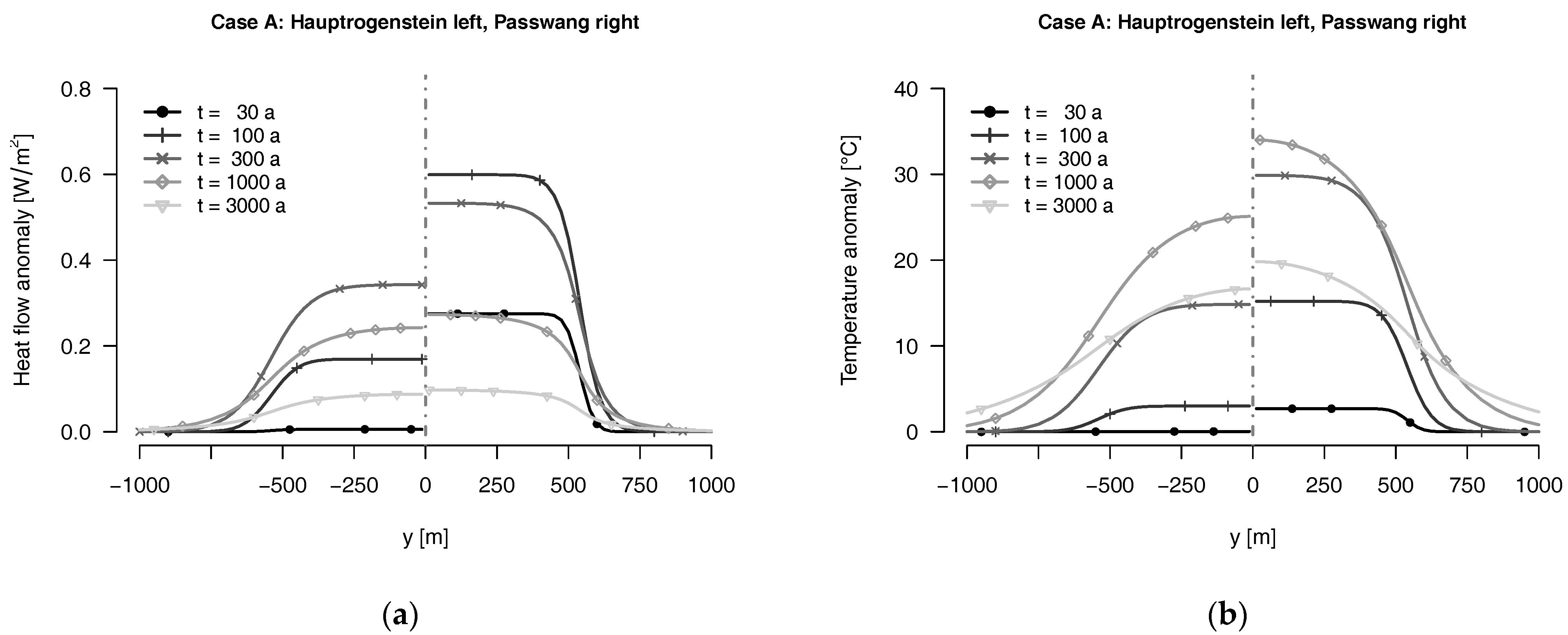

Table 1.
Outline characteristics of space-optimized (case A) and low-temperature (case B) configurations for the disposal of high-level waste and spent fuel in Opalinus clay.
Table 1.
Outline characteristics of space-optimized (case A) and low-temperature (case B) configurations for the disposal of high-level waste and spent fuel in Opalinus clay.
| Design parameters | Case A 1 | Case B1 | Case B2 |
|---|---|---|---|
| Number and length of disposal galleries | 27 × 0.7 km | 18 × 1.95 km | 6 × 5.9 km |
| Total length of disposal galleries | 18.9 km | 35.1 km | 35.4 km |
| Envelope size of total disposal room area 2 | 0.72 km2 | 3.1 km2 | 3.5 km2 |
| Siting period for waste batches | 8 m | 15 m | 15 m |
| Distance of adjacent disposal galleries | 40 m | 100 m | 150 m |
| Initial line power density 3 | 188 W/m | 100 W/m | 100 W/m |
| Initial area power density 4 | 4.9 W/m2 | 1.1 W/m2 | 1 W/m2 |
| Number of gallery junctions | 27 | 9 | 3 |
| Total number of waste batches 5 | 2349 (27 × 87) | 2349 (9 × 261) | 2349 (3 × 783) |
| Thermal conductance of circumambient rock | kx = ky = 3.2 W/mK (hor.); kz = 1.6 W/mK (vert.) | ||
| Volumetric heat capacity of circumambient rock | 2.3 MJ/m3K | ||
© 2017 by the authors. Licensee MDPI, Basel, Switzerland. This article is an open access article distributed under the terms and conditions of the Creative Commons Attribution (CC BY) license (http://creativecommons.org/licenses/by/4.0/).
Share and Cite
MDPI and ACS Style
Heierli, J.; Genoni, O. The Role of Temperature in the Safety Case for High-Level Radioactive Waste Disposal: A Comparison of Design Concepts. Geosciences 2017, 7, 42. https://doi.org/10.3390/geosciences7020042
AMA Style
Heierli J, Genoni O. The Role of Temperature in the Safety Case for High-Level Radioactive Waste Disposal: A Comparison of Design Concepts. Geosciences. 2017; 7(2):42. https://doi.org/10.3390/geosciences7020042
Chicago/Turabian StyleHeierli, Joachim, and Oliver Genoni. 2017. "The Role of Temperature in the Safety Case for High-Level Radioactive Waste Disposal: A Comparison of Design Concepts" Geosciences 7, no. 2: 42. https://doi.org/10.3390/geosciences7020042
Note that from the first issue of 2016, this journal uses article numbers instead of page numbers. See further details here.