Measurements versus Numerical Simulations for Slotted Synthetic Jet Actuator


Department of Industrial Engineering, Aerospace Sector, Universitá degli Studi di Napoli “Federico II”, p.le Tecchio 80, 80125 Naples, Italy
*
Author to whom correspondence should be addressed.
Actuators 2018, 7(3), 59; https://doi.org/10.3390/act7030059
Submission received: 25 July 2018
/
Revised: 7 September 2018
/
Accepted: 10 September 2018
/
Published: 11 September 2018
(This article belongs to the Special Issue Synthetic Jet Actuators)
Abstract
:In many studies concerning synthetic jet flow fields the analysis is usually restricted to simple configurations, such as a single diaphragm oscillating in a cylindrical cavity, which is linked to the external environment with only one orifice/slot. Nonetheless, in many applications the requirement of small sizes and weights leads to many implementation issues, such as asymmetric actuator geometries, presence of several slots and diaphragms and irregular cavity shapes. Therefore, the design of a synthetic jet actuator for a specific flow control problem requires a dedicated study in order to characterize its behavior even in quiescent conditions. The aim of this work is to investigate the behavior of a novel synthetic jet actuator, composed of three independent diaphragms, acting on a single cavity, and linked to the external environment through four slots per diaphragm. The device has been studied in quiescent conditions, both numerically and experimentally. The experimental investigation has been carried out by means of hot-wire measurements. In particular, the distribution of the phase-averaged streamwise velocity along the slot spanwise direction has been detected near the slot exit plane. From the computational side, incompressible direct numerical simulations have been carried out using the open-source OpenFOAM code. The diaphragm motion is mimicked by a inhomogeneous inlet boundary condition, whose amplitude is chosen to match the experimental velocity at the exit plane. A fair agreement between the numerical and the experimental results is achieved for both the velocity field at the slot exit and the main non-dimensional parameters of the synthetic jet. After the validation, the numerical results are finally processed, to obtain information about the vortex motion in the external environment.
1. Introduction
It is known that the generation of synthetic jets (SJ) does not require any continuous fluid supply, because the jet is synthesized directly from the surrounding fluid [1,2]. This feature has made this technology interesting among the main active flow control techniques [3] for applications where low weights and reduced sizes are required. Indeed, SJ actuators have been largely employed in several industrial applications as impinging jets (due to their enhanced mixing [4] and heat transfer [5] coefficients with respect to continuous jets); to control jets [6,7] and sprays [8]; to suppress separated flows [9] and optimize drag and lift on airfoils [10,11]. A huge bulk of literature papers can be found in cross-references of the mentioned articles. For this reason, several experimental, numerical and theoretical studies have been devoted to the analysis of the flow fields generated by an SJ actuator. In this work the investigation is concerned with a particular novel type of slotted piezo-driven actuator.
Experimental analyses have been mainly focused on comparing the SJ flow fields to continuous jets [4,12,13], evaluating the efficiency of the device [14], and demonstrating the effectiveness of the device as a flow control technique [15,16,17]. Hot-Wire Anemometry [4,18], Laser Doppler Velocimetry [19], Particle Image Velocimetry [20,21], and flow visualization techniques [18,22] have been usually employed for this purposes. On the other hand, many computational studies of synthetic jets have been carried out, using two-dimensional RANS techniques [23], or three-dimensional DNS [24,25] and LES [9] computations, both in quiescent environment or in crossflow. Finally, another practical approach is the definition of a lumped element model (LEM), able to obtain the time variation of the thermodynamic variables inside the cavity and the exit velocity with a good accuracy and in a short time [26,27].
Most of the works concerning the application of SJ actuators to flow control are focused on the design and characterization of a single-orifice and/or single-cavity actuator, while in many practical situations it is necessary to use more complex configurations. First of all, different cavity shapes require a specialized study, since their behavior cannot be completely predicted by simple models: a very recent research line concerns the effect of the actuator geometry on the synthetic jet characteristics [28,29,30].
Moreover, in many applications slotted configurations are preferred to circular orifices. The specialized literature reports contributions referring to both single long slots running all over the spanwise direction of the flow to be controlled [12,20], and discrete evenly spaced orifices [31,32,33]. In [31], three rows of synthetic jets actuators were mounted along the span of a finite wing; in this case, there are as many slots as diaphragms, since different slots are located on the edge of different cavities. Similarly, in [32], the authors aimed to design an array of 30 synthetic jet actuators and place them within the flap of a three-element wing model. Finally, in [33], a segmented synthetic jet actuator was used to control the flow on a NACA 4421 airfoil at zero angle of attack. The slot of the synthetic jet has been segmented in two equal pieces (along the wingspan) to study the vortical structures generated by the edges of the slits (using LES). The flow fields obtained varying the gap between the slots were then compared with the one obtained with a single slot in the same crossflow conditions (and same total exit area).
The objective of this work is to study the flow field generated by an innovative slotted device, realized with three independent diaphragms (applied at the bottom of a single cavity) and linked to the external environment through four slots for each diaphragm. This configuration is studied in quiescent conditions, both experimentally and numerically. The present work is mandatory to exploit the SJ actuator for control purposes (for example, to control a separated flow). It is worth noting that this configuration is different from the ones chosen by [31,32], who designed an array of synthetic jet actuators. The use of three shorter diaphragms instead of a single, long piezo-element assures a more homogeneous external flow field along the spanwise direction. Moreover, the piezo-elements are easily accessible for maintenance in this configuration, and their replacement does not involve the top part of the actuator, which contains the slots.
The expected external flow field is more complex than for a single-slotted actuator, since it is characterized by several vortical structures which eventually interact with each other. Moreover, previous studies [20,22] showed that each vortex train, even for a single-slotted actuator, seems to vary its orientation when moving downstream (axis switching), yielding a very complex topology of the vortex system in the external environment.
The paper is organized as follows. Section 2 deals with the description of the actuator geometry and the experimental setup. The unconventional configuration chosen for the actuator is also discussed with respect to other approaches found in literature. The section ends with the introduction of the main SJ non-dimensional parameters. Section 3 concerns the numerical analysis setup. In Section 4.1 a comparison between numerical and experimental results is made, to validate the numerical simulation. Then, in Section 4.2, the numerical data is used to characterize the external flow field. Finally, conclusions are made in Section 5.
2. Experimental Characterization
2.1. The SJ Device
The device, with the exception of the diaphragms, has been entirely made in-house. Figure 1 shows the bottom (a) and the top (b) views of the actuator. It is based on a stainless steel sandwich structure: the top part, with dimensions of 261 × 70 mm2, contains twelve slots; a flat rectangular ring is used to create a single cavity, under which three piezo-speakers are applied; the bottom part has been designed only to provide a structural support to the piezo-elements. The geometrical characteristics of the actuator are depicted in Figure 2: the slot is mm wide, its spanwise length is mm, and its depth is mm. The distance between two consecutive slots of the same group is mm, whereas two adjacent slot rows are distant from each other by = 11.85 mm. The cavity depth is = 2 mm, and it is bigger than the depth of the interconnecting zone between the three actuator parts, which is = 1 mm. The piezo-speaker support is 2 mm thick, thus the overall thickness of the device is equal to 5 mm. The piezo-speakers are Sonitron SPS-8770-03, equipped with a multi-layer (polymer/metal) diaphragm embedded in a plastic support whose dimensions are 70 × 87 mm2, and their operating frequency ranges up to 20 kHz. This configuration has been preferred to other approaches found in literature, the multi-slot, single-diaphragm configuration, and the array of synthetic jet actuators. The main advantage of this configuration with respect to the single-diaphragm one is a more uniform distribution of the pressure within the cavity and the diaphragm displacement along its span. This feature yields comparable exit velocities between the slots (whereas, using a long, single piezo-element, the exit velocity of the external slots would be much smaller than the central ones). On the other hand, the practical realization and the maintainance of this actuator is simpler than an array of synthetic jet devices.
The reference system used hereafter is shown in Figure 2. Its origin is located in the middle of the intersection line between the symmetry plane and the cavity exit plane. The x axis moves downstream within the symmetry plane, the y axis goes in the spanwise direction, and the z axis is in the exit plane, orthogonal to the previous two ones.
In the present work the piezoelectric elements have always been electrically excited at an actuation frequency f = 250 Hz, which is the structural resonance frequency of the oscillating diaphragm. This value of the operating frequency has been chosen to match the desired values of reduced frequency (Equation (1)) and momentum coefficient (Equation (2)), in order to perform an optimal control of the flow over a backward-facing ramp [34]. In Equations (1) and (2) is the flow separation length, the freestream velocity, the jet exit velocity, and and the total area of the actuators and the surface of the ramp. In the following the jet exit velocity will be also referred to as , which is the peak jet velocity per cycle. Since the value of the actuation frequency is constrained by this requirement, the device have been designed to have a structural resonance frequency equal to 250 Hz, maximizing the jet exit velocity in the operating conditions.
2.2. Experimental Methodology
The external flow field generated by the SJ actuator has been investigated using the hot-wire anemometry technique. The aim of the study has been to completely characterize the behavior of an inner slot, by means of phase-averaged quantities, and compare the results with the simulations.
The actuator has been electrically excited by a sine signal, generated through a USB Instruments DS1M12 or “Stingray”. This device can work simultaneously as a signal generator and a data acquisition system. The signal is then transmitted to a linear amplifier (EPA-104, Piezo System Inc., Woburn, MA, USA), which gives the correct value of the applied voltage to the piezo-elements. In the present experiments the amplitude of the electrical signal is equal to = 30 V, which is the maximum operating voltage of the piezo-elements. The streamwise jet velocity was measured by means of an hot-wire anemometer (Dantec Dynamics, MiniCTA, Skovlunde, Denmark), equipped with a 5 µm diameter, 1.25 mm long wire probe. Its output signal was acquired by the same data-acquisition system used to generate the electric signal, with a sampling rate of 10 kHz, for 2000 operating cycles. An estimation of the experimental uncertainty of the hot-wire data has been made following Yavuzkurt’s work [35]. The uncertainty in the phase-averaged streamwise velocity is found be less then 3% for all the measured values.
In particular, the characterization of the second slot (from the external side of the plate) has been carried out, placing the probe parallel with the slot width, and moving it along x and y directions, to obtain the distribution of the streamwise velocity. The measurements have been collected with a 0.5 mm step along the spanwise direction, and with a 0.2 mm step along the streamwise direction. The experimental data set, then, consists in 40 phase-averaged streamwise velocity profiles along the y axis, collected in 11 locations at different distances from the slot exit plane. The results of the experiments are reported and discussed in Section 4, where they will be used as reference values to calibrate the numerical simulations.
2.3. Non-Dimensional Parameters
The distribution of phase-averaged streamwise velocity at one of the slot exits allows the evaluation of a reference velocity , defined by means of Equation (3).
where is the actuation period and is the exit area of a single slot. This velocity is generally referred to as averaged jet velocity in the specialized literature [4]. It is used, along with the kinematic viscosity , to define the jet Reynolds number, the (flow) Strouhal number and the Stokes number, defined by Equations (4)–(6).
Only two of these non-dimensional numbers are sufficient to characterize the SJ behavior, since they are related by the following identity: . Moreover, the dimensionless stroke length can be conveniently introduced: . All these parameters have been evaluated both from the hot-wire data and the numerical results with reference to the second slot exit. The average jet velocity is equal to 2.85 m/s, which corresponds to a peak exit velocity at the centerline of about 9 m/s. The main dimensional and non-dimensional parameters are summarized in Table 1. It is worth to note that, for the present flow conditions, synthetic jets are formed a few slot widths far away from the exit plane.
3. Computational Setup
The flow field generated by the SJ actuator was studied by means of an incompressible, direct numerical simulation, performed with the open-source code OpenFOAM [36]. The native incompressible flow solver pimpleFoam was selected for the simulation. This solver is based on the PIMPLE algorithm, a merging of the PISO and the SIMPLE algorithm. The computational setup is similar to the one used in [37]: the spatial discretization is based on a finite-volume approach, where both convective and diffusive terms are approximated by second-order centered schemes. The pressure linear system is solved by a generalized geometric-algebraic multi-grid (GAMG) method with a tolerance of 10−7.
The grid developed for the computation is fully 3D, and the actuator geometry is exactly reproduced in the simulation. The external environment, as shown in Figure 3, is a box, whose dimensions are 60 h × 290 h × 140 h; note that the dimensions along the y and z direction of the external domain are bigger than the actuator ones, allowing the entrainment of the SJ upstream of the actuator. The mesh is clustered near the exit of each slot to follow the velocity gradients and the geometry, as shown in Figure 4. Since the device is symmetrical with respect to the plane, only one half of the mesh is initially created, then the second half is obtained by mirroring the first one about the symmetry plane. The mesh consists of about 250 blocks, for a total of about 35 million cells for the finest grid resolution. The grid independence analysis is based on the convergence of the stroke length for the second slot, evaluated integrating the phase-averaged velocity obtained by the simulation. As shown in [37], this quantity is monotonically decreasing with the mesh resolution, therefore it can be used to study the mesh independence of the solution.
The diaphragm motion has been mimicked applying an oscillating inlet condition on the lower surface of the cavity (Equation (7)):
where t is the time. The velocity amplitude has been obtained enforcing the incompressible mass conservation between the diaphragm and the nozzles exit, which yields Equation (8):
where are the total area of the oscillating surfaces and the number of slots. The value of to be used in Equation (8) is estimated from the hot-wire measurements at the slot exit. This leads to = 0.123 m/s, which corresponds to an average diaphragm displacement = 78.4 µm. These quantities are consistent with previous investigations on slotted synthetic jets, e.g., [12]. Thus, the simulation matches both the actuator geometry and the non-dimensional parameters of the experiments, as demonstrated processing the numerical data at the second slot exit (Table 1).
The flow can be treated as incompressible since the diaphragm is driven at its structural resonance frequency, which is much smaller than the Helmholtz resonance frequency in this case. Indeed, as shown in [38], compressibility effects are negligible if the cavity is acoustically thin, which means that the acoustic Strouhal number (based on the cavity height and the sound speed c). On the other hand, in these conditions the diaphragm motion can be considered decoupled from the flow dynamics within the cavity.
A no-slip condition is used for all the other actuator walls, while the InletOutlet boundary condition is used for all the environment faces. Zero-gradient boundary conditions are enforced for the pressure field on the walls, while pressure is set to zero on the outlet boundaries.
A second-order backward scheme was chosen for the time integration; the Courant number is fixed to 0.5 during the simulation, using a variable time step. The flow field is initially at rest, then 30 operating cycles are simulated. Statistics are accumulated over 20 cycles, starting from the 11th one to eliminate transient effects. A preliminary analysis showed that such a choice provides an adequate convergence of the statistics near the slot exits. As for hot-wire measurements, 40 phase-averaged quantities are evaluated during the actuation cycle. Simulations were carried out in parallel, using up to 272 processors, on the CINECA supercomputer Marconi [39].
4. Results
4.1. Validation
The numerical validation has been carried out by comparing the experimental phase-averaged velocities near the 2nd slot exit with their numerical counterparts. To have a fair comparison between computational and hot-wire data, the streamwise velocity obtained by DNS is averaged along the slot width, to simulate the presence of a finite-span probe. Indeed, one has to consider that, due to the finite dimension of the hot-wire probe, which is of the order of the slot width, the experimental measurement represents intrinsically a velocity average along the lateral coordinate. The comparison is shown in terms of time variations of the streamwise velocity at a fixed station (along the slot axis) and space variations along the spanwise direction. All the velocities are made non-dimensional using as reference velocity.
The validation focused first on the centerline velocity at the slot exit . The time variations of the streamwise velocity are shown in Figure 5. Both numerical and experimental data show an almost sinusoidal velocity trend, with an ejection peak slightly higher than the suction one. This is a typical feature of the flow fields generated by slotted devices, since the flow is mainly ingested next to the slot walls, due to the stronger backflow induced by the rectangular vortex entering the cavity. This behavior seems to be confirmed also in this case, when the slots are not isolated. However, the agreement between DNS and experimental data is fairly good for the chosen grid, confirming the effectiveness of the used computational setup.
The time variation of the centerline velocity is also analyzed at several streamwise stations (Figure 6). The agreement between the two dataset is still good, especially during the suction phase. As usual, the velocity peak initially increases in magnitude and shifts to higher values of as the probe is moved downstream. This behavior reflects the vortex motion, which initially is advected downstream with a constant velocity, and passes through each streamwise station at an increasing value of . Moreover, the velocity minimum decreases in amplitude, and the duration of the reverse flow is also decreasing when moving from the slots exit.
Finally, a comparison between the spanwise variations of the streamwise velocity at the expulsion and suction peaks is shown in Figure 7, for = 0.2. It is clear that the maximum velocity magnitude is obtained during the ejection phase, while the suction phase is characterized by lower values of the velocity magnitude (in agreement with Figure 6). Moreover, the velocity profile at the suction peak is smoother, whereas the behavior of the flow during the ejection phase is more irregular. Indeed, the velocity has two local peaks for ≈ 0.5, namely in the lateral vortex core region. Note that the velocity profile is asymmetric with respect to the slot centerline because the analyzed slot does not belong to the central row.
The agreement between the numerical and the experimental velocity profile is fairly good for the suction peak (Figure 7b), while some discrepancies rise up for the ejection peak (Figure 7a). In particular, the simulation overpredicts the streamwise velocity in the outer region. However, all the main features of the flow field are captured by both hot-wire measurements and DNS.
4.2. Further Insights on the External Field
The DNS computation allows further investigations of the (phase-averaged) flow field issuing from the synthetic jet device. In particular, much information about the capability of the SJ as a flow control device can be retrieved by analyzing the evolution of the vortical structures in the quiescent environment: for this purpose, the vortex visualization has been obtained using the Q-criterion technique [40]. Q is defined as the second invariant of the velocity gradient tensor :
where , , and and are the symmetric and antisymmetric parts of .
In Figure 8 and Figure 9, a representation of the vortex system obtained by means of isosurfaces of the Q-criterion in the external domain is reported, both for the ejection and the suction phases (at various values), respectively, and for the central slots. The isosurfaces are colored with the phase-averaged streamwise velocity component for clarity. Q is made dimensionless using its maximum value in the external field; only the primary vortices, generated during the ejection phase, are represented in the figures.
At = 0.125 the ejection phase is already started, and a set of vortices is formed near the slot exits. The vortices have a nearly rectangular extension, elongated in the y direction, due to the slot geometry. At the vortices move downstream and a secondary instability appears along their circumferential direction, leading to the break-up of the primary vortex structures. This instability is more clear for : it consists in rib-like vortical structures, which connect the opposite sides of each primary vortex. It is worth to note that this instability agree with previous works on slotted synthetic jet actuators, both experimentally [18] and by DNS [25]. The authors of the former study stated that the subsequent breakdown of the secondary vortices is responsible for the transition to turbulence of the flow field. One can note that the behavior of the streamwise velocity along the spanwise direction at ejection peak (Figure 7a) is consistent with Figure 8b, and it is related to two concurrent effects. The edge vortices (along the y direction) are converging towards the centerline (which leads to the displacement of the velocity peaks for smaller ); secondary structures are appearing in the central zone, leading to a non-uniform velocity profile. These phenomena depend significantly on the slot aspect ratio (), and are both effective for the slot geometry considered in this work.
Figure 9 shows the vortex motion during the suction phase. An important feature of this phase is the so-called axis switching, a typical phenomenon occurring for jets issuing from rectangular slots, which is caused by the inhomogeneous streamwise velocity along the vortex perimeter [20]. Indeed, each vortex is initially rectangular and is oriented in the y direction, but it rapidly transforms in a nearly circular shape while moving downstream. Afterwards, it further grows in the z direction, thus it switches its major and minor axis during its motion. Other studies showed that this behavior continues with several subsequent axis switches, until an equilibrium configuration, characterized by a nearly circular ring shape, is reached. However, this final stage cannot be depicted in the present simulations due to the relatively high dissipation of the vortices.
It should be noted that the axis switching is restricted to the near field, since each vortex rotates around the center of its slot, and the maximum width of the vortex along the z direction is less than the slot spanwise length. Therefore, the vortex system generated by this new actuator is always constituted by many vortices, covering the entire spanwise length, and exhibits a small extension along the z axis. Keeping in mind that z axis coincides with the streamwise direction of an incoming crossflow to be controlled, this means that this actuator is able to control the flow along its whole spanwise extension (and with a reduced control area along the z direction).
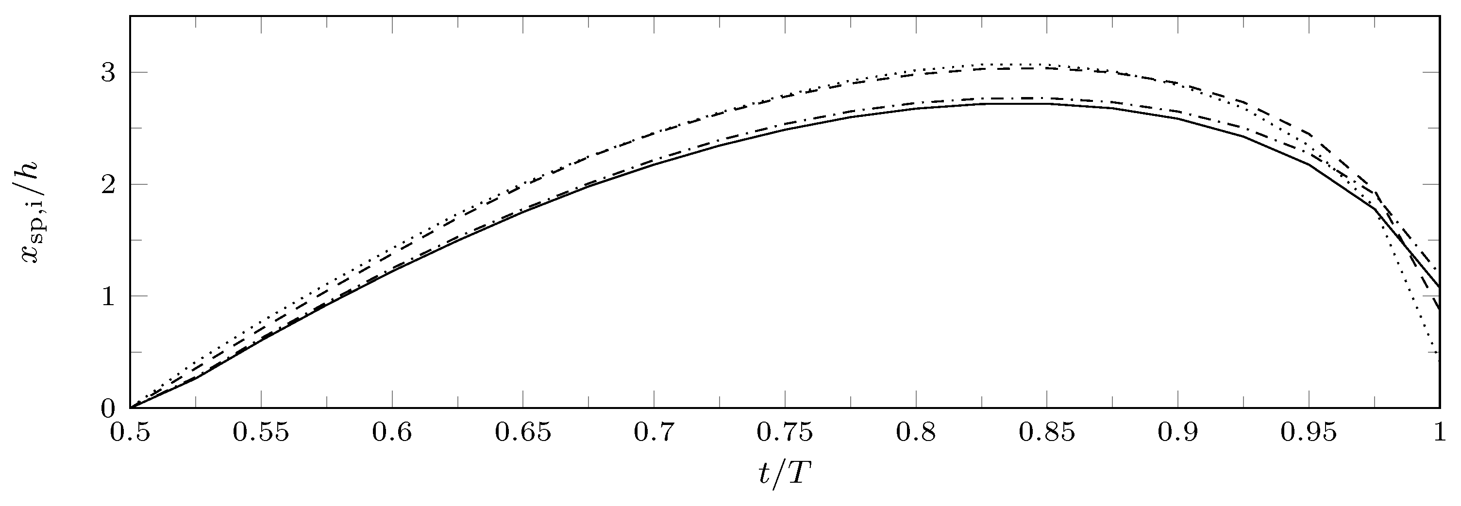
Finally, another important parameter of the external flow field of a synthetic jet issuing in an quiescent environment is the saddle point position. In this work the definition introduced by Zong & Kotsonis [41] is extended to a multi-slot configuration: for the i-th slot, the streamwise space-averaged velocity is evaluated as a function of x and t, using Equation (10)
then, for each phase, the position of the saddle point is determined as the station where . Of course, this definition makes sense only during the suction phase. The extremal position of the saddle point is a crucial parameter for an SJ actuator because it divides the near-field and the far-field regions of the jet. The variation of the saddle point position during the suction phase is shown in Figure 10 for different slots, to emphasize the differences between the external and the central slots. The saddle point for the external slots (1st and 12th) is closer to the exit plane due to edge effects, whereas there are no significant differences in the behavior of the other slots. The extremal position of the saddle points, however, is approximately 2.5–3 h for all the slots.
5. Conclusions
An experimental and numerical investigation of an innovative, multi-slot synthetic jet actuator has been carried out. The present slotted actuator is considered “innovative” from a constructive point of view, because it is composed of three diaphragms, acting on a single cavity, and linked to the external environment through four slots per diaphragm. Therefore, this configuration is novel with respect to other multi-slot devices which can be found in the specialized literature.
The experimental analysis has been performed collecting hot-wire measurements in the very-near-field of the jet, whereas the numerical investigation has been accomplished by means of incompressible DNS, using the open-source code OpenFOAM. The simulation has been validated against the experimental results, to ensure that the non-dimensional parameters of the simulation (Reynolds, Strouhal, Stokes numbers) have been correctly set.
The DNS computation has been used to give more insight to the potential effectiveness of the new device as a flow control system. The vortex visualization, obtained using iso-surfaces of the phase-averaged Q parameter, show that the vortex system is formed by twelve rectangular vortices, which quickly undergo secondary instability and transition to turbulence. The vortex development in the far field is characterized by the axis switching, as shown in previous works concerning rectangular jets. The characteristic length of the axis switching is related to the slot spanwise width, which is much smaller than the actuator spanwise length; this results in a vortex system which covers the entire spanwise length, which is an interesting feature for control purposes. In addition, the extension along the z direction of the vortex system is bounded by the slot spanwise length, which means that the actuator provides a localized modification of the flow to be controlled.
Finally, an investigation of the saddle point positions has been made for all the slots, showing that edge effects are of minor importance for the extreme position of the saddle point. Moreover, the saddle point position is relatively close to the exit plane, which means that the near-field region extends only for a few slot widths h from the exit plane. Further work is currently ongoing to extend both experimental and numerical investigations to the interaction field of the jet with the crossflow current.
Author Contributions
All the authors conceived and contributed equally to the writing of the manuscript.
Funding
The computational analysis was supported by a grant of HPC time from CINECA under the ISCRA project COSMOS. The experimental part of the work was granted by CIRA (Italian Center for Aerospace Research) under the SHAFT project.
Acknowledgments
The authors wish to thank Domenico Coiro for the use of the hot-wire equipment.
Conflicts of Interest
The authors declare no conflict of interest.
References
- Glezer, A.; Amitay, M. Synthetic jets. Annu. Rev. Fluid Mech. 2002, 34, 503–529. [Google Scholar] [CrossRef]
- Mohseni, K.; Mittal, R. Synthetic Jets: Fundamentals and Applications; CRC Press: Boca Raton, FL, USA, 2014. [Google Scholar]
- Cattafesta, L.N., III; Sheplak, M. Actuators for active flow control. Annu. Rev. Fluid Mech. 2011, 43, 247–272. [Google Scholar] [CrossRef]
- Smith, B.; Swift, G. A comparison between synthetic jets and continuous jets. Exp. Fluids 2003, 34, 467–472. [Google Scholar] [CrossRef]
- He, X.; Lustbader, J.A.; Arik, M.; Sharma, R. Heat transfer characteristics of impinging steady and synthetic jets over vertical flat surface. Int. J. Heat Mass Transf. 2015, 80, 825–834. [Google Scholar] [CrossRef] [Green Version]
- Smith, B.L.; Glezer, A. Jet vectoring using synthetic jets. J. Fluid Mech. 2002, 458, 1–34. [Google Scholar] [CrossRef] [Green Version]
- Tamburello, D.; Amitay, M. Active manipulation of a particle-laden jet. Int. J. Multiph. Flow 2008, 34, 829–851. [Google Scholar] [CrossRef]
- Chiatto, M.; Marchitto, L.; Valentino, G.; de Luca, L. Influence of piezo-driven synthetic jet on water spray behavior. At. Sprays 2017, 27, 691–706. [Google Scholar] [CrossRef]
- Dandois, J.; Garnier, E.; Sagaut, P. Numerical simulation of active separation control by a synthetic jet. J. Fluid Mech. 2007, 574, 25–58. [Google Scholar] [CrossRef]
- Amitay, M.; Smith, D.R.; Kibens, V.; Parekh, D.E.; Glezer, A. Aerodynamic flow control over an unconventional airfoil using synthetic jet actuators. AIAA J. 2001, 39, 361–370. [Google Scholar] [CrossRef]
- You, D.; Moin, P. Study of Flow Separation over an Airfoil With Synthetic Jet Control Using Large-Eddy Simulation; Technical Report; Annual Research Brief, Center for Turbulence Research: Stanford, CA, USA, 2007; pp. 311–321. [Google Scholar]
- Krishnan, G.; Mohseni, K. An experimental and analytical investigation of rectangular synthetic jets. J. Fluids Eng. 2009, 131, 121101. [Google Scholar] [CrossRef]
- Van Buren, T.; Amitay, M. Comparison between finite-span steady and synthetic jets issued into a quiescent fluid. Exp. Therm. Fluid Sci. 2016, 75, 16–24. [Google Scholar] [CrossRef]
- Girfoglio, M.; Greco, C.S.; Chiatto, M.; de Luca, L. Modelling of efficiency of synthetic jet actuators. Sens. Actuators A Phys. 2015, 233, 512–521. [Google Scholar] [CrossRef]
- McDonald, P.; Persoons, T. Numerical Characterisation of Active Drag and Lift Control for a Circular Cylinder in Cross-Flow. Appl. Sci. 2017, 7, 1166. [Google Scholar] [CrossRef]
- Crowther, W.J.; Gomes, L.T. An evaluation of the mass and power scaling of synthetic jet actuator flow control technology for civil transport aircraft applications. Proc. Inst. Mech. Eng. Part I J. Syst. Control Eng. 2008, 222, 357–372. [Google Scholar] [CrossRef]
- Mohamed, A.M.; Crowther, W.; Nabawy, M. Development of Valveless Resonant Micropumps for Liquid Applications. In Proceedings of the 2018 AIAA Aerospace Sciences Meeting, Kissimmee, FL, USA, 8–12 January 2018; p. 0580. [Google Scholar]
- Smith, B.L.; Glezer, A. The formation and evolution of synthetic jets. Phys. Fluids 1998, 10, 2281–2297. [Google Scholar] [CrossRef]
- Yao, C.; Chen, F.J.; Neuhart, D. Synthetic jet flowfield database for computational fluid dynamics validation. AIAA J. 2006, 44, 3153–3157. [Google Scholar] [CrossRef]
- Van Buren, T.; Whalen, E.; Amitay, M. Vortex formation of a finite-span synthetic jet: effect of rectangular orifice geometry. J. Fluid Mech. 2014, 745, 180–207. [Google Scholar] [CrossRef]
- Xia, X.; Mohseni, K. Transitional region of a round synthetic jet. Phys. Rev. Fluids 2018, 3, 011901. [Google Scholar] [CrossRef]
- Wang, L.; Feng, L.H.; Wang, J.J.; Li, T. Parameter influence on the evolution of low-aspect-ratio rectangular synthetic jets. J. Vis. 2018, 21, 105–115. [Google Scholar] [CrossRef]
- Kral, L.D.; Donovan, J.F.; Cain, A.B.; Cary, A.W. Numerical simulation of synthetic jet actuators. In Proceedings of the 4th Shear Flow Control Conference, Shear Flow Conference, Snowmass Village, CO, USA, 29 June–2 July 1997; p. 1824. [Google Scholar]
- Rizzetta, D.P.; Visbal, M.R.; Stanek, M.J. Numerical Investigation of Synthetic-Jet Flow Fields. AIAA J. 1999, 37, 919–927. [Google Scholar] [CrossRef]
- Kotapati, R.B.; Mittal, R.; Cattafesta, L.N., III. Numerical study of a transitional synthetic jet in quiescent external flow. J. Fluid Mech. 2007, 581, 287–321. [Google Scholar] [CrossRef]
- Gallas, Q.; Holman, R.; Nishida, T.; Carroll, B.; Sheplak, M.; Cattafesta, L. Lumped element modeling of piezoelectric-driven synthetic jet actuators. AIAA J. 2003, 41, 240–247. [Google Scholar] [CrossRef]
- Chiatto, M.; Capuano, F.; Coppola, G.; de Luca, L. LEM Characterization of Synthetic Jet Actuators Driven by Piezoelectric Element: A Review. Sensors 2017, 17, 1216. [Google Scholar] [CrossRef] [PubMed]
- Feero, M.A.; Lavoie, P.; Sullivan, P.E. Influence of cavity shape on synthetic jet performance. Sens. Actuators A Phys. 2015, 223, 1–10. [Google Scholar] [CrossRef] [Green Version]
- Kordík, J.; Trávníček, Z. Optimal diameter of nozzles of synthetic jet actuators based on electrodynamic transducers. Exp. Therm. Fluid Sci. 2017, 86, 281–294. [Google Scholar] [CrossRef]
- Chiatto, M.; Capuano, F.; de Luca, L. Numerical and experimental characterization of a double-orifice synthetic jet actuator. Meccanica 2018, 53, 2883–2896. [Google Scholar] [CrossRef]
- Sahni, O.; Wood, J.; Jansen, K.; Amitay, M. Three-dimensional interactions between a finite-span synthetic jet and a crossflow. J. Fluid Mech. 2011, 671, 254–287. [Google Scholar] [CrossRef]
- Jabbal, M.; Liddle, S.; Potts, J.; Crowther, W. Development of design methodology for synthetic jet actuator array for flow separation control applications. Proc. Inst. Mech. Eng. Part G J. Aerosp. Eng. 2013, 227, 110–124. [Google Scholar] [CrossRef]
- McGlynn, E.; Tran, S.; Sahni, O. Large Eddy Simulation of Flow Interactions of Segmented Synthetic Jets on an Airfoil. In Proceedings of the 47th AIAA Fluid Dynamics Conference, Denver, CO, USA, 5–9 June 2017; p. 3310. [Google Scholar]
- Invigorito, M.; Ceglia, G. SyntHetic Jet AcTuators for Flow Control (SHAFT), WP2 Progress Meeting; Technical Report; CIRA: Capua, Italy, 2016. [Google Scholar]
- Yavuzkurt, S. A guide to uncertainty analysis of hot-wire data. J. Fluids Eng. Trans. ASME 1984, 106, 181–186. [Google Scholar] [CrossRef]
- OpenFOAM and The OpenFOAM Foundation. Available online: http://www.openfoam.org (accessed on 27 July 2018).
- Palumbo, A.; Capuano, F.; de Luca, L. Performances of two open-source solvers in the numerical simulation of synthetic jets. In Proceedings of the 7th European Conference on Computational Fluid Dynamics (ECCM-ECFD 2018), Glasgow, UK, 11–15 June 2018. [Google Scholar]
- de Luca, L.; Girfoglio, M.; Chiatto, M.; Coppola, G. Scaling properties of resonant cavities driven by piezo-electric actuators. Sens. Actuators A Phys. 2016, 247, 465–474. [Google Scholar] [CrossRef]
- MARCONI, the New Tier-0 System. Available online: http://www.hpc.cineca.it/hardware/marconi (accessed on 27 July 2018).
- Hunt, J.C.; Wray, A.A.; Moin, P. Eddies, Streams, and Convergence Zones in Turbulent Flows; Technical Report CTR-S88; Center for Turbulence Research: Stanford, CA, USA, 1988. [Google Scholar]
- Zong, H.; Kotsonis, M. Formation, evolution and scaling of plasma synthetic jets. J. Fluid Mech. 2018, 837, 147–181. [Google Scholar] [CrossRef]
Figure 1.
(a) Actuator bottom part view; (b) Top part view.

Figure 2.
Reference frame and definition of the geometrical characteristics of the SJ actuator.

Figure 3.
Domain and boundary conditions used in the numerical simulations. Only half of the computational domain is represented in the sketch.
Figure 3.
Domain and boundary conditions used in the numerical simulations. Only half of the computational domain is represented in the sketch.
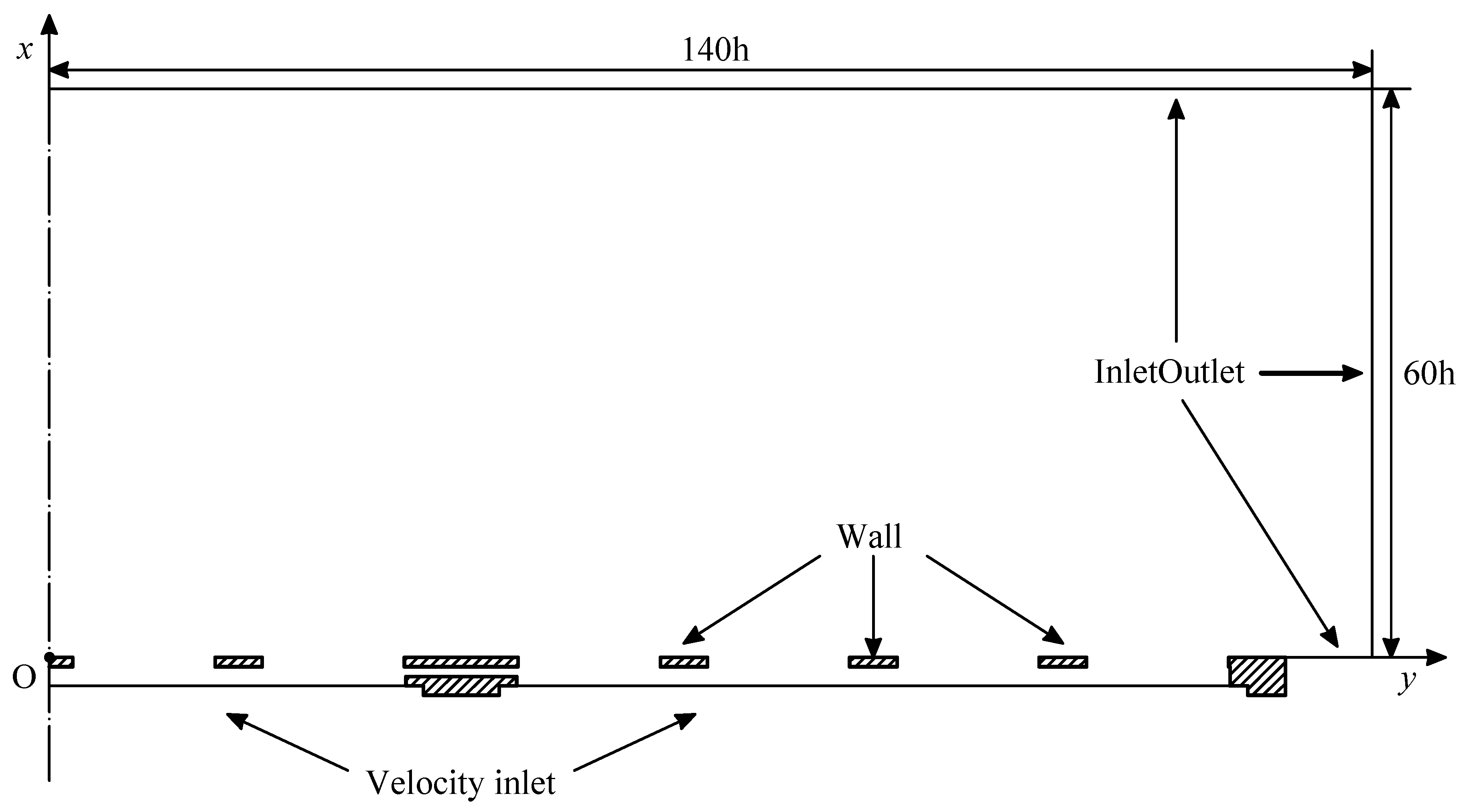
Figure 4.
Front (left) and side (right) view of the mesh used in the numerical simulation, zoomed near the slot exit plane.
Figure 4.
Front (left) and side (right) view of the mesh used in the numerical simulation, zoomed near the slot exit plane.

Figure 5.
Time history of the centerline phase-averaged streamwise velocity at the 2nd slot exit; numerical (solid line), experimental (•).
Figure 5.
Time history of the centerline phase-averaged streamwise velocity at the 2nd slot exit; numerical (solid line), experimental (•).

Figure 6.
Phase-averaged streamwise velocity profiles along the centreline, at increasing distances from the slot exit. Slot 2, (i) , (ii) , (iii) , (iv) , (v) , (vi) , (vii) , (viii) , (ix) , (x) ; numerical (solid line), experimental (•).
Figure 6.
Phase-averaged streamwise velocity profiles along the centreline, at increasing distances from the slot exit. Slot 2, (i) , (ii) , (iii) , (iv) , (v) , (vi) , (vii) , (viii) , (ix) , (x) ; numerical (solid line), experimental (•).
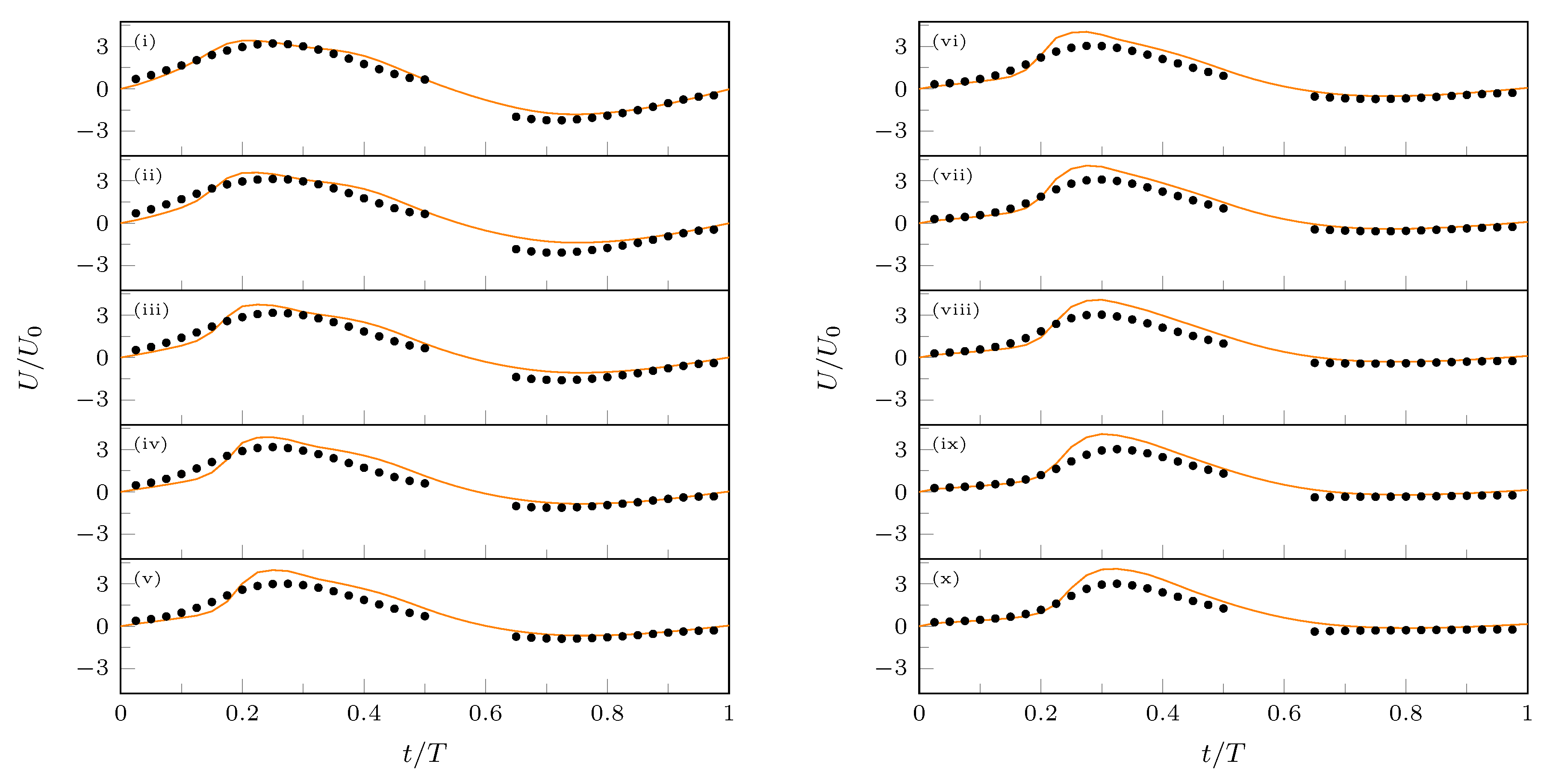
Figure 7.
Phase-averaged streamwise velocity profiles along the spanwise y direction; slot 2, . (a) Expulsion peak (); (b) Suction peak (); numerical (solid line), experimental (•).
Figure 7.
Phase-averaged streamwise velocity profiles along the spanwise y direction; slot 2, . (a) Expulsion peak (); (b) Suction peak (); numerical (solid line), experimental (•).

Figure 8.
Evolution of the vortical structures in the near-field for the central slots, visualized by isosurfaces. Ejection phase. The isosurfaces are colored with the phase-averaged streamwise velocity component .
Figure 8.
Evolution of the vortical structures in the near-field for the central slots, visualized by isosurfaces. Ejection phase. The isosurfaces are colored with the phase-averaged streamwise velocity component .
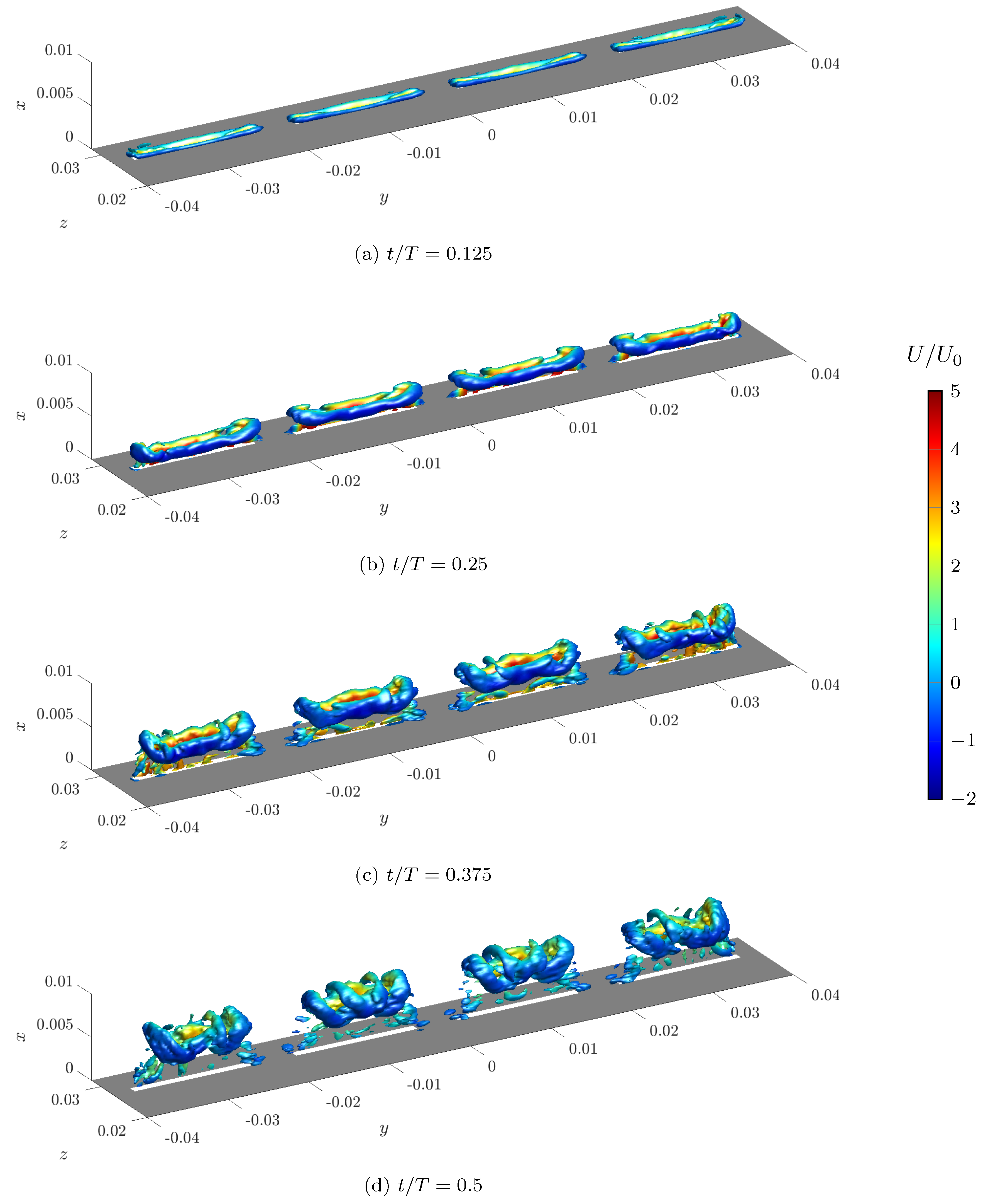
Figure 9.
Evolution of the vortical structures in the near-field for the central slots, visualized by isosurfaces. Suction phase. The isosurfaces are colored with the phase-averaged streamwise velocity component .
Figure 9.
Evolution of the vortical structures in the near-field for the central slots, visualized by isosurfaces. Suction phase. The isosurfaces are colored with the phase-averaged streamwise velocity component .
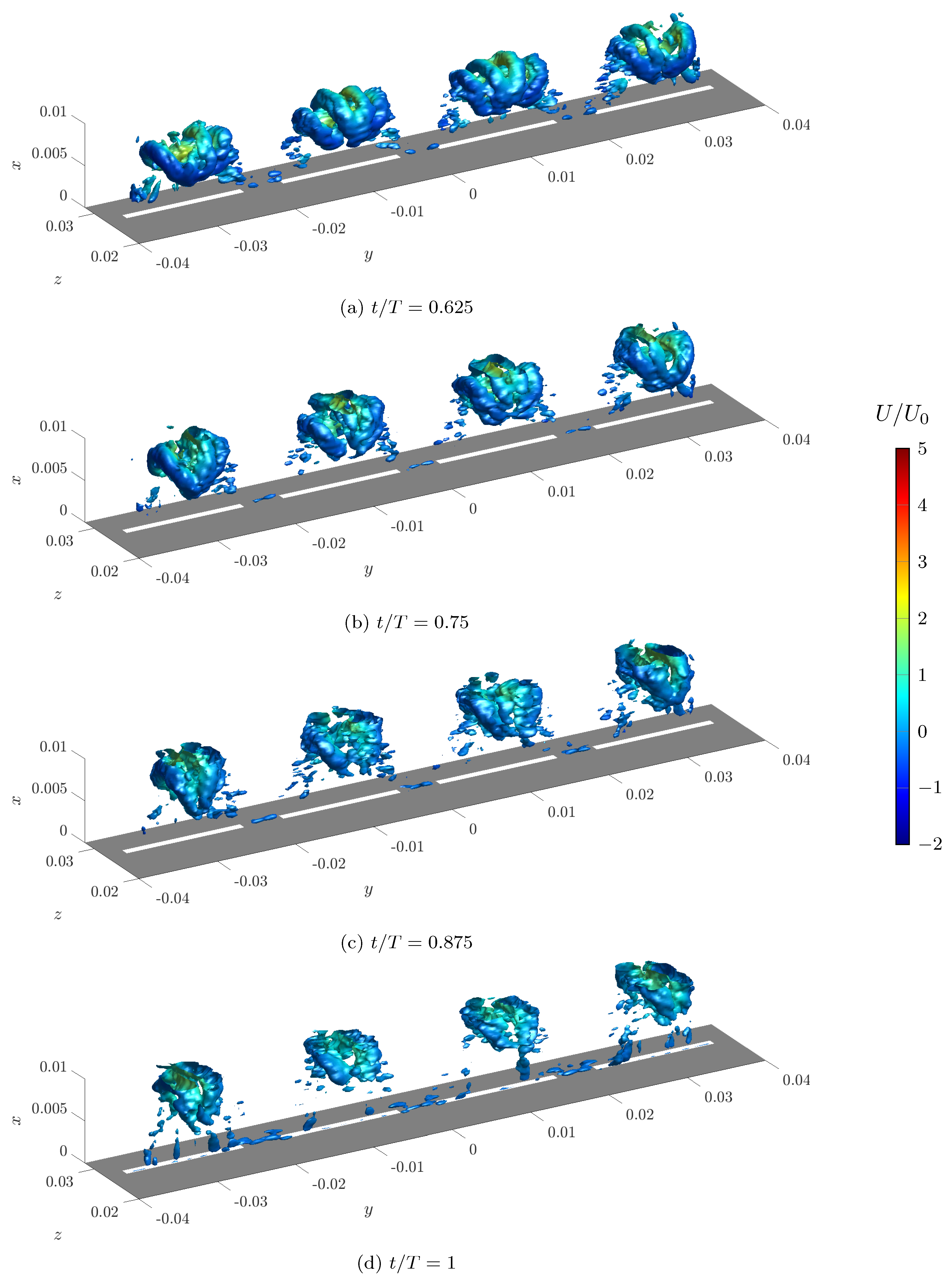
Figure 10.
Saddle point position , during the suction phase, for different slots: continuous and dotted lines refer to outer slots; dashed and dashdotted lines to inner slots.
Figure 10.
Saddle point position , during the suction phase, for different slots: continuous and dotted lines refer to outer slots; dashed and dashdotted lines to inner slots.


Table 1.
Main dimensional and non-dimensional parameters for the analyzed case.
| Parameter | Experimental | Numerical |
|---|---|---|
| Actuation frequency, f (Hz) | 250 | 250 |
| Slot width, h (mm) | 1 | 1 |
| Slot spanwise length, l (mm) | 15 | 15 |
| Average jet velocity, (m/s) | 2.85 | 2.95 |
| Maximum exit velocity, (m/s) | 9.1 | 9.5 |
| Reynolds number, | 190 | 197 |
| Strouhal number, | 0.0877 | 0.0842 |
| Stokes number, S | 10.23 | 10.23 |
| Dimensionless stroke length, | 11.41 | 11.86 |
© 2018 by the authors. Licensee MDPI, Basel, Switzerland. This article is an open access article distributed under the terms and conditions of the Creative Commons Attribution (CC BY) license (http://creativecommons.org/licenses/by/4.0/).
Share and Cite
MDPI and ACS Style
Palumbo, A.; Chiatto, M.; De Luca, L. Measurements versus Numerical Simulations for Slotted Synthetic Jet Actuator. Actuators 2018, 7, 59. https://doi.org/10.3390/act7030059
AMA Style
Palumbo A, Chiatto M, De Luca L. Measurements versus Numerical Simulations for Slotted Synthetic Jet Actuator. Actuators. 2018; 7(3):59. https://doi.org/10.3390/act7030059
Chicago/Turabian StylePalumbo, Andrea, Matteo Chiatto, and Luigi De Luca. 2018. "Measurements versus Numerical Simulations for Slotted Synthetic Jet Actuator" Actuators 7, no. 3: 59. https://doi.org/10.3390/act7030059
Note that from the first issue of 2016, this journal uses article numbers instead of page numbers. See further details here.