Modelling of a Partially Loaded Road Tanker during a Braking-in-a-Turn Maneuver

1
Federal Institute for Materials Research and Testing (BAM), 12203 Berlin, Germany
2
Instituto Politécnico Nacional, CICATA-Querétaro, Querétaro 76090, Mexico
*
Author to whom correspondence should be addressed.
Actuators 2018, 7(3), 45; https://doi.org/10.3390/act7030045
Submission received: 27 June 2018
/
Revised: 25 July 2018
/
Accepted: 1 August 2018
/
Published: 1 August 2018
(This article belongs to the Special Issue Novel Braking Control Systems)
Abstract
:Road safety depends on several factors associated with the vehicle, to the infrastructure, as well as to the environment and experience of vehicle drivers. Concerning the vehicle factors influencing the safety level of an infrastructure, it has been shown that the dynamic interaction between the carried liquid cargo and the vehicle influences the operational safety limits of the vehicle. A combination of vehicle and infrastructure factors converge when a vehicle carrying liquid cargo at a partial fill level performs a braking maneuver along a curved road segment. Such a maneuver involves both longitudinal and lateral load transfers that potentially affect both the braking efficiency and the lateral stability of the vehicle. In this paper, a series of models are set together to simulate the effects of a sloshing cargo on the braking efficiency and load transfer rate of a partially filled road tanker. The model assumes the superposition of the roll and pitch independent responses, while the vehicle is equipped with Anti-lock braking System brakes (ABS) in the four wheels. Results suggest that cargo sloshing can affect the performance of the vehicle on the order of 2% to 9%, as a function of the performance measure considered. A dedicated ABS system could be considered to cope with such diminished performance.
1. Introduction
Cargo shifting during braking, characterized by changes in the position of cargo’s center of gravity within the vehicle, is an undesirable phenomenon when analyzing the performance of vehicle braking systems, as such phenomenon originates longitudinal load transfers that affect the magnitude of the tire-pavement normal forces, which are the main source for vehicle braking. Such variations in the value of these vertical forces increase the probability that the unloaded wheels lock-up, leading to a reduction in the values of the available braking forces. In the case of straight line braking, several studies have been reported in the literature about the longitudinal load transfer that takes place [1,2]. When performing braking-in-a-turn maneuvers (BIT), the load transfer amongst the vehicle wheels is higher, as both longitudinal and lateral load transfer simultaneously occur, further affecting the directional stability of the vehicle, which can oversteer due to a diminished tire-pavement friction due to lock-up wheels. While such load transfer occurs even if no cargo shifting occurs, the phenomenon of load transfer could be greater if the vehicle is loaded with liquid cargo at partial fill levels. In this case, when the liquid cargo moves within its container on the vehicle, the center of gravity of the cargo moves both laterally and vertically, thus affecting the load distribution on the wheels and the braking efficiency of the vehicle. The probability of a wheel to lock-up, when the vehicle performs a braking-in-a-turn maneuver, should thus be higher when the vehicle is a road tanker traveling at partial fill levels. According to simulations results, the sloshing of the cargo causes an increase of 42% in the longitudinal-lateral load transfer when a half-filled road tanker performs a 3.5 m/s2 braking-in-a-turn maneuver along a 500-m radius curve [3]. Such increased load transfer thus implies a greater probability for the wheels to lock-up.
Complexities associated with modeling of the liquid cargo–vehicle interaction during a braking-in-a-turn-maneuver has been recognized, due to the coupled cargo–vehicle dynamics [4].
The effect of baffles on the forces and moments derived from sloshing, when the vehicle performs a braking-in-a-turn maneuver, is reported in [5] on the basis of a boundary finite element model that is used to characterize the forced response of an elliptical tank to perturbations both in longitudinal and lateral direction, particularly, ramp-step input accelerations. That is, such a model does not integrate the whole vehicle dynamics.
A quasi-static model was proposed by Kang et al. to study the behavior of an articulated road tanker when subjected to a braking-in-a-turn maneuver [6]. With such approach, the authors report an increased probability of such a vehicle to roll over as a result of the longitudinal and lateral shifting of the center of gravity of the cargo. However, such quasi-static analyses have been exhibited as limited and insufficient to characterize the behavior of the road tankers when performing such types of maneuvers, as such quasi-static methods do not take into account the dynamics of the cargo [5].
Braking-in-a-turn maneuvers have been recognized as challenging maneuvers that demands from the vehicle high levels of lateral and directional stability [7]. In the case of straight braking maneuvers, Otremba et al. [8] report the validation of a simplified approach to simulate the pressure developed within two pressure-sensor-instrumented chambers in a road semitrailer. The simulation results compare well with the experiment outputs. Such a model has been expanded in this paper to consider both the roll and the pitch response of the vehicle.
In view of what has been described above, there is not an integral approach for studying the behavior of the road tankers when subjected to braking-in-a-turn-maneuvers, and this applies for both experimental and theoretical approaches.
In this paper, several theoretical and validated models are set together to study the liquid cargo–vehicle interaction when the vehicle is a road tanker that is partially filled and performs a braking-in-a-turn maneuver. While the validated models refer to the free sloshing frequency of the liquid inside the tank, the theoretical models refer to the dynamic liquid cargo–vehicle interaction, as it is described in the model section of the paper. The analysis is based upon the superposition of the longitudinal and lateral responses of the vehicle, in order to estimate the forces at each of the four vehicle’s wheels. The vehicle is equipped with an Antilock Brake System (ABS) in each wheel. The purpose of this paper is to illustrate the needs for an improved ABS technology that considers such greater load transfer conditions.
2. Model Description
Different assumptions are made for the development of the models, as follows:
- Independent dynamics for the roll and pitch motions of the vehicle. Justification for this derives from highly different mechanical properties for the sloshing cargo in these two directions. That is, the longitudinal dimension of the vehicle is several times its lateral dimension. While the assumption of a null cross-coupling between the lateral and longitudinal vibration modes of the vehicles has been adopted previously [9,10], we consider it necessary to experimentally validate such an approach in the case of a sloshing cargo.
- A mechanical pendulum describes the sloshing cargo main mode of vibration. Justification for this is the force involved in the braking maneuver, which excites the first mode of vibration of the liquid, while a validated methodology is used to set the properties of the respective pendulum analogies.
- A sufficiently high tire–pavement friction coefficient and normal forces avoids any consideration for the yaw instability of the vehicle, which is justified in the light of a dry pavement [6].
- The model does not take into account the axle dynamics, as the vehicle is equipped with independent suspension for each wheel, and the pavement is perfectly flat.
2.1. Multibody Simplified Sloshing Model
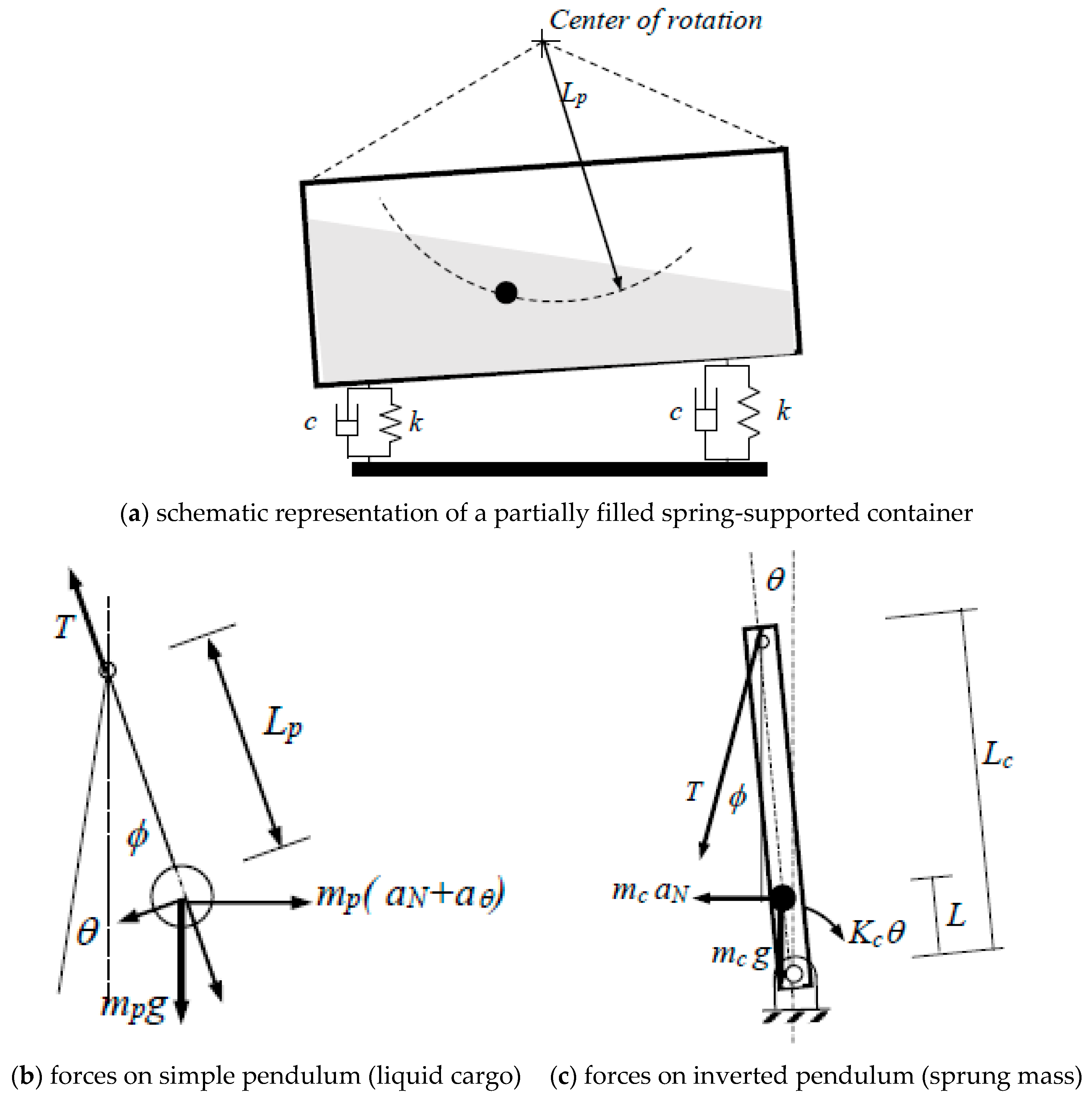
Figure 1a describes a partially filled container supported on springs. Figure 1b,c describe the corresponding models, consisting of a simple pendulum and an inverted pendulum. While the simple pendulum describes the sloshing cargo, the inverted pendulum describes the spring-supported chassis.
As it can be observed in this figure, the interaction between the simple pendulum representing the sloshing cargo, and the chassis, is given through the tension developed in the pendulum string. That is, a full mechanical system is used to represent the dynamic interaction between the cargo and the chassis. For the diagrams in Figure 1, the equations of motion are derived, as follows:
where the tension in the string is calculated in terms of the radial and tangential accelerations, as follows:
An equivalent torsional stiffness is calculated to describe the suspension system of the vehicle, for both the longitudinal and the lateral response model. For a left (front) and right (rear) suspension situation, with different lengths from the center of gravity to the respective end, the equations for the equivalent torsional stiffness K and damping C read as follows:
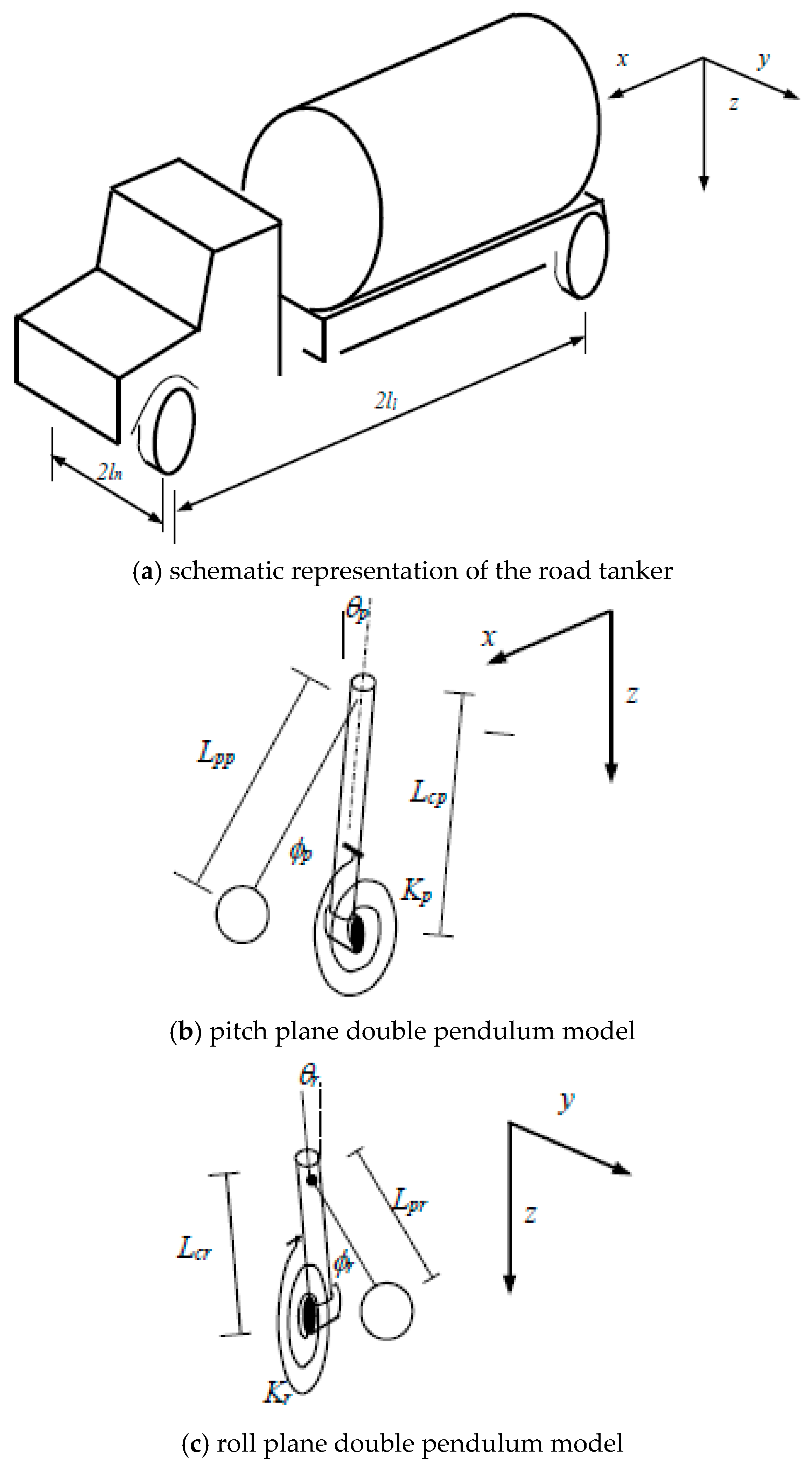
where k represents an equivalent stiffness for the left (front) (l) and right (rear) (r) ends of the vehicle, and l represents the distance from the center of gravity to the respective position of the suspension. The stiffness and damping values on each end of the vehicle were obtained as the summation of the respective individual suspension properties of such end. The same criterion was used in the case of the damping properties of the suspension, in order to obtain C as a function of the equivalent viscous damping on the ends of the vehicle (c). Two models as the one described in Figure 1 were considered independently to simulate the roll and pitch responses of a straight road tanker. Figure 2 illustrates such models to represent the roll and pitch motions of the vehicle.
The force at the suspension position is thus given by the following expression:
where r and s refer to the position of the suspension, r can be rear or front, and s can be left or right; k refers to the respective suspension stiffness, while c the corresponding damping; and refer to the chassis roll and pitch angles, respectively; lengths l refer to the track and wheelbase of the vehicle (Figure 2a).
The mechanical characteristics of the pendulum, as far as its length is concerned, are based in this paper on a validated formulation related to gravity waves. While the original formulation concerned rectangular containers [11], it was later validated that the formulation was still valid for non-rectangular cross-sections, if an equivalent rectangular section is obtained from the non-rectangular cross section [12]. That is, an equivalent height for the fill level, according to the following equation [11]:
where cw is the wave speed, L is the length of the free surface, κ is the wave number, and h is the equivalent profundity of the resultant equivalent cross section. In this equation, f is the natural frequency of the wave vibration and g is the gravity acceleration. The free surface dimensions and the resulting pendulum lengths for the simulated road tanker are listed in Table 1.
2.2. ABS System
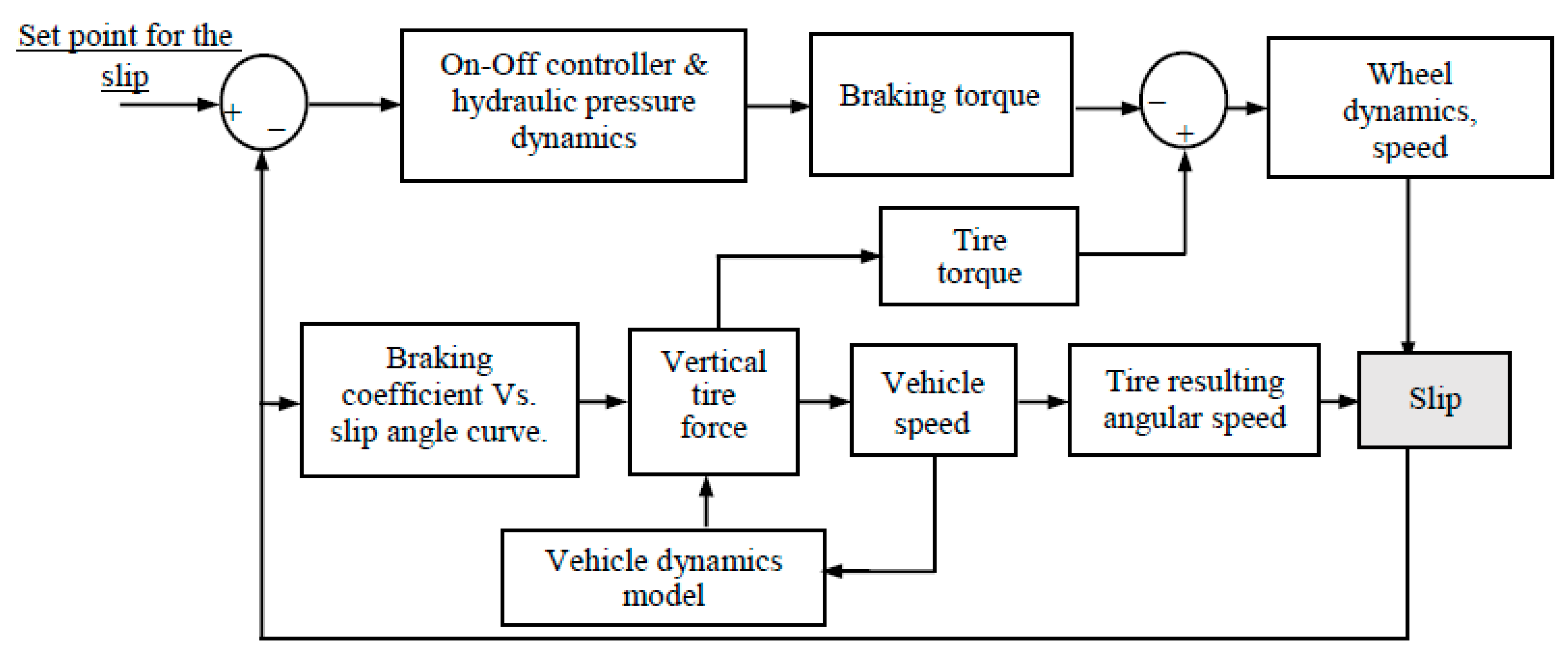
The ABS system considered for each of the wheels located at the suspension position of the vehicle consists of a bang-bang (on/off) controller that is set to a certain level of slip in order to get the maximum braking coefficient. The maximum braking coefficient is assumed as 0.55 for a dry pavement. Figure 3 describes the functional blocks that integrate the ABS system. In general terms, the torque difference between the braking torque and the one derived from the friction at the tires are considered to calculate the wheel slip and the corresponding braking coefficient, in order to determine the available braking force, in terms of an assumed slip angle–braking coefficient relationship [13].
The normal force for the calculation of the braking force is obtained from the dynamics of the roll and pitch vibration of the vehicle.
3. Results
The simulation results are now presented in different parts. First, the time free response of the sloshing cargo response is described, and then a parametric analysis is carried out of the different factors influencing the lateral and longitudinal performance of the vehicle, including the effect of vehicle’s initial speed and the radius of curvature of the road. The properties of the vehicle and the ABS system incorporated in each of the suspension positions are listed in Table 1. As it can be observed in this table, the non-sloshing condition of the cargo has been assumed through an increased damping. The vehicle is considered to travel at a partial fill level of 50%.
3.1. Performance Measure
Two performance measures are considered to assess the effect of cargo sloshing on the dynamic behavior of the vehicle while performing a braking-in-a-turn maneuver. On the one hand, the braking distance is considered, and, on the other hand, it is considered the maximum load transfer obtained amongst the different suspension positions, , according to the following expression [14]:
where and are the forces on the left and right sides of the vehicle.
3.2. Free Responses to Initial Angular Perturbation
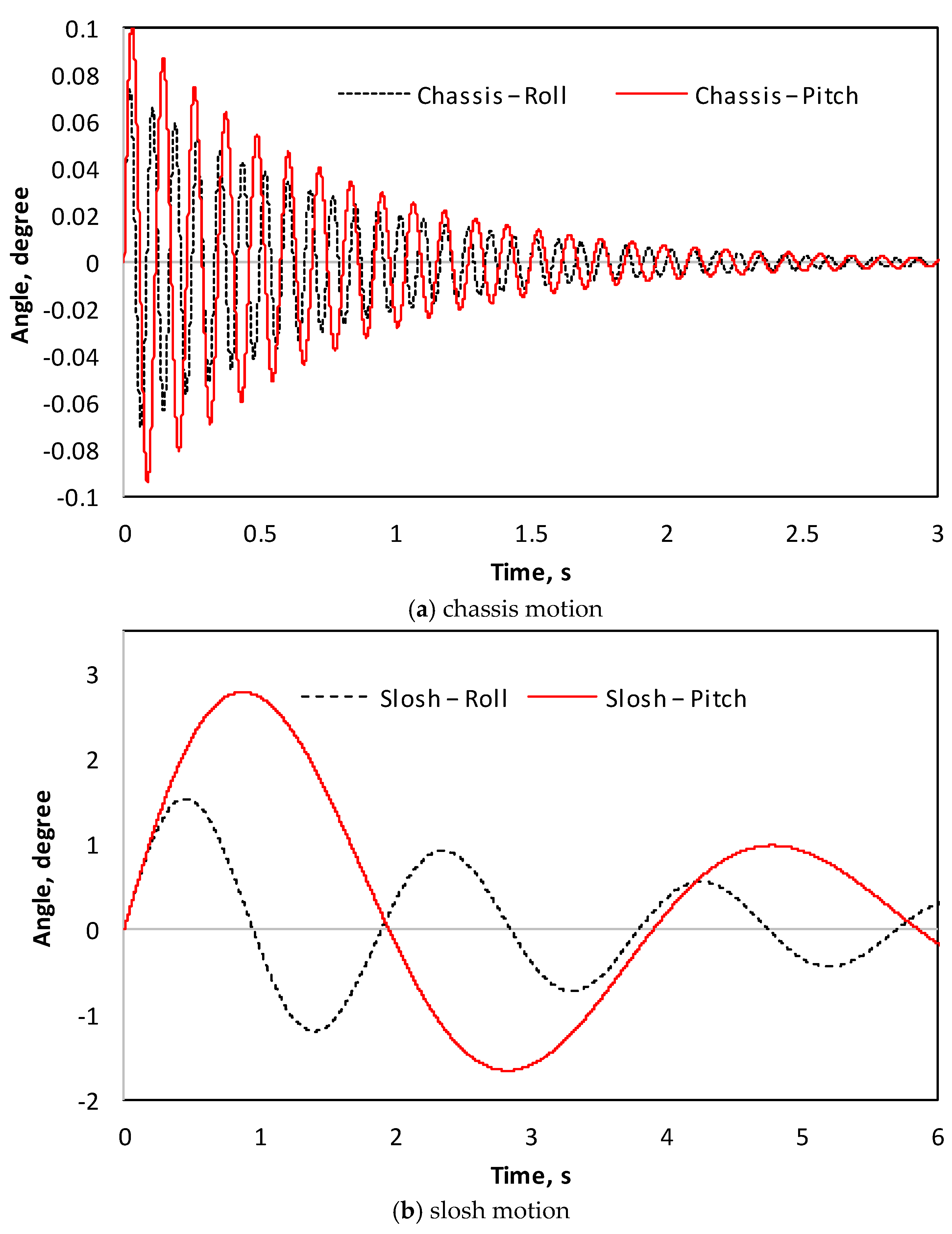
Figure 4a,b illustrate the free response of the chassis and the sloshing cargo to an initial angular speed given to these degrees of freedom, for the pitch and roll motions, respectively. According to these results, the sloshing and the chassis exhibit their specific natural frequencies, where the minimum natural frequency is observed in the case of the pitch motion of the chassis, while the maximum frequency is observed in the case of the roll motions of the chassis. A moderate level of damping is further observed in these results.
3.3. Time Responses
To illustrate the dynamics of the systems and the effect of the sloshing cargo on the performance of the vehicle, Figure 5, Figure 6 and Figure 7 describe the time histories of several simulation outputs. The simulation conditions for these results are: 80 km/h as an initial speed, and a road radius of 200 m.
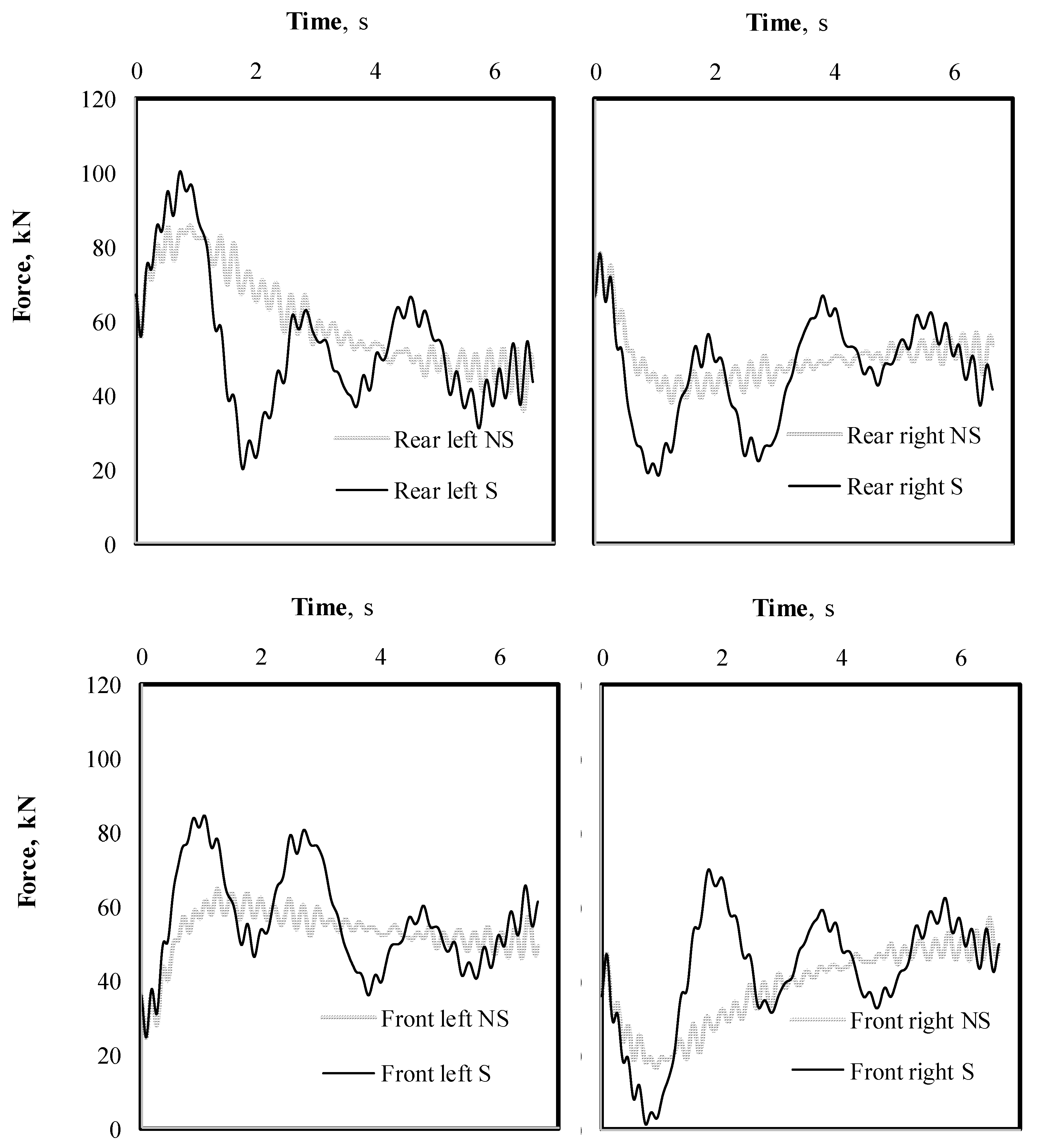
In general, it can be observed in these results, a small effect of the sloshing condition on the overall behavior of the different outputs from the model. However, the more significant variation is observed in the case of the normal force available for braking (Figure 5), where the sloshing condition represents, approximately, an oscillation about the non-sloshing condition. In this respect, two ranges of frequencies are observed, which are attributable to the high frequency of the roll chassis motion, and the low frequency of the sloshing motion.
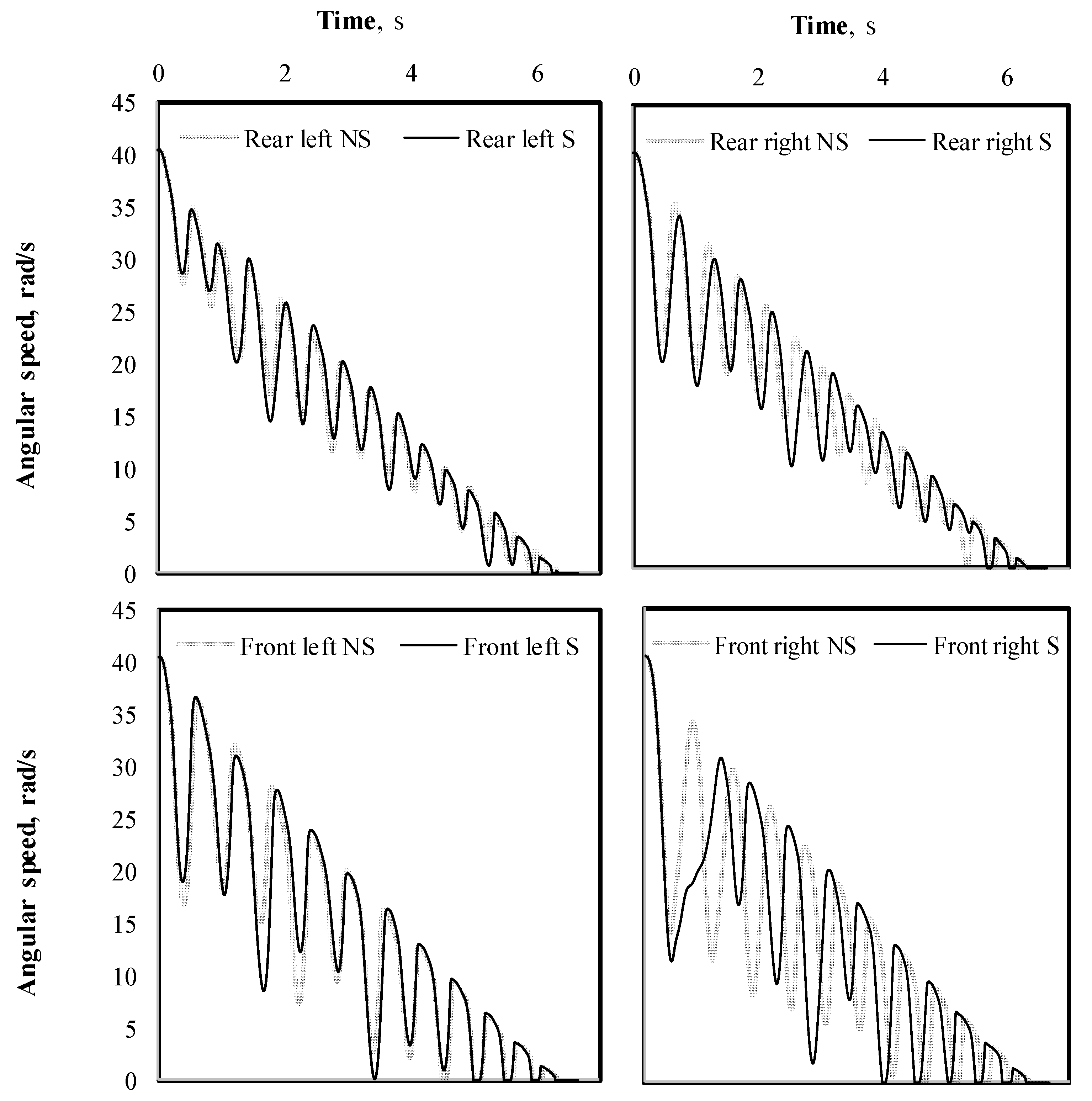
Figure 6 illustrate the time variation of the wheel angular speed for the different suspension positions and cargo condition. In this case, the effect of the sloshing cargo is marginal, with only small differences in the case of the rear wheels. In general terms, the wheel speed variations are attributed to the ABS operating algorithm (Figure 3).
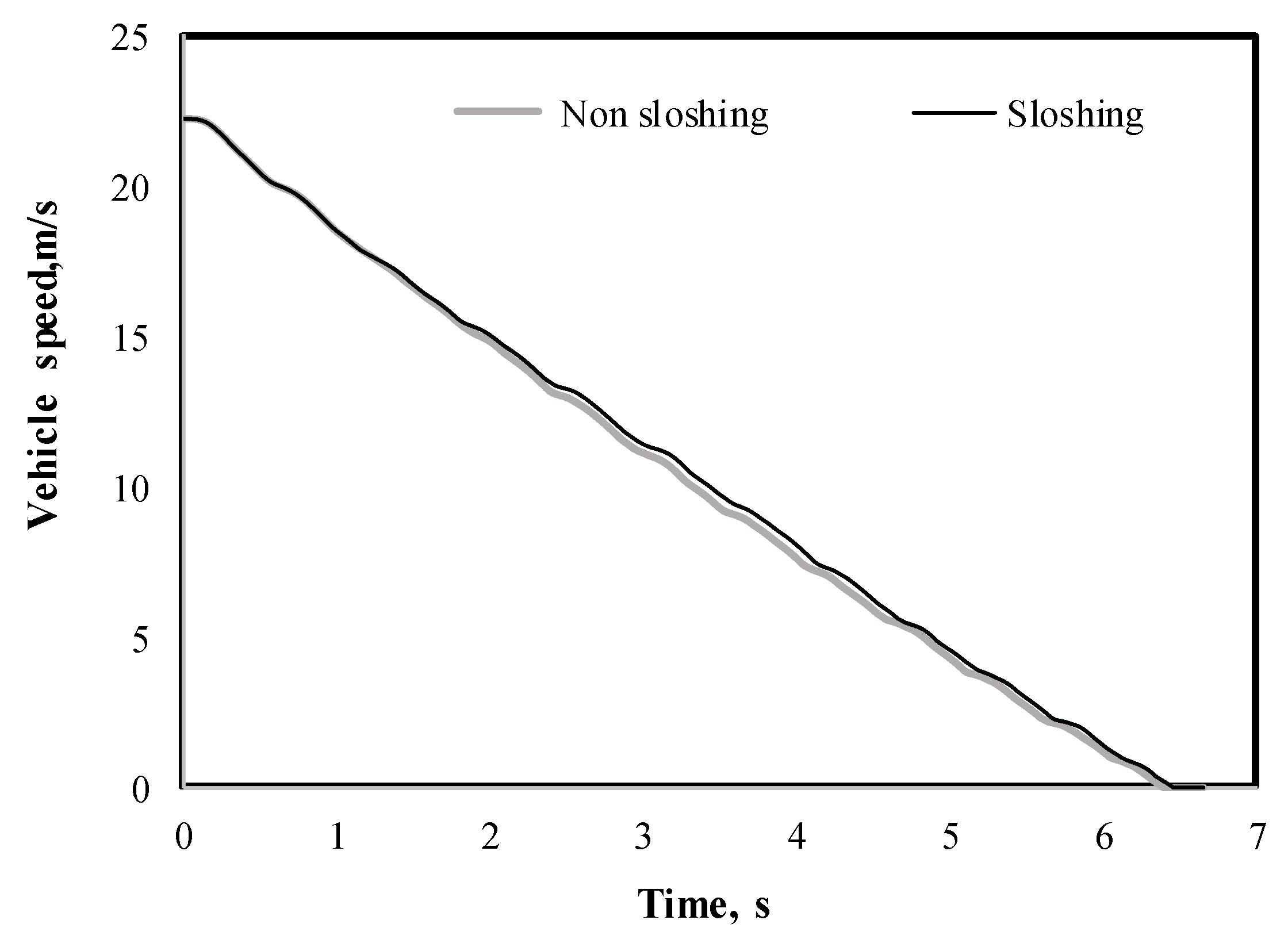
Figure 7 illustrates the corresponding braking results for the vehicle speed. In this case, the effect of the sloshing cargo on the braking time is also marginal, as in the case of the rotational dynamics of the wheels (Figure 6). The oscillations of the speed are attributed to the operation of the ABS system. It can be observed that, in this domain, the stopping maneuver in the case of the sloshing cargo will be only a few fractions of a second longer than in the case of the non-sloshing cargo.
3.4. Parametric Analysis
A parametric analysis is presented to observe the effect of cargo condition on the performance of the vehicle regarding its braking distance and the maximum load transfer.
3.4.1. Braking Distance
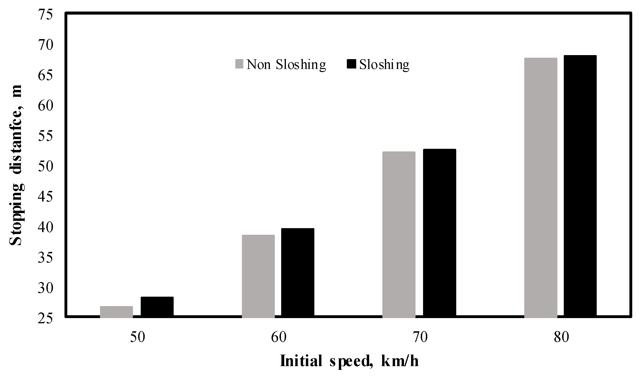
Figure 8 illustrates the effect of the initial speed on the braking distance of the vehicle, in the case of a 200-m road radius, where the maximum sloshing effect is observed at 50 km/h and 1.38 m longer. It can be observed further in these results that the effect of the initial speed follows an approximate linear variation.
Figure 9 summarizes the effect of the sloshing cargo on the braking distance, as a percentage of the values obtained for the non-sloshing cargo situation, for different curvature radius of the road, where the maximum effect is observed around 5, regardless of the curvature radius. It should be noted that, for speed higher than 50 km/h, the sloshing cargo caused the right tires to lose contact with the pavement.
On the other hand, it can be observed also in Figure 9 that the effect of the sloshing cargo decreases with the initial speed, with a minimum effect of 5.49% (radius = 200; speed = 50 km/h). It should be noted that the average effect of the sloshing cargo on the braking distance of the vehicle results as 3.21%.
3.4.2. Maximum Load Transfer
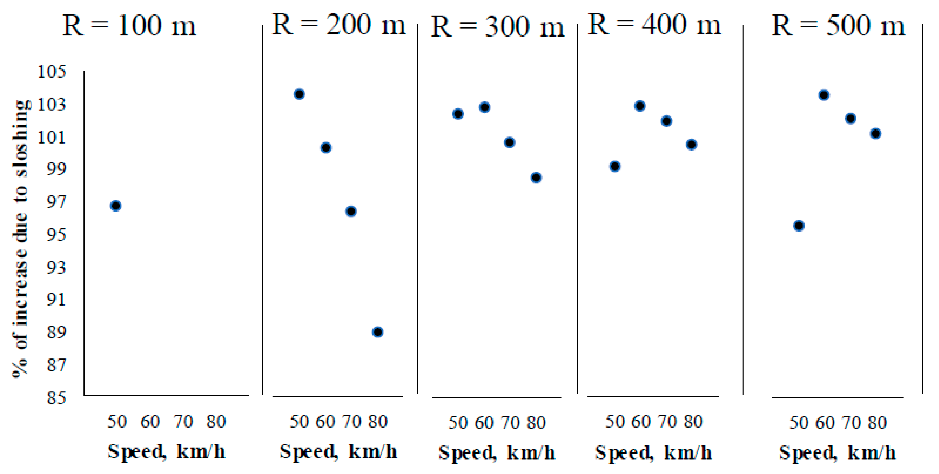
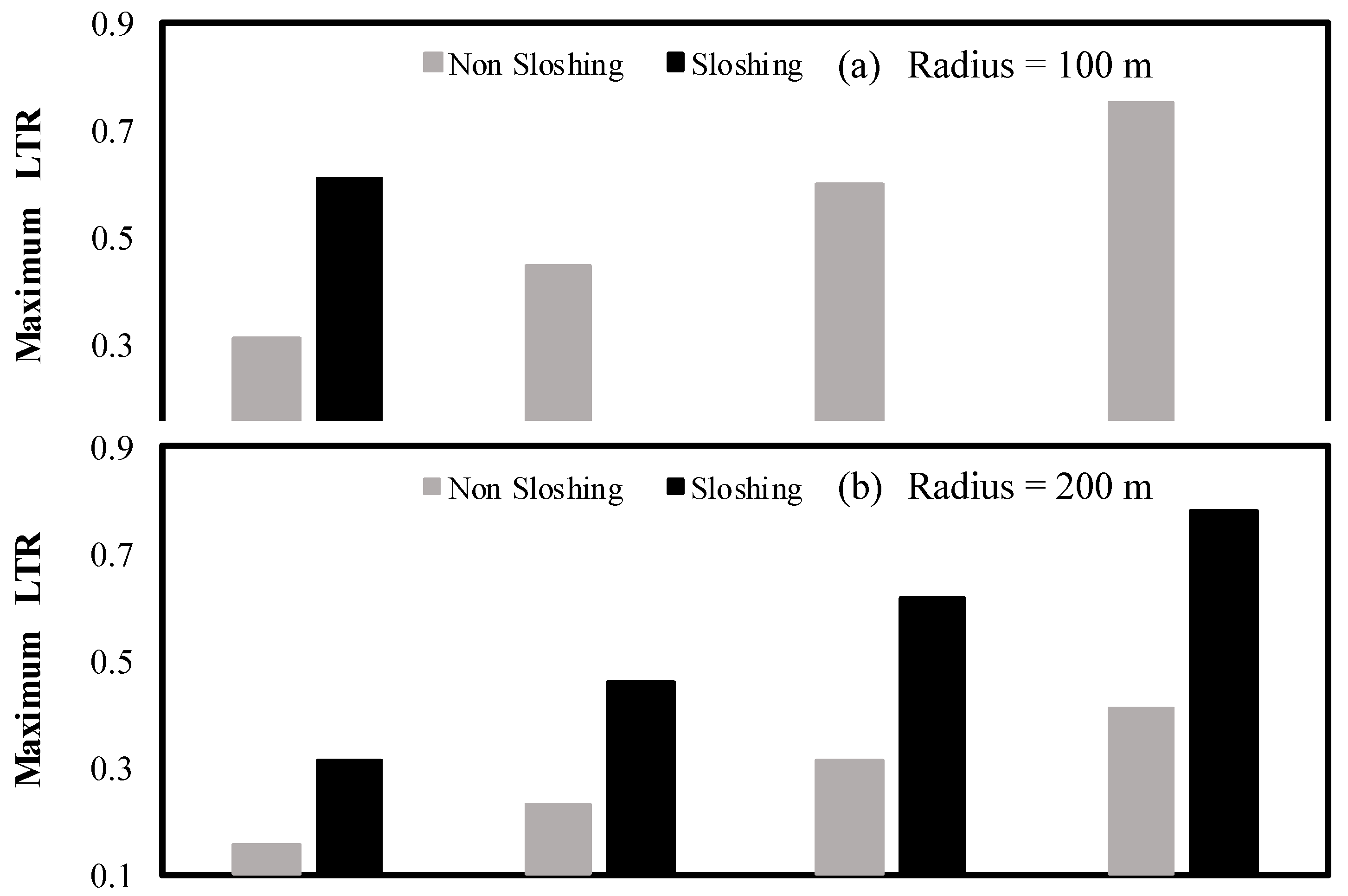
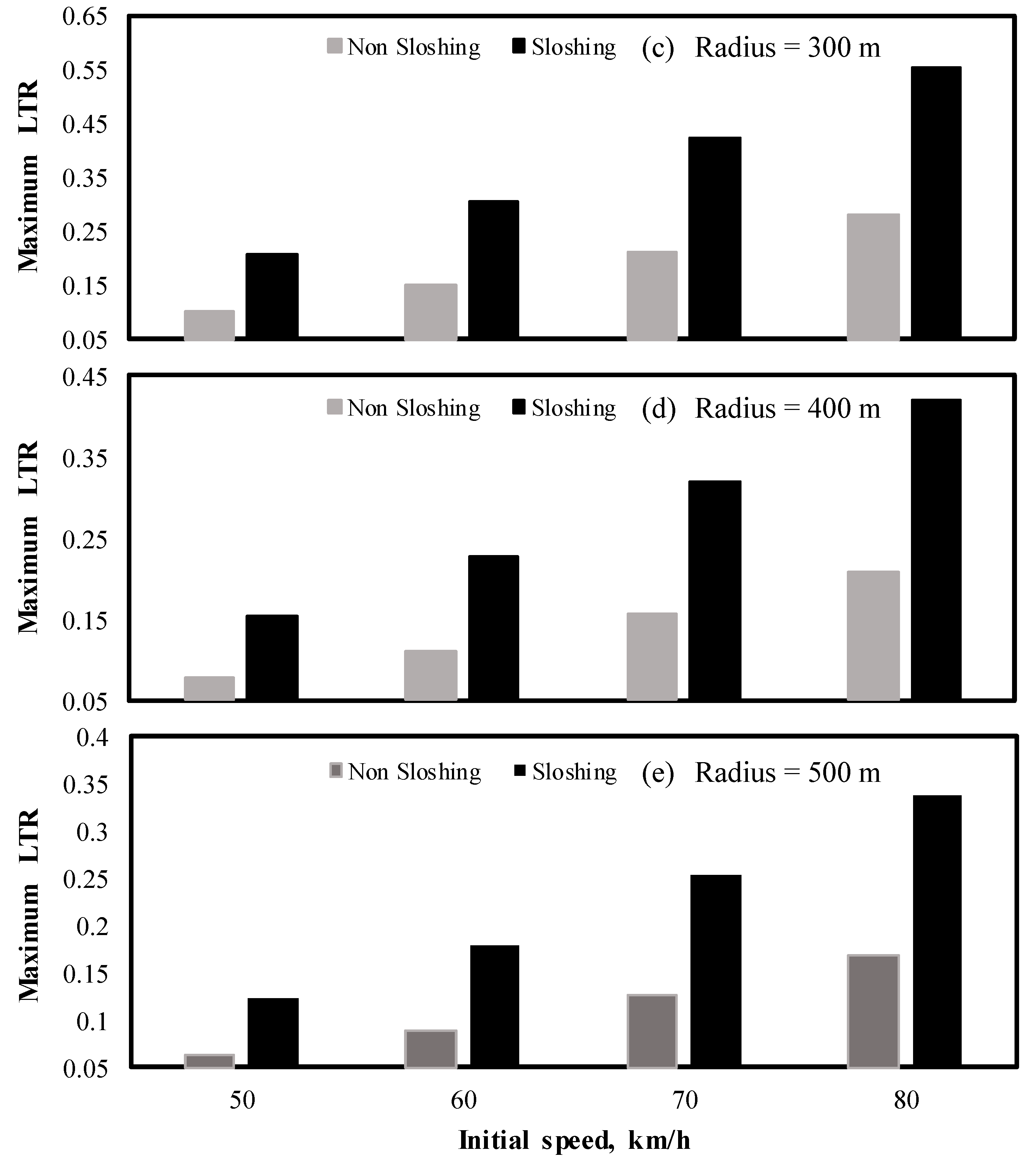
Figure 10 illustrates the effect of the initial speed and turning radius on the maximum load transfer ratio, as defined by Equation (7). In this case, a relatively significant effect of the sloshing cargo on the maximum load transfer ratio can be observed. In general, the maximum load transfer increases with the initial speed.
It should be noted that the values of the load transfer in Figure 10 are not within a safety margin, that is, the maximum value attainable is 1, which means a potential rollover condition. The maximum value in these results is 0.77, for the combination of short turning radius (200 m) and maximum speed.
Figure 11 summarizes the effect of cargo sloshing on the maximum load transfer, with a percentage increase ranging from 89% to 104%. The average effect for the full set of results being 100%. In this regard, the relatively minor effects at the low speed condition are attributed to a combination of influential factors, including the shorter braking time and the superposition of sloshing vibrations.
4. Discussion
The magnitude of the effect of cargo sloshing on the vehicle performance has been found to be a function of the performance measure considered. In this respect, while the braking distance is only slightly affected by the sloshing cargo, 3.21% as an average; the maximum load transfer is affected by 100% as an average. In analyzing these results, it should be taken into account that such small averages make the difference between having a crash or not. That is, 3.21% difference during a braking maneuver can represent 1.6 m when the braking distance is 50 m. In this respect, such small effect of the cargo sloshing for the braking distance could be attributable to the fact that, while some wheels become un-loaded due to the load transfer, other wheels become over-loaded, in such a way that the overall variation of the normal forces involved in the calculation of the load transfer becomes small.
On the other hand, an increase of more than 85% in the load transfer can represent a rollover situation. In this respect, it should be noted that such significant difference in performance between braking distance and lateral stability, derives from the fact that the lateral stability depends on the instantaneous values of the associated forces, while the braking distance represents an accumulated effect. As it can be observed in Figure 5, the sloshing causes strong variations in the forces. However, the average values are not significantly different. The difference in the average force values for the results in such figure is 8.51%.
The situation described in this paper points out towards a challenging situation for the efficiency of any antilock brake system. This situation can be observed when considering the wheel speed results where the sloshing is causing the wheels to unlock. In this respect, the use of baffles, both in the longitudinal and lateral direction, could contribute a diminishing of the lateral load transfer. However, the use of longitudinal baffles is limited.
It should be noted that the average value of 3.21% for the effect of the sloshing cargo on the braking distance is subjected to uncertainties derived from the parameters considered in this paper. In this respect, different operational conditions can shift the results upwards or downwards. For example, the pavement profile is a parameter assumed in this model, which could imply a shift in the results. Other influential operational conditions would involve some ABS system characteristics, such as the temperature of the braking fluid or the friction available at the braking pads.
5. Conclusions
This paper describes a theoretical model to simulate the effects of a sloshing cargo on the safety performance of a vehicle that performs a braking-in-a-turn maneuver when travels at a partial fill level. The fundamental assumption of the model consists of the superposition of the effects of two simplified mechanical-analogy models that represent a liquid cargo on a vehicle, including one for the roll motion and another one for the pitch motion. The distinctive characteristics of the mechanical models, however, is that they are based upon a validated formulation to establish the properties of the pendulum (length).
The results suggest a small effect of the sloshing cargo on the braking efficiency of the cargo, while the load transfer is moderately affected. However, such results should be put into a perspective, according to which such small variations can represent the avoidance of a rear-end crash or a rollover. In this respect, a specialized ABS system could be considered to improve the performance of such kind of vehicles when performing such maneuvers.
Validation of the proposed methodology should be performed as a continuation of this research effort.
Author Contributions
F.O. and J.A.R.N. conceived of the present idea. A.A.L.G. and J.A.R.N. developed the theory and carried out the computations. F.O. verified the analytical methods and supervised the findings of this work.
Funding
This research received no external funding.
Conflicts of Interest
The authors declare no conflict of interest.
References
- Yan, G.; Rakheja, S. Straight-line braking dynamic analysis of a partly-filled baffled and unbaffled tank truck. Proc. Inst. Mech. Eng. Part D J. Automob. Eng. 2009, 223, 11–26. [Google Scholar] [CrossRef]
- Biglarbegian, M.; Zu, J.W. Tractor—Semitrailer model for vehicles carrying liquids. Veh. Syst. Dyn. 2007, 44, 871–885. [Google Scholar] [CrossRef]
- Romero, J.A.; Otremba, F.; Lozano-Guzmán, A.A. Simulation of liquid-cargo–vehicle interaction under lateral and longitudinal accelerations. In Proceedings of the 9th International Conference on Computational Methods, Rome, Italy, 6–10 August 2018. [Google Scholar]
- Ibrahim, R.A.; Singh, B. Assessment of ground vehicles tankers interacting with liquid sloshing dynamics. Int. J. Heavy Veh. Syst. 2018, 25, 23–112. [Google Scholar] [CrossRef]
- Kolaei, A. Dynamic Liquid Slosh in Moving Containers. Ph.D. Thesis, Department of Mechanical and Industrial Engineering, Concordia University, Montreal, QC, Canada, 2014. [Google Scholar]
- Kang, X.; Rakheja, S.; Stiharu, I. Cargo load shift and its influence on tank vehicle dynamics under braking and turning. Int. J. Heavy Veh. Syst. 2002, 9, 173–203. [Google Scholar] [CrossRef]
- The Government of Western Australia. WA Performance Based Standards (PBS) Scheme Standards and Vehicle Assessment Rules; The Government of Western Australia, National Heavy Vehicle Regulator: Fortitude Valley, Australia, 2016.
- Otremba, F.; Romero, J.A. Modeling a partially filled road tanker during an emergency braking. In Proceedings of the World Congress on Engineering and Computer Science 2017, San Francisco, CA, USA, 25–27 October 2017; Volume 2. [Google Scholar]
- Hernández-Alcantara, D.; Amezquita-Brooks, L.; Morales-Menéndez, R.; Olivier Sename, L.D. The cross-coupling of lateral-longitudinal vehicle dynamics: Towards decentralized Fault-Tolerant Control Schemes. Mechatronics 2018, 50, 377–393. [Google Scholar] [CrossRef] [Green Version]
- Xu, G.; Zhang, N.; Roser, H.M. Roll and pitch independently tuned interconnected suspension: modelling and dynamic analysis. Veh. Syst. Dyn. 2015, 53, 1830–1849. [Google Scholar] [CrossRef]
- Elmore, C.W.; Heald, M.A. Physics of Waves; Dover Publications: New York, NY, USA, 1989. [Google Scholar]
- Romero, J.A.; Hildebrand, R.; Ortiz, W.; Gomez, J.C. Natural sloshing frequencies of liquid cargo road tankers. Int. J. Heavy Veh. Syst. 2005, 12, 121–138. [Google Scholar] [CrossRef]
- Simulink. ABS Generic Model; Mathworks: Natick, MA, USA, 2001. [Google Scholar]
- Kamnik, R.; Boettiger, F.; Hunt, K. Roll dynamics and lateral load transfer estimation in articulated heavy freight vehicles. Proc. Inst. Mech. Eng. Part D J. Automob. Eng. 2003, 217, 985–997. [Google Scholar] [CrossRef]
Figure 1.
Schematic representation of a spring-supported tank and the corresponding two-degree of freedom model.
Figure 1.
Schematic representation of a spring-supported tank and the corresponding two-degree of freedom model.

Figure 2.
Combination of roll and pitch models to simulate the lateral and longitudinal responses of a road tanker to perturbations derived from a braking-in-a-turn-maneuver.
Figure 2.
Combination of roll and pitch models to simulate the lateral and longitudinal responses of a road tanker to perturbations derived from a braking-in-a-turn-maneuver.

Figure 3.
Block description of the ABS system (on/off) [13].
Figure 3.
Block description of the ABS system (on/off) [13].

Figure 4.
Free response of the pitch and roll degrees of freedom to an initial angular speed perturbation.
Figure 4.
Free response of the pitch and roll degrees of freedom to an initial angular speed perturbation.

Figure 5.
Time response for the forces on each suspension for the different suspension position and cargo condition, for an initial speed of 80 km/h and a turning radius of 200 m (S: sloshing; NS: non-sloshing).
Figure 5.
Time response for the forces on each suspension for the different suspension position and cargo condition, for an initial speed of 80 km/h and a turning radius of 200 m (S: sloshing; NS: non-sloshing).

Figure 6.
Time response of the four wheels at the different suspension positions, for the two cargo conditions, and an initial speed of 80 km/h, for a turning radius of 200 m.
Figure 6.
Time response of the four wheels at the different suspension positions, for the two cargo conditions, and an initial speed of 80 km/h, for a turning radius of 200 m.

Figure 7.
Time variation of the vehicle speed for the two cargo conditions, and an initial speed of 80 km/h, for a turning radius of 200 m.
Figure 7.
Time variation of the vehicle speed for the two cargo conditions, and an initial speed of 80 km/h, for a turning radius of 200 m.

Figure 8.
Effect of cargo sloshing on the increase of the braking distance, as a function of initial speed, turning radius = 200 m.
Figure 8.
Effect of cargo sloshing on the increase of the braking distance, as a function of initial speed, turning radius = 200 m.

Figure 9.
Effect of cargo sloshing on the increase of the braking distance, as a percentage of the non-sloshing condition, as a function of initial speed and turning radius.
Figure 9.
Effect of cargo sloshing on the increase of the braking distance, as a percentage of the non-sloshing condition, as a function of initial speed and turning radius.
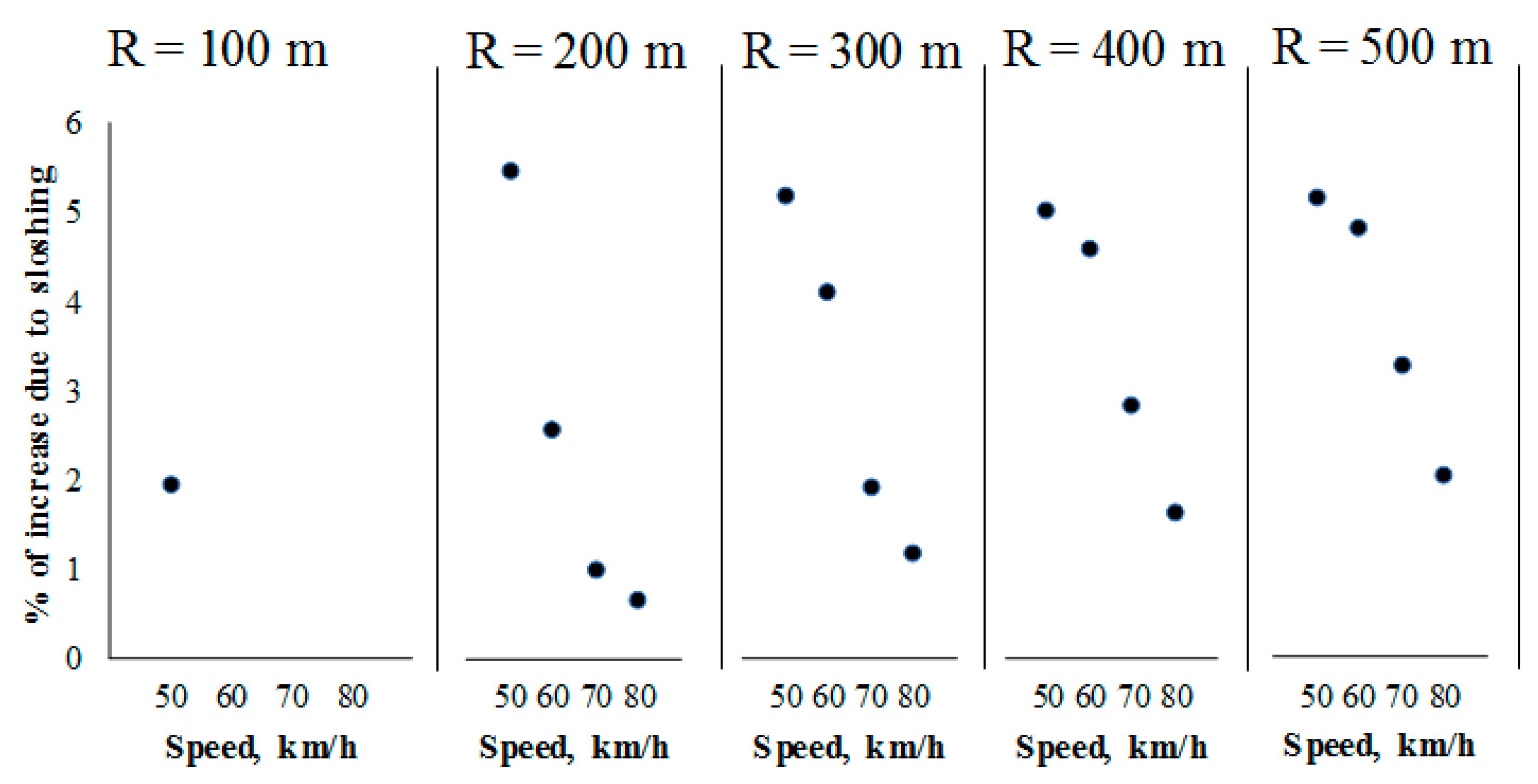
Figure 10.
Maximum values for the load transfer, as a function of speed, turning radius and cargo condition: sloshing and non-sloshing.
Figure 10.
Maximum values for the load transfer, as a function of speed, turning radius and cargo condition: sloshing and non-sloshing.


Figure 11.
Effect of cargo sloshing on the increase of the maximum load transfer coefficient, as a function of initial speed and turning radius.
Figure 11.
Effect of cargo sloshing on the increase of the maximum load transfer coefficient, as a function of initial speed and turning radius.

Table 1.
Values for the parameters and characteristics of the vehicle-cargo-ABS system.
| Property | Value | Symbol |
|---|---|---|
| Tire radius | 0.55 m | rt |
| Moment of inertia of the wheel | 90 kg m2 | Iw |
| Wheelbase | 5.95 m | 2ll |
| Suspension track width (average) | 1.7 | 2ln |
| Suspension stiffness | 500,000 N/m | K |
| Tank width | 2.4 m | L (Equation (6)) |
| Tank length | 6.6 m | L (Equation (6)) |
| Roll pendulum length | 0.906 m (0.52 Hz) | Lp,r |
| Pitch pendulum length | 4.06 m (0.24 Hz) | Lp,p |
| Chassis mass | 4000 kg | mc |
| Cargo mass (50% fill level) | 15,000 kg | mp |
| Pendulum model damping (Non sloshing) | 70,000 Ns/m | Cns |
| Pendulum model damping (Sloshing) | 8000 Ns/m | Cs |
| Angular damping for chassis | 627 Nm s/rad | C |
| Pressure buildup constant | 500,000 Pa/s | pb |
| Time constant | 0.08 s | tc |
| Set point for slip | 0.2 | SP |
| Peak braking coefficient | 0.55 | μm |
| Pressure braking torque ratio | 0.0025 Nm/Pa | Rt |
© 2018 by the authors. Licensee MDPI, Basel, Switzerland. This article is an open access article distributed under the terms and conditions of the Creative Commons Attribution (CC BY) license (http://creativecommons.org/licenses/by/4.0/).
Share and Cite
MDPI and ACS Style
Otremba, F.; Romero Navarrete, J.A.; Lozano Guzmán, A.A. Modelling of a Partially Loaded Road Tanker during a Braking-in-a-Turn Maneuver. Actuators 2018, 7, 45. https://doi.org/10.3390/act7030045
AMA Style
Otremba F, Romero Navarrete JA, Lozano Guzmán AA. Modelling of a Partially Loaded Road Tanker during a Braking-in-a-Turn Maneuver. Actuators. 2018; 7(3):45. https://doi.org/10.3390/act7030045
Chicago/Turabian StyleOtremba, Frank, José A. Romero Navarrete, and Alejandro A. Lozano Guzmán. 2018. "Modelling of a Partially Loaded Road Tanker during a Braking-in-a-Turn Maneuver" Actuators 7, no. 3: 45. https://doi.org/10.3390/act7030045
Note that from the first issue of 2016, this journal uses article numbers instead of page numbers. See further details here.