Passive Damping of Rotationally Periodic Structures with Tuned Piezoelectric Inductive Shunt
by
 , , and
Bilal Mokrani
1,* ,
,
Renaud Bastaits
2 ,
,
Iulian Romanescu
3,
Mihaita Horodinca
3,
Ioan Burda
4 and
and
André Preumont
2 
1
Department of Mechanical, Materials and Aerospace Engineering, University of Liverpool, Liverpool L69 3BX, UK
2
Department of Control Engineering and System Analysis, Active Structures Laboratory, Université Libre de Bruxelles, 1050 Brussels, Belgium
3
Department of Machine-Tools and Tools, Technical University Gheorghe Asachi, Iasi 700050, Romania
4
Physics Department, Babes Bolyai University, 400084 Cluj-Napoca, Romania
*
Author to whom correspondence should be addressed.
Actuators 2018, 7(3), 41; https://doi.org/10.3390/act7030041
Submission received: 28 May 2018
/
Revised: 20 June 2018
/
Accepted: 18 July 2018
/
Published: 19 July 2018
(This article belongs to the Special Issue Piezoelectric Actuators 2018)
Abstract
:This paper considers the piezoelectric resistive and inductive RL shunt damping applied to rotationally periodic structures equipped with an array of regularly spaced piezoelectric patches. A method for simplifying the hardware, by reducing the size of the inductors and eliminating the use of synthetic inductors, is described. The paper compares two different ways of using the piezoelectric array: independent loops and parallel loops. It shows that, if a specific mode with n nodal diameters is targeted, mounting piezoelectric patches in two parallel loops is as efficient as mounting them in independent loops, while considerably reducing the demand on the inductors, L, (by ). The method takes advantage of the mode shapes of rotationally periodic structures. The proposed method is validated numerically and experimentally on a rotationally periodic circular plate (nearly axisymmetric). The proposed technique is aimed at turbomachinery applications.
1. Introduction
New materials and new fabrication techniques in turbomachinery (e.g., blisks) lead to structures with extremely low damping which may be responsible for severe vibrations and possible high-cycle fatigue problems. There is a need for systems to increase the damping which may be achieved in various ways, blade friction damping [1], friction ring damper [2], viscoelastic damping treatment or piezoelectric shunt [3,4], to name only a few.
The use of piezoelectric transducers for damping structures has been known for a long time [5,6,7,8]; the piezoelectric transducer is used to convert mechanical energy into electrical energy, which is dissipated in an electrical network. The R-shunt involves only a network of resistors; it has limited performance, but it is simple and robust. The RL-shunt involves a set of resistors and inductors, and the electrical network is tuned to the targeted mode. Damping several modes simultaneously is possible [9,10]. The performances are superior to the R-shunt, but the electrical network needs accurate tuning of the electrical frequency on the targeted mode(s); it does not damp the other modes and, for the targeted ones, it is very sensitive to the variation in natural frequencies. For most practical applications, the value of the inductance, L, required to achieve electrical tuning, , is very large, which necessitates the use of synthetic inductors (electronic circuit called gyrator) [11]. Active components such as synthetic inductors are difficult to implement in rotating machines. It is possible to build small size passive inductors with high inductance values; nevertheless, the physical size of the inductor is proportional to the saturation current [12], which makes it impractical for high vibration levels. The problems of the passive RL-shunt may be overcome by using a switched shunt [13]; it does not require precise tuning, nor a large inductor, but switching synchronization is an issue, particularly when several vibration modes are involved, and, once again, active circuits make this solution impractical for rotating machines. In this paper, a practical solution is developed which has the potential for industrial application.
In turbo machines, the blades are subjected to excitation frequencies which are multiples of the rotation speed, (depending on the number of stator vanes). The normal modes of rotationally periodic structures consist of harmonically varying displacements in the circumferential direction which makes them very similar to axisymmetric structures [14]. Not all of them need to be damped; depending on the geometry of the stator part and the operating speed of the rotor, it is possible to identify the critical mode with a number, n, of nodal diameters which is likely to be excited and must be targeted for damping. For a particular mode with n nodal diameters, this paper explains and demonstrates how an array of piezoelectric transducers can be arranged in order to reduce the demand on the passive inductor, L, of an RL-shunt. The demonstration is limited to a circular plate equipped with 12 piezoelectric transducers. Implementation on a bladed drum, typical of turbomachinery, has been presented in [15,16].
The paper is organized into five main sections. Section 2 recalls the resonance conditions of rotationally periodic structures, excited with rotating forces. Section 3 describes the proposed resonant shunt method. Section 4 describes the experimental setup used for demonstration, while Section 5 and Section 6 are, respectively, devoted to the numerical and experimental results. Finally, the outcomes are summarized in the Conclusions section.
2. Resonance Condition
The forced response of periodic structures to a rotating axial point force has been analyzed by Wildheim [14]. For a rotationally symmetric structure excited by a constant rotating force (at ), the resonance of the mode with n nodal diameters is obtained when the natural frequency satisfies
where s is the number of nodal circles. For a rotationally periodic structure with N identical substructures, such as bladed disks or circular saws, the excitation force is also periodic with the same period as the structure; additional resonance possibilities exist, given by
where .
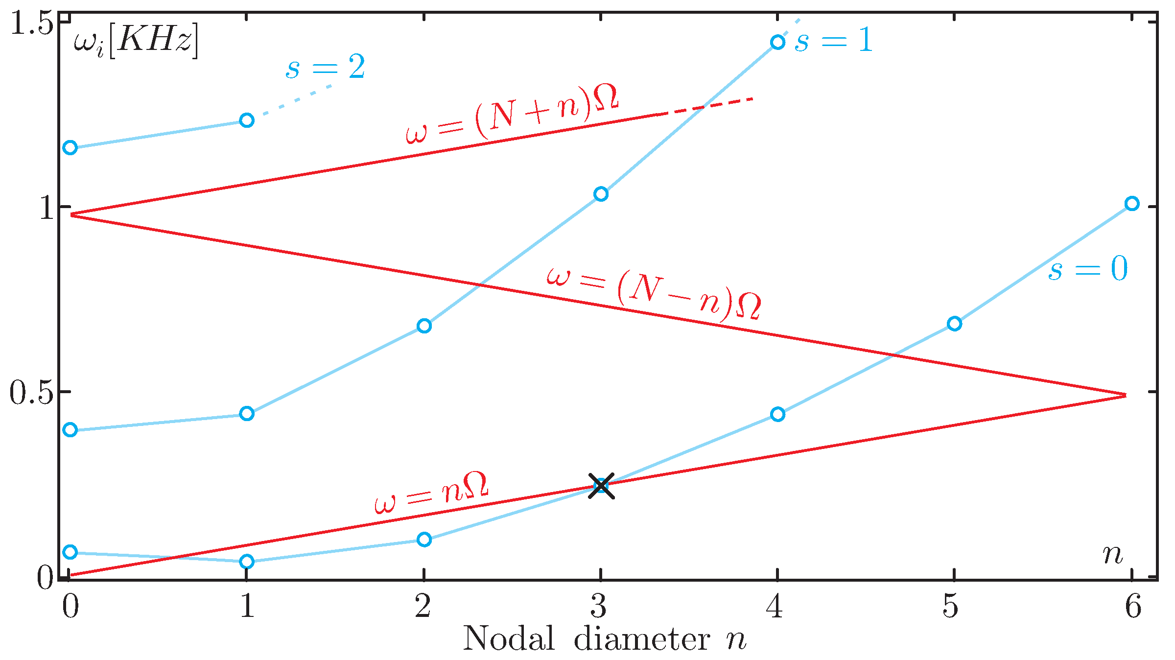
For an excitation consisting of several rotating point forces, the resonance condition is more elaborated and involves a double equality [14] which is not necessary for the present discussion. Resonance condition (2) is illustrated in Figure 1; the structure considered exhibits a periodicity of , with the same periodicity assumed for the rotating force. The zig-zag excitation lines, , correspond to a given rotation speed; if increases, the excitation line expands like an accordion along the frequency axis. All the intersections between the two sets of lines, provided they occur at an integer value of n, correspond to a resonance condition. If the crossing occurs in the ascending part of the zig-zag line [], the resonant response consists of a forward rotating wave in the direction of the excitation; if the crossing occurs in the descending part of the zig-zag line [], the resonant response consists of a backward traveling wave. In the example, the resonance (indicated by ×) corresponds to (and ). All of this is discussed in detail by Wildheim; the only point we want to make here is that, for a given application, it is possible to identify the critical mode whose damping must be enhanced. Its natural frequency, , will fix the tuning frequency of the RL shunt; the use of information about the number of nodal diameters, n, is the main concern of our discussion.
3. Damping a Mode with n Nodal Diameters
3.1. Independent Loops
Consider the disk of Figure 2, vibrating according to its mode, , , in order to simplify the notations, the resonance frequency is denoted by . The disk is equipped with a set of piezoceramic (PZT) patches; the circular plate itself is rotationally symmetric, but the presence of the piezoelectric patches makes it rotationally periodic. The PZT patches work in mode; they are located close to the periphery, so as to maximize the strain energy in the patches (and consequently, the modal effective electromechanical coupling factor). The disk, made of conducting material, constitutes the reference ground potential (). The cosine mode and the sine mode have identical frequencies.
The most obvious way to use a set of PZT patches for damping is to connect them in many independent inductive loops; if C is the capacitance of one patch, the inductor of the RL circuit will be taken as equal to
According to the classical theory of inductive shunt damping, for a single patch of capacitance, C, the optimum value of the resistor is , where is the effective electromechanical coupling factor of one PZT patch. If a number, , of patches are symmetrically located in such a way that they have the same fraction of modal strain energy for the targeted mode, , is multiplied by , and it can be shown that the optimum resistance is multiplied by compared to the case with a single transducer [17]. The optimal resistance, R, which maximizes the damping of the targeted mode, is thus given by
In order to maximize the energy conversion, the patches should be sized in such a way that the curvature has the same sign along the patch—if different parts of the same patch have opposite curvatures, the electric charges that they produce will cancel each other out. This advocates for patches of relatively small surface area, resulting in a small capacitance, C, so that Equation (3) leads to a large value of L which is impractical to realize with passive components. As an example, a PZT of 40 mm × 10 mm × 200 m has a capacitance of nF; for a natural frequency of 250 Hz, H.
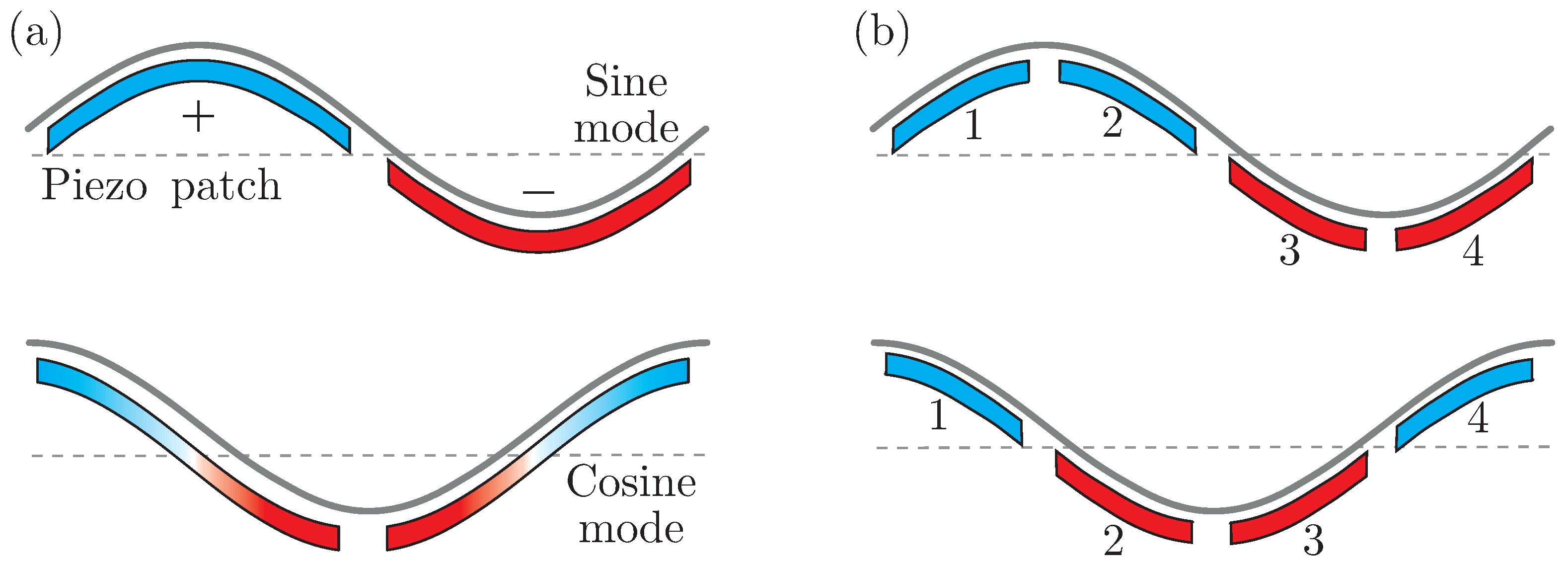
More specifically, since the cosine and the sine modes are 90° out of phase, the antinodes of the cosine modes correspond to the nodes of the sine modes and, if the patches are laid in such a way that there are only two patches per nodal diameter; that is, if one patch covers one lobe of the mode shape (Figure 3a), the curvature cannot be kept at the same sign over the entire patch, simultaneously for the sine and the cosine mode. On the contrary, if the patches are laid in such a way that there are four patches per diameter (or a multiple of), as in Figure 3b, it is possible to achieve a curvature with a uniform sign over the entire patch, simultaneously for the sine and the cosine modes.
The independent loop architecture does not take advantage of the shape of the mode with n nodal diameters. The parallel architecture discussed below does, and actually works as a modal filter.
3.2. Parallel Loops
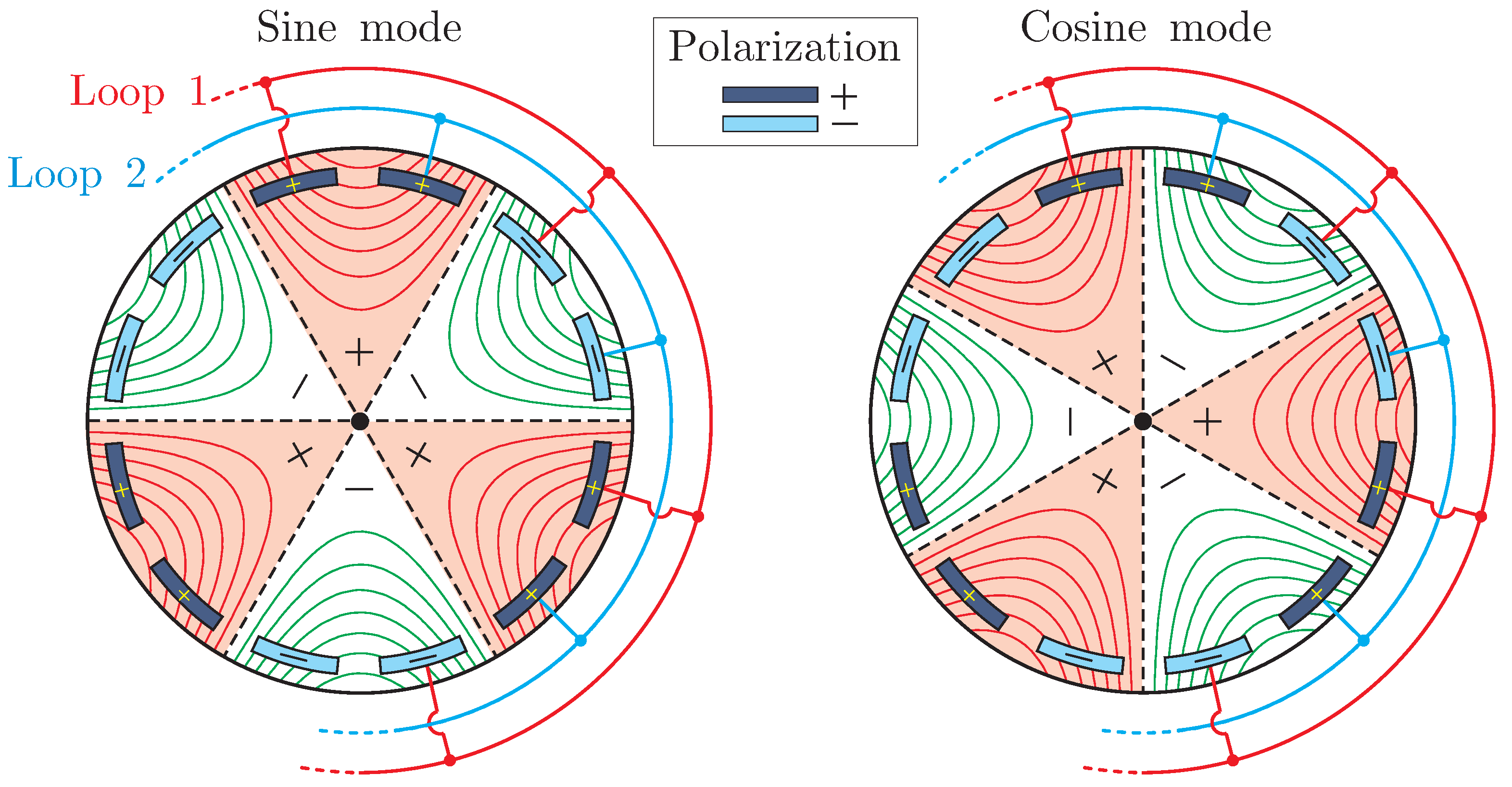
Referring to Figure 3b, it can be observed that the patches numbered 1 and 3 have curvatures of opposite signs for both the sine and cosine modes, and a similar pattern is shown for patches 2 and 4. It is therefore suggested that these pairs of patches could act together. If mounted with opposite polarization, patches 1 and 3 can be connected in parallel (and similarly for patches 2 and 4). For a + polarization, the polarization vector points upwards, and a positive curvature will produce a positive charge, while for a − polarization, the polarization vector points downwards, and a positive curvature will produce a negative charge. Thus, two PZT patches mounted in parallel will act as a single patch with double capacitance. The connection in parallel is extended to the patches acting in the other lobes of the mode shape, leading to the layout of Figure 4—the patches are mounted by pairs with identical polarization, with the next pair having inverted polarization.
Therefore, in order to increase the apparent capacitance of the PZT patches, we propose to connect the patches in parallel, as indicated in Figure 4: Two independent circuits are constituted, connecting patches in parallel, with alternating polarization separated by an angle of . Thus, since the capacitance of a single circuit is now instead of C, the number of inductors is reduced from to only 2, and the inductance of each loop is reduced to
The overall inductance requirement is reduced by , since only two inductors are needed instead of , and the size of each of them is smaller compared to the independent configuration. The optimal resistance is given by
4. Experimental Setup
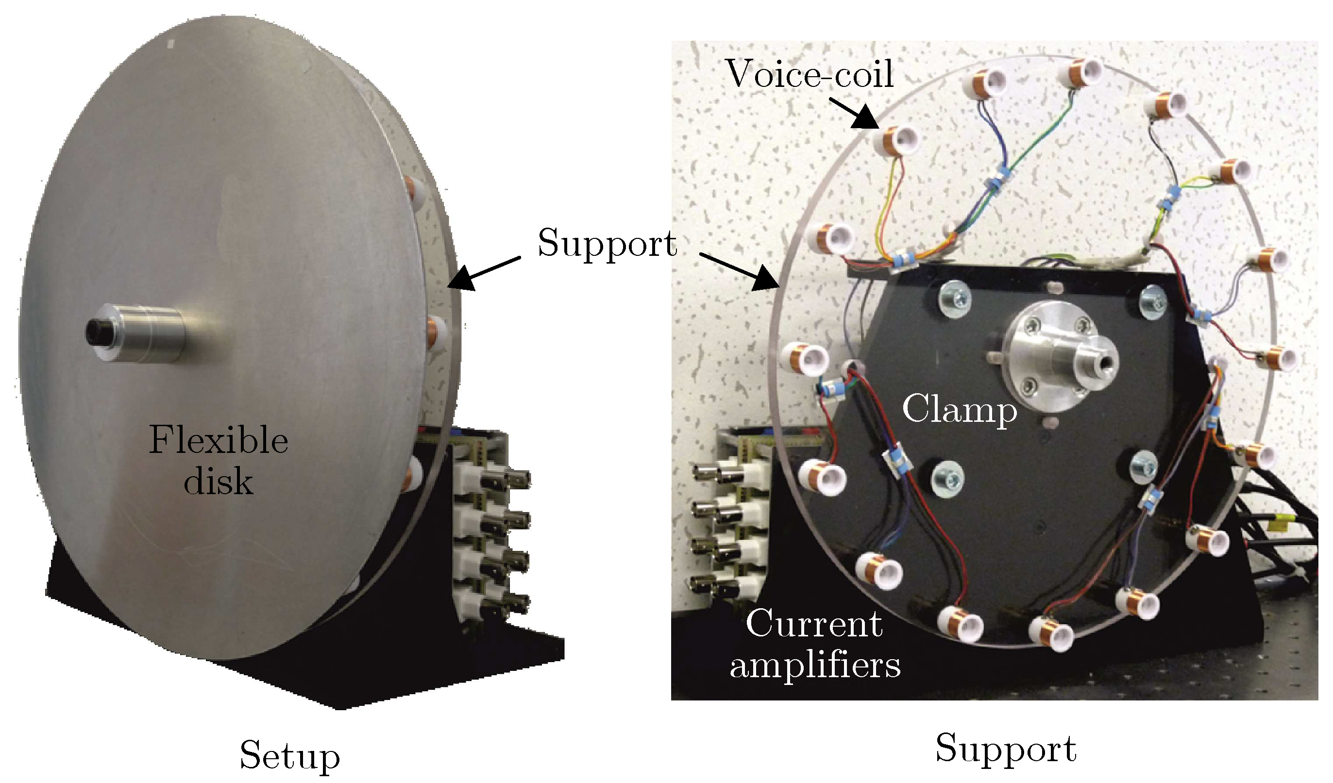
The experimental setup is represented in Figure 5; it consists of an aluminum disk of 300 mm diameter and 2 mm thickness, clamped in the center. It is equipped with 12 PZT rectangular patches with dimensions of 40 mm × 10 mm × 200 m (PIC255 from P-I). The patches are glued in such a way that the polarization matches that of Figure 4. A set of 12 synthetic inductors provides 12 independent RL channels. A set of 16 non-contact voice coil actuators interacting with small permanent magnets attached to the disk (each magnet weights 1.9 g) provide 16 independent point force excitations which may be used to excite specific modes (appropriate excitation), including rotating ones. The voice coils are connected to an array of 16 current amplifiers which are controlled by a dSpace DSP board. Figure 6 shows photos of the various parts of the setup.
Note that, because of the added mass of the 16 magnets and the contribution of the 12 PZT patches to the mass and stiffness of the plate, the setup slightly departs from being strictly rotationally periodic; however, this situation is not unusual in rotating machines, and it has been verified that the cosine and sine modes with nodal diameters do have the same natural frequency, as can be seen below (Table 1).
Excitation
If m actuators ( in this case) are separated by , the appropriate excitation with n diameters for the cosine mode (and amplitude, F) reads
All excitation forces act in phase with a spatial shape which matches that of the cosine mode. By rotating this excitation by 90°, one gets the appropriate excitation for the corresponding sine mode.
A progressive rotating excitation with n diameters is achieved with
All forcing functions have the same frequency, , but a phase shift is introduced between them in such a way that the spatial shape is that of a rotating cosine mode with n nodal diameters; the rotation speed of the progressive wave is . Note that, a rotating mode may also be generated by exciting the structure at only two points separated by 90° by using harmonic forces of equal amplitude and phase shifted by .
5. Numerical Simulation
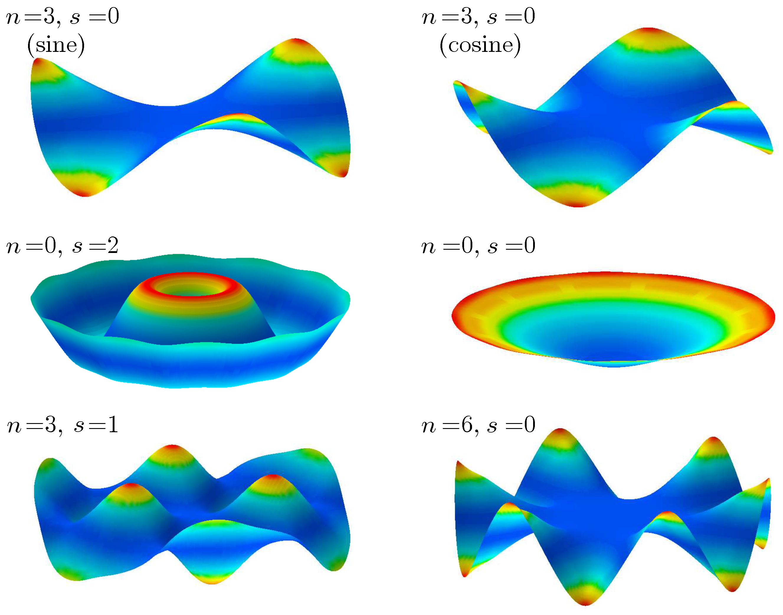
The system was modeled with finite element software SAMCEF. The plate was discretized with piezoelectric Mindlin plate elements [18]. Table 1 shows the numerical values of the natural frequencies of a few low frequency modes; the modes occurred in pairs with nearly equal frequencies, in spite of the slight dissymmetry. Figure 7 shows the shapes of the few first modes. The model was written in modal coordinates and transferred in MATLAB in state variables form.
The RL shunt parameters are summarized in Table 2, where the resistor and the inductor are considered to be mounted in series. They were calculated with Equations (3)–(6), based on the numerical model; the experimental parameters were nearly identical. The generalized electromechanical coupling factor of each patch was identical for both the sine and the cosine modes with three nodal diameters. It is given by [17]:
where the superscript j denotes the j-th PZT patch, and and are, respectively, the resonance frequencies of the three nodal diameters’ modes, when the electrodes of the j-th PZT are short-circuited and when they are open while the electrodes of the other PZTs are maintained short-circuited. For both the experimental and the numerical models, was equal to ∼ This value was used to calculate the optimal resistance, R.
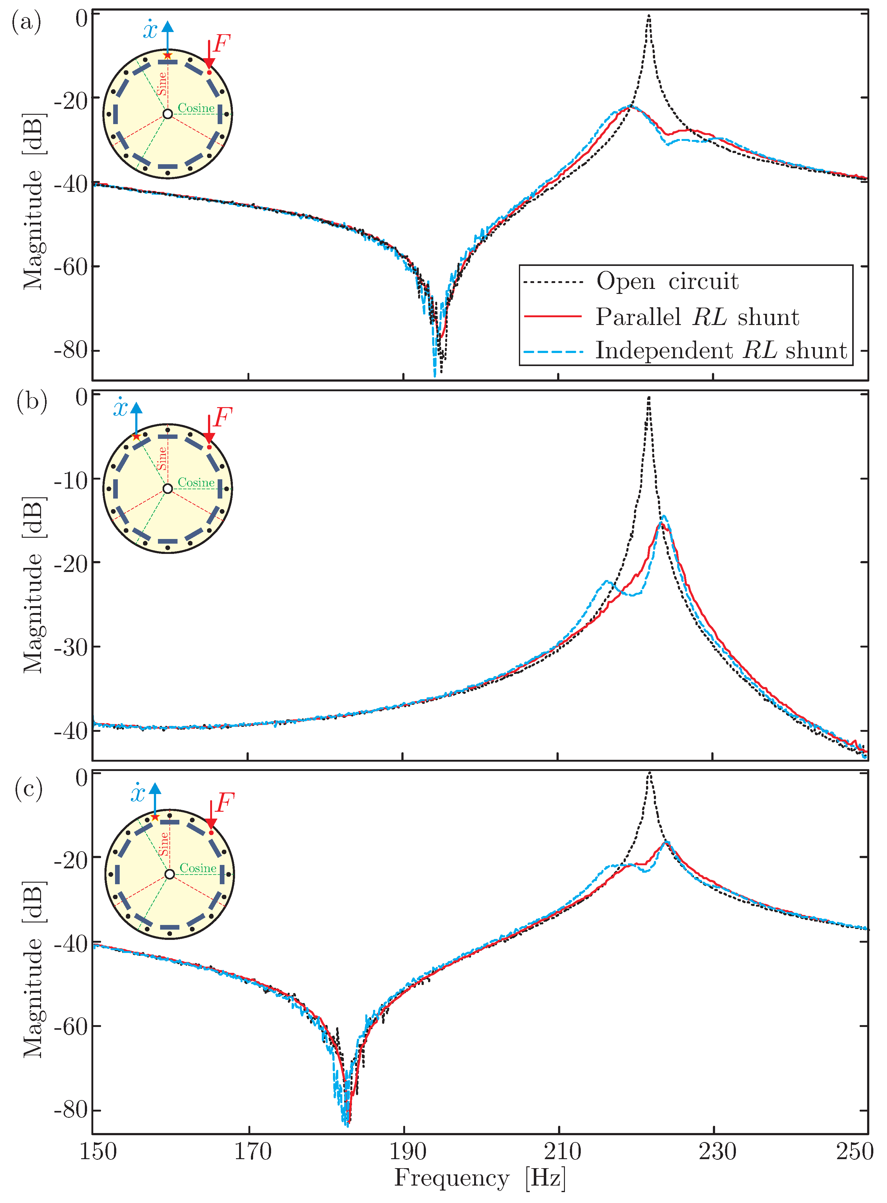
The numerical comparison between the independent RL shunt (12 independent loops) and the parallel shunt (two loops involving six PZT patches each) is shown in Figure 8. The figure compares the Frequency Response Function (FRF) between a point force, F, and the plate velocity, , at three different points. Figure 8a corresponds to the point where the response of the sine mode is maximized; Figure 8b corresponds to the point where the response of the cosine mode is maximized; and Figure 8c is in the middle where both modes contribute to the response. In each case, the two curves corresponding to the independent shunt and the parallel shunt are on top of each other; the dotted lines correspond to the system without shunt (a natural damping of 0.5% is estimated from measurements).
6. Experimental Results
The experimental comparison between the independent RL shunt (12 independent loops) and the parallel shunt (2 loops involving six PZT patches each) is shown in Figure 8. In both cases, synthetic inductors were used. The figure compares the FRF between a point force, F, and the plate velocity, , (obtained without contact with a laser vibrometer) at three different points. Figure 9a corresponds to the point where the response of the sine mode is maximized; Figure 9b corresponds to the point where the response of the cosine mode is maximized; and Figure 9c is in the middle where both modes contribute to the response. The curves are no longer on top of each other, but the two strategies exhibit similar performances. The slight difference between the two curves is reported as being due to the small difference between the PZT patches and to the fact that the 12 resistors and inductors were tuned manually using potentiometers, and thus, depart slightly from being optimal.
7. Conclusions
The motivation of this study was the simplification of the hardware of the RL shunt damping when applied to rotationally periodic structures by reducing the demand on the inductors (and possibly eliminating the use of synthetic inductors). The study assumes that a specific mode with n nodal diameters has been identified as critical and is targeted for damping. The transducer array consists of PZT patches regularly spaced; two network architectures were compared: independent loops and parallel loops. It was shown that mounting PZT patches in two parallel loops is as efficient as mounting them in independent loops, and it reduces the demand on the inductors, L, in the circuits by . The strategy was illustrated numerically on a circular plate, and the numerical results were confirmed experimentally. The proposed approach offers a practical solution (with fully passive components) to the shunt damping of targeted modes in rotating structures, thus avoiding the use of synthetic inductors. The presented approach was validated on a bladed drum typical of turbomachinery in a separate study [16].
8. Patents
The promising results arising from this paper have justified a patent application by our industrial partner in this project [19].
Author Contributions
This work has been conducted in the framework of B.M. PhD studies, under the supervision of André Preumont. M.H., I.R. and I.B. contributed to the realization of the experimental setup. R.B. participated to the whole project, and had several contribution to the paper. All the authors contributed equally to the study.
Funding
This project was funded by the “Skywin” program of Région Wallonne with Techspace Aero (Groupe SAFRAN) as industrial partner.
Acknowledgments
The authors thank R. Viguié from SAFRAN Aeroboosters for his fruitful discussions and his support during the whole project.
Conflicts of Interest
The authors declare no conflict of interest.
References
- Griffin, J.H. A review of friction damping of turbine blade vibration. Int. J. Turbo Jet Engines 1990, 7, 297–308. [Google Scholar] [CrossRef]
- Laxalde, D.; Thouverez, F.; Lombard, J.P. Force response analysis of integrally bladed disks with friction ring dampers. J. Vib. Acoust. 2010, 1, 132. [Google Scholar]
- Tang, J.; Wang, K.W. Vibration control of rotationally periodic structures using passive piezoelectric shunt networks and active compensation. J. Vib. Acoust. 1999, 121, 379–390. [Google Scholar] [CrossRef]
- Kauffman, J.; Lesieutre, G. Piezoelectric-based vibration reduction of turbomachinery bladed disks via resonance frequency detuning. AIAA J. 2012, 50, 1137–1144. [Google Scholar] [CrossRef]
- Forward, R.L. Electronic damping of vibrations in optical structures. Appl. Opt. 1979, 18, 690–697. [Google Scholar] [CrossRef] [PubMed]
- Forward, R.L. Electronic damping of orthogonal bending modes in a cylindrical mast experiment. AIAA J. Spacecr. 1981, 18, 11–17. [Google Scholar] [CrossRef]
- Hagood, N.W.; von Flotow, A. Damping of structural vibrations with piezoelectric materials and passive electrical networks. J. Sound Vib. 1991, 146, 243–268. [Google Scholar] [CrossRef]
- Kozlowski, M.V.; Cole, D.G.; Clark, R.L. A comprehensive study of the RL series resonant shunted piezoelectric: A feedback control perspective. J. Vib. Acoust. 2011, 133, 011012. [Google Scholar] [CrossRef]
- Lossouarn, B.; Deü, J.F.; Aucejo, M.; Cunefare, K.A. Multimodal vibration damping of a plate by piezoelectric coupling to its analogous electrical network. Smart Mater. Struct. 2016, 25, 115042. [Google Scholar] [CrossRef] [Green Version]
- Hollkamp, J.J. Multimodal passive vibration suppression with piezoelectric materials and resonant shunts. J. Intell. Mater. Syst. Struct. 1994, 5, 49–57. [Google Scholar] [CrossRef]
- Antoniou, A. Realisation of gyrators using operational amplifiers, and their use in RC-active-network synthesis. Proc. Inst. Electr. Eng. 1969, 116, 1838–1850. [Google Scholar] [CrossRef]
- Lossouarn, B.; Aucejo, M.; Deü, J.F.; Multon, B. Design of inductors with high inductance values for resonant piezoelectric damping. Sens. Actuators A Phys. 2017, 259, 68–76. [Google Scholar] [CrossRef] [Green Version]
- Guyomar, D.; Richard, C. Non-linear and hysteretic processing of piezoelement: Application to vibration control, wave control and energy harvesting. Int. J. Appl. Electromagn. Mech. 2005, 21, 193–207. [Google Scholar]
- Wildheim, S.J. Excitation of rotationally periodic structures. J. Appl. Mech. 1979, 46, 878–882. [Google Scholar] [CrossRef]
- Mokrani, B.; Bastaits, R.; Horodinca, M.; Romanescu, I.; Burda, I.; Viguié, R.; Preumont, A. Passive piezo damping of rotationally periodic structures with application to a bladed drum. In Proceedings of the International Conference of Noise and Vibration Engineering (ISMA2014), Leuven, Belgium, 15–17 September 2014; pp. 667–682. [Google Scholar]
- Mokrani, B.; Bastaits, R.; Horodinca, M.; Romanescu, I.; Burda, I.; Viguié, R.; Preumont, A. Parallel piezoelectric shunt damping of rotationally periodic structures. Adv. Mater. Sci. Eng. 2015. [Google Scholar] [CrossRef]
- Mokrani, B. Piezoelectric Shunt Damping of Rotationally Periodic Structures. Ph.D. Thesis, Université Libre de Bruxelles, Active Structures Laboratory, Brussels, Belgium, 2015. [Google Scholar]
- Piefort, V. Finite Element Modeling of Piezoelectric Active Structures. Ph.D. Thesis, Université Libre de Bruxelles, Active Structures Laboratory, Brussels, Belgium, 2001. [Google Scholar]
- Viguié, R.; Verhelst, D.; Preumont, A.; Mokrani, B.; Bastaits, R. Piezoelectric Damper System for an Axial Turbomachine Rotor. Patent US20150104295A1, CA2866756A1, CN104564798A, EP2860405B1, 16 April 2015. [Google Scholar]
Figure 1.
Natural frequencies versus number of nodal diameters and zig-zag-shaped excitation lines for a given rotation speed . In the example, , and the resonance condition is achieved for and ; it is indicated by ×.
Figure 1.
Natural frequencies versus number of nodal diameters and zig-zag-shaped excitation lines for a given rotation speed . In the example, , and the resonance condition is achieved for and ; it is indicated by ×.

Figure 2.
Disk vibrating in the mode , , equipped with 12 piezoceramic (PZT) patches regularly spaced on the disk.
Figure 2.
Disk vibrating in the mode , , equipped with 12 piezoceramic (PZT) patches regularly spaced on the disk.

Figure 3.
PZT patches laid with (a) two patches per nodal diameter; (b) four patches per nodal diameter. The colors indicate the sign of the curvature. In the configuration with four patches per nodal diameter, the patches numbered 1 and 3 have curvatures of opposite signs for both the sine and cosine modes, and similarly for the patches numbered 2 and 4.

Figure 4.
Disk vibrating in the mode , , equipped with patches of PZT regularly spaced on the disk: (Left) sine mode (Right) cosine mode. The colours of the PZT patches indicate the polarization. The electrical connections between the patches are also indicated.
Figure 4.
Disk vibrating in the mode , , equipped with patches of PZT regularly spaced on the disk: (Left) sine mode (Right) cosine mode. The colours of the PZT patches indicate the polarization. The electrical connections between the patches are also indicated.

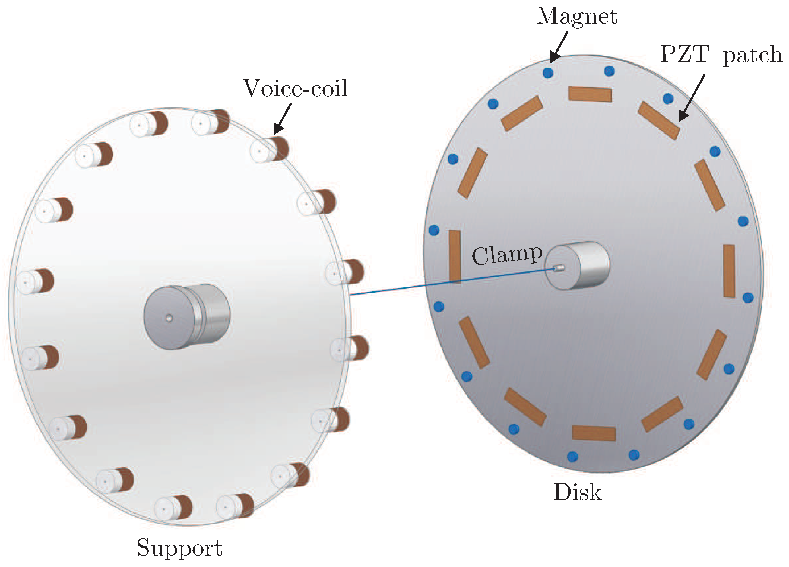
Figure 5.
CAD view of the experimental setup with 12 PZT patches. Two different electrical connections are investigated according to Figure 4: (i) 12 independent loops and (ii) two parallel loops. The voice coil and magnets are intended for non-contact excitation; they are connected to 16 independent current amplifiers.

Figure 6.
View of the experimental setup. (Left) Plate mounted on its central support; the PZT patches are located on the opposite side of the plate. (Right) Set of voice coils used to excite the plate.
Figure 6.
View of the experimental setup. (Left) Plate mounted on its central support; the PZT patches are located on the opposite side of the plate. (Right) Set of voice coils used to excite the plate.

Figure 7.
Mode shapes of the disk equipped with 12 PZT patches and 16 small magnets. The modes are almost harmonic and very close to those of a perfectly axisymmetric disk.
Figure 7.
Mode shapes of the disk equipped with 12 PZT patches and 16 small magnets. The modes are almost harmonic and very close to those of a perfectly axisymmetric disk.

Figure 8.
Simulation results: Frequency Response Function (FRF) between F and . Comparison between the independent shunt and parallel shunt for the first mode with nodal diameters. In all cases, the curves are on top of each other. The dotted lines correspond to the original system with a natural damping of 0.05%. (a) is measured at the point where the sine mode is maximized. (b) is measured at the point where the cosine mode is maximized. (c) is measured in the middle where both modes contribute to the response.

Figure 9.
Experimental results: comparison between the independent shunt and parallel shunt for the first mode with nodal diameters. The dotted lines correspond to the original system with a natural damping of 0.05%. (a) is measured at the point where the sine mode is maximized. (b) is measured at the point where the cosine mode is maximized. (c) is measured in the middle where both modes contribute to the response.


Table 1.
Computed natural frequencies, , of the circular plate (with n nodal diameters and s nodal circles).
Table 1.
Computed natural frequencies, , of the circular plate (with n nodal diameters and s nodal circles).
| ns | 0 | 1 | 2 | 3 |
|---|---|---|---|---|
| 0 | 63.08 | 374.32 | 1096.59 | 2180.32 |
| 1 | 38.69 | 415.91 | 1163.64 | 2271.23 |
| 38.69 | 415.91 | 1163.64 | 2271.23 | |
| 2 | 93.64 | 639.31 | 1490.36 | |
| 93.69 | 639.41 | 1492.67 | ||
| 3 | 223.43 | 969.06 | 1963.05 | |
| 223.43 | 969.06 | 1963.05 |
Table 2.
Shunt circuit parameters for damping the mode with three nodal diameters ( Hz).
| Parameter | Independent Loops | Parallel Loops |
|---|---|---|
| Apparent capacitance | 12 × 52 nF | 2 × 313 nF |
| Inductance L | 12 × 9 H | 2 ×1.5 H |
| Resistance R | 12 × 945 Ohm | 2× 157 Ohm |
© 2018 by the authors. Licensee MDPI, Basel, Switzerland. This article is an open access article distributed under the terms and conditions of the Creative Commons Attribution (CC BY) license (http://creativecommons.org/licenses/by/4.0/).
Share and Cite
MDPI and ACS Style
Mokrani, B.; Bastaits, R.; Romanescu, I.; Horodinca, M.; Burda, I.; Preumont, A. Passive Damping of Rotationally Periodic Structures with Tuned Piezoelectric Inductive Shunt. Actuators 2018, 7, 41. https://doi.org/10.3390/act7030041
AMA Style
Mokrani B, Bastaits R, Romanescu I, Horodinca M, Burda I, Preumont A. Passive Damping of Rotationally Periodic Structures with Tuned Piezoelectric Inductive Shunt. Actuators. 2018; 7(3):41. https://doi.org/10.3390/act7030041
Chicago/Turabian StyleMokrani, Bilal, Renaud Bastaits, Iulian Romanescu, Mihaita Horodinca, Ioan Burda, and André Preumont. 2018. "Passive Damping of Rotationally Periodic Structures with Tuned Piezoelectric Inductive Shunt" Actuators 7, no. 3: 41. https://doi.org/10.3390/act7030041
Note that from the first issue of 2016, this journal uses article numbers instead of page numbers. See further details here.