A V-Shaped Actuator Utilizing Electrostatic Force


1
Center for Intelligent & Interactive Robotics, Korea Institute of Science and Technology, Hwarangro 14gil 5, Seongbuk-gu, Seoul 02792, Korea
2
Department of Electrical Engineering, Korea University, 145 Anam-ro, Seongbuk-gu, Seoul 02841, Korea
*
Author to whom correspondence should be addressed.
Actuators 2018, 7(2), 30; https://doi.org/10.3390/act7020030
Submission received: 29 May 2018
/
Revised: 8 June 2018
/
Accepted: 12 June 2018
/
Published: 18 June 2018
(This article belongs to the Special Issue Modeling Smart Actuators and Their Applications)
Abstract
:In this study, we propose a new ‘V’-shaped actuator with two panels and experimentally and theoretically investigate its actuation to find the most efficient structure. The V-shaped actuator operates like a seesaw. Specifically, when a high voltage input is applied between the V-shaped actuator and metal plate at the bottom substrate, another panel rises due to electrostatic attraction. Both gravity and electrostatic attraction forces are utilized for the operation of the actuator. We made a model of the actuation mechanism considering torque, gravity, and electrostatic forces. Theoretical values were compared with experimental results considering all factors of force applied to actuators. Additionally, we added torque by restoring force to compensate for the experimental conditions. The theoretical value almost coincided with the experimental value with R2 = 0.9.
1. Introduction
Actuators are controllable work-producing devices with various sizes and shapes [1]. Actuators can be classified into several classes: electromagnetic, electromechanical, fluidic, piezoelectric, hybrid, and natural actuators [2,3,4,5,6,7,8]. Typical examples of electromagnetic actuator are solenoids and magnetostrictions. Electromechanical actuators include linear drives, and Microelectromechanical systems (MEMS) Comb Drives. Fluid actuators include hydraulics and pneumatics. Piezoelectric actuators are made from electromechanically coupled materials. There are also hybrid actuators, which include both piezoelectric and electromechanical characteristics. Another type is the natural actuators, such as human muscles. These actuators have different bandwidths, response rates, waveform profiles, and power requirements. Thus, they can vary greatly in stroke, force, frequency, and price.
Actuators are used in a wide variety of applications. We can find their applications from machines to automotive and augmented reality implementations, including rehabilitation robots, service robots, food-processing automation, and surgery [9,10,11,12,13]. Since all technologies have advantages and disadvantages, they are utilized depending on the purpose. For example, eccentric rotating mass motors (ERM) have advantages in price, linear resonant actuators (LRA) in price and strength, piezoelectrics of fast feedback, and electroactive polymer (EAP) in variance, but they also have disadvantages of slow reaction rates, equipment complexity, and efficiency [4,10,14,15]. Therefore, it is very important to choose the proper actuator for the specific application.
One study suggested steps to choose a suitable actuator [1]. The first step in the selection process is to choose an actuator that produces a sufficient level of force and displacement. Even if sufficient force can be generated, it is excluded unless there is sufficient capacity to produce the required displacement. The second stage of selection is frequency and weight selection. The final constraint on the actuator is that it should have an appropriate design life.
In this study, we propose a new ‘V’-shaped actuator using electrostatic force that can be controlled by voltage inputs (Figure 1). We choose electrostatic force as a power source that can show fast reaction speed, and can be compatible with various manufacturing technologies. Electrostatic actuators have been mostly used in micro and nanoscale applications, such as optical MEMS, valves, nanoswitches, RF chemical sensors, RF communication modules, and nanocantilever beams [16,17,18,19,20,21,22]. However, since the moving distance and the generated force are very small, it was difficult to functionalize a system with a single electrostatic actuator [23]. Therefore, an actuator using electrostatic force was fabricated through various hybrid techniques to compensate for the disadvantages [24,25,26,27]. In this study, gravity was used as an additional power source. In addition, the V-shaped actuator can benefit the structure by separating the displaced part from the electrostatic force region. Furthermore, the frequency of exercise is electrically adjustable and can be used repeatedly.
Herein, we theoretically and experimentally investigated the operation of the V-shaped actuator, performing a series of tests using various structures to find the most effective shape for the actuator. This actuator is V-shaped with two panels connected at a certain angle (Figure 1). One panel responds to electrostatic attraction and the other panel serves to transmit the stimulus. In particular, we changed the length of the actuator, the angle between the two panels, and the position of the axis of rotation. We modeled the motion of the actuator considering electrostatic force. The theoretical expectation was compared with the experimental results. We expect this V-shaped actuator to be used for various applications.
2. Materials and Methods
2.1. Model Fabrication by 3D Printing
Models were designed using Solidworks software (Dassault Systems Solidworks Corp., Waltham, MA, USA). The models were made of part (VisiJet M3 Crystal, 3D Systems Inc., Rock Hill, SC, USA) and supporter (VisiJet S300, 3D Systems Inc., Rock Hill, SC, USA) materials using a 3D printer (ProJet HD3500, 3D Systems Inc., Rock Hill, SC, USA). After printing, the models were put into a convection oven (DCF-31-N, Dae Heung Sceince, Incheon, Korea) for melting wax. Lastly, the wax was completely removed from the models in an oil bath of ultrasonic cleaner (Sae Han Ultrasonic Co., Seoul, Korea).
2.2. Circuit Configuration and Set Up
5V, 3A electricity from a power supply (PS280, Tektronix, Beaverton, OR, USA) and 0.5 Hz function from waveform generator (33500Bseries, Keysight Technologies, Santa Rosa, CA, USA) were supplied to a DC converter (AG 50P-5, XP Power, Singapore) for voltage amplification (5 kV). A 50 MΩ thick film resistor (Ohmite, Warrenville, IL, USA) was also connected to the DC converter for electric charge release.
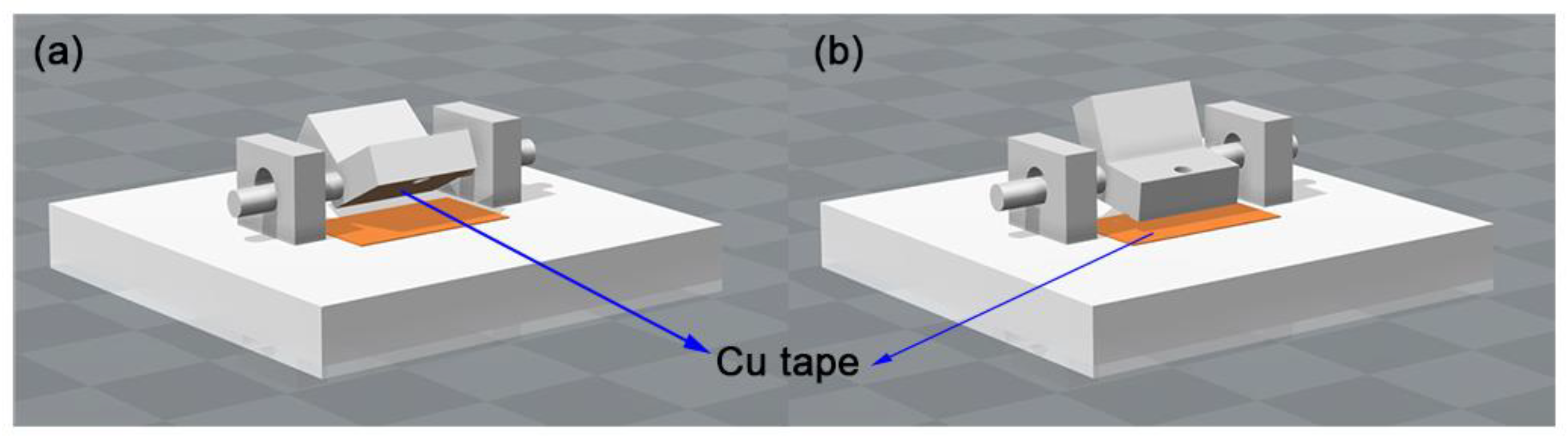
Thin wire passed through the pore of the V-shaped actuator and was covered with copper tape (1181, 3M, Maplewood, NJ, USA) under the actuator. The bottom of V-shaped actuator was connected to (+) potential (Figure 2). On the other hand, the copper tape was also attached on the bottom substrate and covered with PET film (100 μm thickness, Saehan, Paju, Korea). The copper tape on the substrate was connected to the (−) terminal of the DC converter.
2.3. Motion Tracing and Angle Measurement
Position changes of the V-shaped actuator were detected using a laser sensor (IL-100 Intelligent Laser sensor, Keyence Corp., Osaka, Japan). The distance change was measured with 2000 Hz, and data was transferred and logged on a computer through a Data Acquisition (DAQ) Board (USB-6343, National Instruments, Austin, TX, USA). Through the distance changes, the angle changes were estimated easily with law of sines. The data was depicted as a dot graph with fitting line. For detecting motion detail, the motion was captured using a 4K camera (DSC RX10M3, Sony, Minato, Japan with lens (Vario-Sonnnar T*, Zeiss, Oberkochen, German)) at 240 frame rate in HFR mode.
3. Results
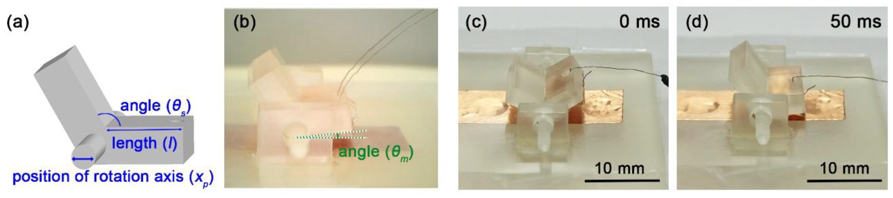
Various prototypes of simple V-shaped actuators were fabricated using a 3D printer. For investigating the motion-effective form, the length of panel (l), angle between two panels (θs), and position of rotation axis (xp) were changed (Figure 3a). The specific size information of all the samples used in the experiment is shown in Supplementary Table S1.
When different types of electrical charges (+, −) are supplied to the two copper tapes on the actuator and bottom substrate, respectively, attractive force is generated. The V-shaped actuator loses its balance and approaches the copper tape that is attached to bottom substrate (Figure 3c,d). When the lower panel attaches to the base, the other panel stands up in the air. The actuators produced in this study are of seesaw type and have a symmetrical ‘V’ shape in which two panels of the same length are connected with a certain angle between them. Because each panel defines the electrostatic area and the displacement, the length, angle, and position of the rotation axis of the panel have a decisive influence on the actuator’s motion.
Length effect experiments were performed with 5.5 mm (sl1), 7 mm (sl2), 8.5 mm (sl3), and 10 mm (sl4) panels; the angle between the two panels and the position of rotation axis were fixed (θs = 2.09 rad, xp = middle (③)) (Supplementary Table S1). Long panels offered wide surface area for copper, leading to strong attractive force: the length of the charged parallel electrode proportionally increases the attractive force. As the length of the panel becomes longer, the cross-sectional area of the panel becomes wider, and the copper tape covering the panel also becomes larger. The increase in the cross-sectional area of the conductor leads to an increase in the magnitude of the force. The relationship can be found by the following equation [28].
When the parallel capacitor plates are modeled as charged parallel planes, with the total charge q, the magnitude of the electrostatic force (F) exerted on the plate is expressed as Equation (1). Here, E, A, ε0, ΔV, and d signify electric field, metal plate area, permittivity of free space, voltage difference, and distance between two parallel electrodes, respectively.
As the length of the panel increases, the area for charges increases, and the electrostatic attraction increases together.
Parasitic capacitance may occur when two electrical conductors are close to each other at different voltages, which lowers the overall operating load resistance [29,30,31]. In this study, a 50 MΩ resistor is loaded and this resistor helps to release the charge.
In addition, to comprehensively calculate the torque, not only the torque from the attractive force but also the torque due to the gravity must be considered. The length of the panel also affects the torque [32].
Torque, τg, can be obtained by multiplying the mass m, gravitational acceleration g, distance l between the center of mass (COM) and the rotation axis, and sine value of angle θ between the gravity and the direction from the rotation axis to COM. From Equation (2), we note that the length term can affect this gravitational torque through changing COM.
Furthermore, the length affects inertia momentum (I), which has a very large effect on rotation [33].
where a and h denote the length and thickness of the panel, respectively. Length is related to various variables, such as the attractive force, the gravitational force, and the inertia momentum, so it is essential to compare the effect of the length of the actuators experimentally to find the performance change of the actuator. In addition, the weight increases as the length increases, and the inertia momentum is affected not only by the length but also by the weight. In order to obtain the angular acceleration (α), the torque must be divided by the inertia momentum value, so the length change plays a very important role in the rotation of the actuator [34].
The initial angle was determined to be deviated in the direction of movement within about 0.09 rad from the equilibrium angle; that is, the angle to start the actuation by electrostatic force. As the length increases, the attractive force and torque increase. Although sl4 took the longest time, it exhibited the largest angle of motion (Figure 4). This seems to be due to the fact that the length change has a positive effect on the actuation because the added torque is greater than the increase of the inertia momentum.
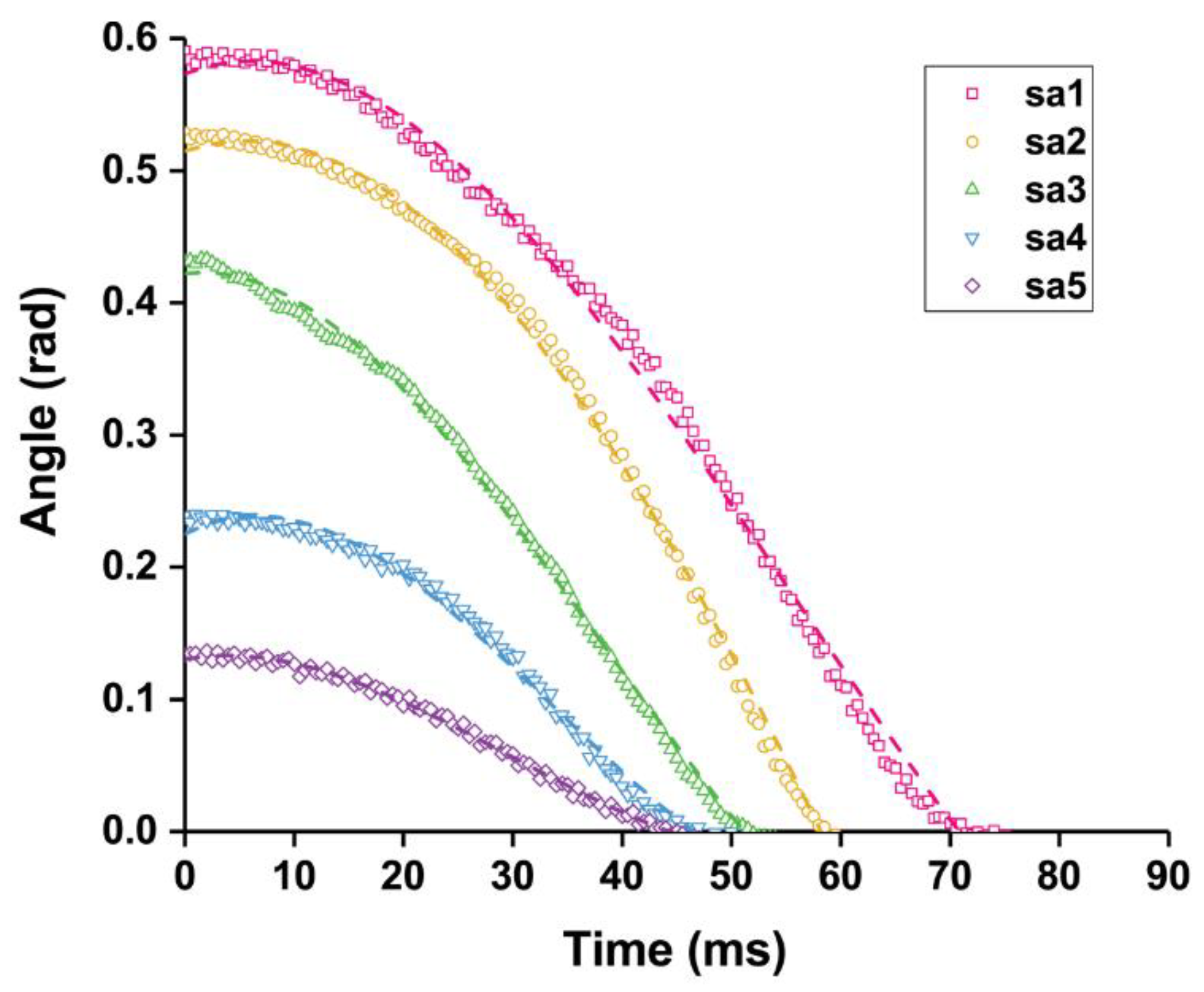
When the angle between the two panels (θs) is changed, the range of motion that can be exercised is different. As the angle between the panels decreases, the moveable angle increases and more movement is possible.
Five different angles of V-shaped actuators were used in the experiments (θs = 1.57 rad (sa1), 1.83 rad (sa2), 2.09 rad (sa3), 2.36 rad (sa4), and 2.62 rad (sa5)); the length of panel and position of rotation axis were fixed (l = 7 mm, xp = middle(③)) (Supplementary Table S1). The sa1 has the widest possible radius to move. For sa1, the angle between the panels is 1.57 rad and the moveable angle for action (θm0) is 0.79 rad when it is perfectly balanced at the center. This radius of motion is 0.52 rad wider than sa5 with an angle of 2.62 rad between the panels (Figure 5). The initial instantaneous velocities were all similar but gradually changed.
Changing the position of the rotational axis (xp) affects the COM and momentum of inertia and can imbalance the seesaw. Thus, sx1 (①), sx2 (②), sx4 (④), and sx5 (⑤) have positions of the rotational axis that are slightly off-center. The length of the panels and the angle between them were fixed (l = 7 mm, θs = 2.09 rad) (Figure 6a) (Supplementary Table S1). Because of the rotation axis changes, the center of gravity is broken and hardly moves (Figure 6b). When the position of the rotational axis is near the middle of the V-shaped actuator (sx3) or is slightly offset to the rear, the actuator (sx4) can move well.
Thus, the actuator showed different movements depending on the length, angle, and axis position. Above all, the V-shaped actuator moves within a few tens of ms scale and thus, it has rapid response and operation.
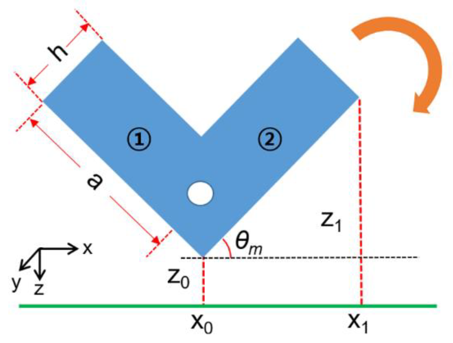
The angular acceleration can be calculated from the total torque and inertia momentum of the V-shaped actuator (Figure 7). The total torque (τtotal) is described as the sum of torques by the electric force (τe) and gravity force (τg). Since there is a slight gap (z0) between the bottom and the V-shaped actuator for operation and the V-shaped actuator is tilted, τe should be calculated as follows [35],
where y1 denotes the width of panel in y-axis, and θm(t) signifies the moving angle change of sample with time. As the V-shaped actuator approaches the bottom, the angle θm is changed, and it leads to different attractive force. Gravity’s effect on torque can be calculated as follows:
dcom is the distance between the center of mass and position of rotational axis in z-axis (Figure 7).
Moreover, we need to calculate the inertia momentum to calculate the angular acceleration. We calculated the mass inertia momentum with Equation (3). Lastly, the angular acceleration, αm, is calculated as follows [34],
Using the formula, we calculated the angular acceleration, αm, of sl2 (values for theoretical model is in Table 1).
In addition, we refer to a study with an analytical model of torque influenced by electrostatic force in a similar structural condition [36].
Both theoretical graphs are similar each other, however, it is slightly different with experimental data (Figure 8). This difference can be attributed to the effect of restoring force including resistance [36]. Considering this effect, we present the effect as the minus torque (τR) as restoring force with a coefficient, k [36].
We show theoretical predictions at 3 different coefficients for restoring force (k = 0.0038, 0.0040, and 0.0042) (Figure 8). By considering restoring torque, when k is 0.0038, the curve of the theoretical value becomes well matched to the experimental value with R2 = 0.9: the slope and operating time were similar.
4. Discussion
In this study, we proposed a new type of actuator and conducted experiments to optimize its structure. We found that long panel length with a small angle between them showed large movements. Also, it was confirmed that the rotational axis of the V-shaped actuator should be located at the center to move well.
We considered the torque of electrostatic force and gravitational force as sources for the rotation of the V-shaped actuator. Additionally, we added the torque by restoring force to compensate for the experimental conditions. In good agreement, the theoretical value almost coincided with the experimental value.
Likewise, in this study, we developed a new type of ‘V’ actuator. The ‘V’ actuator has a large displacement because the electrostatic region and the displacement part are separated. It also uses both gravitational and electrostatic forces to operate and its movement is large and fast. Therefore, it is suitable for application to actuating systems, such as industrial pumps and household appliances which require large and fast displacement and can use fixed positions in order to have greater motion efficiency. In addition, the structure is simple, light, the size can be adjusted, and most of all, since electricity does not flow to the displacement part, it can be applied to tactile systems which are directly contacted by humans. It is a compact device that is very effective at delivering stimuli. Moreover, since the circuit configuration is very simple, it can be applied to various devices.
Supplementary Materials
The following are available online at https://www.mdpi.com/2076-0825/7/2/30/s1, Table S1: Sample size variation.
Author Contributions
Conceptualization, K.S. and Y.C.; Experiment, K.S. and H.L.; Analysis and modeling, K.S. and Y.C.; Writing-Original Draft Preparation, K.S.; Writing-Review & Editing, K.S. and Y.C.
Funding
This research was funded by National Research Foundation of Korea grant funded by the Korean Government(MSIP) grant number 2011-0031425.
Acknowledgments
The authors would like to thanks Jiwon Shin for her help with drawing schematic.
Conflicts of Interest
The authors declare no conflict of interest.
References
- Zupan, M.; Ashby, M.F.; Fleck, N.A. Actuator classification and selection—The development of a database. Adv. Eng. Mater. 2002, 4, 933–940. [Google Scholar] [CrossRef]
- Jones, L.A.; Held, D.A. Characterization of tactors used in vibrotactile displays. J. Comput. Inf. Sci. Eng. 2008, 8, 044501. [Google Scholar] [CrossRef]
- Yao, H.-Y.; Hayward, V. Design and analysis of a recoil-type vibrotactile transducer. J. Acoust. Soc. Am. 2010, 128, 619–627. [Google Scholar] [CrossRef] [PubMed]
- Velazquez, R.; Pissaloux, E.; Hafez, M.; Szewczyk, J. A low-cost highly-portable tactile display based on shape memory alloy micro-actuators. In Proceedings of the IEEE International Conference on Virtual Environments, Human-Computer Interfaces, and Measurement Systems, Giardini Naxos, Italy, 18–20 July 2005; IEEE: Giardini Naxos, Italy, 2005; p. 6. [Google Scholar]
- Koo, I.M.; Jung, K.; Koo, J.C.; Nam, J.-D.; Lee, Y.K.; Choi, H.R. Development of soft-actuator-based wearable tactile display. IEEE Trans. Robot. 2008, 24, 549–558. [Google Scholar] [CrossRef]
- Park, S.; Abdel-Rahman, E. Low voltage electrostatic actuation and displacement measurement through resonant drive circuit. In Proceedings of the ASME 2012 International Design Engineering Technical Conferences and Computers and Information in Engineering Conferences, Chicago, IL, USA, 12–15 August 2012; American Society of Mechanical Engineers: Chicago, IL, USA, 2012; pp. 119–126. [Google Scholar]
- Velosa-Moncada, L.A.; Aguilera-Cortés, L.A.; González-Palacios, M.A.; Raskin, J.-P.; Herrera-May, A.L. Design of a novel MEMS microgripper with rotatory electrostatic comb-drive actuators for biomedical applications. Sensors 2018, 18, 1664. [Google Scholar] [CrossRef] [PubMed]
- Masurkar, N.; Jamil, K.; Arava, L.M.R. Environmental effects on the polypyrrole tri-layer actuator. Actuators 2017, 6, 17. [Google Scholar] [CrossRef]
- Scott, J.; Gray, R. A comparison of tactile, visual, and auditory warnings for rear-end collision prevention in simulated driving. Hum. Factors 2008, 50, 264–275. [Google Scholar] [CrossRef] [PubMed]
- Koskinen, E.; Kaaresoja, T.; Laitinen, P. Feel-good touch: Finding the most pleasant tactile feedback for a mobile touch screen button. In Proceedings of the 10th International Conference on Multimodal Interfaces, 20–22 October 2008; ACM: New York, NY, USA, 2008; pp. 297–304. [Google Scholar]
- Lee, M.H.; Nicholls, H.R. Review article tactile sensing for mechatronics—A state of the art survey. Mechatronics 1999, 9, 1–31. [Google Scholar] [CrossRef]
- Eltaib, M.; Hewit, J. Tactile sensing technology for minimal access surgery—A review. Mechatronics 2003, 13, 1163–1177. [Google Scholar] [CrossRef]
- Shin, B.; Ha, J.; Lee, M.; Park, K.; Park, G.H.; Choi, T.H.; Cho, K.-J.; Kim, H.-Y. Hygrobot: A self-locomotive ratcheted actuator powered by environmental humidity. Sci. Robot. 2018, 3, eaar2629. [Google Scholar] [CrossRef]
- Jones, L.A. Perspectives on the evolution of tactile, haptic, and thermal displays. Presence (Camb.) 2016, 25, 247–252. [Google Scholar] [CrossRef]
- McGrath, B.; McKinley, A.; Duistermaat, M.; Carlander, O.; Brill, C.; Zets, G.; Van Erp, J. Tactile actuator technology. In Tactile Displays for Orientation, Navigation and Communication in Air, Sea and Land Environments; National Technical Information Service: Springfield, VA, USA, 2008; Volume 4. [Google Scholar]
- Bargatin, I.; Myers, E.; Aldridge, J.; Marcoux, C.; Brianceau, P.; Duraffourg, L.; Colinet, E.; Hentz, S.; Andreucci, P.; Roukes, M. Large-scale integration of nanoelectromechanical systems for gas sensing applications. Nano Lett. 2012, 12, 1269–1274. [Google Scholar] [CrossRef] [PubMed]
- Horsley, D.A.; Wongkomet, N.; Horowitz, R.; Pisano, A.P. Precision positioning using a microfabricated electrostatic actuator. IEEE Trans. Magn. 1999, 35, 993–999. [Google Scholar] [CrossRef]
- Liu, C.-C. Dynamic behavior analysis of cantilever-type nano-mechanical electrostatic actuator. Int. J. Non-Linear Mech. 2016, 82, 124–130. [Google Scholar] [CrossRef]
- Schenk, H.; Conrad, H.; Gaudet, M.; Uhlig, S.; Kaiser, B.; Langa, S.; Stolz, M.; Schimmanz, K. A novel electrostatic micro-actuator class and its application potential for optical mems. In Proceedings of the Optical MEMS and Anophotonics (OMN), Singapore, 31 July–4 August 2016; IEEE: Singapore, 2016; pp. 1–2. [Google Scholar]
- Rutherglen, C.; Jain, D.; Burke, P. Nanotube electronics for radiofrequency applications. Nat. Nanotechnol. 2009, 4, 811–819. [Google Scholar] [CrossRef] [PubMed]
- Van Der Wijngaart, W.; Ask, H.; Enoksson, P.; Stemme, G. A high-stroke, high-pressure electrostatic actuator for valve applications. Sens. Actuators A Phys. 2002, 100, 264–271. [Google Scholar] [CrossRef]
- Tsuchiya, T.; Hemmi, T.; Suzuki, J.-Y.; Hirai, Y.; Tabata, O. Tensile strength of silicon nanowires batch-fabricated into electrostatic MEMS testing device. Appl. Sci. 2018, 8, 880. [Google Scholar] [CrossRef]
- Yamaguchi, M.; Kawamura, S.; Minami, K.; Esashi, M. Distributed electrostatic micro actuator. In Proceedings of the An Investigation of Micro Structures, Sensors, Actuators, Machines and Systems, Fort Lauderdale, FL, USA, USA, 10 February 1993; IEEE: Fort Lauderdale, FL, USA, 1993; pp. 18–23. [Google Scholar]
- Agarwal, A.K.; Nammi, K.; Kaczmarek, K.A.; Tyler, M.E.; Beebe, D.J. A hybrid natural/artificial electrostatic actuator for tactile stimulation. In Proceedings of the 2nd Annual International IEEE-EMB Special Topic Conference on Microtechnologies in Medicine & Biology, Madison, WI, USA, 2–4 May 2002; IEEE: Madison, WI, USA, 2002; pp. 341–345. [Google Scholar]
- Meyer, D.J.; Peshkin, M.A.; Colgate, J.E. Fingertip friction modulation due to electrostatic attraction. In Proceedings of the World Haptics Conference, Daejeon, Korea, 14–17 April 2013; IEEE: Daejeon, Korea, 2013; pp. 43–48. [Google Scholar]
- Jungmann, M.; Schlaak, H.F. Miniaturised electrostatic tactile display with high structural compliance. In Proceedings of the Conference Eurohaptics, 15–17 October 2002, Edinburgh, UK.
- Song, K.; Cha, Y. Fe3O4–silicone mixture as flexible actuator. Materials 2018, 11, 753. [Google Scholar] [CrossRef] [PubMed]
- Crowley, J.M. Electrostatic Fundamentals; Marcel Dekker Inc.: New York, NY, USA, 1995. [Google Scholar]
- Tao, K.; Lye, S.W.; Miao, J.; Tang, L.; Hu, X. Out-of-plane electret-based mems energy harvester with the combined nonlinear effect from electrostatic force and a mechanical elastic stopper. J. Micromech. Microeng. 2015, 25, 104014. [Google Scholar] [CrossRef]
- Chiu, Y.; Lee, Y.-C. Flat and robust out-of-plane vibrational electret energy harvester. J. Micromech. Microeng. 2012, 23, 015012. [Google Scholar] [CrossRef]
- Tao, K.; Tang, L.; Wu, J.; Lye, S.W.; Chang, H.; Miao, J. Investigation of multimodal electret-based mems energy harvester with impact-induced nonlinearity. J. Microelectromech. Syst. 2018, 27, 276–288. [Google Scholar] [CrossRef]
- Simoneau, M.; Corbeil, P. The effect of time to peak ankle torque on balance stability boundary: Experimental validation of a biomechanical model. Exp. Brain Res. 2005, 165, 217–228. [Google Scholar] [CrossRef] [PubMed]
- Pilkey, W.D.; Pilkey, W.D. Formulas for Stress, Strain, and Structural Matrices; John Wiley & Sons: New York, NY, USA, 1994. [Google Scholar]
- Luukkonen, T. Modelling and Control of Quadcopter; Aalto University: Espoo, Finland, 2011; Volume 22. [Google Scholar]
- Tay, F.; Jun, X.; Liang, Y.; Logeeswaran, V.; Yufeng, Y. The effects of non-parallel plates in a differential capacitive microaccelerometer. J. Micromech. Microeng. 1999, 9, 283. [Google Scholar] [CrossRef]
- Ak, C.; Yildiz, A. A new analytical model to estimate the voltage value and position of the pull-in limit of a mems cantilever. Micromachines 2016, 7, 53. [Google Scholar] [CrossRef]
Figure 1.
Schematic for the V-shaped actuator. (a) Actuator with power off. It floats in the air in equilibrium. (b) Actuator in the powered state. Electrostatic attraction occurs and the actuator sticks to the floor. At this time, the opposite panel is raised. All schematics were drawn by the author using SolidWorks software (Dassault Systems SolidWorks Corp., Waltham, MA, USA).

Figure 2.
Schematic of the circuit configuration and experimental set up. A high voltage is supplied to the V-shaped actuator and controlled using a waveform generator. The + and − ports of the high voltage output are connected to the actuator and copper tape, respectively. The moving distances are measured using a point laser sensor.

Figure 3.
Operation of the V-shaped actuator. (a) Variables adjusted to find a suitable form. The schematics were drawn by the author using SolidWorks software (Dassault Systems SolidWorks Corp., USA). (b) Parameter to compare results. (c,d) Movement of the V-shaped actuator.
Figure 3.
Operation of the V-shaped actuator. (a) Variables adjusted to find a suitable form. The schematics were drawn by the author using SolidWorks software (Dassault Systems SolidWorks Corp., USA). (b) Parameter to compare results. (c,d) Movement of the V-shaped actuator.

Figure 4.
Angle changes with panel angle θs variation. When the angle between the two panels increases, the angles of motion are changed because the radius of the motion is decreased.
Figure 4.
Angle changes with panel angle θs variation. When the angle between the two panels increases, the angles of motion are changed because the radius of the motion is decreased.
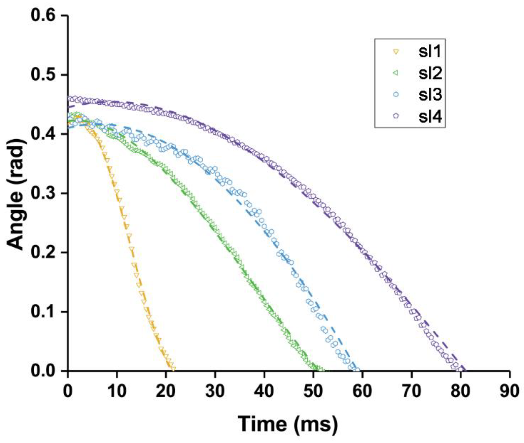
Figure 5.
Angle changes with panel angle θs variation. When the angle between the two panels increases, the angles of motion are changed because the radius of the motion is decreased.
Figure 5.
Angle changes with panel angle θs variation. When the angle between the two panels increases, the angles of motion are changed because the radius of the motion is decreased.

Figure 6.
Angle changes with panel rotation axis position xp variation. (a) Positions of rotational axis are marked with number. The number ③ is center of the two panels. (b) The angles of motion are tracked in real time owing to the position of the changes in the driving shaft.
Figure 6.
Angle changes with panel rotation axis position xp variation. (a) Positions of rotational axis are marked with number. The number ③ is center of the two panels. (b) The angles of motion are tracked in real time owing to the position of the changes in the driving shaft.
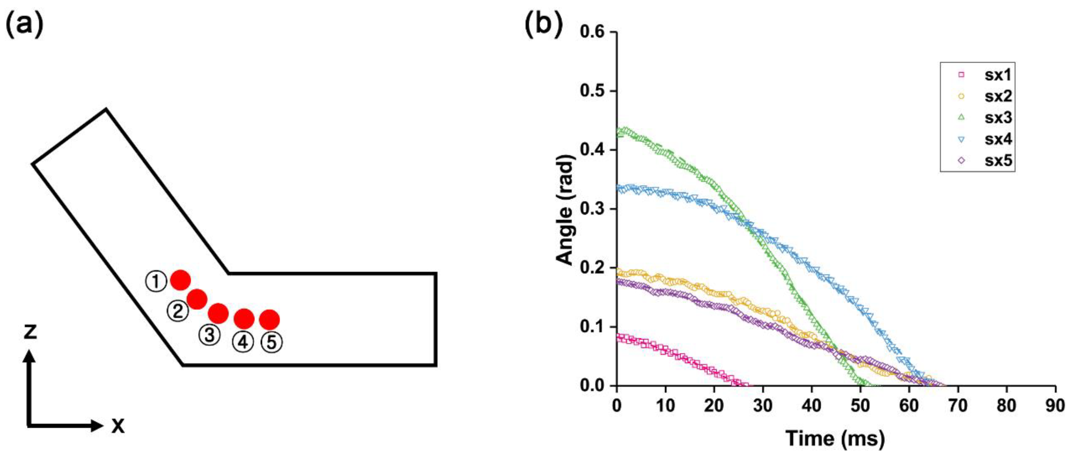
Figure 7.
A schematic diagram for mathematical modeling.

Figure 8.
Experimental and theoretical data fitting graphs. The actual angular changes tracked at 0.5 ms intervals and fitting line (dash line). The theoretical model and previous model are also depicted as graphs. For correcting error, restoring energy with constant k also considered (dash-dot line).


Table 1.
Experimental data of sl2.
| Symbol | Definition | Value |
|---|---|---|
| ε0 | Electric permittivity of free space | 8.85 × 10⁻¹² F/m |
| ΔV | Voltage difference | 5 kV |
| z0 | Gap between the bottom and the V-shaped actuator | 1 × 10⁻³ m |
| a | Length of panel | 5 × 10⁻³ m |
| mt | Mass of panel | 0.43 × 10⁻³ kg |
| g | Gravitational force | 9.80 m/s2 |
| h | Thickness of panel | 3 × 10⁻³ m |
| dcom | Distance between the center of mass and position of rotational axis in x-direction | 1.43 × 10⁻³ m |
| θs | Angle between two panel | 2.09 rad |
| x1 | The orthogonal length of the electrostatic attraction | 7 × 10⁻³ m |
| y1 | Width of panel in y-axis | 10 × 10−3 m |
© 2018 by the authors. Licensee MDPI, Basel, Switzerland. This article is an open access article distributed under the terms and conditions of the Creative Commons Attribution (CC BY) license (http://creativecommons.org/licenses/by/4.0/).
Share and Cite
MDPI and ACS Style
Song, K.; Lee, H.; Cha, Y. A V-Shaped Actuator Utilizing Electrostatic Force. Actuators 2018, 7, 30. https://doi.org/10.3390/act7020030
AMA Style
Song K, Lee H, Cha Y. A V-Shaped Actuator Utilizing Electrostatic Force. Actuators. 2018; 7(2):30. https://doi.org/10.3390/act7020030
Chicago/Turabian StyleSong, Kahye, Hyeongyu Lee, and Youngsu Cha. 2018. "A V-Shaped Actuator Utilizing Electrostatic Force" Actuators 7, no. 2: 30. https://doi.org/10.3390/act7020030
Note that from the first issue of 2016, this journal uses article numbers instead of page numbers. See further details here.