Article

Lateral Vibration Suppression by Varying Stiffness Control in a Vertically Active Magnetic Suspension System

Department of Mechanical Engineering, Saitama University, Shimo okubo 255, Sakura-ku, Saitama 338-8570, Japan
*
Author to whom correspondence should be addressed.
Actuators 2018, 7(2), 21; https://doi.org/10.3390/act7020021
Submission received: 22 March 2018 / Revised: 20 April 2018 / Accepted: 27 April 2018 / Published: 10 May 2018
(This article belongs to the Special Issue Magnetic Bearing Actuators)

Abstract

:
Reduction of vibration in passively supported lateral directions by varying stiffness control is discussed in a vertically active magnetic suspension system. In the target system, one pair of electromagnets is arranged in differential driving mode to actively control the vertical motion of the floator. Usually the floator is prone to vibrate in the lateral direction because it is passively supported by virtue of the edge effect of the electromagnets. In this work, such vibrations are reduced by incrementing or decrementing the currents simultaneously during vibration without changing the vertical position of the floator. This control strategy is implemented in a developed apparatus where an iron ball is suspended by differentially operated electromagnets without any mechanical contact. Experiments are carried out, and the results show the reduction of lateral vibrations without changing the vertical position of the floator.

1. Introduction

Vibration causes oscillation, which may be detrimental to a system. Vibration control systems can be divided into passive, active, and semi-active, depending on the external power required. Though active vibration control systems can act upon broadband load and frequency, they require a large control effort associated with the system [1]. Moreover, in multiple-degree-of-freedom systems, the actuators and sensors make the control system complex and bulky. This causes problems in some applications, such as magnetic bearings. Reducing the actively controlled degree-of-freedom can lead to miniaturization of the system [2]. In a vertically active magnetic suspension system operated in the differential mode, vibration is easily induced in the lightly damped lateral directions. Any disturbance in lateral directions can cause the system to oscillate for a long time. Vibration can be suppressed in such systems by varying stiffness, as mentioned in Mizuno et al. [3] and Javed et al. [4]. Varying stiffness control was applied in a single-degree-of-freedom system in both cases.
In a magnetic suspension system, when five degrees-of-freedom (DoF) are actively controlled, it achieves high reliability and high stiffness [5]. Various control strategies can be applied to active magnetic suspension systems, such as PID (proportional-integral-derivative) control [6] and robust control [7,8,9], to reduce vibration. Robust control can be applied by considering the uncertainties of a magnetic bearing system, such as linearization error, parameter uncertainty, and gyroscopic effect [10]. Standard control methods may not deal with all factors [7]. Zhou et al. [9] applied µ synthesis to active magnetic bearing system considering parametric uncertainty. Two radial magnetic bearings are used in their system. Gosiewski et al. [8] designed an H-infinity robust controller. They compared the proposed controller with a PID controller and reported better performance. In their system, two pairs of coils are placed in each direction with a permanent magnet (PM) in the rotor. The performance of the robust control system depends on the proper selection of the weighting function [8]. The control systems used in [8,9] show good performance; however, the design of the systems is complex. In addition, all of them were for actively controlled DoF. Asama et al. [6] developed a 5-axis actively controlled bearingless PM motor. The axial direction is controlled by thrust magnetic bearing. The radial and tilting motions of the rotor are controlled actively by two bearingless motor units. However, to reduce the size and cost, the actively controlled directions can be reduced. When the radial directions are actively controlled, and the axial and tilting directions are passively stabilized, vibration can be induced easily in these directions. Rao et al. [11] proposed a permanent free bearingless motor where the radial directions are actively controlled. Axial and tilting directions are passively stabilized by the bias and control fluxes. In their system, the bias current is high in order to create the bias flux. Sugimoto et al. [5] proposed increasing the damping effect in the axial direction to suppress vibration in two-axis actively controlled bearingless PM motors. In their system, axial displacement of the rotor is measured based on the variation in flux linkage. However, the proposed estimation method and vibration suppression technique are effective for PM bearingless motors. For further reduction of space and cost, a 1-axis actively controlled magnetic bearing [2] and a bearingless motor [12] were investigated. In these systems, the axial direction is actively controlled, and the radial and tilting directions are passively controlled. However, the precision machining of the parts is necessary to maintain passive stiffness to facilitate vibration reduction in passively stable radial and tilting vibration [2]. Applying varying stiffness control requires radial displacement, so different sensing techniques may require miniaturization of the system when applied to these systems.
Varying stiffness control has been studied in order to control vibration by various researchers. Winthrop et al. [13] gathered data related to various variable stiffness devices and introduced two parameters for comparing the characteristics of those devices. Ledezma-Ramirez et al. [14] reduced the shock acting on the base of a single-degree-of-freedom system by switching the stiffness strategy. The control in the system was divided into two stages: low stiffness was maintained during shock, and switching stiffness control was applied to suppress the residual vibration. A similar type of set up was used in [15]. Zhou et al. [15] developed a tunable vibration isolator with a mechanical spring and electromagnets, and permanent magnets, which possesses high-static-low-dynamic properties. The isolator works passively or semi-actively and suppresses base vibration. The authors of [14] used nylon wires to attach the floator to the frame, and in [15], a steel beam supported the isolated mass. Most existing methods, some of which are mentioned in [6,8,9], including switching stiffness control [14], target the vibration in the normal direction—that is, the direction of force produced by an actuator. This indicates that the number of actuators increases in proportion to the number of degrees-of-freedom to be controlled. In contrast, in the proposed system, two electromagnets (actuators) in the normal direction are used to reduce the vibration in the lateral directions (2-DoF) without any added actuator. In magnetic suspension system, two such electromagnets are commonly used to control 1-DoF motion to generate bidirectional force, as the force of an electromagnet is unidirectional (attractive). The proposed method utilizes this configuration. The motion in the normal direction is not affected, even if switching stiffness control is introduced. This is the main advantage of the proposed method. The only parameter that must be calculated correctly is the current-force coefficient to avoid such interaction. The basic idea of the proposed method was reported in [3]. Mizuno et al. [3] reported vibration reduction by switching stiffness in an active magnetic suspension system. In addition, a modified control strategy was introduced in their report. Varying stiffness in attenuating lateral vibration was experimented in a single-degree-of-freedom system in Javed et al. [4]. A different procedure was applied to estimate the displacement of the floator. However, single-degree-of-freedom was considered to apply stiffness control in these systems [3,4]. As for magnetic suspension, the floator was supported with auxiliary mechanical means. Therefore, it is necessary to evaluate the performance of the strategy on a freely suspended floator to find out its interaction with vertical motion. The controller is adjustable by the control current in both of the mentioned strategies and additionally by the steepness parameter in the modified control strategy.
In this paper, a pair of electromagnets positioned in differential mode are used to actively control the vertical direction, as well as to reduce vibration in the lateral directions in a three-degrees-of-freedom (3-DoF) system. The floator is suspended freely without any mechanical support. Varying stiffness control is applied to reduce lateral vibration, maintaining the desired vertical position. This control strategy may be utilized to reduce actively controlled directions and to attenuate vibration.

2. Principle of Suspension and Stiffness Control

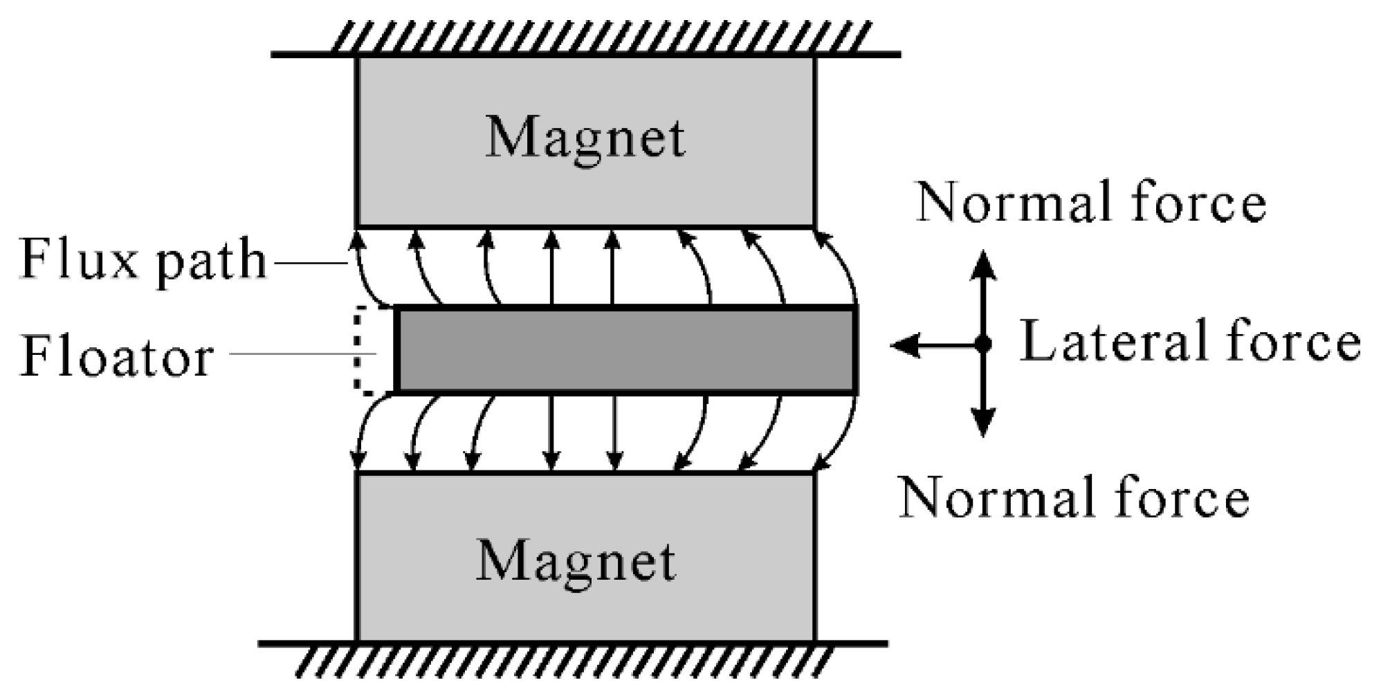
When a ferromagnetic material is placed in a magnetic field, the flux passes through it. When it is moved from its position, a force on the material is realized. The force tries to shorten the flux path, and the flux passes through the path of least reluctance [16]. This phenomenon is named the edge effect, and is shown in Figure 1. The forces acting on the moving floator in vertical and horizontal directions are normal and lateral forces, respectively. The lateral forces act to restore the equilibrium position.
The control system can be divided into two stages: (a) suspension of the floator, and (b) application of stiffness control. Both of these are discussed below.

2.1. Suspension of the Floator

In a magnetic suspension system, a controller delivers a control signal based on the difference between the reference and the position of floator measured by sensor. This control signal is fed into a power amplifier to transform it into control current, which is supplied to electromagnets. Proportional-derivative (PD) and PID are commonly used controllers in a magnetic suspension system. Steady-state error occurs in applying PD control. It can be overcome by using PID control integrating feedback [17].
In the developed system, both of the controls are applied. PID control is applied in the Z-direction of the floator to achieve suspension while varying stiffness control. The gains of the PID controller are determined experimentally through trial and error. At first, PD control is applied to achieve stable levitation, and afterward, the integral control is added to maintain the desired position. Moreover, PD control is applied to determine the properties of the system. The position of the floator is almost in the middle of the two electromagnets in the Z-direction. Permanent magnets are used in both the upper and lower electromagnets to provide bias flux. This lessens the bias current, a high value of which could increase the temperature of the coil of the electromagnets. This bias flux ensures the linearity of control current in the working range.

2.2. Application of Stiffness Control

The equation of motion of a single-degree-of-freedom (sdof) system as shown in Figure 2a can be written as follows:
m d ¨ ( t ) + k d ( t ) = 0 ,
where m is mass, k is the effective stiffness of the system, and d(t) is displacement with respect to time.
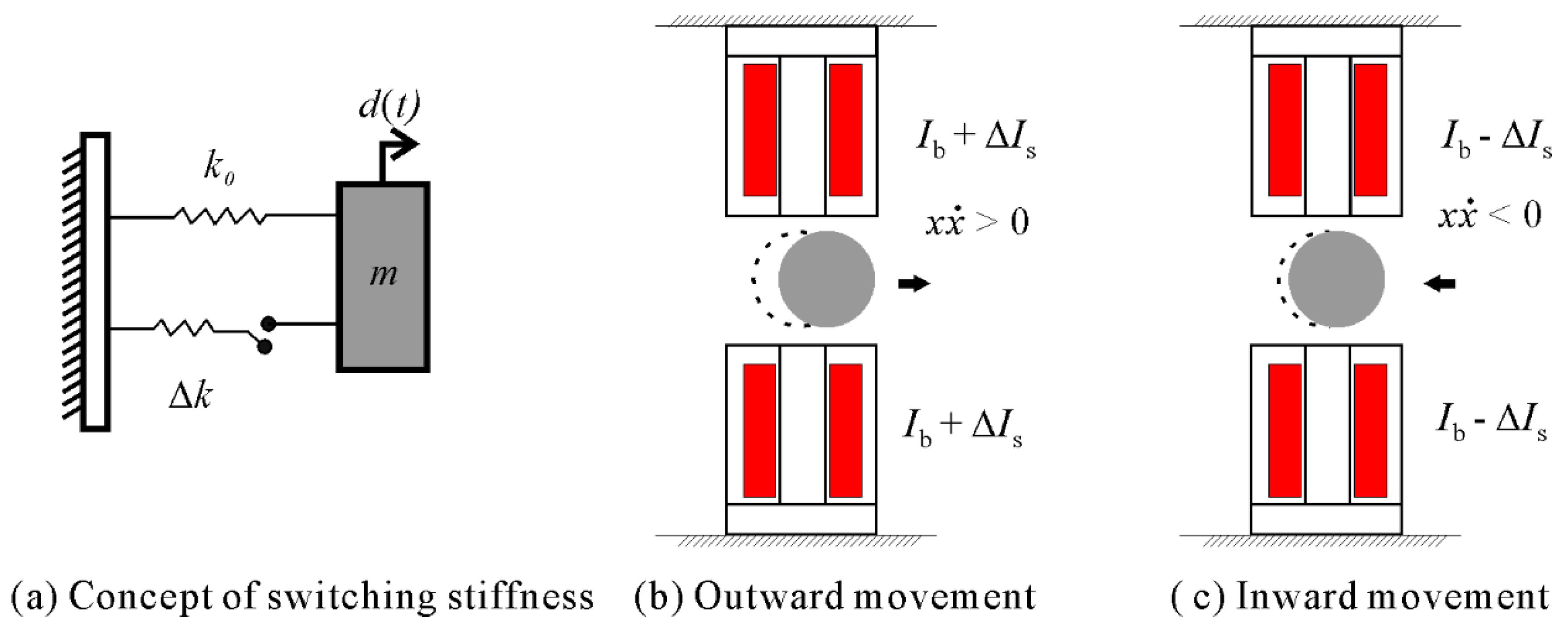
In the case of switching stiffness control, the stiffness of the system can be changed between high and low depending on the product of displacement, d ( t ) and velocity, d ˙ ( t ) of the floator as mentioned in Equation (2) [3]:
k =   { k 0 +   k d d ˙ > 0 k 0 d d ˙ < 0 .
In a magnetic suspension system, the effective stiffness in the lateral direction is adjusted by varying the bias current of the electromagnets. As written in Equation (3) and depicted in Figure 2b,c, to attain a high stiffness state when x x ˙ > 0 , the switching current, ∆Is, is added to the bias current, Ib. When x x ˙ < 0 the switching current is subtracted from bias current to achieve a low stiffness state.
I =   { I b + I s x x ˙ > 0 I b x x ˙ = 0 I b I s x x ˙ < 0 ,
where x and x ˙ 
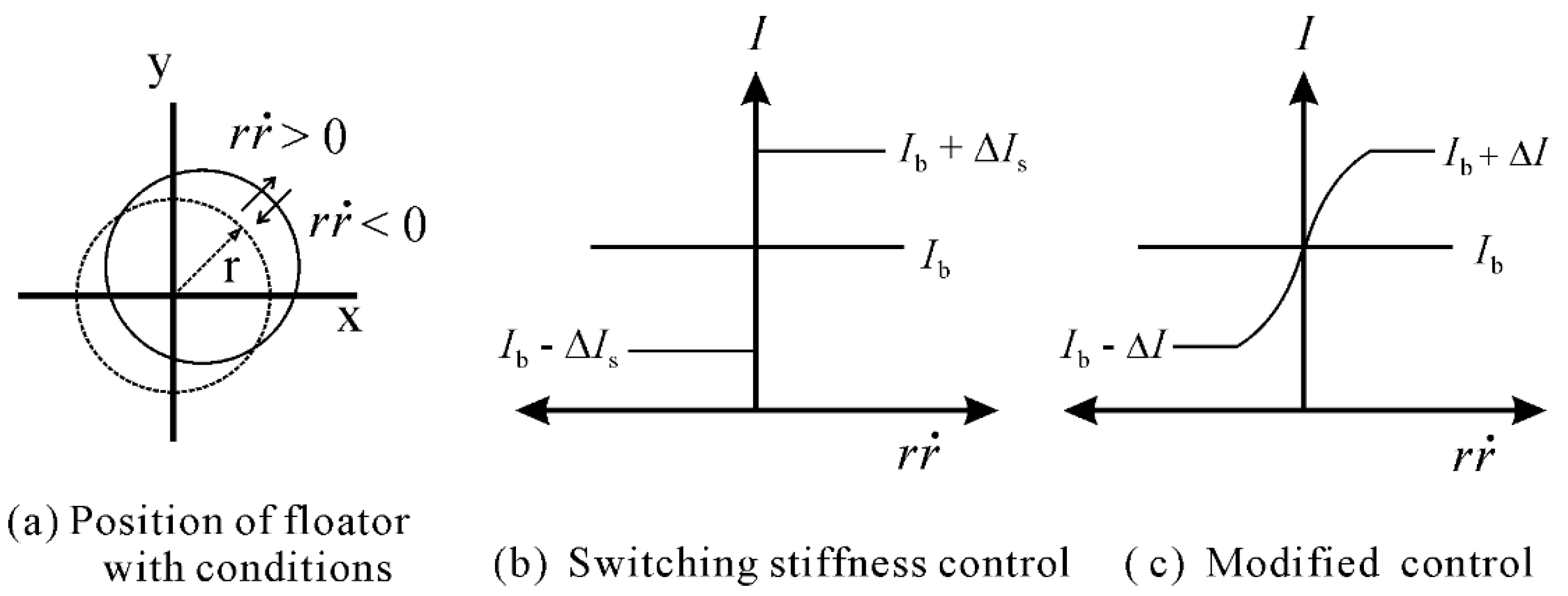
are displacement and velocity with respect to time, respectively. In brief, when the floator is moving out from its equilibrium position, the stiffness is increased, and when moving in to its equilibrium position, the stiffness is decreased. As the stiffness control is intended to apply in a 3-DoF system to reduce lateral vibration, the distance r of the floator from the reference position is measured as
r 2 =   x 2 + y 2 ,
where x and y are the displacements in X- and Y-directions, respectively. Figure 3a shows the conditions with position of floator. Therefore, the Equation (3) becomes
I =   { I b + I s r r ˙ > 0 I b r r ˙ = 0 I b I s r r ˙ < 0 .
Another approach to varying the stiffness of a system is mentioned in Mizuno et al. [3]. An inverse tangent function is introduced in the control current, as shown in Equation (6), to smooth the profile of ∆I.
I = I b +   I 2 π tan 1 ( q r r ˙ ) ,
where ∆I is the control current and q is the parameter to change the steepness of the control current. When q is increased, the shape of the control current becomes the same as that of the control current of the switching stiffness strategy. This control strategy is referred to as modified stiffness control. The current with respect to r r ˙ is depicted in Figure 3b,c for both control strategies [4].
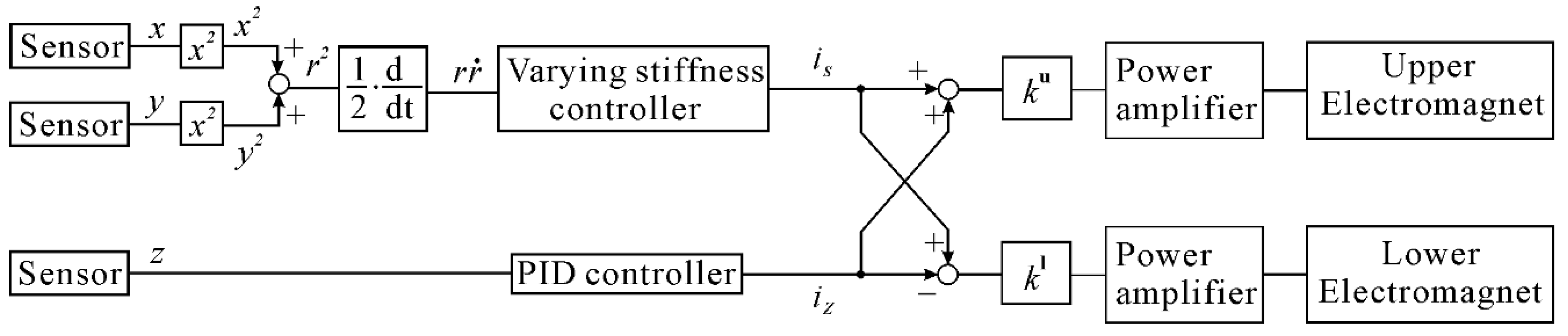
Modal control is applied to distribute the current between the upper and lower electromagnets. Figure 4 shows the block diagram of modal control. ku and kl are the gains of upper and lower electromagnets, respectively, to balance the force in the Z-direction during stiffness control, iz is the control current to levitate the floator, and is is the control current to reduce lateral vibration. A filtered derivative is used for differentiation of the signal in the controller, which is realized by digital signal processor (DS1005) with a sampling frequency of 10 kHz. A low-pass filter with a cut-off frequency of 100 Hz is used, which is considered high enough compared to the frequency in the lateral directions. The time delay does not affect the stability in the lateral directions. This is considered to be below the maximum limit, as Ledezma-Ramirez et al. [21] mentioned in their study that too much time delay could make the system unstable.

3. Configuration of Experimental Apparatus

To suppress lateral vibration of the floator by varying stiffness control, a three-degree-of-freedom magnetic suspension system is developed. Figure 5a shows the schematic drawing, and Figure 5b shows the photograph of the developed system. The core of upper and lower electromagnets (EMs) and voice coil motor (VCM) are made of soft iron. The floator is an iron ball with a diameter of 25 mm and a mass of 63.9 g. In both electromagnets, permanent magnets are used, and the number of turns of the coil are the same. The size of the upper permanent magnet is larger than the lower permanent magnet, in order to produce a large force in the upper direction. This is done to reduce the bias current of the upper EM. An optical sensor is fabricated to measure displacement in three directions. The sensor consists of two units, each placed on two sides of the floator in the Y-direction. Each unit has a light emitting diode, and four plano-convex lenses, which focus light to four phototransistors. When the ball moves in any direction, the light falling on the lenses changes [18]. As a result, the voltage across the phototransistor varies. The circuit is designed such that when light falls on the phototransistors, the voltage across it will increase. The voltage will decrease in the shadow region. Calibration is performed to estimate displacement of the ball in each direction with the voltages obtained from the eight phototransistors. A VCM with internal linear bearing is installed in the X-direction to produce disturbance. The shaft of the VCM is selected to strike the ball in such a way that it does not affect the estimation of the position of the ball by creating shadow on lenses.

4. Parameter Identification

Though the number of turns of the coil of the upper and lower electromagnets is the same, the strengths of the permanent magnets are different. To balance the force during the change of current in varying stiffness control, the current-force coefficients of both electromagnets (EMs) are necessary to determine. Otherwise, vibration will be induced in the Z-direction. This can be realized by considering linear current-force and gap-force coefficient of the electromagnets based on the equation of motion in the Z-direction given by Equation (7). The first two terms come from the upper EM denoted by subscript u, and the last two terms come from lower EM denoted by subscript l.
m z ¨ =   k i u i +   k z u z k i l i + k z l z ,
where m is mass of the ball, kiu is the current-force coefficient of the upper EM (EMu), kzu is the gap-force coefficient of the EMu and permanent magnet, kil is the current-force coefficient of the lower EM (EMl), kzl is the gap-force coefficient of the EMl and permanent magnet, i is the control current, and z is the displacement in Z-direction.
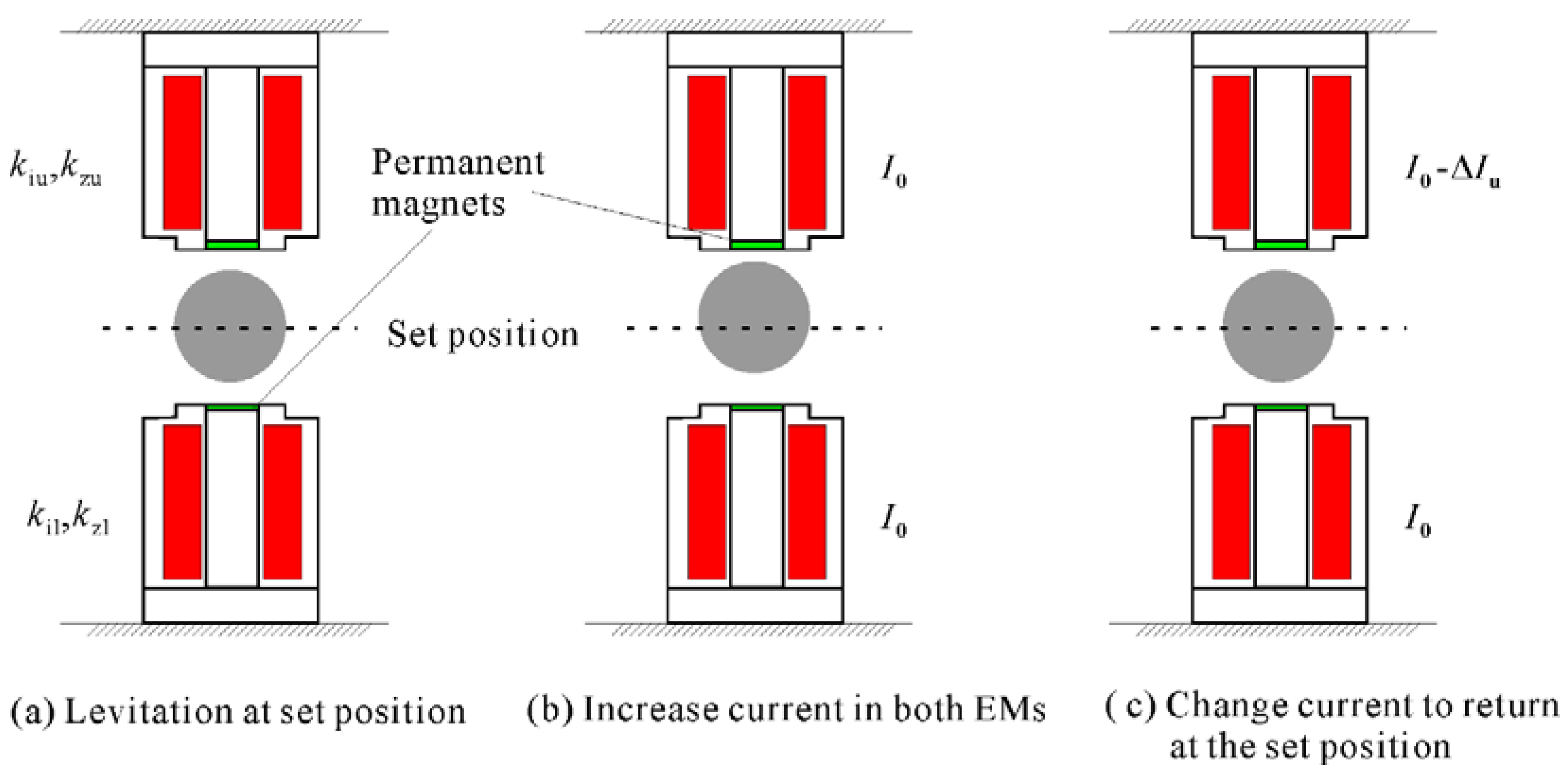
As the value of kzu is larger than the kzl, it is necessary to find out the current-force coefficients of the electromagnets to balance the force of EMu and EMl during control. To find out the ratio of current-force coefficients, at first, the ball is levitated at the set position by PD control, as shown in Figure 6a. The same amount of current I0 is added to both EMs. The EMu generates larger force than the EMl, as a result, the ball moves upward as shown in Figure 6b. Either current should be decreased in the EMu or increased in the EMl to return the ball to its set position. The procedure is depicted with decreasing the current in EMu in Figure 6.
The force is balanced at this set position, and the relation can be written as follows:
k i u k i l =   I 0 ( I 0   I u )   > 1 ,
where I0 is the current added to both EMs, ∆Iu is the current reduced from EMu to return the ball to the set position.
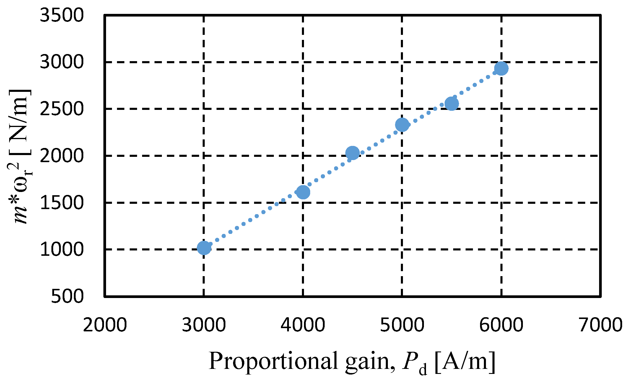
In the developed device
k i u k i l = 1.76 .
The total ki of the system is measured by plotting mω2 versus proportional gain, Pd of the PD controller [19].
ω r 2 =   ( k i u +   k i l ) P d k s m ,
where m is the mass of the ball, ωr is resonant angular frequency of the system in rad/s, and ks = kzu + kzl is gap-force coefficient of the system. The slope of the curve represents the total current-force coefficient of the system. From Figure 7, it is found that
k i u +   k i l =   0.636   N / A .
From Equations (9) and (11) it is found that kiu = 0.405 N/A and kil = 0.23 N/A.
According to the findings, 0.23 N/A and 0.405 N/A are assigned as the gain in EMu and EMl, respectively, to balance the force as written in Equation (12).
k u k l =   k i l k i u ,
where ku and kl are gains of upper and lower electromagnets, respectively, to balance force in Z-direction.
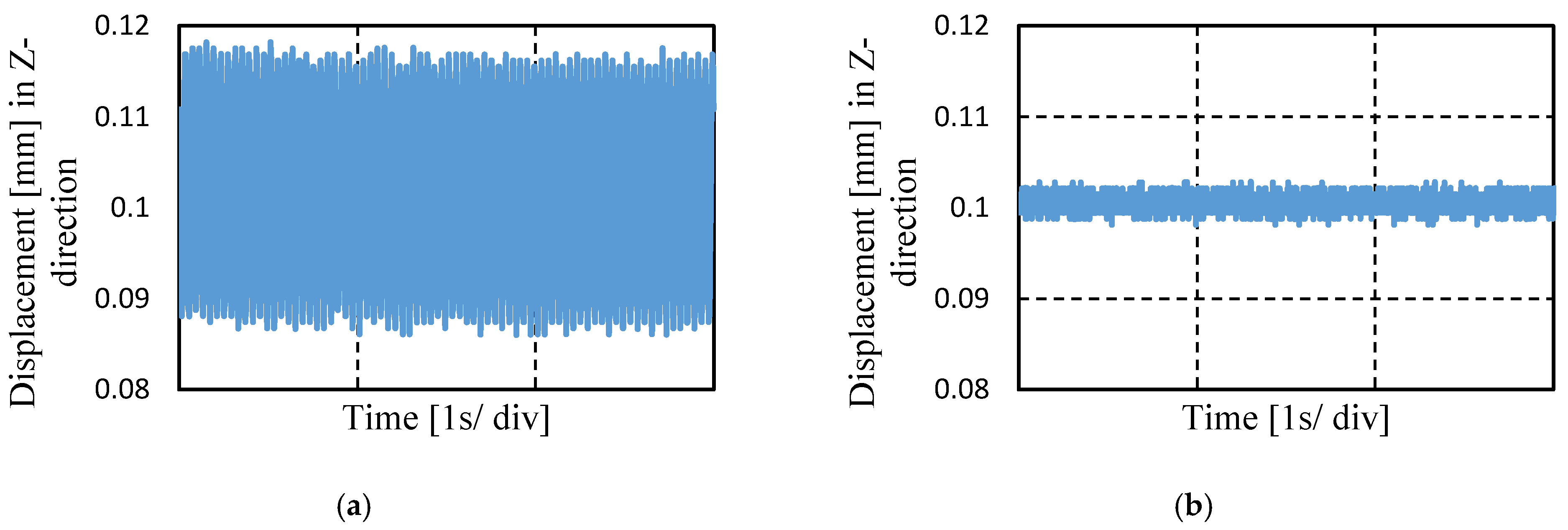
However, it has been found out that the permanent magnets get heated when control is applied. This may occur because of the large amplitude of control current that flows through the coils during control. As a result, the values are reduced to almost half of these values without affecting the balance of force.
Figure 8 shows that if balance of force is not attained, vibration occurs in the Z-direction. At first, PID control is applied, and the ball is levitated at set point 0.1 mm. Both of the EMs are assigned with the same gains, and switching stiffness control is applied with switching current, ∆Is = 0.1 A. Due to the imbalance of force the ball moves in Z-direction with maximum amplitude of 0.03 mm, as shown in Figure 8a. However, when the correct gain is assigned in both EMs, the amplitude of displacement reduces to 0.005 mm.

5. Experimental Results

Both the switching stiffness control and modified stiffness control are applied to suppress the lateral vibration. Impulse force is generated by the voice coil motor as disturbance to the floator. The controller is realized by a digital signal processor (DS1005). Two bipolar analogue amplifiers (Takasago, LTD., Tokyo, Japan, BPS40-15) are used for the electromagnets. The cut-off frequency is 10 kHz. Maximum voltage is 40 V, and maximum current is 15 A. The experimental results are summarized as follows:

5.1. Applying Switching Stiffness Control

Figure 9 shows the displacement of the floator in three directions with respect to time while switching stiffness control is applied to the lateral directions (the X- and Y-directions), and PID control is applied in the Z-direction. When the VCM strikes the ball, it moves further than the new position of the pole of VCM. The ball returns immediately, and touches the shaft of VCM. Afterward, the shaft of VCM is pulled back, and vibration induced in different directions. For switching current 0.1 A and 0.2 A, it is found that the settling time is reduced by increasing the control current. In X-direction it is decreased from 3.1 s to 1.64 s and in Y-direction from 3.22 s to 1.72 s. There may have some inclination in the shaft of VCM. As a result, lateral disturbance induces vibration in the Z-direction, which attenuates with time, as shown in Figure 9. The time history can be divided into two parts. In the first part, the ball is actively suspended, and no disturbance is introduced. The switching stiffness control is working as well. In the second part, disturbance is introduced by VCM, as indicated in Figure 9a, and the vibration is reduced by the stiffness control. Table 1 shows the settling times in the lateral directions with respect to different switching currents in switching stiffness control. The switching stiffness control can attenuate lateral vibration, and increasing the control current reduces the settling time.

5.2. Applying Modified Stiffness Control

To investigate the effect of control current, ∆I, with inverse tangent, several experiments are carried out. Firstly, effect of control current with the same value of q on settling times of lateral directions is determined as shown in Figure 10. Secondly, the effect of the parameter q with different values for the same control current on settling times is determined, as shown in Figure 11. Figure 10 shows displacements with respect to time for (a) control current, ∆I = 0.1 A and (b) control current, ∆I = 0.2 A, both with a value of q = 10. In the case of control current 0.1 A, the settling times are 2.44 s and 2.47 s for the X- and Y-directions, respectively. With the increase in control current to 0.2 A, the settling times decrease, becoming 1.06 s and 1.42 s for the X- and Y-directions, respectively. Figure 10a and Figure 11 show that for control current 0.1 A with increasing values of q of 10, 30, and 70, the settling times decrease. For example, the settling times in the X-direction for values of q = 10, 30, and 70 are 2.44 s, 1.95 s, and 1.55 s, respectively. As a result, it can be said that control current with inverse tangent can attenuate vibration in the lateral direction in the tested magnetic suspension system.
It is observed from the above mentioned results that the settling time while applying switching stiffness control is longer than the modified stiffness control. The reason may be the presence of noise in the displacement signal as the changing of control current depends on r r ˙ . It was reported in Mizuno et al. [20] that presence of noise may increase the settling time while applying switching stiffness control. There will be switching of current in inappropriate time due to noise. Ledezma-Ramirez et al. [21] mentioned from their simulated results that improper timing of changing stiffness in switching stiffness control may reduce the performance of the system.
In contrast, when applying the modified stiffness control, the effect of noise may be reduced, as the amplitude of current change depends on r r ˙ . When r r ˙ decreases, ∆I also decreases, unlike in switching stiffness control. As a result, the stiffness change in improper time may have a smaller effect on settling time. This may be inferred to be the reason behind the reduced settling time in the case of modified controller in comparison to the switching stiffness strategy.

6. Conclusions

A device was developed to apply the switching stiffness control and modified stiffness control to change the stiffness in a 3-DoF magnetic suspension system. It has been found that both strategies are able to attenuate lateral vibrations without electromagnets in those directions. This leads to cost reduction and downsizing of the system. The settling time depends on the amount of control current applied to the electromagnets. Increase in control current reduces the settling time. Moreover, the parameter defining the steepness in varying stiffness function plays a role in the modified control strategy. The same value of the control current with an increase in that parameter can reduce the settling time. It is inferred that the presence of noise in the signal causes a large settling time when switching stiffness control is applied. In this situation, modified stiffness control is able to perform better. One of the key points is to measure the correct current-force coefficients of the electromagnets. Otherwise, it will create vibration in the normal direction. In future, the frequency response of the system and other features like energy dissipation during control will be investigated.

Author Contributions

A.J. and T.M. wrote the paper, M.T. contributed in fabrication of the electric circuits, Y.I. contributed in designing the experimental device, A.J. conducted the experiments, M.H. and D.Y. contributed through analyzing the data.

Acknowledgments

This research was partially supported by the Matching Planner Program (MP2721566788) from Japan Science and Technology Agency, JST.

Conflicts of Interest

The authors declare no conflict of interest. The funding sponsors had no role in the design of the study, in the collection, analyses, or interpretation of data, in writing of the manuscript, and in the decision to publish the results.

References

  1. Jalili, N. A comparative study and analysis of semi-active vibration-control systems. J. Vib. Acoust. Trans. ASME 2002, 124, 593–605. [Google Scholar] [CrossRef]
  2. Kuroki, J.; Shinshi, T.; Li, L.; Shimokohbe, A. Miniaturization of a one-axis-controlled magnetic bearing. Precis. Eng. 2005, 29, 208–218. [Google Scholar] [CrossRef]
  3. Mizuno, T.; Tanabu, J.; Ishino, Y.; Takasaki, M. Lateral vibration control in attractive magnetic suspension system (2nd report: Experimental study on the lateral vibration control). In Proceedings of the 14th Symposium on Motion and Vibration Control, Tochigi, Japan, 22–24 June 2015; pp. 281–284. (In Japanese). [Google Scholar]
  4. Javed, A.; Mizuno, T.; Takasaki, M.; Ishino, Y.; Hara, M.; Yamaguchi, D. Proposal of lateral vibration control based on force detection in magnetic suspension system. Int. J. Appl. Electromagn. Mech. 2016, 52, 223–229. [Google Scholar] [CrossRef]
  5. Sugimoto, H.; Miyoshi, M.; Chiba, A. Axial vibration suppression by field flux regulation in two-axis actively positioned permanent magnet bearingless motors with axial position estimation. IEEE Trans. Ind. Appl. 2018, 54, 1264–1272. [Google Scholar] [CrossRef]
  6. Asama, J.; Amada, M.; Miyamoto, N.; Chiba, A.; Iwasaki, S.; Takemoto, M.; Fukao, T.; Rahman, M.A. Evaluation of a bearingless PM motor with wide magnetic gap. IEEE Trans. Energy Convers. 2010, 25, 957–964. [Google Scholar] [CrossRef]
  7. Gosiewski, Z.; Mystkowski, A. The robust control of magnetic bearings for rotating machinery. Solid State Phenom. 2006, 113, 125–130. [Google Scholar] [CrossRef]
  8. Gosiewski, Z.; Mystkowski, A. Robust control of active magnetic suspension: Analytical and experimental results. Mech. Syst. Signal Process. 2008, 22, 1297–1303. [Google Scholar] [CrossRef]
  9. Zhou, J.; Zheng, S.; Han, B. Application of mu systhesis to the control of active magnetic bearings with parametric uncertainty. In Proceedings of the IEEE 20th International Conference on Electrical Machines and Systems (ICEMS), Sydney, Australia, 11–14 August 2017. [Google Scholar] [CrossRef]
  10. Namerikawa, T.; Fujita, M. Robust performance analysis of magnetic bearings. IEEJ Trans. Ind. Appl. 2001, 121, 1061–1067. [Google Scholar] [CrossRef]
  11. Rao, J.; Hijikata, W.; Shinshi, T. A bearingless motor utilizing a permanent magnet free structure for disposable centrifugal blood pump. J. Adv. Mech. Des. Syst. Manuf. 2015, 9. [Google Scholar] [CrossRef]
  12. Sugimoto, H.; Tanaka, S.; Chiba, A. Reduction of rotor vibration in passively stabilized direction in single-drive bearingless motor. In Proceedings of the 14th International Symposium on Magnetic Bearings, Linz, Austria, 11–14 August 2014; pp. 127–131. [Google Scholar]
  13. Winthrop, M.F.; Baker, W.P.; Coob, R.G. A variable stiffness device selection and design tool for lightly damped structures. J. Sound Vib. 2005, 287, 667–682. [Google Scholar] [CrossRef]
  14. Ledezma-Ramirez, D.F.; Ferguson, N.S.; Brennam, M.J. An experimental switchable stiffness device for shock isolation. J. Sound Vib. 2012, 331, 4987–5001. [Google Scholar] [CrossRef]
  15. Zhou, N.; Liu, K. A tunable high-static-low-dynamic stiffness vibration isolator. J. Sound Vib. 2010, 329, 1254–1273. [Google Scholar] [CrossRef]
  16. Boldea, I.; Naser, S.A. Linear Electric Actuators and Generators; Cambridge University Press: Cambridge, UK, 1997; p. 27. ISBN 978-0521020329. [Google Scholar]
  17. Bleuler, H.; Cole, M.; Keogh, P.S.; Larsonneur, R.; Maslen, E.H.; Nordmann, R.; Okada, Y.; Schweitzer, G.; Traxler, A. Magnetic Bearings; Schweitzer, G., Maslen, E.H., Eds.; Springer: Berlin, Germany, 2009; ISBN 978-3-642-00496-4. [Google Scholar]
  18. Mizuno, T.; Sakai, Y.; Takasaki, M.; Ishino, Y. Development of a wind-tunnel for spinning body using magnetic suspension. Trans. JSME 2017, 83. (In Japanese) [Google Scholar] [CrossRef]
  19. Ishino, Y.; Mizuno, T.; Takasaki, M.; Hara, M.; Yamaguchi, D. Development of a compact axial active magnetic bearing with a function of two-tilt-motion control. Actuators 2017, 6, 14. [Google Scholar] [CrossRef]
  20. Mizuno, T.; Tanabu, J.; Ishino, Y.; Takasaki, M. Lateral vibration control in attractive magnetic suspension system. Trans. JSME 2017, 83. (In Japanese) [Google Scholar] [CrossRef]
  21. Ledezma-Ramirez, D.F.; Ferguson, N.S.; Brennam, M.J. On the instabilities in a switchable stiffness system for vibration control. Int. J. Acoust. Vib. 2016, 21, 75–80. [Google Scholar] [CrossRef]
Figure 1. Concept of edge effect.
Actuators 07 00021 g001
Figure 2. Switching stiffness in magnetic suspension system: (a) switching stiffness in sdof system; (b,c) currents in electromagnets for different conditions.
Actuators 07 00021 g002
Figure 3. (a) Radial position with conditions, and profile of current: (b) switching stiffness control; (c) modified control.
Actuators 07 00021 g003
Figure 4. Block diagram of modal control.
Actuators 07 00021 g004
Figure 5. Developed three-degree-of-freedom experimental system: (a) schematic drawing; (b) photograph of the device.
Actuators 07 00021 g005
Figure 6. Finding the relationship between current-force coefficients: (a) levitation at set position; (b) increase of current in both EMs; (c) reduction of current from EMu.
Actuators 07 00021 g006
Figure 7. Relationship between stiffness of the system to the proportional gain. Dots: data points and dotted line: linear regression line.
Actuators 07 00021 g007
Figure 8. Effect of balancing the forces on floator position in Z-direction: (a) vibration occurs due to unbalanced force; (b) vibration reduced by assigning proper gains of EMs.
Actuators 07 00021 g008
Figure 9. Applying switching stiffness control to reduce lateral vibration with (a) switching current ∆Is = 0.1 A and (b) switching current ∆Is = 0.2 A.
Actuators 07 00021 g009
Figure 10. Lateral vibration reduction by applying modified stiffness control with same value of q = 10, (a) control current, ∆I = 0.1 A and (b) control current, ∆I = 0.2 A.
Actuators 07 00021 g010
Figure 11. Effect of parameter q on settling time with the same control current, ∆I = 0.1 A, (a) q = 30 and (b) q = 70.
Actuators 07 00021 g011
Table 1. Settling time in lateral directions with different switching currents.
Switching Current, ∆Is [A] Settling Time [s]
X-DirectionY-Direction
0.13.13.22
0.151.992.19
0.21.641.72

