Levitating Micro-Actuators: A Review


1
The Institute of Microstructure Technology, Karlsruhe Institute of Technology, Hermann-von-Helmholtz-Platz 1, 76344 Eggenstein-Leopoldshafen, Germany
2
Voxalytic GmbH, Rosengarten 3, 76228 Karlsruhe, Germany
*
Author to whom correspondence should be addressed.
Actuators 2018, 7(2), 17; https://doi.org/10.3390/act7020017
Submission received: 27 February 2018
/
Revised: 27 March 2018
/
Accepted: 4 April 2018
/
Published: 9 April 2018
Abstract
:Through remote forces, levitating micro-actuators completely eliminate mechanical attachment between the stationary and moving parts of a micro-actuator, thus providing a fundamental solution to overcoming the domination of friction over inertial forces at the micro-scale. Eliminating the usual mechanical constraints promises micro-actuators with increased operational capabilities and low dissipation energy. Further reduction of friction and hence dissipation by means of vacuum leads to dramatic increases of performance when compared to mechanically tethered counterparts. In order to efficiently employ the benefits provided by levitation, micro-actuators are classified according to their physical principles as well as by their combinations. Different operating principles, structures, materials and fabrication methods are considered. A detailed analysis of the significant achievements in the technology of micro-optics, micro-magnets and micro-coil fabrication, along with the development of new magnetic materials during recent decades, which has driven the creation of new application domains for levitating micro-actuators is performed.
1. Introduction
Micro-Electro-Mechanical Systems (MEMS) have been used in an ever-increasing number of applications due to the remarkable progress in the processing of silicon as a traditional mechanical material for MEMS [1], but also in developing new materials and technological processes for micro-machining. Miniaturization, as one of the main features of MEMS technology, offers a multitude of advantages. For instance, current micromachined inertial sensors can be easily incorporated into human clothing to provide autonomous navigation parameters, disappearing in the weave of the cloth [2]. A micro-sensor can be embedded comfortably and gently into a human body to monitor certain medical parameters continuously [3]. Micro-objects can be much more gently handled, precisely transported and accurately released by micro-manipulators and micro-transporters than their macro-scale counterparts [4].
The small resulting size of a system is a very attractive achievement of MEMS technology. However, shrinking the size enhances the complexity of individual elements of the entire system in contrast to their macro-counterparts and, consequently, requires new approaches for designing micro-devices, for example to account for scaling effects [5]. Moreover, the issues related to friction and sticking in micro-systems have not yet been solved completely and currently set the limit to performance of many micro-sensors and actuators. An indisputable solution is electro-magnetic levitation [6]. Although different physical mechanisms can be used to realize the levitation, such as a jet of gas, or intense acoustic waves, only electro-magnetic levitation can avoid reliance on an intermediate medium to act between moving and stationary elements of a levitated micro-system. This opens the door for realizing a frictionless and contactless bearing to be implemented into a micro-system.
Employing electro-magnetic levitation in micro-actuators (levitating micro-actuators) enables not only the control of the friction, but also intrinsically yields an embedded micro-sensor [7]. Additionally, the achievable motion range is considerably extended, thereby yielding wider operational capabilities, and at the same time, significantly reducing the dissipated energy. For critical applications, levitating micro-actuators could thereby be extended to work in harsh environments (with vibration, heat and chemical influences) by preventing contact of the levitated micro-object with harmful surfaces. Besides, the lack of contact completely eliminates mechanical wear, thus ensuring long device lifetimes.
Levitating micro-actuators (LMA ) have already found wide applications in micro-inertial-sensors, micro-motors, switches, micro-accelerators, particle traps, digital micro-fluidics, nano-force sensors, micro-transporters, micro-bearings, etc. Recent achievements in the technology of permanent micro-magnets [8], 3D micro-coil [9,10] and micro-optics [11,12,13,14,15] fabrication, and 3D micro-coils with integrated magnetic polymers [16], have drastically increased the efficiency of electro-magnetic levitation micro-actuators. A number of new designs have been proposed [17] and promise future applications of LMA in areas such as robotics, physics, optics, chemistry, medicine, and biology.
In this review we provide a definition of levitating micro-actuators, and consider their operating principles, including issues related to stable levitation and performance. Then we classify levitation-based micro-actuators according to their physical principles and their combinations (hybrid LMA).
2. Levitating Micro-Actuators
Levitating micro-actuators are those for which the force, applied to a targeted environment, is the result of a change in stored electromagnetic energy in force fields, which in turn induces ponderomotive forces acting on a micro-object (proof mass) in proximity to this environment (Figure 1). Thus, levitating micro-actuators consist of two primary elements, namely, a set of sources of force fields, and a micro-object (proof mass or acting object) which is stably levitated by these fields with the intention to act on the targeted environment, see Figure 1a. The levitation of a micro-object itself, without contacting the targeted environment, is considered actuation as well, since it provides, for instance, compensation of the gravitational force or other external forces acting on a levitated micro-object and changing its equilibrium state, as shown in Figure 1b.
The main issue in employing levitation in an LMA is related to stability or stable levitation, which provides a means for the classification of LMA. Stable levitation signifies that a levitated mass is restored to rest when it is slightly displaced in any linear and angular direction from an equilibrium position. According to the Earnshaw theorem [18], the stable levitation of a body located in a static force field, in which the generated force acting on the body is dependent on the distance by the inverse square law, is impossible. The force fields produced by systems of charged particles and magnetic dipoles are the simplest examples of such systems, for which stable levitation is impossible. In other words, the potential energy (stored energy) of such systems does not possess a local minimum at the equilibrium state.
However, if the linear and angular displacements of the levitating object can be measured by sensors, and thus the received signals can be used to change the energy flux generated by the force field, choosing the right law of control (closed loop control) makes stable levitation in systems having inverse square force law possible. Stable levitation based on closed loop control is called active levitation. A static magnetic field can imitate the control system if the levitated mass is, for instance, diamagnetic or superconducting. In addition, using dynamic phenomena such as, for instance, a resonant circuit driven by an AC voltage source and oscillatory electric field, both conducting micro-objects [19] and charged particles [20] can be stably levitated. The levitation mode that overcomes the restrictions of the Earnshaw theorem, without using closed loop control, is called passive levitation.
The use of either active or passive levitation has its own advantages and disadvantages. Nevertheless, the principal difference between both techniques is that the first one requires displacement sensors to control all motion of the levitated mass, and the latter is not constrained in the same way. Both levitation techniques are widely employed in LMAs. Using this feature, and depending on the source of the applied field force, levitating micro-actuators can be classified as electric, magnetic, inductive, diamagnetic, superconducting and optical. The combination of different force fields has established a method of further improving the performance and operating capabilities of LMAs. This review adds an additional item in the classification list termed hybrid levitation micro-actuators.
3. Electric Levitation Micro-Actuators
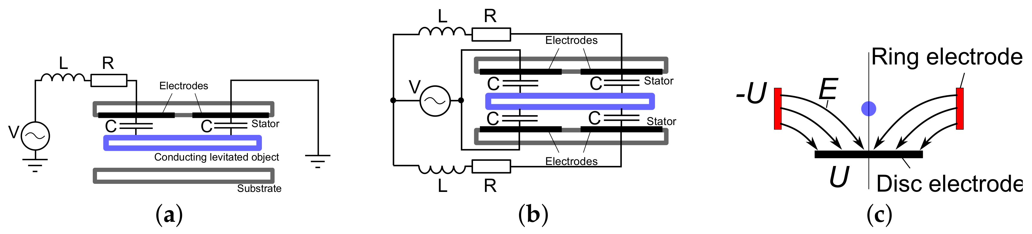
In 1990, the electric levitation micro-actuator (ELMA) based on passive levitation was proposed by Kumar et al. as a solution of the friction problem in MEMS actuators [19]. Using a tuned inductance, capacitance, resistance (LCR) circuit, necessary conditions for open-loop stable levitation of a micro-disc and its dynamics were analyzed. The authors analyzed two designs having a single and dual stator (see Figure 2a,b) and considered their potential application in micro-motors and bearings. Then, in 1992, the single-stator design for an application as micro-bearing was successfully experimentally studied by levitating a micro-plate having a thickness of 180 [21]. The actuator was able to generate a force up to 0.2 along the vertical axis. Then, using a similar single-stator design of ELMA as shown in Figure 2a, but with an active approach for levitation, Higuchi’s group from the University of Tokyo electrically suspended an aluminium disk [22] and a glass plate [23]. Later, adding a variable-capacitance actuation principle to the actuator based on this single stator design, the same group suspended and linearly transported a silicon wafer [24], and demonstrated a motor in which a rotor was revolved with a speed of 60 by applying a rotational torque of 8.6 [25].
In 1994, SatCon Technology Co. developed and successfully demonstrated a prototype of a rotating micro-gyroscope as proof of concept [26]. In this prototype, a rotor disc having a diameter of 200 was driven by multi-phase radial torque actuation. Employing an active approach for stable levitation, the gap between the levitated disc and surrounding electrodes was 2 . The small distance made it possible to generate a drive torque of 10 by applying a nominal drive actuator potential of 5 . This concept of actuation and its application in micro-motors [27,28,29], gyroscopes [30,31,32,33], multi-inertial sensors [34,35] and accelerometers [36,37,38,39], was further improved by other research groups in terms of micro-machining fabrication and signal conditioning. As a result, in 2005, an electrostatic micro-motor which was able to rotate a 1.5 diameter ring-shaped rotor having a speed up to 74,000 , was demonstrated by Nakamura [35]. Using Ball Semiconductor technology, Toda et al. electrostatically levitated a Si-sphere with a diameter of 1 and applied it as a 3-axis accelerometer [36].
By using an oscillatory electric hyperbolic field (the scheme is shown in Figure 2c), Post et al. passively trapped a charged gold particle of 7.5 diameter [40]. Discussing the potential performance of the prototype for application as an inertial sensor, it was shown how trapping parameters could be adjusted to increase dynamic range, and it was demonstrated that a sensitivity comparable to that of a commercial MEMS device was achievable.
An electric micro-actuator based on active levitation found application in high-temperature containerless materials processing. Rhim et al. used the concept to suspend a zirconium sphere of 2.5 diameter in vacuum, and demonstrated multiple superheating-undercooling-recoalescence cycles in the sample (heating the sample up to 2270 K) [41].
4. Magnetic Levitation Micro-Actuators
A magnetic levitated micro-actuator (MLMA), proposed for micro-assembly, was presented by Ye et al. in [42]. The fabricated prototype was composed of three layers of silicon and a permanent magnet, and fabricated using micromachining technology. The top layer consisted of a groove and many pairs of small square coils which were used to generate driving forces. The middle layer consisted of a groove which comprised the moving guide of a permanent magnet. A long rectangular coil built on the bottom layer, as shown schematically in Figure 3a, was used to generate the levitating force. The permanent magnet of 1 volume was lifted up to 200 by generating a levitation force of 20 . Dieppedale et al. developed and demonstrated a prototype of MLMA, in which a levitating mobile magnet of 5 × 40 × 100 volume was used [43]. The prototype employed a bistable actuation principle and was used as a micro-switch. A linear actuator based on active levitation was fabricated and experimentally studied by Ruffert et al. [44,45]. Using a set of parallel coils as schematically shown in Figure 3b, with a length of the magnetic guide coils of 11.4 , a permanent magnet having a length of 4 was levitated at a height of 100 by generating a repulsive force of 1.5 .
In 2005, Dauwalter and Ha described the novel concept of a magnetically suspended spinning rotor [46]. The concept was based on a novel, patented, planar magnetic actuator and position sensor configuration, with a rotor that is rotated by a multi-phase electromagnetic spin motor. The authors proposed its potential application as multi-inertial sensors and micro-motors.
5. Inductive Levitation Micro-Actuators
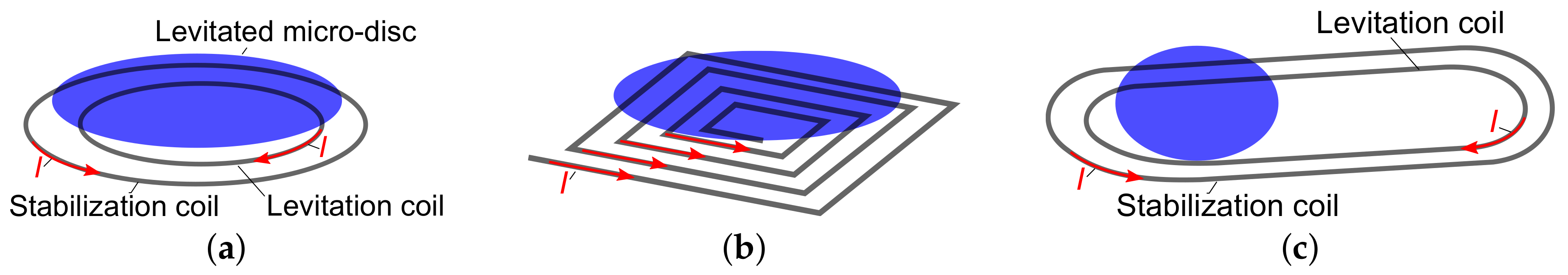
The first micro-machining prototype of inductive levitation micro-actuator (ILMA) was pioneered and fabricated by Shearwood et al. [47] in 1995. A two-coil design, comprising a nested stabilization and levitation coil as shown in Figure 4a, was fabricated by using surface micromachining technology on a soft magnetic backing plane and was able to stably levitate an aluminium disc having a diameter of 400 and thickness of 12 . Shearwood et al. demonstrated the actuation by moving the disc along the vertical direction within a range of 30 and proposed a potential application of the prototype in micro-inertial sensors, micro-motors and actuators [48]. Then in 1996, modifying the two coil design into a three coil stator, the Shearwood group rotated the disc with a speed of 100 [49]. In the framework of the same work, evaporating a gold layer on the one side of the aluminium disc and then using such a multi-layer proof mass as a micro-mirror, the Shearwood group showed the application of ILMA in adaptive optics. Later in 2000, Shearwood et al. improved the original design of the ILMA by embedding a four phase stator. As a result, in addition to vertical actuation, rotation of a micro-disc with a speed of 1000 was demonstrated [50]. In 2006, Zhang et al. separately fabricated coils for levitation and rotation in one ILMA prototype, and was able to rotate a disc of diameter of 2.2 with a speed of 3035 at a height of 200 [51]. The main disadvantage of the above ILMA prototypes was a very high operating temperature, rising up to 600 [50] due to the planar design of the micro-coils. Proposing a spiral coil design as shown in Figure 4b, Tsai et al. fabricated a prototype that was able to stably levitate a conducting cap-shaped proof mass with an operating temperature of 100 [52].
In 2010, the Wallrabe and Korvink groups from the University of Freiburg jointly developed 3D micro-coil technology [9,10], which was later utilized to fabricate an ILMA prototype based on a design of two solenoidal micro-coils (see Figure 4a) with a drastic reduction in heat dissipation [53]. In the framework of this prototype, Wallrabe’s group demonstrated stable levitation of a disc having a diameter of 3.2 and a thickness of 25 , as well as a large increase in actuation range along the vertical axis up to 125 by means of changing the AC current in the coils within the range 80 to 100 . This design was further intensively studied and characterized in terms of stability, dynamics, and electrical performance [17,54,55,56,57]. In particular, recently Badilita’s group at the Karlsruhe Institute of Technology presented a new ILMA design based on 3D micro-coil technology, where the coil structure consists of two racetrack-shaped solenoidal 3D wire-bonded micro-coils, to be used as Maglev rails as shown in Figure 4c [17]. The design allowed an additional translational degree of freedom to the levitated micro-object, and was proposed to be applied as a micro-transporter. A prototype was fabricated and experimentally studied. It was shown that micro-objects with different shapes, such as disc-shaped and plate-shaped platforms could be stably levitated and transported. In 2016, a prototype design with integrated polymer magnetic composite core demonstrated the lowest operating temperature of around 60 among all previously reported ILMAs [58], and indicated the potential for further decrease toward ambient temperatures [59,60].
6. Diamagnetic Levitation Micro-Actuators
In 2004, Lyuksyutov et al. reported the application of diamagnetic-levitated micro-actuators (DLMAs) for on-chip storage and high precision manipulation of levitated droplets of pico to femtolitre volume [61]. The developed magnetic micromanipulation chip consisting of a core with two neodymium-iron-boron permanent magnets (as shown in Figure 5a) having a size of 10 × 10 × h, where the height h was in the range of 100 to 2000, was mounted on a steel substrate containing a set of electrodes. Droplets were moved by current pulses. For measurements, a typical potential well of around 100 in width and glycerin/water (15% glycerin by volume) mixture droplets of 6 ± 0.3 , 9 ± 0.3 and 14 ± 0.3 in diameter, were used. Lyuksyutov et al. showed that the stiffness of the restoring force for a droplet of a 6 ± 0.3 was around 3.0 ± 0.6 . Using electroplated CoPt micro-magnet arrays, Chetouani et al. achieved the levitation and trapping of 3 -large diamagnetic latex beads and microdroplets of water, ethanol and oil [62]. In 2006, Haguet et al. presented a new technology to handle low-volume droplets without any physical contact. This innovative approach of digital microfluidics is based on the diamagnetic trapping of liquids above permanent NdFeB macro- and micro-magnets [63,64]. Later, Pigot et al. fabricated an array of micro-magnets of length 1350 , having a vertical polarization of 1.2 T, and demonstrated the stable levitation of bismuth particles of 5 radius in air, and copper and silicon particles in paramagnetic water [65]. In [66], Kauffmann et al. proposed an integrated electromagnetic hybrid device combining dielectrophoretic (DEP) forces to control the position of levitating droplets along a magnetic groove. The use of these electrodes as micro-conductors to produce variable magnetic fields for magnetophoretic droplet actuation was considered and compared to dielectrophoretic actuation.
Garmire et al. considered the application of DLMA as inertial sensors and demonstrated a proof-of-concept of a diamagnetically levitated micro-accelerometer, in which a plate consisting of a pyrolytic graphite and silicon layer of 6 and 20 thickness, was levitated by a set of four micro-magnets with the design shown in Figure 5b [67]. Using a similar magnet design, Ando et al. demonstrated an inductive readout to measure the linear displacement of a levitated square graphite plate [68]. In 2015, Su et al. levitated a 600--thick micro-disc, which was micro-patterned from highly oriented pyrolytic graphite as a strong diamagnetic material, to a height of 132 by using a ring and disc-shaped magnet design as shown in Figure 5c. The magnet had an outer diameter of 3.175 and inner diameter of 1.588 [69,70]. The application of DLMA in nanoforce sensors was studied theoretically and experimentally by Abadie et al. in [71], where the authors demonstrated a prototype of their sensor with a bandwidth of 4 and a resolution of 5 .
7. Superconducting Levitation Micro-Actuators
In 1989, Kim et al. utilized magnetic levitation using the Meissner effect and presented a new type of superconducting micro-actuator of the order of 100 in size [72,73]. The slider and the stator of the actuator consisted of linear arrays of vertically magnetized permanent magnet and superconductor strips. The authors showed that when the slider is levitated at 50 upon maintaining the operating temperature at 90 , maximum values of driving and levitating forces were 0.26 and 1.7 . The movement of the slider in a particular direction (right or left) was obtained by choosing the driving mode. Coombs et al. presented a micro-motor, where the rotor was levitated by superconducting bearings [74]. The bearings were self-positioning, relying on the Meissner effect to provide a levitation force which moved the rotor into position, and flux pinning to provide stability thereafter.
8. Optical Levitation Micro-Actuators
Micro-actuators have benefited from light, either directly from an actuation force to create movement and force [75], or indirectly to induce chemical, mechanical, electrical, thermal and other effects to be exploited as the actuation force [76]. Optical levitation (or as the optics experts say, optical trapping/tweezing (OT) [11,12,13,14,77]) in microactuators is used as one form of direct actuation force to levitate and manipulate components of a device or objects of interest.
The idea of optical trapping was initiated by Ashkin et al. in the 1970s, where it was shown that milliwatts of laser power can control and trap micron-sized latex particles in a liquid environment in 2D [78]. This first optical trap was created by two counter propagating beams. Later, Ashkin showed that a highly focused single laser beam can trap a transparent particle in 3D and hence the name optical tweezers was given to this phenomenon [79].
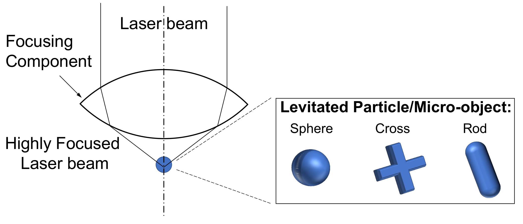
The optical trap is created when an equilibrium state is reached between two optical forces, known as the scattering and gradient force. They are imposed on a particle located in the electromagnetic field of a highly focused light beam. The scattering force acts on a particle in the direction of the light propagation, and gradient force pulls the particle back towards the region of high electric field intensity of the beam. This equilibrium is reached by using a high numerical aperture (NA) focusing component to create the appropriate ratio of the two forces with respect to each other (Figure 6). NA is defined as , in which n specifies the refractive index of the surrounding medium, and is the focusing angle. Furthermore, 3D optical traps occur when using NAs of above 0.75, however, the most efficient optical traps are created by using NAs of above one. The high NA is commonly provided by an immersion microscope objective for trapping objects in a liquid environment. Other approaches such as the use of single or multiple optical fibres [80,81,82,83,84], photonic crystals [85,86], and diffractive optics [87,88,89,90] are intensively pursued as well. Optical waveguides [91] are also used to create an optical trap, either by means of so-called Laguerre-Gaussian mode beam profiles [11,92,93], or other beam intensity profiles, by applying beam shaping elements [94,95]. The focus of this research has always been on increasing the efficiency of the trap by increasing the optical force applied to a levitated object. The applied optical forces are usually in the range of 10 s of . Stable optical trapping of microscopic particles of 25 to 10 diameter is successfully practiced by several research and commercial [96,97,98] groups.
Optical tweezers not only enable the contactless levitation of particles, but also create a torque to rotate the particle. The value of the optical torque is usually around 100 s of . This is possible by various approaches such as transferring orbital angular momentum [99,100,101], manipulation of the light polarization state/direction [102,103,104], application of circular or elliptical polarization [105,106,107], or varying the intensity distribution of the beam [108,109,110]. Higurashi et al. [111] used the latter approach to show rotation of micro-objects of specific shape with cross-sectional diameter of 12–15 , in a high and low refractive index medium with rotational speed of 6 In another work they showed that micro-objects with rotational symmetry can also rotate in an optical trap [112]. Such successful examples of optical levitation and optically driven rotation has paved the way to use light in the field of microactuators.
In addition, the development of two photon lithography [15] eased the fabrication of arbitrary-shaped 3D microrotors out of transparent photopolymers, and resulted in successful demonstration of optically driven micropumps and microvalves in microfluidic devices. The first micromachine was shown by Galadja and Ormos in 2001 [113], in which rotors of helix, sprinkler and propeller shape fabricated by two photon lithography and of less than 5 diameter were optically levitated and rotated. Similar developments made it possible to make and control microdevices with great precision. Examples of such microdevices included microstirrers [106,114], microvalves [115,116], micropumps [117,118,119] and manipulators [120,121].
9. Hybrid Levitation Micro-Actuators
An attractive application of LMAs is that they provide one of the best mechanisms with which to handle very small and fragile objects, for example when the force required for handling is limited by thermally fluctuating forces due to Nyquist and Johnson noise. Two ways for guiding the level of fluctuating forces, which also define the limit of performance of LMAs, have been hlrecognized and implemented. The first technique decreases the friction in the LMA by controlling vacuum, since the fluctuating force due to Nyquist noise, , is thereby directly controlled. However, the Johnson noise force, , limits the possibility to control fluctuations only by means of vacuum. It requires controlling the dynamics of the actuator as well, which can be achieved by a combination of different force fields and brings us to extend our list of classifications of LMAs by the term hybrid levitated micro-actuators (HLMA).
An HLMA based on a combination of electric and inductive force fields, in which the vertical component of stiffness of an inductive suspension can be controlled and varied in a wide range, was proposed by Poletkin et al. [122]. The concept was realized in a micro-prototype reported in [123,124], where electrostatic forces acting at the bottom and top surfaces of the inductively levitated disc maintained its equilibrium position, and, at the same time, decreased the vertical component of stiffness of the inductive suspension by means of increasing the strength of the electrostatic field. In 2015, Poletkin et al. presented an HLMA based on the same combination of force fields, where linear and angular positioning, bistable linear and angular actuations, and the adjustment of stiffness components of a levitated disc having a diameter of 2.8 and a thickness of 13 , were implemented [125].
Moreover, HLMAs based on a combination of electric and inductive force fields found application in gyroscopes, accelerators and transporters. Thus, Tsai et al. inductively levitated a conducting cap-shaped rotor, and electrostatically revolved it with a speed of 2000 [52]. Subsequently, Kraft’s group proposed a design of the accelerator and experimentally demonstrated that a 1 × 1 sized and 7 thick micro object could be levitated to a maximum height of 82 and propelled forward continuously at a maximum average forward velocity of 3.6 [126]. In 2016, Poletkin et al. demonstrated a prototype of a micro-transporter employing 3D micro-coil technology and electrostatic actuation to propel a levitated micro-object [57].
Combining diamagnetic and electric force fields, Kauffmann et al. successfully levitated several repulsively charged picolitre droplets, performed in a ∼1 adjustable flat magnetic well, which was provided by a centimeter-sized cylindrical permanent magnet structure [128]. The application of the HLMA using the same combination in micro-motors was exhibited by Liu et al. [129] and Xu et al. [130].
In 2009, Liu et al. presented an HLMA, where diamagnetic and inductive force fields were combined [131]. Such a hybrid actuator provides an improvement in the energy performance of an LMA in comparison with that based on diamagnetic or inductive effects only.
10. Summary and Future Trends
In this review, levitating micro-actuators have been surveyed. It was observed that, in order to employ the phenomenon of electro-magnetic levitation in micro-actuators, a wide spectrum of physical principles have been utilized and successfully implemented by using different techniques for micro-fabrication. This fact already gave rise to a new generation of micro-actuators, which have found application in a widespread domain as summarized and shown in Table 1. However, the potential, and the resulting capabilities of levitating microactuators have not yet been exhaustively demonstrated, mainly due to a number of remaining technological challenges.
Electric levitation micro-actuators have been well established from the micro-fabrication point of view. However, an accurate control of the gap between a levitated mass and surrounding electrodes is required to be efficient. Solving this issue by employing the active control for stable levitation increases complexity for designing ELMA, which in turn restricts the possibility of improving their performance for the current application and shrinks their domain of further application.
Using a permanent magnet in magnetic, diamagnetic and superconducting levitation micro-actuators has a manifest benefit, such as passive levitation without the requirement of direct energy consumption. However, magnetic levitation employing static magnetic fields either requires new diamagnetic materials with a high magnetic susceptibility (>1 × 10), or novel high temperature superconducting materials. The development of effective fabrication techniques for the integration of permanent micro-magnets is also required.
Recent improvement in the performance of inductive levitation micro-actuators by means of using 3D micro-coil technology together with the integration of a polymer magnetic composite material for flux concentration has established ILMA as a promising integrated element of micro-systems. Nevertheless, further development of the magnetic properties of electroplated soft magnetic layers is required.
In the field of optical levitation micro-actuators, the microscope objective is the most widely used setup to provide a levitating force. However, this setup is bulky and still suffers from the diffraction limit, which limits the size of objects to be levitated. Clearly, novel optical systems must be developed.
Another point is that levitation itself will benefit from improvements in the performance and capabilities of LMA through a combination of different force fields (hybrid levitation). A key potential feature of HLMA is to use passive levitation. In particular, inductive levitation produces a passive levitation effect, which can be combined with all other force fields without interrupting the stability. This fact leads to new combinations. For instance, inductive levitation of a permanent micro-magnet interacting with a DC electric current will improve the energy performance of the LMA. A combination of an inductively levitated micro-object with an optical force field for revolution and transportation will improve the functionality of the LMA. Other combinations of force fields are of course also possible.
Acknowledgments
K.P. acknowledges with thanks support from the German Research Foundation (Grant KO 1883/26-1).
Conflicts of Interest
The authors declare no conflict of interest.
Abbreviations
The following abbreviations are used in this manuscript:
| AC | Alternate current |
| c | Stiffness, N/m |
| DC | Direct current |
| DLMA | Diamagnetic levitation micro-actuators |
| ELMA | Electric levitation micro-actuators |
| HLMA | Hybrid levitation micro-actuators |
| ILMA | Inductive levitation micro-actuators |
| Boltzmann constant, JK | |
| LMA | Levitating micro-actuators |
| MLMA | Magnetic levitation micro-actuators |
| MEMS | Micro-Electro-Mechanical Systems |
| NA | numerical aperture |
| OLMA | Optical levitation micro-actuators |
| OT | Optical Trapping |
| revolution per minute | |
| SLMA | Superconducting levitation micro-actuators |
| T | Absolute temperature, K |
| Frequency band, Hz |
References
- Petersen, K.E. Silicon as a mechanical material. Proc. IEEE 1982, 70, 420–457. [Google Scholar] [CrossRef]
- Boxenhorn, B.; Greiff, P. Monolithic silicon accelerometer. Sens. Actuators A Phys. 1990, 21, 273–277. [Google Scholar] [CrossRef]
- Polla, D.L.; Erdman, A.G.; Robbins, W.P.; Markus, D.T.; Diaz-Diaz, J.; Rizq, R.; Nam, Y.; Brickner, H.T.; Wang, A.; Krulevitch, P. Microdevices in medicine. Annu. Rev. Biomed. Eng. 2000, 2, 551–576. [Google Scholar] [CrossRef] [PubMed]
- Feynman, R.P. There’s plenty of room at the bottom. Eng. Sci. 1960, 23, 22–36. [Google Scholar]
- Thielicke, E.; Obermeier, E. Microactuators and their technologies. Mechatronics 2000, 10, 431–455. [Google Scholar] [CrossRef]
- Fujita, H. Microactuators and micromachines. Proc. IEEE 1998, 86, 1721–1732. [Google Scholar] [CrossRef]
- Poletkin, K.V.; Korvink, J.G.; Badilita, V. Mechanical Thermal Noise in Micro-Machined Levitated Two-Axis Rate Gyroscopes. IEEE Sens. J. 2018, 18, 1390–1402. [Google Scholar] [CrossRef]
- Arnold, D.P.; Wang, N. Permanent magnets for MEMS. J. Microelectromech. Syst. 2009, 18, 1255–1266. [Google Scholar] [CrossRef]
- Kratt, K.; Badilita, V.; Burger, T.; Korvink, J.; Wallrabe, U. A fully MEMS-compatible process for 3D high aspect ratio micro coils obtained with an automatic wire bonder. J. Micromech. Microeng. 2010, 20, 015021. [Google Scholar] [CrossRef]
- Fischer, A.C.; Korvink, J.G.; Roxhed, N.; Stemme, G.; Wallrabe, U.; Niklaus, F. Unconventional applications of wire bonding create opportunities for microsystem integration. J. Micromech. Microeng. 2013, 23, 083001. [Google Scholar] [CrossRef]
- Neuman, K.C.; Block, S.M. Optical trapping. Rev. Sci. Instrum. 2004, 75, 2787–2809. [Google Scholar] [CrossRef] [PubMed]
- Lang, M.J.; Block, S.M. Resource Letter: LBOT-1: Laser-based optical tweezers. Am. J. Phys. 2003, 71, 201–215. [Google Scholar] [CrossRef] [PubMed]
- Moffitt, J.R.; Chemla, Y.R.; Smith, S.B.; Bustamante, C. Recent advances in optical tweezers. Annu. Rev. Biochem. 2008, 77. [Google Scholar] [CrossRef] [PubMed]
- Verdeny, I.; Farré, A.; Mas Soler, J.; López Quesada, C.; Martín Badosa, E.; Montes Usategui, M. Optical trapping: A review of essential concepts. In Óptica Pura y Aplicada; SEDO—Sociedad Española de Óptica: Madrid, Spain, 2011; Volume 44, pp. 527–551. [Google Scholar]
- Baldacchini, T. Three-Dimensional Microfabrication Using Two-Photon Polymerization: Fundamentals, Technology, and Applications; William Andrew: Norwich, NY, USA, 2015. [Google Scholar]
- Mariappan, S.G.; Moazenzadeh, A.; Wallrabe, U. Polymer magnetic composite core based microcoils and microtransformers for very high frequency power applications. Micromachines 2016, 7, 60. [Google Scholar] [CrossRef]
- Poletkin, K.; Lu, Z.; Wallrabe, U.; Korvink, J.; Badilita, V. Stable dynamics of micro-machined inductive contactless suspensions. Int. J. Mech. Sci. 2017, 131-132, 753–766. [Google Scholar] [CrossRef]
- Earnshaw, S. On the nature of the molecular forces which regulate the constitution of the luminiferous ether. Trans. Camb. Phil. Soc. 1842, 7, 97–112. [Google Scholar]
- Kumar, S.; Cho, D.; Carr, W. A proposal for electrically levitating micromotors. Sens. Actuators. A Phys. 1990, 24, 141–149. [Google Scholar] [CrossRef]
- Paul, W. Electromagnetic traps for charged and neutral particles. Rev. Mod. Phys. 1990, 62, 531–540. [Google Scholar] [CrossRef]
- Kumar, S.; Cho, D.; Carr, W.N. Experimental study of electric suspension for microbearings. J. Microelectromech. Syst. 1992, 1, 23–30. [Google Scholar] [CrossRef]
- Jin, L.; Higuchi, T.; Kanemoto, M. Electrostatic levitator for hard disk media. IEEE Trans. Ind. Electron. 1995, 42, 467–473. [Google Scholar] [CrossRef]
- Jeon, J.U.; Higuchi, T. Electrostatic suspension of dielectrics. IEEE Trans. Ind. Electron. 1998, 45, 938–946. [Google Scholar] [CrossRef]
- Jin, J.; Yih, T.C.; Higuchi, T.; Jeon, J.U. Direct electrostatic levitation and propulsion of silicon wafer. IEEE Trans. Ind. Appl. 1998, 34, 975–984. [Google Scholar] [CrossRef]
- Jeon, J.U.; Woo, S.J.; Higuchi, T. Variable-capacitance motors with electrostatic suspension. Sens. Actuators A Phys. 1999, 75, 289–297. [Google Scholar] [CrossRef]
- Torti, R.P.; Gondhalekar, V.; Tran, H.; Selfors, B.; Bart, S.; Maxwell, B. Electrostatically suspended and sensed micromechanical rate gyroscope. In Proceedings of the SPIE’s International Symposium on Optical Engineering and Photonics in Aerospace Sensing, Orlando, FL, USA, 13 June 1994; Volume 2220. [Google Scholar]
- Han, F.; Fu, Z.; Dong, J. Design and simulation of an active electrostatic bearing for MEMS micromotors. In Proceedings of the 2009 4th IEEE International Conference on Nano/Micro Engineered and Molecular Systems, Shenzhen, China, 5–8 January 2009; pp. 80–85. [Google Scholar]
- Han, F.T.; Wu, Q.P.; Wang, L. Experimental study of a variable-capacitance micromotor with electrostatic suspension. J. Micromech. Microeng. 2010, 20, 115034. [Google Scholar] [CrossRef]
- Han, F.T.; Wang, L.; Wu, Q.P.; Liu, Y.F. Performance of an active electric bearing for rotary micromotors. J. Micromech. Microeng. 2011, 21, 085027. [Google Scholar] [CrossRef]
- Damrongsak, B.; Kraft, M. A micromachined electrostatically suspended gyroscope with digital force feedback. In Proceedings of the 2005 IEEE Sensors, Irvine, CA, USA, 30 October–3 November 2005. [Google Scholar]
- Damrongsak, B.; Kraft, M.; Rajgopal, S.; Mehregany, M. Design and fabrication of a micromachined electrostatically suspended gyroscope. Proc. Inst. Mech. Eng. Part C J. Mech. Eng. Sci. 2008, 222, 53–63. [Google Scholar] [CrossRef]
- Han, F.T.; Liu, Y.F.; Wang, L.; Ma, G.Y. Micromachined electrostatically suspended gyroscope with a spinning ring-shaped rotor. J. Micromech. Microeng. 2012, 22, 105032. [Google Scholar] [CrossRef]
- Sun, B.; Han, F.; Li, L.; Wu, Q. Rotation Control and Characterization of High-Speed Variable-Capacitance Micromotor Supported on Electrostatic Bearing. IEEE Trans. Ind. Electron. 2016, 63, 4336–4345. [Google Scholar] [CrossRef]
- Murakoshi, T.; Endo, Y.; Fukatsu, K.; Nakamura, S.; Esashi, M. Electrostatically levitated ring-shaped rotational gyro/accelerometer. Jpn. J. Appl. Phys 2003, 42, 2468–2472. [Google Scholar] [CrossRef]
- Nakamura, S. MEMS inertial sensor toward higher accuracy & multi-axis sensing. In Proceedings of the 4th IEEE Conference on 2005 IEEE Sensors, Irvine, CA, USA, 30 October–3 November 2005; pp. 939–942. [Google Scholar]
- Toda, R.; Takeda, N.; Murakoshi, T.; Nakamura, S.; Esashi, M. Electrostatically levitated spherical 3-axis accelerometer. In Proceedings of the Fifteenth IEEE International Conference on Micro Electro Mechanical Systems, (Cat. No. 02CH37266), Las Vegas, NV, USA, 24 January 2002; pp. 710–713. [Google Scholar]
- Han, F.; Gao, Z.; Li, D.; Wang, Y. Nonlinear compensation of active electrostatic bearings supporting a spherical rotor. Sens. Actuators A Phys. 2005, 119, 177–186. [Google Scholar] [CrossRef]
- Cui, F.; Liu, W.; Chen, W.; Zhang, W.; Wu, X. Design, Fabrication and Levitation Experiments of a Micromachined Electrostatically Suspended Six-Axis Accelerometer. Sensors 2011, 11, 11206–11234. [Google Scholar] [CrossRef] [PubMed]
- Han, F.; Sun, B.; Li, L.; Wu, Q. Performance of a Sensitive Micromachined Accelerometer With an Electrostatically Suspended Proof Mass. IEEE Sens. J. 2015, 15, 209–217. [Google Scholar]
- Post, E.R.; Popescu, G.A.; Gershenfeld, N. Inertial measurement with trapped particles: A microdynamical system. Appl. Phys. Lett. 2010, 96, 143501. [Google Scholar] [CrossRef]
- Rhim, W.; Chung, S.K.; Barber, D.; Man, K.F.; Gutt, G.; Rulison, A.; Spjut, R.E. An electrostatic levitator for high-temperature containerless materials processing in 1-g. Rev. Sci. Instrum. 1993, 64, 2961–2970. [Google Scholar] [CrossRef]
- Ye, X.Y.; Huang, Y.; Zhou, Z.Y.; Li, Q.C.; Gong, Q.L. A magnetic levitation actuator for micro-assembly. In Proceedings of the TRANSDUCERS ’97 Chicago International Conference on Solid State Sensors and Actuators, Chicago, IL, USA, 19 June 1997; Volume 2, pp. 797–799. [Google Scholar]
- Dieppedale, C.; Desloges, B.; Rostaing, H.; Delamare, J.; Cugat, O.; Meunier-Carus, J. Magnetic bistable micro-actuator with integrated permanent magnets. In Proceedings of the IEEE Sensors, Vienna, Austria, 24–27 October 2004; Volume 1, pp. 493–496. [Google Scholar]
- Ruffert, C.; Gehrking, R.; Ponick, B.; Gatzen, H.H. Magnetic Levitation Assisted Guide for a Linear Micro-Actuator. IEEE Trans. Magn. 2006, 42, 3785–3787. [Google Scholar] [CrossRef]
- Ruffert, C.; Li, J.; Denkena, B.; Gatzen, H.H. Development and Evaluation of an Active Magnetic Guide for Microsystems With an Integrated Air Gap Measurement System. IEEE Trans. Magn. 2007, 43, 2716–2718. [Google Scholar] [CrossRef]
- Dauwalter, C.R.; Ha, J.C. Magnetically suspended MEMS spinning wheel gyro. IEEE Aerosp. Electron. Syst. Mag. 2005, 20, 21–26. [Google Scholar] [CrossRef]
- Shearwood, C.; Williams, C.; Mellor, P.; Yates, R.; Gibbs, M.; Mattingley, A. Levitation of a micromachined rotor for application in a rotating gyroscope. Electron. Lett. 1995, 31, 1845–1846. [Google Scholar] [CrossRef]
- Williams, C.; Shearwood, C.; Mellor, P.; Mattingley, A.; Gibbs, M.; Yates, R. Initial fabrication of a micro-induction gyroscope. Microelectron. Eng. 1996, 30, 531–534. [Google Scholar] [CrossRef]
- Shearwood, C.; Williams, C.B.; Mellor, P.H.; Chang, K.Y.; Woodhead, J. Electro-magnetically levitated micro-discs. In Proceedings of the IEE Colloquium on Microengineering Applications in Optoelectronics, London, UK, 27 February 1996. [Google Scholar]
- Shearwood, C.; Ho, K.; Williams, C.; Gong, H. Development of a levitated micromotor for application as a gyroscope. Sens. Actuators A Phys. 2000, 83, 85–92. [Google Scholar] [CrossRef]
- Zhang, W.; Chen, W.; Zhao, X.; Wu, X.; Liu, W.; Huang, X.; Shao, S. The study of an electromagnetic levitating micromotor for application in a rotating gyroscope. Sens. Actuators A Phys. 2006, 132, 651–657. [Google Scholar] [CrossRef]
- Tsai, N.C.; Huan, W.M.; Chiang, C.W. Magnetic actuator design for single-axis micro-gyroscopes. Microsyst. Technol. 2009, 15, 493–503. [Google Scholar] [CrossRef]
- Badilita, V.; Rzesnik, S.; Kratt, K.; Wallrabe, U. Characterization of the 2nd generation magnetic microbearing with integrated stabilization for frictionless devices. In Proceedings of the 2011 16th International Solid-State Sensors, Actuators and Microsystems Conference, Beijing, China, 5–9 June 2011; pp. 1456–1459. [Google Scholar]
- Lu, Z.; Jia, F.; Korvink, J.; Wallrabe, U.; Badilita, V. Design optimization of an electromagnetic microlevitation System based on copper wirebonded coils. In Proceedings of the 2012 Power MEMS, Atlanta, GA, USA, 2–5 December 2012; pp. 363–366. [Google Scholar]
- Lu, Z.; Poletkin, K.; den Hartogh, B.; Wallrabe, U.; Badilita, V. 3D micro-machined inductive contactless suspension: Testing and modeling. Sens. Actuators A Phys. 2014, 220, 134–143. [Google Scholar] [CrossRef]
- Lu, Z.; Poletkin, K.; Wallrabe, U.; Badilita, V. Performance Characterization of Micromachined Inductive Suspensions Based on 3D Wire-Bonded Microcoils. Micromachines 2014, 5, 1469–1484. [Google Scholar] [CrossRef]
- Poletkin, K.V.; Lu, Z.; Wallrabe, U.; Korvink, J.G.; Badilita, V. A qualitative technique to study stability and dynamics of micro-machined inductive contactless suspensions. In Proceedings of the 2017 19th International Conference on Solid-State Sensors, Actuators and Microsystems (TRANSDUCERS), Kaohsiung, Taiwan, 18–22 June 2017; pp. 528–531. [Google Scholar]
- Poletkin, K.V.; Lu, Z.; Moazenzadeh, A.; Mariappan, S.G.; Korvink, J.G.; Wallrabe, U.; Badilita, V. Polymer Magnetic Composite Core Boosts Performance of Three-Dimensional Micromachined Inductive Contactless Suspension. IEEE Magn. Lett. 2016, 7, 1–3. [Google Scholar] [CrossRef]
- Poletkin, K.V.; Lu, Z.; Maozenzadeh, A.; Mariappan, S.G.; Korvink, J.; Wallrabe, U.; Badilita, V. 3D Micro-machined Inductive Suspensions with the Lowest Energy Consumption. In MikroSystemTechnik Kongress 2017; VDE Verlag: München, Germany, 2017; pp. 500–502. [Google Scholar]
- Poletkin, K.V.; Lu, Z.; Moazenzadeh, A.; Mariappan, S.G.; Korvink, J.G.; Wallrabe, U.; Badilita, V. Energy aware 3D micro-machined inductive suspensions with polymer magnetic composite core. In Proceedings of the 17th International Conference on Micro and Nanotechnology for Power Generation and Energy Conversion Applications Power MEMS 2017, Kanazawa, Japan, 14–17 November 2017; pp. 219–222. [Google Scholar]
- Lyuksyutov, I.F.; Naugle, D.G.; Rathnayaka, K.D.D. On-chip manipulation of levitated femtodroplets. Appl. Phys. Lett. 2004, 85, 1817–1819. [Google Scholar] [CrossRef]
- Chetouani, H.; Jeandey, C.; Haguet, V.; Rostaing, H.; Dieppedale, C.; Reyne, G. Diamagnetic Levitation With Permanent Magnets for Contactless Guiding and Trapping of Microdroplets and Particles in Air and Liquids. IEEE Trans. Magn. 2006, 42, 3557–3559. [Google Scholar] [CrossRef]
- Haguet, V.; Jeandey, C.; Chetouani, H.; Reyne, G.; Chatelain, F. Magnetic levitation of microdroplets in air. In Proceedings of the 10th International Conference on Miniaturized Systems for Chemistry and Life Sciences (MicroTAS), Tokyo, Japan, 5–9 November 2006; Volume 1, pp. 110–112. [Google Scholar]
- Jeandey, C.; Chetouani, H.; Haguet, V.; Chatelain, F.; Reyne, G. Diamagnetic levitation based digital microfluidics. In Proceedings of the MicroTAS, Paris, France, 7–11 October 2007; Volume 2, pp. 922–924. [Google Scholar]
- Pigot, C.; Chetouani, H.; Poulin, G.; Reyne, G. Diamagnetic Levitation of Solids at Microscale. IEEE Trans. Magn. 2008, 44, 4521–4524. [Google Scholar] [CrossRef]
- Kauffmann, P.; Pham, P.; Masse, A.; Kustov, M.; Honegger, T.; Peyrade, D.; Haguet, V.; Reyne, G. Contactless Dielectrophoretic Handling of Diamagnetic Levitating Water Droplets in Air. IEEE Trans. Magn. 2010, 46, 3293–3296. [Google Scholar] [CrossRef]
- Garmire, D.; Choo, H.; Kant, R.; Govindjee, S.; Sequin, C.H.; Muller, R.S.; Demmel, J. Diamagnetically Levitated MEMS Accelerometers. In Proceedings of the 2007 International Solid-State Sensors, Actuators and Microsystems Conference, Lyon, France, 10–14 June 2007; pp. 1203–1206. [Google Scholar]
- Ando, B.; Baglio, S.; Marletta, V.; Valastro, A. A Short-Range Inertial Sensor Exploiting Magnetic Levitation and an Inductive Readout Strategy. IEEE Trans. Instrum. Meas. 2018, PP, 1–8. [Google Scholar] [CrossRef]
- Su, Y.; Xiao, Z.; Ye, Z.; Takahata, K. Micromachined Graphite Rotor Based on Diamagnetic Levitation. IEEE Electron Device Lett. 2015, 36, 393–395. [Google Scholar] [CrossRef]
- Su, Y.; Zhang, K.; Ye, Z.; Xiao, Z.; Takahata, K. Exploration of micro-diamagnetic levitation rotor. Jpn. J. Appl. Phys. 2017, 56, 126702. [Google Scholar] [CrossRef]
- Abadie, J.; Piat, E.; Oster, S.; Boukallel, M. Modeling and experimentation of a passive low frequency nanoforce sensor based on diamagnetic levitation. Sens. Actuators A Phys. 2012, 173, 227–237. [Google Scholar] [CrossRef] [Green Version]
- Kim, Y.; Katsurai, M.; Fujita, H. A proposal for a superconducting actuator using Meissner effect. In Proceedings of the an Investigation of Micro Structures, Sensors, Actuators, Machines and Robots, Micro Electro Mechanical Systems, Salt Lake City, UT, USA, 20–22 February 1989; pp. 107–112. [Google Scholar]
- Kim, Y.K.; Katsurai, M.; Fujita, H. A superconducting actuator using the Meissner effect. Sens. Actuators 1989, 20, 33–40. [Google Scholar] [CrossRef]
- Coombs, T.A.; Samad, I.; Ruiz-Alonso, D.; Tadinada, K. Superconducting micro-bearings. IEEE Trans. Appl. Supercond. 2005, 15, 2312–2315. [Google Scholar] [CrossRef]
- Lin, C.L.; Li, Y.H.; Lin, C.T.; Chiang, C.C.; Liu, Y.J.; Chung, T.T.; Baldeck, P.L. Preliminary study of lever-based optical driven micro-actuator. In Proceedings of the Third International Conference on Smart Materials and Nanotechnology in Engineering, Shenzhen, China, 11–13 November 2011; Volume 8409, p. 840920. [Google Scholar]
- Tabib-Azar, M. Optically controlled silicon microactuators. Nanotechnology 1990, 1, 81–92. [Google Scholar] [CrossRef]
- Svoboda, K.; Block, S.M. Biological applications of optical forces. Annu. Rev. Biophys. Biomol. Struct. 1994, 23, 247–285. [Google Scholar] [CrossRef] [PubMed]
- Ashkin, A. Acceleration and trapping of particles by radiation pressure. Phys. Rev. Lett. 1970, 24, 156. [Google Scholar] [CrossRef]
- Ashkin, A.; Dziedzic, J.M.; Bjorkholm, J.; Chu, S. Observation of a single-beam gradient force optical trap for dielectric particles. Opt. Lett. 1986, 11, 288–290. [Google Scholar] [CrossRef] [PubMed]
- Abedin, K.S.; Kerbage, C.; Fernandez-Nieves, A.; Weitz, D.A. Optical manipulation and rotation of liquid crystal drops using high-index fiber-optic tweezers. Appl. Phys. Lett. 2007, 91, 091119. [Google Scholar] [CrossRef]
- Decombe, J.B.; Huant, S.; Fick, J. Single and dual fiber nano-tip optical tweezers: Trapping and analysis. Opt. Express 2013, 21, 30521–30531. [Google Scholar] [CrossRef] [PubMed]
- Bragheri, F.; Minzioni, P.; Liberale, C.; Fabrizio, E.D.; Cristiani, I. Design and optimization of a reflection-based fiber-optic tweezers. Opt. Express 2008, 16, 17647–17653. [Google Scholar] [CrossRef] [PubMed]
- Cabrini, S.; Liberale, C.; Cojoc, D.; Carpentiero, A.; Prasciolu, M.; Mora, S.; Degiorgio, V.; Angelis, F.D.; Fabrizio, E.D. Axicon lens on optical fiber forming optical tweezers, made by focused ion beam milling. Microelectron. Eng. 2006, 83, 804–807. [Google Scholar] [CrossRef]
- Liberale, C.; Cojoc, G.; Bragheri, F.; Minzioni, P.; Perozziello, G.; La Rocca, R.; Ferrara, L.; Rajamanickam, V.; Di Fabrizio, E.; Cristiani, I. Integrated microfluidic device for single-cell trapping and spectroscopy. Sci. Rep. 2013, 3, 1258. [Google Scholar] [CrossRef] [PubMed]
- Van Leest, T.; Caro, J. Cavity-enhanced optical trapping of bacteria using a silicon photonic crystal. Lab Chip 2013, 13, 4358–4365. [Google Scholar] [CrossRef] [PubMed]
- Krishnan, A.; Huang, N.; Wu, S.H.; Martínez, L.J.; Povinelli, M.L. Enhanced and selective optical trapping in a slot-graphite photonic crystal. Opt. Express 2016, 24, 23271–23279. [Google Scholar] [CrossRef] [PubMed]
- Grier, D.G. A revolution in optical manipulation. Nature 2003, 424, 810. [Google Scholar] [CrossRef] [PubMed]
- Curtis, J.E.; Koss, B.A.; Grier, D.G. Dynamic holographic optical tweezers. Opt. Commun. 2002, 207, 169–175. [Google Scholar] [CrossRef]
- Fournier, J.M.R.; Burns, M.M.; Golovchenko, J.A. Writing diffractive structures by optical trapping. In Proceedings of the Practical Holography IX. International Society for Optics and Photonics, San Jose, CA, USA, 5–10 February 1995; Volume 2406, pp. 101–112. [Google Scholar]
- He, H.; Friese, M.; Heckenberg, N.; Rubinsztein-Dunlop, H. Direct observation of transfer of angular momentum to absorptive particles from a laser beam with a phase singularity. Phys. Rev. Lett. 1995, 75, 826. [Google Scholar] [CrossRef] [PubMed]
- Bellini, N.; Vishnubhatla, K.C.; Bragheri, F.; Ferrara, L.; Minzioni, P.; Ramponi, R.; Cristiani, I.; Osellame, R. Femtosecond laser fabricated monolithic chip for optical trapping and stretching of single cells. Opt. Express 2010, 18, 4679–4688. [Google Scholar] [CrossRef] [PubMed]
- Ganic, D.; Gan, X.; Gu, M. Optical trapping force with annular and doughnut laser beams based on vectorial diffraction. Opt. Express 2005, 13, 1260–1265. [Google Scholar] [CrossRef] [PubMed]
- Gu, M.; Morrish, D.; Ke, P.C. Enhancement of transverse trapping efficiency for a metallic particle using an obstructed laser beam. Appl. Phys. Lett. 2000, 77, 34–36. [Google Scholar] [CrossRef]
- Aieta, F.; Genevet, P.; Kats, M.A.; Yu, N.; Blanchard, R.; Gaburro, Z.; Capasso, F. Aberration-free ultrathin flat lenses and axicons at telecom wavelengths based on plasmonic metasurfaces. Nano Lett. 2012, 12, 4932–4936. [Google Scholar] [CrossRef] [PubMed]
- Kampmann, R.; Chall, A.; Kleindienst, R.; Sinzinger, S. Optical system for trapping particles in air. Appl. Opt. 2014, 53, 777–784. [Google Scholar] [CrossRef] [PubMed]
- JPK; JPK Instruments AG: Berlin, Germany, 2018.
- MMI; Molecular Machines and Industries GmbH: Eching, Germany, 2018.
- Thorlabs; Thorlabs Inc.: Newton, NJ, USA, 2018.
- Dholakia, K.; MacDonald, M.; Spalding, G. Optical tweezers: The next generation. Phys. World 2002, 15, 31. [Google Scholar] [CrossRef]
- Friese, M.; Enger, J.; Rubinsztein-Dunlop, H.; Heckenberg, N.R. Optical angular-momentum transfer to trapped absorbing particles. Phys. Rev. A 1996, 54, 1593. [Google Scholar] [CrossRef] [PubMed]
- Padgett, M.; Bowman, R. Tweezers with a twist. Nat. Photonics 2011, 5, 343. [Google Scholar] [CrossRef]
- Bayoudh, S.; Nieminen, T.; Heckenberg, N.; Rubinsztein-Dunlop, H. Orientation of biological cells using plane-polarized Gaussian beam optical tweezers. J. Mod. Opt. 2003, 50, 1581–1590. [Google Scholar] [CrossRef]
- Dharmadhikari, J.; Roy, S.; Dharmadhikari, A.; Sharma, S.; Mathur, D. Torque-generating malaria-infected red blood cells in an optical trap. Opt. Express 2004, 12, 1179–1184. [Google Scholar] [CrossRef] [PubMed]
- Gutiérrez-Medina, B.; Andreasson, J.O.; Greenleaf, W.J.; LaPorta, A.; Block, S.M. An optical apparatus for rotation and trapping. In Methods in Enzymology; Elsevier: New York, NY, USA, 2010; Volume 475, pp. 377–404. [Google Scholar]
- Arita, Y.; Mazilu, M.; Dholakia, K. Laser-induced rotation and cooling of a trapped microgyroscope in vacuum. Nat. Commun. 2013, 4, 2374. [Google Scholar] [CrossRef] [PubMed] [Green Version]
- Galajda, P.; Ormos, P. Rotors produced and driven in laser tweezers with reversed direction of rotation. Appl. Phys. Lett. 2002, 80, 4653–4655. [Google Scholar] [CrossRef]
- La Porta, A.; Wang, M.D. Optical torque wrench: Angular trapping, rotation, and torque detection of quartz microparticles. Phys. Rev. Lett. 2004, 92, 190801. [Google Scholar] [CrossRef] [PubMed]
- O’Neil, A.T.; Padgett, M.J. Rotational control within optical tweezers by use of a rotating aperture. Opt. Lett. 2002, 27, 743–745. [Google Scholar] [CrossRef] [PubMed]
- MacDonald, M.; Volke-Sepulveda, K.; Paterson, L.; Arlt, J.; Sibbett, W.; Dholakia, K. Revolving interference patterns for the rotation of optically trapped particles. Opt. Commun. 2002, 201, 21–28. [Google Scholar] [CrossRef]
- Paterson, L.; MacDonald, M.; Arlt, J.; Sibbett, W.; Bryant, P.; Dholakia, K. Controlled rotation of optically trapped microscopic particles. Science 2001, 292, 912–914. [Google Scholar] [CrossRef] [PubMed]
- Higurashi, E.; Ohguchi, O.; Tamamura, T.; Ukita, H.; Sawada, R. Optically induced rotation of dissymmetrically shaped fluorinated polyimide micro-objects in optical traps. J. Appl. Phys. 1997, 82, 2773–2779. [Google Scholar] [CrossRef]
- Higurashi, E.; Ukita, H.; Tanaka, H.; Ohguchi, O. Optically induced rotation of anisotropic micro-objects fabricated by surface micromachining. Appl. Phys. Lett. 1994, 64, 2209–2210. [Google Scholar] [CrossRef]
- Galajda, P.; Ormos, P. Complex micromachines produced and driven by light. Appl. Phys. Lett. 2001, 78, 249–251. [Google Scholar] [CrossRef]
- Neale, S.L.; MacDonald, M.P.; Dholakia, K.; Krauss, T.F. All-optical control of microfluidic components using form birefringence. Nat. Mater. 2005, 4, 530. [Google Scholar] [CrossRef] [PubMed]
- Terray, A.; Oakey, J.; Marr, D.W.M. Fabrication of linear colloidal structures for microfluidic applications. Appl. Phys. Lett. 2002, 81, 1555–1557. [Google Scholar] [CrossRef]
- Terray, A.; Oakey, J.; Marr, D.W.M. Microfluidic Control Using Colloidal Devices. Science 2002, 296, 1841–1844. [Google Scholar] [CrossRef] [PubMed]
- Leach, J.; Mushfique, H.; di Leonardo, R.; Padgett, M.; Cooper, J. An optically driven pump for microfluidics. Lab Chip 2006, 6, 735–739. [Google Scholar] [CrossRef] [PubMed]
- Maruo, S.; Takaura, A.; Saito, Y. Optically driven micropump with a twin spiral microrotor. Opt. Express 2009, 17, 18525–18532. [Google Scholar] [CrossRef] [PubMed]
- Maruo, S.; Inoue, H. Optically driven micropump produced by three-dimensional two-photon microfabrication. Appl. Phys. Lett. 2006, 89, 144101. [Google Scholar] [CrossRef]
- Maruo, S.; Hiratsuka, Y. Optically driven micromanipulators with rotating arms. J. Robot. Mechatron. 2007, 19, 565. [Google Scholar] [CrossRef]
- Maruo, S.; Ikuta, K.; Korogi, H. Submicron manipulation tools driven by light in a liquid. Appl. Phys. Lett. 2003, 82, 133–135. [Google Scholar] [CrossRef]
- Poletkin, K.V.; Chernomorsky, A.I.; Shearwood, C. A Proposal for Micromachined Accelerometer, base on a Contactless Suspension with Zero Spring Constant. IEEE Sens. J. 2012, 12, 2407–2413. [Google Scholar] [CrossRef]
- Poletkin, K.V. A novel hybrid Contactless Suspension with adjustable spring constant. In Proceedings of the 2017 19th International Conference on Solid-State Sensors, Actuators and Microsystems (TRANSDUCERS), Kaohsiung, Taiwan, 18–22 June 2017; pp. 934–937. [Google Scholar]
- Poletkin, K.V.; Korvink, J.G. Modeling a Pull-In Instability in Micro-Machined Hybrid Contactless Suspension. Actuators 2018, 7, 11. [Google Scholar] [CrossRef]
- Poletkin, K.; Lu, Z.; Wallrabe, U.; Badilita, V. A New Hybrid Micromachined Contactless Suspension With Linear and Angular Positioning and Adjustable Dynamics. J. Microelectromech. Syst. 2015, 24, 1248–1250. [Google Scholar] [CrossRef]
- Sari, I.; Kraft, M. A MEMS Linear Accelerator for Levitated Micro-objects. Sens. Actuators A Phys. 2015, 222, 15–23. [Google Scholar] [CrossRef]
- Kampmann, R.; Sinzinger, S. Optical tweezers affected by monochromatic aberrations. Appl. Opt. 2017, 56, 1317–1326. [Google Scholar] [CrossRef]
- Kauffmann, P.; Nussbaumer, J.; Masse, A.; Jeandey, C.; Grateau, H.; Pham, P.; Reyne, G.; Haguet, V. Self-Arraying of Charged Levitating Droplets. Anal. Chem. 2011, 83, 4126–4131. [Google Scholar] [CrossRef] [PubMed]
- Liu, W.; Chen, W.Y.; Zhang, W.P.; Huang, X.G.; Zhang, Z.R. Variable-capacitance micromotor with levitated diamagnetic rotor. Electron. Lett. 2008, 44, 681–683. [Google Scholar] [CrossRef]
- Xu, Y.; Cui, Q.; Kan, R.; Bleuler, H.; Zhou, J. Realization of a Diamagnetically Levitating Rotor Driven by Electrostatic Field. IEEE/ASME Trans. Mechatron. 2017, 22, 2387–2391. [Google Scholar] [CrossRef]
- Liu, K.; Zhang, W.; Liu, W.; Chen, W.; Li, K.; Cui, F.; Li, S. An innovative micro-diamagnetic levitation system with coils applied in micro-gyroscope. Microsys. Technol. 2009, 16, 431. [Google Scholar] [CrossRef]
- Sari, I.; Kraft, M. A micro electrostatic linear accelerator based on electromagnetic levitation. In Proceedings of the 2011 16th International Solid-State Sensors, Actuators and Microsystems Conference, Beijing, China, 5–9 June 2011; pp. 1729–1732. [Google Scholar]
Figure 1.
Concepts of levitating micro-actuators (F is the generated force by the actuator; m is the mass of the levitated micro-object; g is the gravity acceleration): (a) the levitating micro-actuator acting on the environment; (b) the levitating micro-actuator acting without targeted environment.
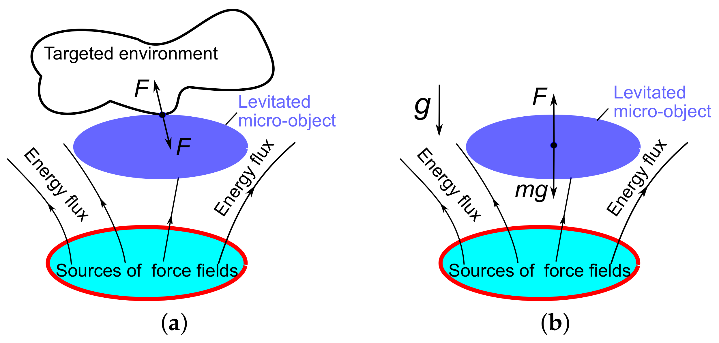
Figure 2.
Electric levitation micro-actuators based on the passive levitation: (a) single-stator design; (b) dual-stator design; (c) levitation of a charged particle in a hyperbolic oscillating electric field E (U is the applied electric potential).
Figure 2.
Electric levitation micro-actuators based on the passive levitation: (a) single-stator design; (b) dual-stator design; (c) levitation of a charged particle in a hyperbolic oscillating electric field E (U is the applied electric potential).

Figure 3.
Magnetic levitation micro-actuators (I is the electric direct current (DC)): (a) square coil design for micro-assembly [42]; (b) set of coils for a linear actuator [44].
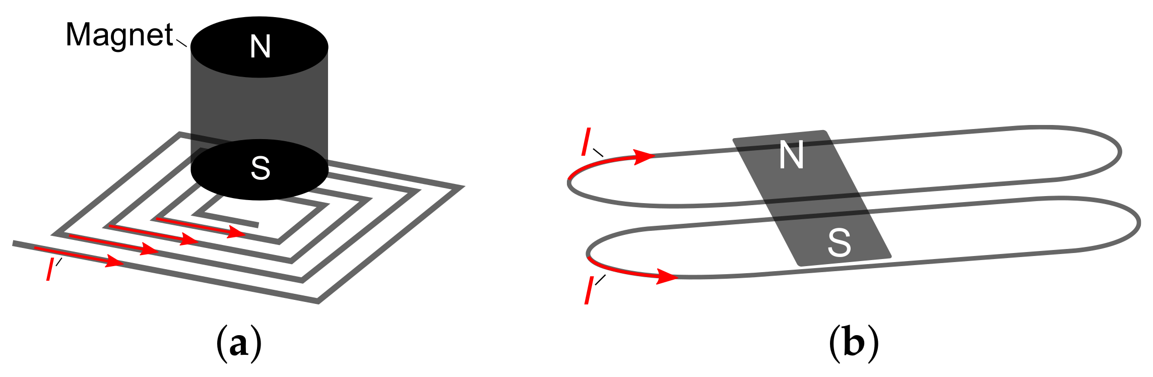
Figure 4.
Inductive levitation micro-actuators: (a) two coils design, I is the electric alternate current (AC) [47]; (b) spiral coil design [52]; (c) two racetrack-shaped solenoidal 3D wire-bonded micro-coils [17].

Figure 5.
Diamagnetic levitation micro-actuators: (a) two magnet design for levitation of droplet/particle [61,62,65,66]; (b) four magnet design for levitation of a plate [67,68]; (c) the design with a ring and disc shaped magnets [69,70].
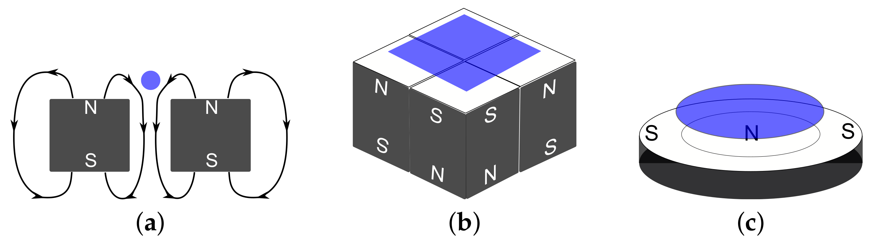
Figure 6.
Schematic of a highly focused laser beam to create an optical trap and levitate particles or micro-objects. Particles or micro-objects of arbitrary shape (sphere, cross and rod) can be trapped in an optical trap.
Figure 6.
Schematic of a highly focused laser beam to create an optical trap and levitate particles or micro-objects. Particles or micro-objects of arbitrary shape (sphere, cross and rod) can be trapped in an optical trap.


Table 1.
Levitating micro-actuators.
| Types of Actuator | Sources of Force Field | Materials of Levitated Mass/Rotor | Applications | Technologies | Ref. |
|---|---|---|---|---|---|
| Active | |||||
| Electric | Electrical | Dielectric, | Suspension | Bulk | [22,23,24,41] |
| field | Semiconductors | Accelerometer | Exotic Ball- | ||
| and conductive | micromaching | [36,37] | |||
| material | Motor | Bulk- | [25,27,28,29] | ||
| Gyroscope | micromaching | [26,30,31,32,33] | |||
| Multi-sensor | [34,35] | ||||
| Acelerometer | [38,39] | ||||
| Magnetic | DC current | Magnet | Actuator | Surface- | |
| micromaching | [42,43,44,45] | ||||
| Iron | Motor | Milli-machining | [46] | ||
| Passive | |||||
| Electric | Electrical | Conductive | Suspension | Surface- | |
| field | material | micromaching | [21] | ||
| Particles | Trapping | Mix of micromaching | |||
| and Bulk | [40] | ||||
| Inductive | Actuator | [47,52] | |||
| Gyroscope | Surface- | ||||
| AC current | Conductive | Motor | micromaching | [50,51] | |
| material | Suspension | [48,49] | |||
| 3D-micro-coil | [53,54,55,56,58,59,60] | ||||
| Diamagnetic | Trapping, Digital | Mix of Surface- | [61,62,65] | ||
| micro-fluidic | micromaching | [63,64,66] | |||
| Magnet | Diamagnetic | Accelerometer | and Bulk | [67,68] | |
| Gyroscope | [69,70] | ||||
| Force-sensor | [71] | ||||
| Supercon- | Magnet | Superconductor | Micro-bearing | Surface- | |
| ducting | micromaching | [73,74] | |||
| Optical | Light | Dielectric | Trapping, Rotation, | Precision mechanics | |
| Microfluidics, | Two Photon | [106,114,115,116,117,118,119,120,121,127] | |||
| Biochips, | Lithography | ||||
| Lab-on-Chip | |||||
| Hybrid | |||||
| Diamagnetic- | Magnet- | Diamagnetic | Trapping | Mix of Surface- | [128] |
| Electrostatic | electric field | Motor | micromaching | [129,130] | |
| Gyroscope | and Bulk | ||||
| Diamagnetic- | Magnet- | Diamagnetic- | |||
| Inductive | AC current | Conductive | [131] | ||
| material | |||||
| Electrostatic- | Electric | Conductive | Suspension, | Mix of Surface- | |
| Inductive | field- | material | Transporter | micromaching | [125] |
| AC current | and 3D-micro-coil | [17,123,124] | |||
| Accelerator | Surface- | ||||
| Accelerator | micromaching | [126,132] |
© 2018 by the authors. Licensee MDPI, Basel, Switzerland. This article is an open access article distributed under the terms and conditions of the Creative Commons Attribution (CC BY) license (http://creativecommons.org/licenses/by/4.0/).
Share and Cite
MDPI and ACS Style
Poletkin, K.V.; Asadollahbaik, A.; Kampmann, R.; Korvink, J.G. Levitating Micro-Actuators: A Review. Actuators 2018, 7, 17. https://doi.org/10.3390/act7020017
AMA Style
Poletkin KV, Asadollahbaik A, Kampmann R, Korvink JG. Levitating Micro-Actuators: A Review. Actuators. 2018; 7(2):17. https://doi.org/10.3390/act7020017
Chicago/Turabian StylePoletkin, Kirill V., Asa Asadollahbaik, Ronald Kampmann, and Jan G. Korvink. 2018. "Levitating Micro-Actuators: A Review" Actuators 7, no. 2: 17. https://doi.org/10.3390/act7020017
Note that from the first issue of 2016, this journal uses article numbers instead of page numbers. See further details here.