
Measuring the Temperature Increase of an Ultrasonic Motor in a 3-Tesla Magnetic Resonance Imaging System

1
Institute of Biomaterials and Biomedical Engineering, University of Toronto, Rosebrugh Building, 164 College Street, Room 407, Toronto, ON M5S3G9, Canada
2
Division of Neurosurgery, The Hospital for Sick Children, 555 University Avenue, Room 1504, Toronto, ON M5G1X8, Canada
3
Department of Mechanical and Industrial Engineering, University of Toronto, 5 King’s College Road, Room 106, Toronto, ON M5S3G8, Canada
*
Author to whom correspondence should be addressed.
Actuators 2017, 6(2), 20; https://doi.org/10.3390/act6020020
Submission received: 18 January 2017
/
Revised: 29 May 2017
/
Accepted: 29 May 2017
/
Published: 6 June 2017
Abstract
:This paper aims to evaluate the temperature increase caused by a 3.0-T magnetic resonance imaging (MRI) system on an ultrasonic motor (USM) used to actuate surgical robots in the MRI environment. Four fiber-optic temperature sensors were attached to the USM. Temperature was monitored outside the five-Gauss boundary and then inside the bore for 20 min while the USM was powered on. The USM temperature was tested for two states of the scanner, “off” and “on”, by employing common clinical imaging sequences and echo planar imaging sequences. The USM showed a slight temperature increase while operating in the static field of the MRI. A considerable temperature increase (~10 °C) was observed when the scanner was on. The temperature increased to 60 °C, which is beyond the acceptable safe temperature and can result in thermal burns. Most of the temperature increase (80%) was due to effects of the static field on the motion of the rotating parts of the motor, while the remainder (20%) derived from heat deposited in the conductive components of the USM due to radiofrequency pulses and gradient field changes. To solve the temperature increase, the metal components of the USM’s case can be replaced by silicon carbide.
1. Introduction
After an incident where a cardiovascular catheter melted during the monitoring of a patient in a magnetic resonance imaging (MRI) system [1], there have been serious concerns pertaining to the use of surgical tools during MRI scanning. More than 70% of MRI injuries have been due to thermal burns [2]. Many types of burns have been reported due to heat induced by the MRI system in devices while they are being inappropriately used during MR procedures [1].
MRI has numerous advantages over other imaging modalities. It provides high-resolution three-dimensional (3D) images, which are considered the best modality for both detecting tumors [3,4] and removing them without ionizing radiation. MRI provides excellent contrast of soft tissues, which can avoid trauma to critical structures during surgery [5]. It is an ideal modality for real-time image-guided interventions because it provides precise, updated spatial information of the target tissue, including its deflection at any orientation with a rapid image acquisition time [6,7,8]. Additionally, it can extract functional parameters, such as temperature distribution and blood velocity [9]. These capabilities strongly motivate the development of MRI-compatible technology that can leverage the imaging techniques and robotic devices.
Ultrasonic motors (USMs) are a common type of MRI-compatible actuator that have been used in the development of many surgical tools. Surgical tools that currently use USMs as actuators include needle insertion manipulators for stereotactic neurosurgery [10], MRI-compatible robot-assisted surgical systems for prostatic interventions (MRI-P) [11], transrectal prostate robots [12], robotic systems to perform microwave-thermocoagulation [13], a robot for laparoscopic surgeries [14], a neuroArm for neurosurgery [15], a robotic system for minimally invasive breast surgery [13], and a telerobotic device developed for computer tomography and MRI-guided interventions [16].
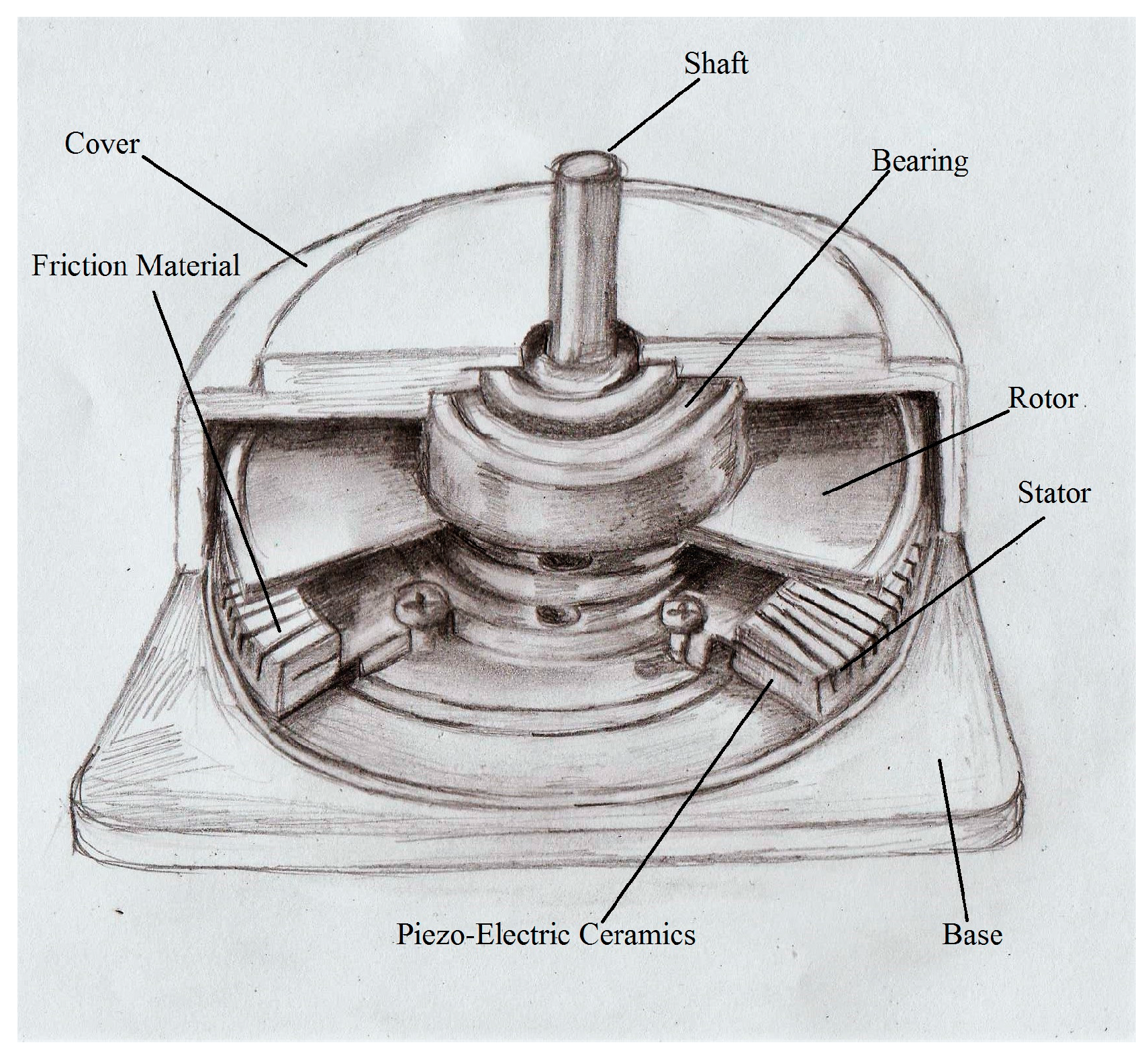
Ultrasonic motors are a class of rotary type piezoelectric actuators known as harmonic motors. They operate at a high voltage (approximately 200–300 V). Since the operating frequency of this motor is located in the ultrasonic range (25 to 70 KHz), this type of motor is referred to as an “ultrasonic motor”. The type of motor considered in this research is the ring-type piezoelectric travelling wave rotary ultrasonic motor. Two sinusoidal signals with a 90° phase difference drive the motors at a speed adjusted by the amplitude of these signals [17]. These waves resonate and propagate a wave into the stator. The propagation of the rotary wave into the ceramics of the stator is converted into the mechanical motion of the rotor by a friction mechanism. The rotational direction depends on the lead or lag of the input signals. In an ideal case, the generated power would be equal for both rotational directions; i.e., clockwise (CW) and counter clockwise (CCW).
The two main actuating parts of the motor are the stator and rotor. In addition to these parts, the case and shaft comprise the full structure of the motor, which is illustrated in Figure 1. The Shinsei ultrasonic motor and Piezoelectric Ultrasonic Motor of Rotary (PUMR) series are commonly used in the MRI-compatible surgical robots hitherto developed.
Ultrasonic motors have certain advantages, such as large torque [19], high holding torque (approximately 1.0 Nm) [20], compactness, lightness, zero backlash, an ability to operate in a strong magnetic field [21], absence of a generated magnetic field, quiet operation, simple structure [19], fast dynamic response, and high efficiency [21].
Despite the above benefits, USMs are limited by their nonlinear behaviors and short life spans [21]. They contain conductive materials [20], such as a metal ring in the stator, which is required for exciting the piezoceramic materials, and a metallic case for dissipating heat generated by friction between the motor and stator. These conductive materials cause a temperature increase when they interact with MRI fields. Radio frequency pulses and gradient fields are able to induce heating in conductive objects. Eddy currents induced by changing magnetic fields flow through a conductor and heat is generated due to resistance.
The high temperature of the motor near a patient is associated with a safety risk due to possible thermal burn. The motor temperature can reach up to 120 °C, which may result in melting of the plastic components near the motor or attached to the shaft. Furthermore, the temperature increase seriously degrades the motor output characteristics and therefore the motor performance [22]. The generated torque is also affected by the temperature increase because the motor operates on a friction-based mechanism [23]. In addition, the speed is temperature sensitive; a temperature increase results in a decrease in speed [24]. The MRI’s magnetic fields induce eddy currents into the motor’s conductive materials. In addition, magnetic fields may interact with the motor and change the mechanical motion of the rotor operation via a friction-based mechanism. This interaction may change the temperature of the motor and affect motor output performance.
Heating effects of the MRI on the USM have not been fully studied and could be of great interest, as temperature change is a factor that affects the output characteristics of the motor such as speed and torque. Quantifying the impact of the MRI on the motor’s temperature is therefore of great interest and is the focus of this research.
The experimental protocol is explained in the methodology section. The results of the temperature increase when common clinical MRI sequences are applied, as well as the results of evaluating the sources of temperature increase, are reported in the results section. The sources of the temperature increase and a comparison with previous studies are provided in the discussion section. The conclusions section provides a brief conclusion of this research.
2. Materials and Methods
A USM (PUMR 40E, Piezoelectric Technology Co., Ltd., Seoul, Korea) shown in Figure 2 was used in this research. The motor’s dimensions are approximately of 454525 mm3. The cylindrical motor’s shaft has a diameter and length of approximately 2 and 20 mm, respectively.
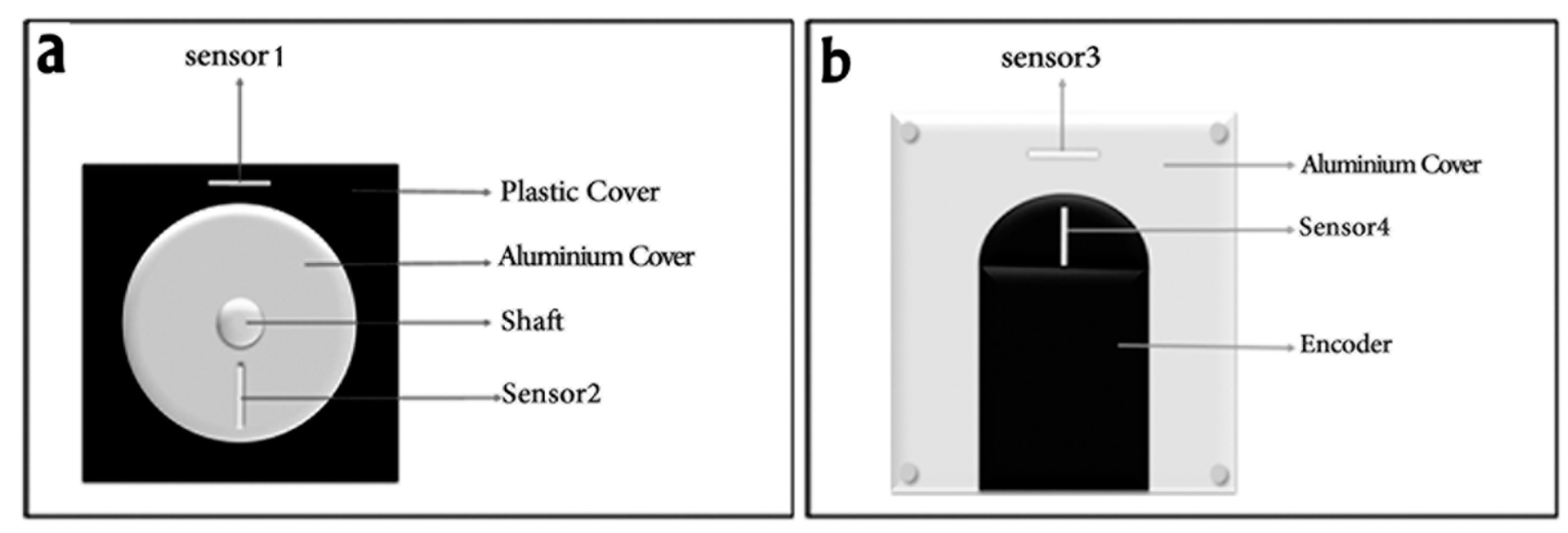
Four fiber optic temperature sensors (Neoptix Inc., Mississauga, ON, Canada) were attached to measure its temperature while operating at 75% of its maximum speed. Sensor 1 was on the plastic cover of the motor case at the front, Sensor 2 was on the aluminum cover of the motor case at the front, Sensor 3 was on the aluminum cover of the motor case at the back, and Sensor 4 was on the encoder case attached at the back of the motor. Sensor placement is shown in Figure 3.
The temperature signals of the four sensors were first recorded when the motor was off and located outside the five-Gauss line of the MRI scanning room of a 3.0 Tesla Achieva (Philips Medical Systems, Best, the Netherlands). The scanner’s bore has a diameter and length of 60 and 100 cm, respectively. The motor was located at the center of bore in these experiments. The temperature signals represented the temperature of the four parts of the motor structure at room temperature and were referred to as reference signals. Next, the motor was turned on and signals were recorded three times outside the five-Gauss line for 20 min. The signals of this case were referred to as outside signals.
Sufficient time between each run was given to allow the motor temperature to reach room temperature. The motor was placed into the scanner in the y orientation (Figure 4), and the test was repeated while the scanner was off and the motor was on.
Finally, the operating motor was tested while the scanner was on, using four common clinical sequences: T1-weighted spin echo (T1W), T2-weighted turbo spin echo (T2W), fast spin echo (TSE), and gradient echo (FFE), with the following parameters:
- T1W: TE = 10 ms, TR = 0.60 s, FOV = 160 160 150 mm3, in-plane voxel size = 1 mm, slice thickness = 5 mm, and flip angle = 70°.
- T2W: TE = 80 ms, TR = 3 s, FOV = 160 160 150 mm3, in-plane voxel size = 1 mm, slice thickness = 5 mm, flip angle = 90°, and turbo factor = 5.
- TSE: TE = 72 ms, TR = 4 s, FOV = 160 160 150 mm3, in-plane voxel size = 1 mm, slice thickness = 5 mm, flip angle = 90°, and turbo factor = 16.
- FFE: TE = 2.8 ms, TR = 12.1 ms, FOV = 160160150 mm3, in-plane voxel size = 1 mm, slice thickness = 5 mm, and flip angle = 30°.
where TE is the echo time, TR is the repetition time, and FOV is the field of view.
The signals recorded in the case where the motor was placed inside the magnet bore were referred to as inside signals. The common time interval range of an MRI scan is reported between 15 [25] and 60 min [1]. A 20-min interval was selected to avoid damage to the motor, as USMs have a short lifetime. The temperature was recorded at a rate of one sample per second.
As the source of the temperature increase can be due to either the effect of the MRI on the mechanical motion of the rotor and shaft or the induction of eddy currents into the conductive motor components, the motor was tested while the scanner was off and on. First, the temperature was monitored when the motor was operating inside the static field and the scanner was off. Next, the temperature was monitored while applying common clinical image sequences, i.e., while the scanner was on. In addition, Echo Planar Imaging (EPI) sequences were applied because they employ rapidly reversing gradient fields that induce eddy currents.
In order to reduce the USM’s temperature increase, the conductive components of the motor case should be replaced by an MRI-compatible material with proper thermal conductivity. Silicon carbide was reported to have high thermal conductivity [26]. In order to identify its MRI-compatibility, a circular sheet of silicon carbide with a diameter of 20 cm and a thickness of 1 mm was scanned by applying common clinical image sequences (T1W, T2W, TSE, and FFE).
3. Results
3.1. Theoretical Evaluation
The temperature change can be estimated using Equation (1) [27].
where is the specific absorption rate (W/kg), is the specific heat of a lossy medium (J/kg·°C), is the temperature raise, and is the duration of the applied radio frequency (RF) pulse.
The maximum SAR for the used sequences was approximately 0.9 W/kg, which was for the balanced-FFE sequence. The specific heats of aluminum and brass are 900 and 375 J/kg·°C, respectively. If the motor is exposed to RF pulses for 20 min, the temperature increase is approximately 1.2 °C and 2.9 °C for aluminum and brass, respectively.
3.2. Scanner Off
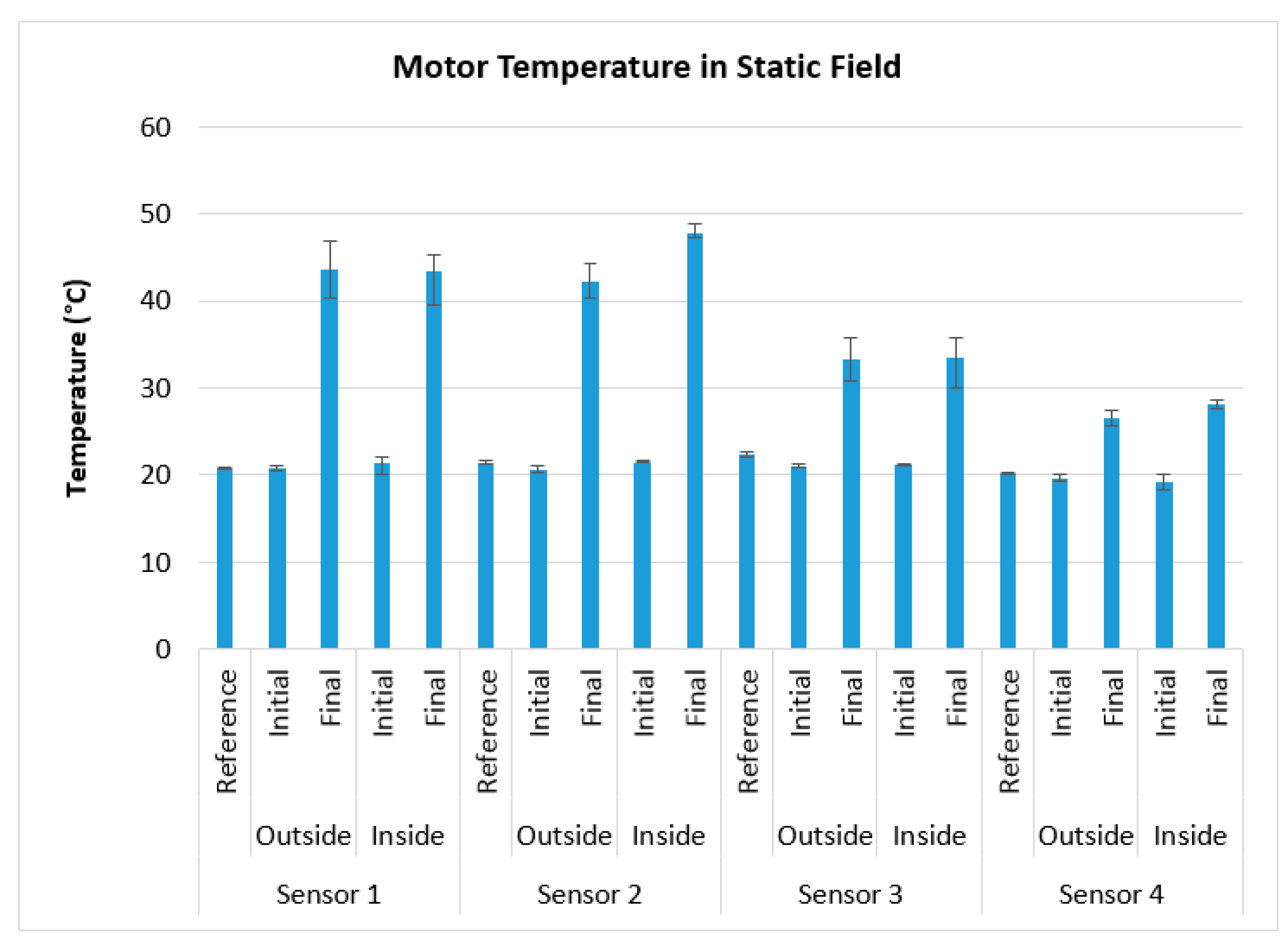
The driving conditions were as follows: the driving voltage was 120 V, the driving frequency was in the range of 34 to 37 KHz, and the energy supply was an AC voltage source. The initial value of the recorded temperature and the final value after 20 min are plotted in Figure 5. In this figure, the reference temperature refers to the room temperature recorded for each sensor. The outside temperatures refer to the signals recorded outside the five-Gauss line when the motor was on. The inside temperatures refer to the signals collected with the motor located inside the bore. The error bars show the minimum and maximum recorded temperatures. A temperature increase of 13% was observed on Sensor 2. A comparison of the outside and inside final temperatures showed that the temperature increase for the other sensors was trivial.
3.3. Scanner on Common Clinical Imaging Sequences
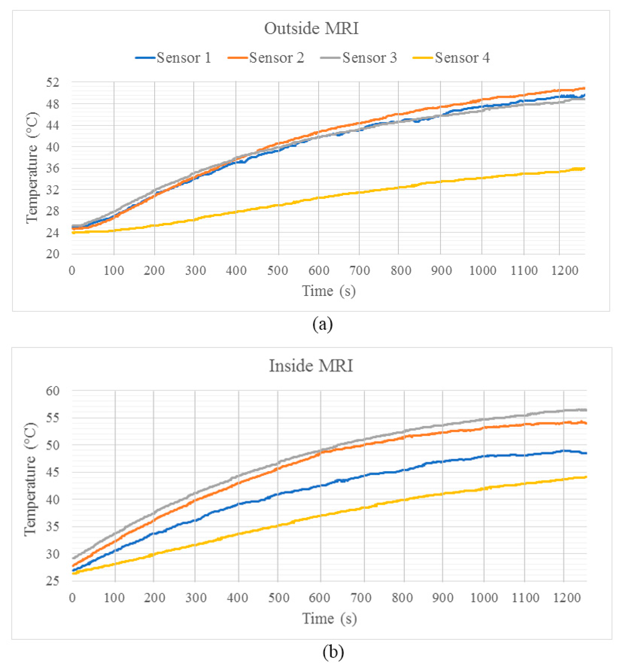
Figure 6 shows the USM temperature increase while the motor and scanner were on for 20 min. Figure 6a illustrates the temperature when the motor in the on state was placed outside the five-Gauss line. Figure 6b shows the data when the motor was placed inside the scanner and the four common clinical sequences were employed. The temperature increased by approximately 10 °C while the motor was operating in the MRI system, reaching 60 °C while common clinical imaging sequences were being applied in the MRI system.
3.4. Scanner on Echo Planar Imaging Sequence
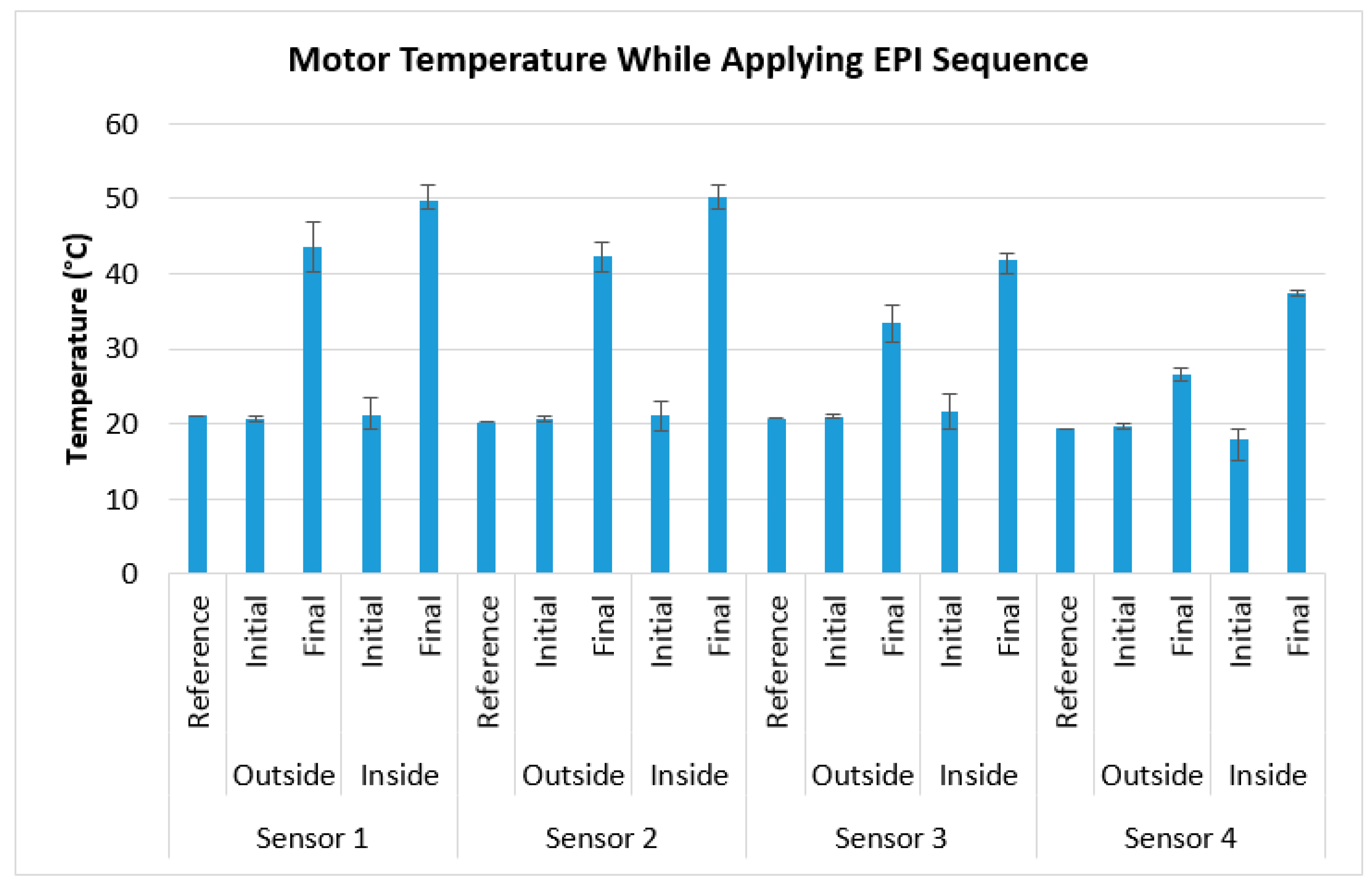
Figure 7 illustrates the temperature of the operating motor inside the bore while applying EPI sequences. In this case, the reference refers to the room temperature recorded for each sensor. The outside temperatures refer to the signals recorded outside the five-Gauss line when the motor was on. The inside temperatures refer to the signals collected with the motor located inside the bore. The error bars show the minimum and maximum recorded temperatures. Temperature increases of 14.2%, 18.8%, 25.6%, and 40.4% were observed for Sensor 1, Sensor 2, Sensor 3, and Sensor 4, respectively.
3.5. MR Image of Silicon Carbide
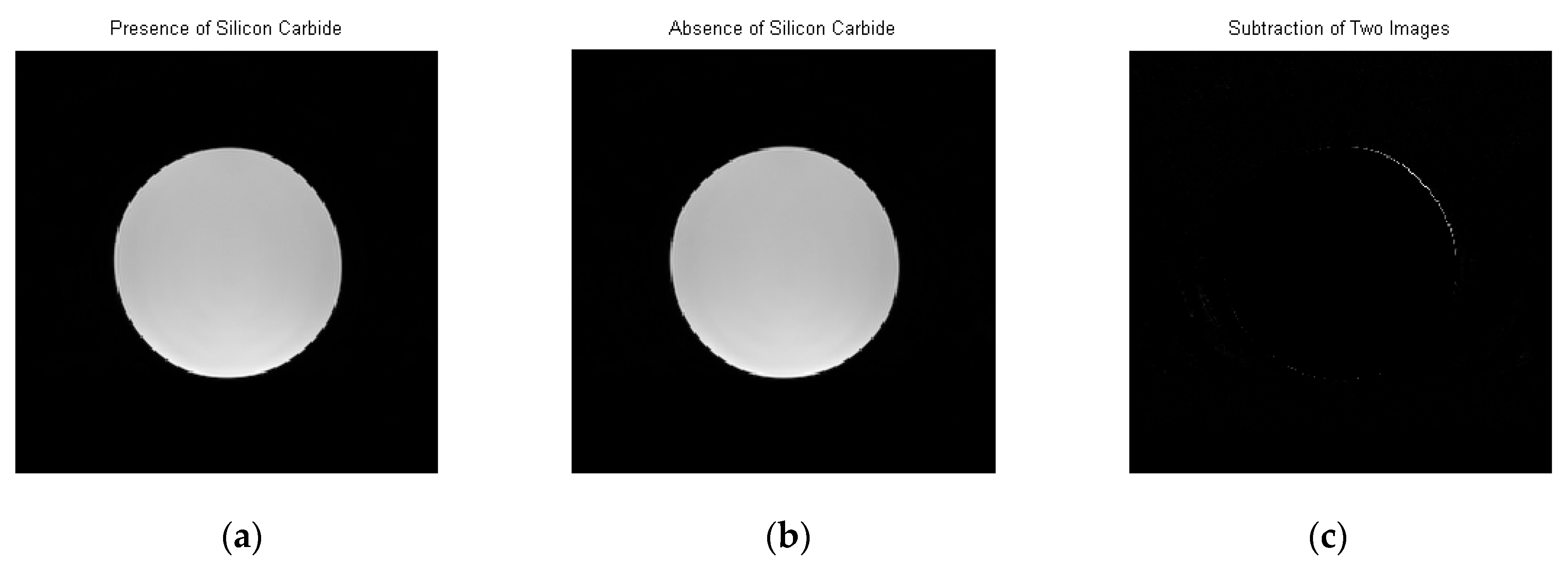
The sheet of silicon carbide showed insignificant image artifacts in all applied image sequences. Figure 5 illustrates this fact when T2W was applied. The left image of Figure 8 illustrates the transverse scan of the phantom in the presence of the silicon carbide sheet located at the top of image, and the center image shows the same scan in the absence of the sheet. Insignificant image artifact is observed by comparing these two images.
4. Discussion
The temperature of the motor does not significantly change when the motor is operating inside the static field, except for Sensor 2. The increase of 13% for Sensor 2 is due to the effects of the MRI field on the mechanical motion of the shaft. The induced magnetic force into the moving brass shaft is due to the electromotive force induction of the static magnetic field. The static magnetic field opposes the motion of the shaft, which is connected to the rotor and then to the stator. This opposition force may affect the friction mechanism between the rotor and stator, generating friction and heat. This force acts as a negative force and generates heat, resulting in power loss from the motor. This phenomenon can be explained using Faraday’s law.
The use of bearings for shaft rotation may reduce this effect. Therefore, other sources of heat generation may exist, such as the direct effect of the magnetic field on the piezoelectric material. The efficiency for stator excitation may decrease by being exposed to a large magnetic field. The internal electric field required for excitation of the material may change, or the magnetic field may affect the profile of input signals, resulting in inefficiency of the piezoelectric material and the generation of increased friction and heat.
The temperature increase of approximately 10 °C across all results is in part due to the effect of the gradient fields and RF pulses. If the temperature rises to 60 °C, it is beyond the acceptable safe limit and can result in thermal burns. It has been reported that a temperature of approximately 60 °C can cause thermal burns within 3 s [28]. These fields result in the induction of eddy currents in the conductive components of the motors. The shape and material of the conductors are important factors that determine the magnitude of the induced eddy current. The eddy currents induced in small parts such as screws can be ignored due to their small size relative to those of other components, such as the aluminum cover on the front and rear cases of the motor. These conductive materials were used for heat dissipation of the motor because it operates via a friction mechanism between the stator and rotor.
The temperature increase of approximately 10 °C in all results is also in part due to the effects of the MRI field on mechanical motion of the shaft. A comparison of the theoretical and experimental values shows that 20% of the temperature increase is due to RF deposition energy and 80% is due to the effects on mechanical motion. In addition, the temperature increase affects characteristics of the motor output, such as speed. For safety purposes, it can be concluded that the duration of motor operation should be limited to approximately 10 min.
The comparison with the temperature increase in the EPI test results shows that most of the deposited energy is contained in the aluminum plate of the motor’s rear case, which is larger than the other conductive parts of the motor. The gradient field changes in these sequences deposit most of the energy into the conductive parts of the case.
In solving the problem of a USM’s temperature increase due to interaction with MRI, the conductive materials of the case can be replaced by silicon carbide. Silicon carbide is an effective substitution for this material because of its high thermal conductivity and trivial image artifacts.
5. Conclusions
Using a 3.0-T MRI system, a considerable temperature increase (approximately 10 °C) is observed in the motor, affecting speed and raising temperatures to 60 °C, which is beyond the acceptable safe temperature and can result in thermal burns. The temperature increase due to the static field affects the motion of the motor’s rotating part, namely the brass shaft. Part of the heat is deposited in the motor’s conductive components as a result of the RF pulses and gradient field changes. A significant part of the deposited energy is transferred to the aluminum components of the motor’s rear case. Silicon carbide is an effective substitution for the conductive materials of a USM case, owing to its high thermal conductivity and insignificant effect on the MR images.
Heat may be generated as an adverse effect of the scanner’s magnetic field on piezoelectric materials and inefficient energy conversion in these materials. However, this temperature increase can be resolved with no significant effect on the MR images by replacing the conductive materials of the USM case with silicon carbide. Due to the temperature increase, safe operation of the USM is limited to 10 min.
Acknowledgments
This work was supported financially by A. A. Goldenberg's Natural Sciences and Engineering Research Council of Canada (NSERC)—Collaborative Health Research Projects (CHRP) Grant 385860-10. In addition, the authors would like to thank Adam Waspe for his technical support and Bruceoathsman Thevakumaran for drawing Figure 1.
Author Contributions
Peyman Shokrollahi conceived and designed the experiments; Peyman Shokrollahi performed the experiments; Peyman Shokrollahi analyzed the data; James M. Drake and Andrew A. Goldenberg contributed reagents/materials/analysis tools; Peyman Shokrollahi wrote the paper.
Conflicts of Interest
The authors declare no conflict of interest. The founding sponsors had no role in the design of the study; in the collection, analyses, or interpretation of data; in the writing of the manuscript, and in the decision to publish the results.
References
- Shellock, F.G.; Shellock, V.J. Cardiovascular catheters and accessories: Ex vivo testing of ferromagnetism, heating, and artifacts associated with MRI. J. Magn. Reson. Imaging 1998, 8, 1338–1342. [Google Scholar] [CrossRef] [PubMed]
- The Joint Commission. Preventing accidents and injuries in the MRI suite. J. Radiol. Nurs. 2008, 27, 74–77. [Google Scholar]
- Stoianovici, D.; Song, D.; Petrisor, D.; Ursu, D.; Mazilu, D.; Muntener, M.; Schar, M.; Patriciu, A. “MRI Stealth” robot for prostate interventions. Minim. Invasive Ther. Allied. Technol. 2007, 16, 241–248. [Google Scholar] [CrossRef] [PubMed]
- Chinzei, K.; Hata, N.; Jolesz, F.A.; Kikinis, R. Surgical assist robot for the active navigation in the intraoperative MRI: Hardware design issues. In Proceedings of the 2000 IEEE/RSJ International Conference on Intelligent Robots and Systems, Takamatsu, Japan, 30 October–5 November 2000. [Google Scholar] [CrossRef]
- Koseki, Y.; Washio, T.; Chinzei, K.; Iseki, H. Endoscope manipulator for trans-nasal neurosurgery, optimized for and compatible to vertical field open MRI. Med. Image Comput. Comput. Assist. Interv. 2002, 2488, 114–121. [Google Scholar]
- Tsekos, N.V.; Khanicheh, A.; Christoforou, E.; Mavroidis, C. Magnetic resonance-compatible robotic and mechatronics systems for image-guided interventions and rehabilitation: A review study. Annu. Rev. Biomed. Eng. 2007, 9, 351–387. [Google Scholar] [CrossRef] [PubMed]
- Elhawary, H.; Tse, Z.T.H.; Hamed, A.; Rea, M.; Davies, B.L.; Lamperth, M.U. The case for MR-compatible robotics: A review of the state of the art. Int. J. Med. Robot. Comput. Assist. Surg. 2008, 4, 105–113. [Google Scholar] [CrossRef] [PubMed]
- Wong, T.Z.; Schwartz, R.B.; Pergolizzi, R.S., Jr.; Black, P.M.; Kacher, D.F.; Morrison, P.R.; Jolesz, F.A. Interactive MR image guidance for neurosurgical and minimally invasive procedures. Proc. SPIE 1999, 3594, 170–177. [Google Scholar]
- Kaiser, M.; Krug, J.; Rose, G. Interventional MRI: Minimal-invasive surgery under MR guidance. In Proceedings of the 2011 IEEE MTT-S International Microwave Symposium Digest (MTT), Baltimore, MD, USA, 5–10 June 2011. [Google Scholar] [CrossRef]
- Masamune, K.; Kobayashi, E.; Masutani, Y.; Suzuki, M.; Dohi, T.; Iseki, H.; Takakura, K. Development of an MRI-compatible needle insertion manipulator for stereotactic neurosurgery. J. Image Guid. Surg. 1995, 1, 242–248. [Google Scholar] [CrossRef]
- Goldenberg, A.A.; Trachtenberg, J.; Yi, Y.; Weersink, R.; Sussman, M.S.; Haider, M.; Ma, L.; Kucharczyk, W. Robot-assisted MRI-guided prostatic interventions. Robotica 2010, 28, 215–234. [Google Scholar] [CrossRef]
- Krieger, A.; Iordachita, I.; Song, S.E.; Cho, N.B.; Guion, P.; Fichtinger, G.; Whitcomb, L.L. Development and preliminary evaluation of an actuated MRI-compatible robotic device for MRI-guided prostate intervention. In Proceedings of the 2010 IEEE International Conference on Robotics and Automation (ICRA), Anchorage, AK, USA, 3–7 May 2010; pp. 1066–1073. [Google Scholar]
- Larson, B.T.; Erdman, A.G.; Tsekos, N.V.; Yacoub, E.; Tsekos, P.V.; Koutlas, I.G. Design of an MRI-compatible robotic stereotactic device for minimally invasive interventions in the breast. J. Biomech. Eng. 2004, 126, 458–465. [Google Scholar] [CrossRef] [PubMed]
- Hashizume, M.; Yasunaga, T.; Tanoue, K.; Ieiri, S.; Konishi, K.; Kishi, K.; Nakamoto, H.; Ikeda, D.; Sakuma, I.; Fujie, M.; et al. New real-time MR image-guided surgical robotic system for minimally invasive precision surgery. Int. J. Comput. Assist. Radiol. Surg. 2008, 2, 317–325. [Google Scholar] [CrossRef]
- Sutherland, G.R.; McBeth, P.B.; Louw, D.F. NeuroArm: An MR compatible robot for microsurgery. Int. Congr. Ser. 2003, 1256, 504–508. [Google Scholar] [CrossRef]
- Hempel, E.; Fischer, H.; Gumb, L.; Höhn, T.; Krause, H.; Voges, U.; Breitwieser, H.; Gutmann, B.; Durke, J.; Bock, M.; et al. An MRI-compatible surgical robot for precise radiological interventions. Comput. Aided Surg. 2003, 8, 180–191. [Google Scholar] [CrossRef] [PubMed]
- Cole, G.A.; Harrington, K.; Su, H.; Camilo, A.; Pilitsis, J.G.; Fischer, G.S. Closed-Loop Actuated Surgical System Utilizing Real-Time In-Situ MRI Guidance. In Experimental Robotics; Springer: Berlin/Heidelberg, Germany, 2014; pp. 785–798. [Google Scholar]
- Shinsei Corporation. 2007. Available online: http://www.shinsei-motor.com/English/techno/ultrasonic_motor.html (accessed on 10 May 2017).
- Hirata, H.; Ueha, S. Characteristics estimation of a traveling wave type ultrasonic motor. IEEE Trans. Ultrason. Ferroelectr. Freq. Control. 2002, 40, 402–406. [Google Scholar] [CrossRef] [PubMed]
- Tsekos, N.V.; Shudy, J.; Yacoub, E.; Tsekos, P.V.; Koutlas, I.G. Development of a robotic device for MRI-guided interventions in the breast. In Proceedings of the IEEE 2nd International Symposium on Bioinformatics and Bioengineering, Bethesda, MD, USA, 4–6 November 2001; pp. 201–208. [Google Scholar]
- Bolborici, V. Modeling of the Stator of Piezoelectric Traveling Wave Rotary Ultrasonic Motors. Ph.D. Thesis, University of Toronto, Toronto, ON, Canada, 2009. [Google Scholar]
- Uchino, K. Piezoelectric ultrasonic motors: Overview. Smart Mater. Struct. 1998, 7, 273–285. [Google Scholar] [CrossRef]
- Senjyu, T.; Miyazato, H.; Yokoda, S.; Uezato, K. Speed control of ultrasonic motors using neural network. IEEE Trans. Power Electron. 1998, 13, 381–387. [Google Scholar] [CrossRef]
- Zhao, C. Ultrasonic Motors: Technologies and Applications; Springer Science & Business Media: New York, NY, USA, 2011. [Google Scholar]
- Dedini, R.D.; Karacozoff, A.M.; Shellock, F.G.; Xu, D.; McClellan, R.T.; Pekmezci, M. MRI issues for ballistic objects: Information obtained at 1.5-, 3- and 7-Tesla. Spine J. 2013, 13, 815–822. [Google Scholar] [CrossRef] [PubMed]
- Slack, G.A. Thermal conductivity of pure and impure silicon, silicon carbide, and diamond. J. Appl. Phys. 1964, 35, 3460–3466. [Google Scholar] [CrossRef]
- Bassen, H.; Kainz, W.; Mendoza, G.; Kellom, T. MRI-induced heating of selected thin wire metallic implants—Laboratory and computational studies—Findings and new questions raised. Minim. Invasive Ther. Allied Technol. 2006, 15, 76–84. [Google Scholar] [CrossRef] [PubMed]
- Jeschke, M.G.; Kamolz, L.P.; Sjöberg, F.; Wolf, S.E. Handbook of Burns; Springer: Vienna, Austria; New York, NY, USA, 2012; p. 42. [Google Scholar]
Figure 1.
Structure of the ultrasonic motor described in [18].
Figure 1.
Structure of the ultrasonic motor described in [18].

Figure 2.
PUMR 40E, Piezoelectric Technology Co., Ltd., Seoul, Korea.
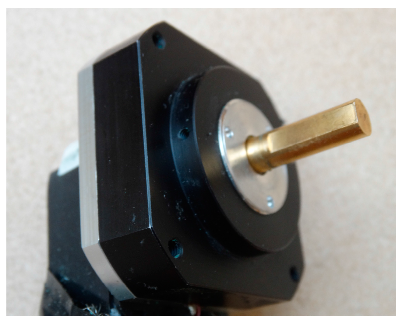
Figure 3.
Sensor locations: (a) Motor front view; (b) Motor rear view.

Figure 4.
The motor orientation with respect to the bore.
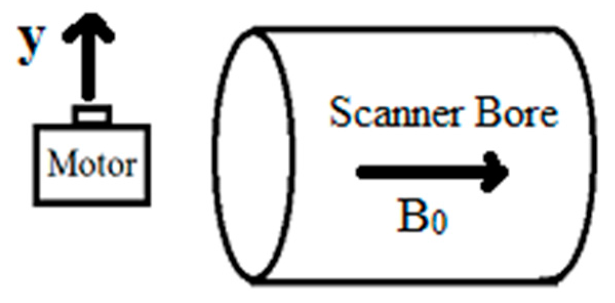
Figure 5.
Motor temperature increase in static field, when the scanner was off.

Figure 6.
(a) Temperature of the operating ultrasonic motor (USM) outside the magnetic resonance imaging (MRI) system; (b) Temperature of the operating USM inside the bore when the scanner was on.
Figure 6.
(a) Temperature of the operating ultrasonic motor (USM) outside the magnetic resonance imaging (MRI) system; (b) Temperature of the operating USM inside the bore when the scanner was on.

Figure 7.
Motor temperature increase while applying Echo Planar Imaging (EPI) sequences.

Figure 8.
(a) The T2-weighted turbo spin echo (T2W) transverse image of the phantom in the presence of silicon carbide sheet; (b) the same image in the absence of the sheet; (c) the subtraction of these two images (a,b).
Figure 8.
(a) The T2-weighted turbo spin echo (T2W) transverse image of the phantom in the presence of silicon carbide sheet; (b) the same image in the absence of the sheet; (c) the subtraction of these two images (a,b).
© 2017 by the authors. Licensee MDPI, Basel, Switzerland. This article is an open access article distributed under the terms and conditions of the Creative Commons Attribution (CC BY) license (http://creativecommons.org/licenses/by/4.0/).
Share and Cite
MDPI and ACS Style
Shokrollahi, P.; Drake, J.M.; Goldenberg, A.A. Measuring the Temperature Increase of an Ultrasonic Motor in a 3-Tesla Magnetic Resonance Imaging System. Actuators 2017, 6, 20. https://doi.org/10.3390/act6020020
AMA Style
Shokrollahi P, Drake JM, Goldenberg AA. Measuring the Temperature Increase of an Ultrasonic Motor in a 3-Tesla Magnetic Resonance Imaging System. Actuators. 2017; 6(2):20. https://doi.org/10.3390/act6020020
Chicago/Turabian StyleShokrollahi, Peyman, James M. Drake, and Andrew A. Goldenberg. 2017. "Measuring the Temperature Increase of an Ultrasonic Motor in a 3-Tesla Magnetic Resonance Imaging System" Actuators 6, no. 2: 20. https://doi.org/10.3390/act6020020
Note that from the first issue of 2016, this journal uses article numbers instead of page numbers. See further details here.