
Design and Evaluation of a Semi-Active Magneto-rheological Mount for a Wheel Loader Cabin

Department of Mechanical Engineering, Inha University, Incheon 402-751, Korea
*
Author to whom correspondence should be addressed.
Actuators 2017, 6(2), 16; https://doi.org/10.3390/act6020016
Submission received: 2 January 2017
/
Revised: 3 April 2017
/
Accepted: 18 April 2017
/
Published: 20 April 2017
(This article belongs to the Special Issue Magnetorheological Fluids, Devices, and Integrated Adaptive Systems)
Abstract
:In this study, a semi-active magneto-rheological (MR) mount is designed and manufactured to minimize unwanted vibrations for the cabin of heavy vehicles. Normally, working conditions in heavy vehicles are extremely rugged. Usually, the heavy vehicles use passive rubber mounts for the reduction of vibrations from road. However, the passive mount has definite performance limitations because the passive mount has a fixed resonance frequency when the design is finished. An MR application is one of the solutions because the viscosity of MR fluid can be controlled. As a first step, an experimental apparatus was established for performance evaluation of the mounts. The apparatus has hydraulic excitatory, force, and displacement sensors. Performance of two different passive mounts used in industrial fields were evaluated. The passive mount data of force-displacement, force-velocity, and displacement transmissibility were collected and tested. After that, an MR mount was designed and manufactured that provides better performance using the passive mount data. The MR mount uses two different flow paths, annular duct and radial channels, for generating the required damping force. The field-dependent damping forces were then evaluated with respect to the moving stroke and input current. In this work, in order to control the damping force, an on-off controller associated with the fast Fourier transform (FFT) was used. The control results of the MR mount were compared with the results of passive rubber mounts. It was shown that the semi-active MR mount can attenuate vibrations more effectively at all frequency ranges compared with the passive rubber mount.
1. Introduction
Heavy equipment vehicles, including wheel loaders, absolutely require suspension systems to protect workers from experiencing severe vibrations caused by several factors such as unbalanced tasks. As is well known, the wheel loader is specially manufactured as one of the heavy equipment vehicles used for the construction or mining industries. Therefore, the operators of the wheel loader are easily exposed to various impact and vibration sources that bring harmful effects to their bodies. There are two types of the effects according to the frequency and source of the vibrations [1]. When the operator is on a vibrating object with a frequency between 5 Hz and 80 Hz, called whole-body vibration, there is a high probability of injuring the lower back or the upper limbs. When the operator holds a vibrating object with a frequency between 6.3 Hz and 1250 Hz, called hand-transmitted vibration, the risk of hand-arm vibration syndrome or vascular disorders increases. Therefore, many health surveillance organizations restrict vibration exposure levels to protect workers by using specific vibration evaluation criteria [2,3]. In response to the regulations, heavy equipment vehicle industries try to develop or improve vibration isolators to follow the regulations and also to reinforce competitiveness of their product.
There are three types of suspension systems for vibration minimization of cabins; passive, active, and semi-active. The passive vibration isolator, which is made of passive materials such as rubber or air springs, is widely used because of its simplicity and economic feasibility [4,5]. However, inherent characteristics of passive suspension systems are not appropriate in construction equipment because they may amplify low-frequency vibrations which are critical to workers. Therefore, another type of vibration isolator is recommended to improve the vibration exposure rate of the operators. The active vibration isolator is composed of actuators such as pneumatic pumps or piezoelectric materials and can generate forces, or inject forces, into the system in the reverse direction to the passive isolator. Thus, the active vibration control system can achieve predominant performance, compared to the passive mount, and even reduce vibrations at low frequencies, which cannot be achieved by using the passive vibration isolator [6,7]. However, the active suspension system is costly due to the additional apparatus such as a power supply and a high-performance processor. Moreover, the active suspension system has a critical disadvantage: a malfunction of the controller destroys the stability of the system.
The semi-active system is generally realized by magneto-rheological (MR) fluid so as to minimize the vibrations. The inherent characteristics of the fluid, such as its viscoelastic properties, can be tuned by external stimuli such as magnetic fields [8,9,10]. Because the MR fluid has many benefits, such as fast response time, simple control strategy, and fail-safe conditions, MR applications are the most significant factors for vibration control systems. The applications of MR devices are used in various industrial fields, such as vehicle suspensions and mounts. Damper and mount can be designed by using MR fluid, and the MR damper and mount has a high device research capacity in vibration control areas. In the applications of MR fluid with dampers or mounts, three main operation modes of MR fluid are used: flow mode, shear mode, and squeeze mode [11,12]. In addition, an MR valve has been studied for a high-load engine mount using flow and shear mode [13,14]. Despite numerous research works on the applications of MR fluid in various fields, no research has been done on the vibration control with MR fluid for heavy vehicle systems such as a wheel loaders.
Consequently, the main technical contribution of this work is to develop a new semi-active MR mount for a wheel loader cabin. In addition, vibration control effect is compared with commercialized passive rubber mounts. As the first step, two different passive mounts, which are used in the wheel loader system, were experimentally evaluated, and an experimental apparatus was manufactured for the test. Then, a semi-active MR mount was designed and evaluated by using the experimental apparatus. All experimental results are presented and discussed in frequency domain.
2. Dynamic Characteristics of Passive Mounts
Most heavy vehicles are work on extreme road conditions with human operators in the cabin. The working time of humans when their bodies are exposed to vibration and shock is limited by ISO 2613-1. Whole body vibrations of low frequency greatly influence human health, and high frequency vibrations affects ride quality. Industrial fields normally use two types of viscous rubber mounts: hard and soft mounts. Figure 1 shows the commercial passive rubber mounts used on the wheel loader. The hard and soft rubber mounts are called viscous and cabsus mounts. Because the viscous mount has high stiffness and high damping force, it has good performance with low vibration conditions. However, the cabsus mount has low stiffness and low damping force. Therefore, the cabsus mount has opposite properties compared with those of the viscous mount.
In order to evaluate of the passive mounts, an experimental apparatus was established as shown in Figure 2. The apparatus was designed for two types of test. First, the mount was installed between the upper and lower plates for the damping force test. The upper plate is fixed and lower plate is forced to move with the sinusoidal excitation. The overall excitation system is controlled by the data acquisition (DAQ) board (dSPACE, DS1104 R&D Controller Board, dSPACE Ltd., Paderborn, Germany) which includes analog-to-digital (A/D) and digital-to-analog (D/A) signal converters. The input and output signals are measured by a linear variable differential transformer (LVDT) (FASTAR, FS3K, SENTECH INC, North Hills, CA, USA) and a load cell (PCB, M1203-03A, MTS Systems Corporation, Eden Prairie, MN, USA). The load cell is installed between the upper plate and a mount. All measured signals are transferred to the DAQ board and saved by a computer. Second, the upper plate is freely moved for transmissibility tests. For the test, 250 kg was installed on the upper plate because a quarter cabin model was considered.
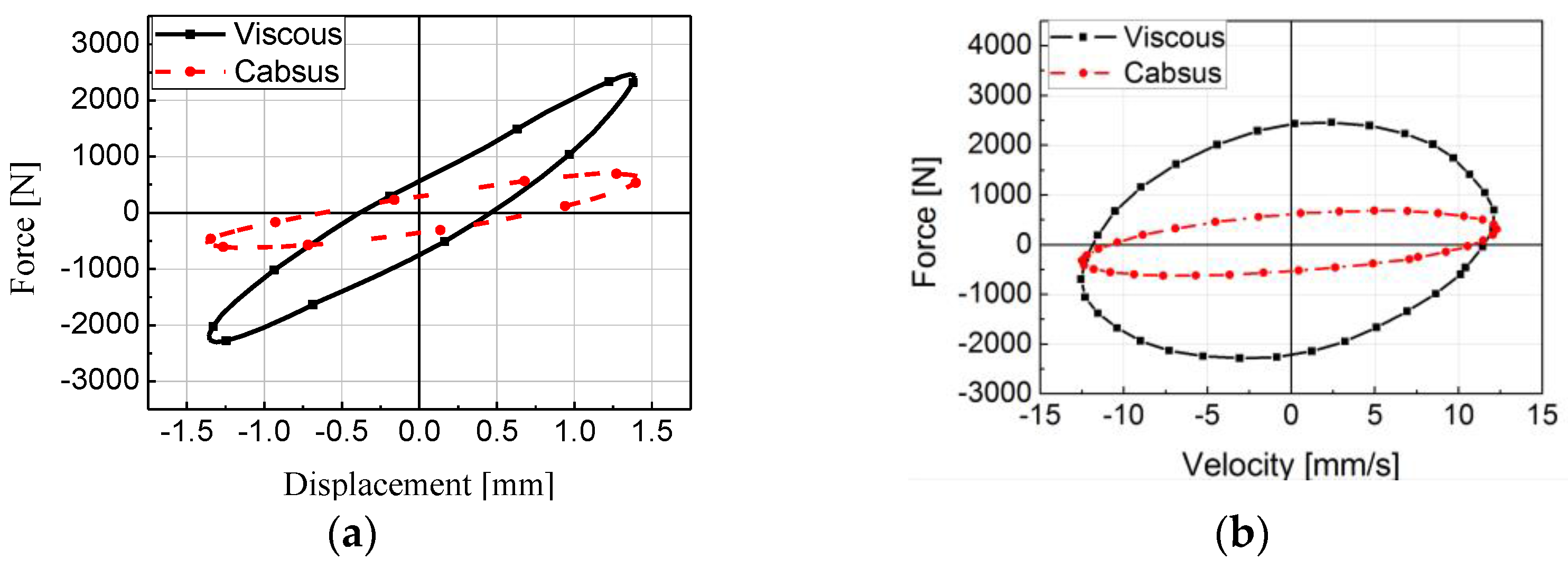
Figure 3 shows the force-displacement (F-D) and force-velocity (F-V) diagrams with the amplitude of 1.4 mm and 2 Hz sinusoidal excitation. The area of the F-D diagram indicates the energy dissipation. As shown in the Figure 3a, the energy dissipation of the viscous mount is bigger than that of the cabsus mount. Furthermore, the maximum damping force of the viscous and cabsus mounts are approximately 2400 N and 750 N at maximum velocity as shown in the Figure 3b. As shown in the results, the viscous and cabsus mounts have 1250 N/mm and 270 N/mm of the static stiffness, respectively. Furthermore, damping coefficients of the viscous and cabsus mounts are identified as 36.6 N·s/mm and 27.4 N·s/mm, respectively.
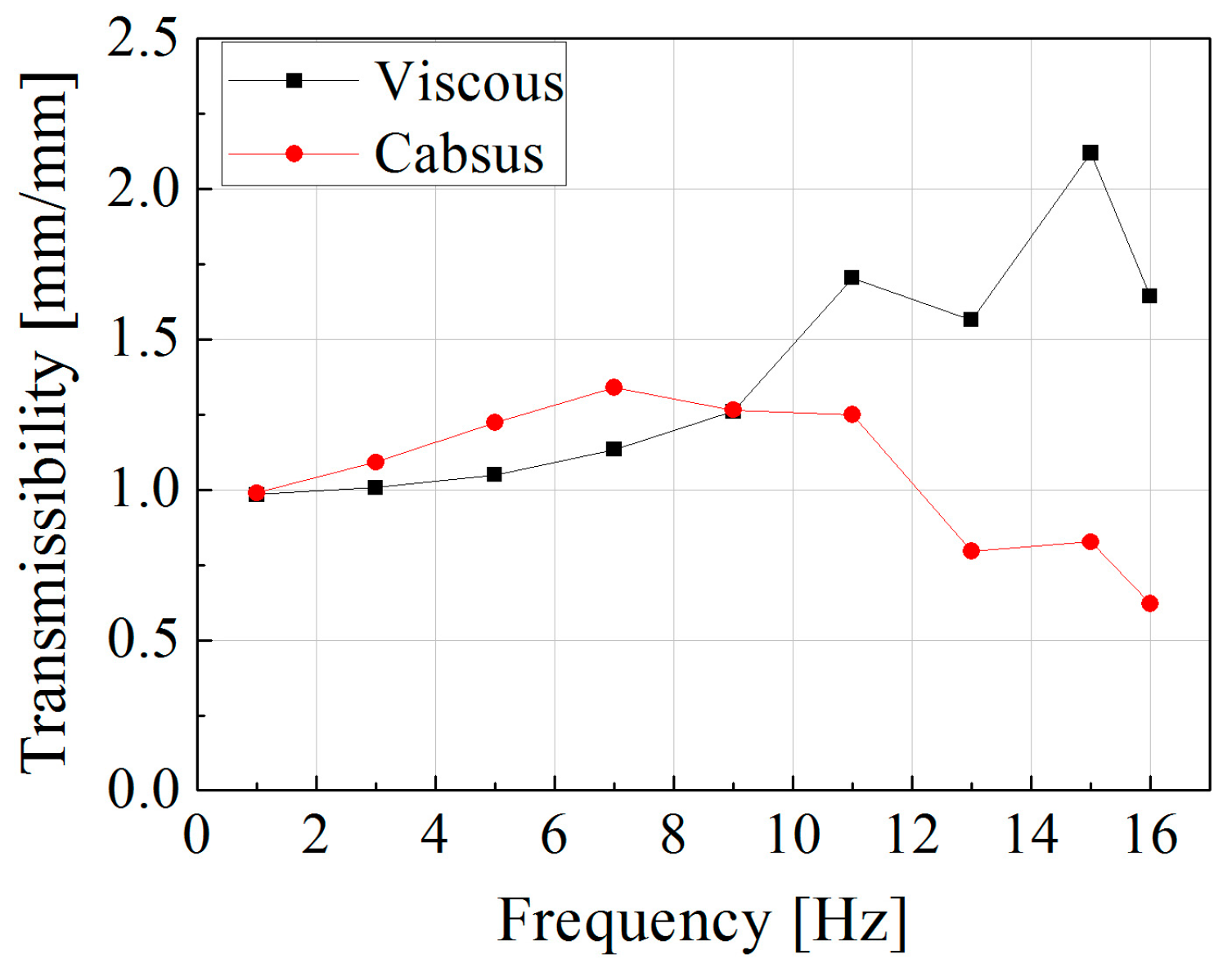
The displacement transmissibility of passive mounts is obtained by using the input and output vibration magnitude. The magnitude is measured by the LVDT and the rotary variable differential transformer (RVDT, Celesco, MTA-5E-5KC-MB, Celesco Transducer Products Inc., Chatsworth, CA, USA), which are installed at the vertical column. As is well known, the transmissibility is the ratio between the amplitude of response vibration and the excitation vibration at specific frequency. Although frequency of vibration is random, transmissibility analysis is generally used since it represents the tendency of vibrations with respect to the exciting frequency. When the input vibration is represented as the sinusoidal function , the cabin will vibrate as . In the case above, , , and are excitation amplitude, frequency, and amplitude of cabin vibration, respectively. Using the above points, transmissibility is derived as follows:
In the above, is called natural frequency and defined as . is called damping ratio and defined as . In Equation (1), all variables are constant and calculated with M, C, and K values except for . Figure 4 shows the experimental results of the transmissibility according to the two passive mounts.
Using the displacement data from the upper and lower plates, the fast Fourier transform (FFT) is executed to obtain the amplitude of the vibration. Then, the amplitude of the upper plate is divided by that of the lower plate. Owing to the limitations of the experimental apparatus with respect to the excitation frequency, the graph was plotted up to 16 Hz. Thus, the resonance with the viscous mount cannot be observed. However, the resonance frequency is expected to exist above 16 Hz according to the trend of the transmissibility. In addition, the resonance frequency of the cabsus mount was identified at approximately 8 Hz. Therefore, the transmissibility calculation using the force–displacement diagram is reasonably acceptable. The resonance problem can be solved by utilizing the cabsus mount from the results of the transmissibility of the viscous mount. Before the resonance frequency of the cabsus mount, the transmissibility of cabsus mount is higher than that of the viscous mount, and the transmissibility of the viscous mount is higher than that of the cabsus mount after the resonance frequency of the cabsus mount. Therefore, the resonance problem can be resolved by using the proposed MR mount because the mount has similar properties to the viscous mount at low frequencies and with the cabsus mount at high frequencies.
3. Design of MR Mount
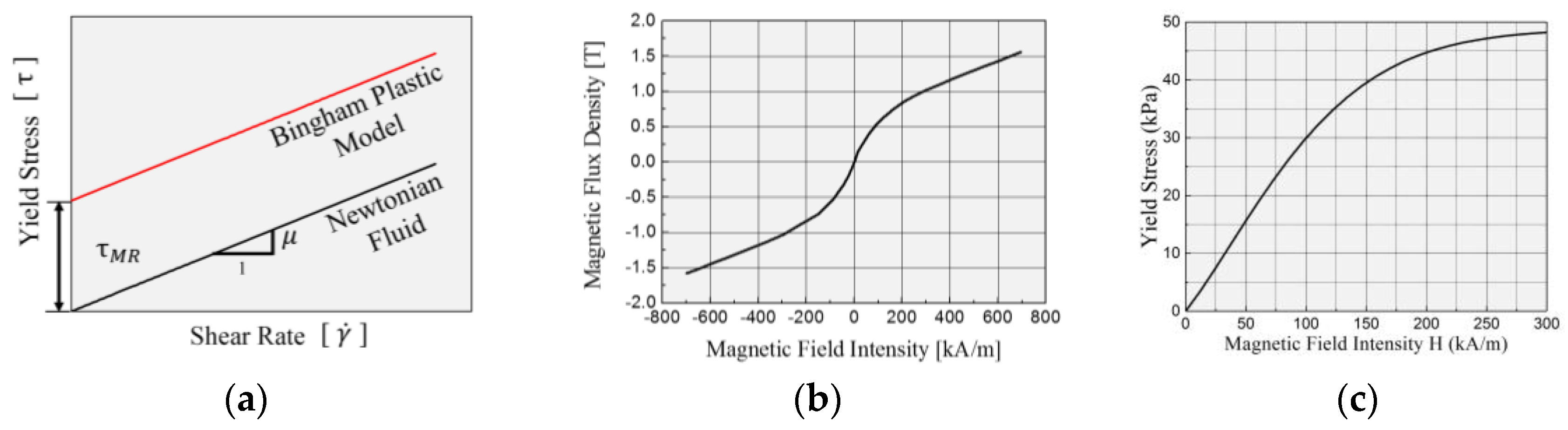
As is well known, MR fluid is a mixture of magnetizable particles, like iron, and non-magnetizable carrier fluid, such as silicone oil. When a magnetic field is applied on MR fluid, magnetized particles attract each other and form a chain along the magnetic flux line. Therefore, the chain structure increases the additional yield stress to be controlled by the magnetic intensity. In order to design an MR mount, the field-dependent yield stress of the MR fluid must first be identified. Figure 5a shows the inherent characteristics of MR fluid. The MR fluid has Newtonian characteristics without the magnetic field. This means that the yield shear stress of the fluid changes in proportion to the shear rate [15]. When the magnetic field is applied to the MR fluid, the properties of the MR fluid change from Newtonian to the Bingham plastic model, and its constitutive equation is given by
In the above, is the shear stress of MR fluid, is the viscosity, and is the shear rate of MR fluid. is the yield stress of MR fluid which is controllable by the magnitude of the external magnetic field. The is influenced by degree of magnetization and by the permeability. So, the relationship between magnetic flux density B and magnetic field intensity H needs to be established as shown in Figure 5b. In general, materials having higher permeability draw more magnetic flux lines and have larger magnetic field intensity. Figure 5c shows the relationship between the yield stress and magnetic field intensity H of MRF-132DG (Lord Corporation, Cary, NC, USA). In this study, –H relation was obtained by using the viscometer and polynomial equation from the data obtained as follows:
Figure 6a shows the schematic diagram of the proposed MR mount. In the design of the MR mount, design parameters were considered for interchangeable installation by commercial passive mounts without any modification. The dimension of the cabsus mount is standard with the design of the MR mount because the cabsus mount is bigger than the viscous mounts used currently. In order to maximize the damping force, a new type of duct, which is a combined annular duct and radial channel, was adopted in the mount, as shown in Figure 6b. The coil is wound in the center plate to control the MR fluid, and the magnetic flux line is generated as denoted by the red dotted lines in the figure. Thus, the field-dependent damping force is generated in both the annular duct and the radial channel.
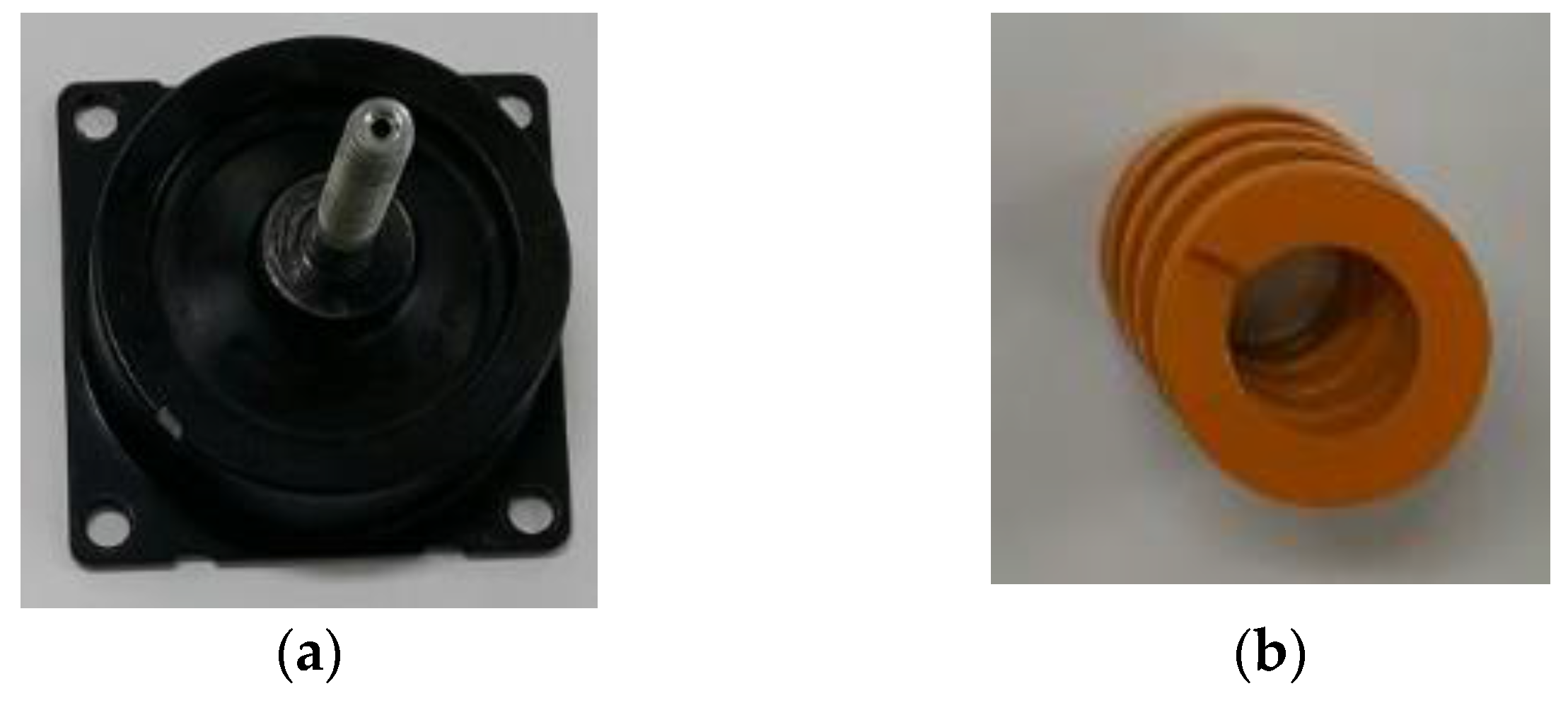
In this study, a rubber of low stiffness was utilized for isolation performance in the high frequency and the spring was used to support static load. Figure 7a shows the rubber part of the cabsus mount, and it was used for the design of MR mount. A rectangular (die) spring was used and connected with the rubber part for supporting the static load, as shown in the Figure 7b. Then, the total stiffness of the MR mount is expressed as follows:
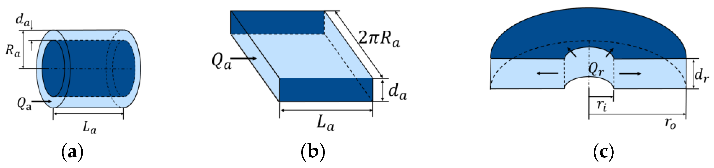
To design the damping force, the pressure drop should be calculated in the flow path. In this study, two types of pressure drops are derived and utilized for the design of the MR mount [16]. Figure 8a shows the annular duct having the thickness , length , radius and flow rate . So, the circumference of the duct could be assumed to be . Using a modified annular model with the assumption shown in Figure 8b, the pressure drop of the annular path is expressed as the sum of the viscous effect and MR effect as follows:
Secondly, the pressure drop of the radial flow path could be derived using the model shown in Figure 8c. The MR radial duct has the inner radius , outer radius , thickness and flow rate . Then, the pressure drop through the radial duct is derived as follows:
Now, using Equations (5) and (6), the total pressure drop along annular and radial paths is expressed as below:
Using symmetric dimensions in Figure 6b and knowing that , the total pressure drop is derived as follows:
In the above, and are the yield stress of the MR fluid in the annular and radial flow paths, respectively, which are functions of the magnetic field intensity at each flow path. Since the flow rate is the same as the volumetric transfer rate by the bobbin part for continuity, it is expressed as a multiple of the bobbin area and bobbin velocity of . Then, damping force is calculated using the following equation:
It is noted here that in the above equation, is included since the MR fluid only reacts to the movement of the bobbin part. On the other hand, the damping coefficient of the MR mount is achieved by considering the passive damping coefficient as follows [17]:
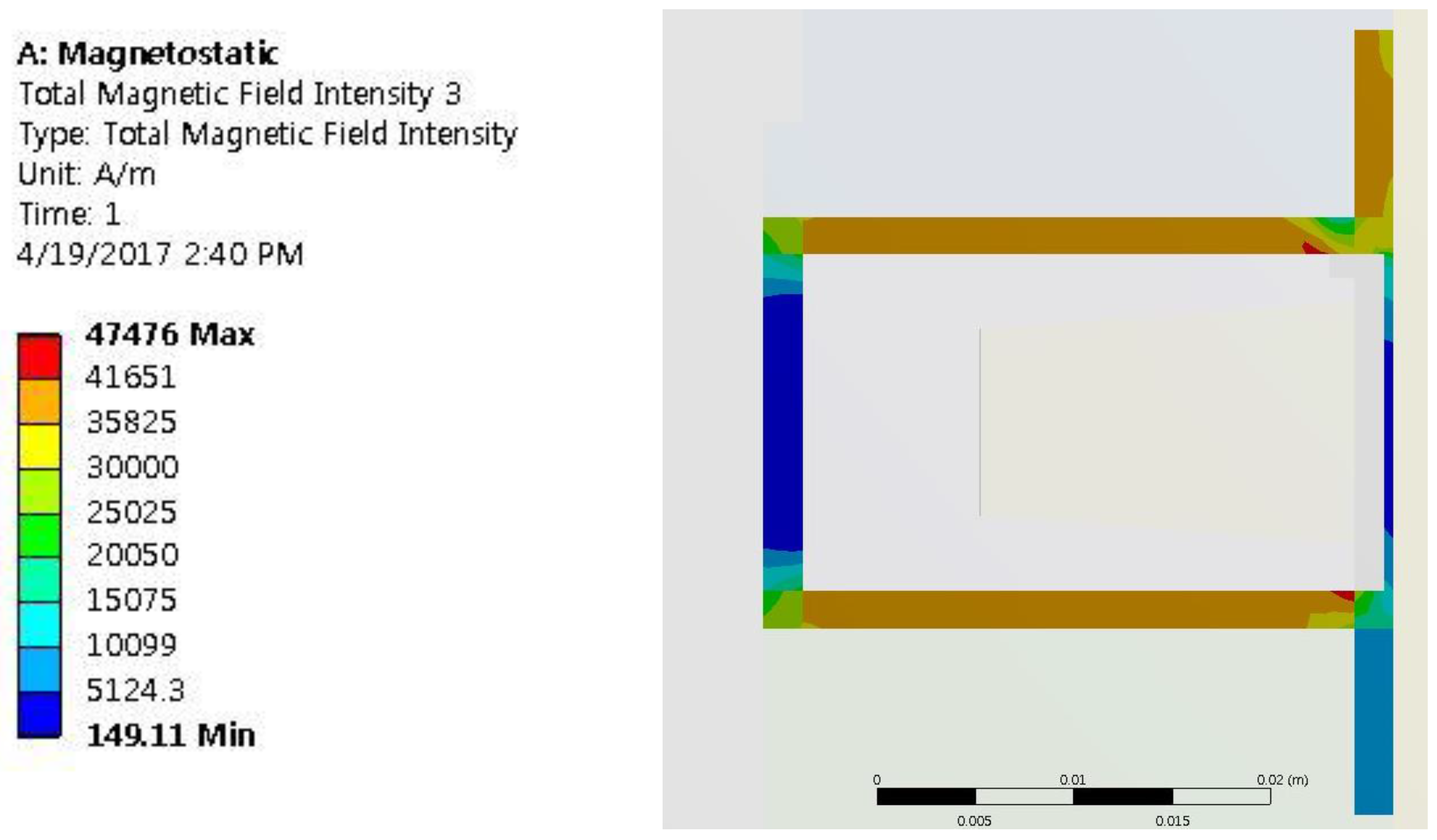
In the design of an MR mount, magnetic field analysis should be conducted to maximize the field-dependent damping force. In this work, optimization for the maximum damping force was undertaken with design parameters as shown in Figure 6b. To begin, t1 and t2, which are the annular and radial gap sizes, must be more than 2 mm because when they are less than 2 mm, the block phenomenon is easily observed. As shown in the Figure 6b, the coil has an isosceles trapezoid shape. The a, b, and c show height and bases length of bottom and upper side, respectively. The dimensions of the MR mount were optimized with the optimization tool in the ANSYS workbench as shown in Table 1. Figure 9 shows the computer simulation result of magnetic flux intensity using ANSYS software. The results show that the radial duct has uniform flux intensity, and the nearest coil has highest intensity. However, the two annular ducts have different results because the mount does not have a symmetric structure.
After optimization, the magnitude of the generated force by the MR fluid can be calculated using Equations (3) and (9) with the properties of the field-dependent yield stress. Figure 10 shows the photographs of the manufactured MR mount. As designed in Figure 6a and Table 1, the combination of rubber and spring generate the total spring forces, and the bobbin parts generate the damping force from the MR fluid flow paths with housing. A two-end type mount structure was adopted for simple design of the damping part since it does not need a volume compensator. For experimental convenience, the bobbin and spring part was separated by the housing part to easily change stiffness without disassembling the bobbin part. An O-ring was inserted between each housing part and oil seal was installed at the inner center between upper and lower housings to prevent leakage.
4. Experimental Results and Discussion
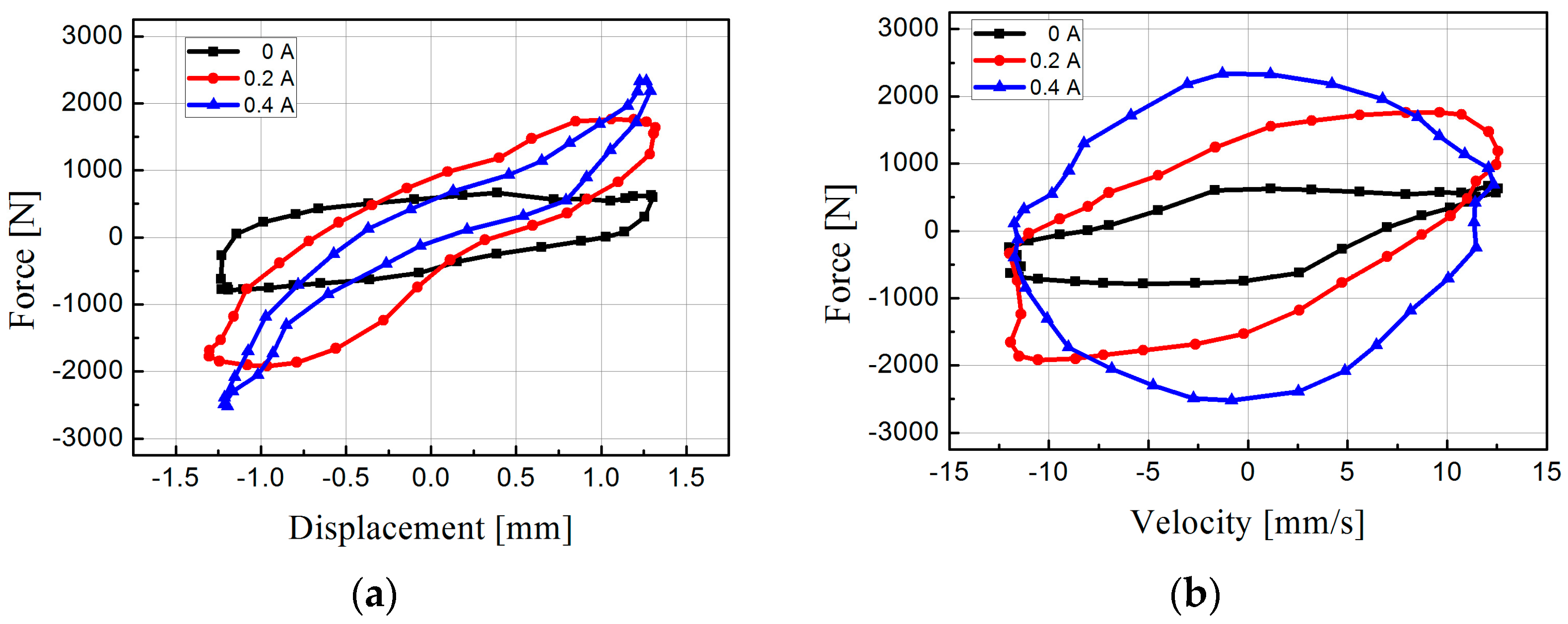
The performance of the proposed MR mount was evaluated by the experimental apparatus. All signals were simultaneously obtained and saved by the computer during the experimental test. Figure 11 shows the experimental results of a force-displacement diagram and a force-velocity diagram. The mount was excited with the magnitude of 1.4 mm and a frequency of 2 Hz of sinusoidal excitation. As shown in the Figure 11, the MR mount had 780 N of the maximum damping force when the input current was not applied (0 A). It was expected that the proposed MR mount have properties and transmissibility similar to that of the cabsus mount with zero current. Furthermore, the damping force was increased as the input current increased. The maximum damping force is 2200 N with 0.4 A and the block-up phenomenon was observed when 0.4 A was applied. However, the graph of force-displacement is not very different than that of the viscous mount. It was also expected that the transmissibility of the MR mount would be similar to the Viscous mount with 0.4 A. From the results, the proposed MR mount can control damping forces from 780 to 2200 N with 2 Hz and 1.4 mm of excitation frequency and amplitude, respectively.
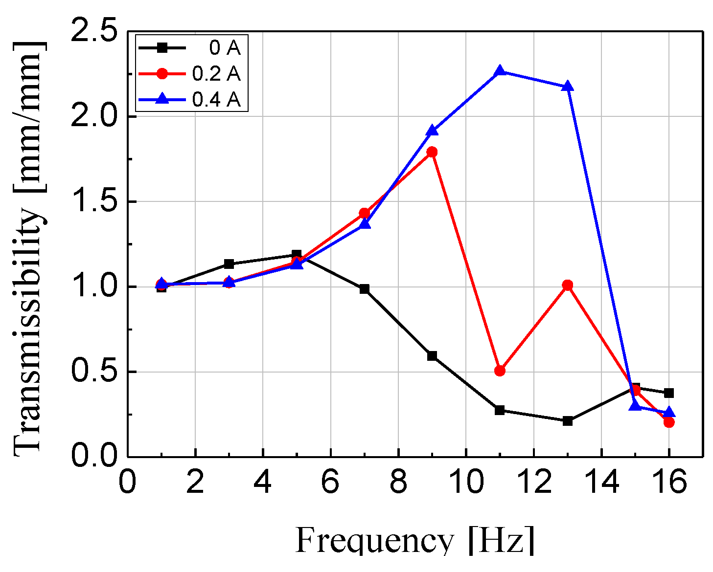
Figure 12 shows transmissibility of the manufactured MR mount with constant current from 0 A to 0.4 A with 0.2 A intervals. As shown in the results, the transmissibility was higher than the viscous mount under 5 Hz excitation frequencies. However, the MR mount has lower transmissibility over 5 Hz when current is not applied. When 0.4 A is applied, the MR mount has the highest transmissibility over 5 Hz, but the transmissibility is lower than for the cabsus mount. This means that the MR mount shows lower transmissibility in various frequency ranges.
Figure 13 shows the transmissibility results of the MR mount with control logic compared with that of two passive rubber mounts. A simple on-off control algorithm was used for control of the MR mount. The input frequency was analyzed by fast Fourier transform (FFT), and the controller could turn on or off the current driver. The control currents were chosen to be zero or 0.4 A. When the excitation frequency was under 5 Hz, the 0.4 A of the control input was applied, and the current driver was turned off over 5 Hz. As shown in Figure 12, the controlled MR mount provides excellent performance for vibration control within the whole frequency range. The proposed MR mount has better performance than the cabsus mount within the whole frequency range. The viscous mount has slightly better performance under 5 Hz. However, the MR mount has higher performance over 5 Hz. Therefore, the proposed MR mount can provide better performance than the passive mount. The adaptive optimal controller will be designed for the MR mount and the mount will be installed and tested in real wheel loader cabin system.
5. Conclusions
In this study, a semi-active MR mount has been proposed and evaluated to resolve the vibration problem of heavy vehicles. First of all, two types of experimental apparatuses were designed for performance evaluation of damping force and transmissibility. Then, the dynamic characteristics of two different passive mounts were investigated to properly design the MR mount. The maximum damping force of the cabsus and viscous mounts were 750 and 2200 N, respectively, with 2 Hz of excitation frequency and 1.4 mm amplitude. The stiffness of the MR mount was designed by using the rubber part and a rectangular spring, while the damping coefficient was determined by the pressure drop through the flow paths in the bobbin. In addition, analysis of the magnetic field intensity was executed to optimize the MR effect. Subsequently, the performance evaluation of the MR damper was undertaken with the same frequency and amplitude as those of the passive rubber mounts. The minimum and maximum damping force were identified as 780 N and 2200 N, respectively. It has been demonstrated that the proposed MR mount has two different characteristic patterns: cabsus rubber mount characteristics without the input current and viscous rubber mount characteristics with the maximum input current. As for the controller, a simple but very effective on-off controller was used for damping force control and was associated with the FFT algorithm which had the switching frequency of 5 Hz.
The results are self-explanatory and justify that a controllable semi-active MR mount can be usefully applied in a large frequency range to attenuate severe vibrations of heavy equipment vehicles such as wheel loaders. In future research, an optimal controller will be designed for the various excitation conditions and the MR mount will be installed and tested with a real heavy vehicle system such as a wheel loader cabin system.
Author Contributions
S.B. Choi and S.Y. Yang conceived and designed the experiments; C. Han performed the experiments; S.U. Shin analyzed the data; S.U. Shin contributed reagents/materials/analysis tools; S. B. Choi, S.Y. Yang and C. Han wrote the paper.
Conflicts of Interest
The authors declare no conflict of interest.
Nomenclature
| Effective Area of Bobbin Part | |
| Damping Coefficient of Suspension | |
| Compliance of Annular Duct | |
| Compliance of Radial Duct | |
| Thickness of Annular Duct | |
| Thickness of Radial Duct | |
| Magnetic Field Intensity at MR Fluid | |
| Applied Current in Coil | |
| Stiffness of Suspension | |
| Stiffness of Rubber Part | |
| Stiffness of Spring Part | |
| Total Stiffness of the Designed MR Mount | |
| Quarter Mass of Cabin | |
| Viscosity of MR Fluid | |
| Pressure Drop at Annular Duct | |
| Pressure Drop at Radial Duct | |
| Total Pressure Drop through MR Fluid Paths | |
| Pressure Drop by Viscous Effect | |
| Pressure Drop by MR Fluid Effect | |
| Flow Rate at Annular Duct | |
| Flow Rate at Radial Duct | |
| Radius of Annular Duct from Center | |
| Inner Radius of Radial Duct | |
| Outer Radius of Radial Duct | |
| Relative Bobbin Velocity between Mass and Base | |
| Excitation Frequency | |
| Natural Frequency | |
| Displacement of Mass | |
| Amplitude of Mass | |
| Displacement of Base | |
| Amplitude of Base | |
| Yield Stress of MR Fluid Effect | |
| Total Yield Stress of MR Fluid | |
| Yield Stress of MR Fluid Effect at Annular Duct | |
| Yield Stress of MR Fluid Effect at Radial Duct | |
| Damping Ratio | |
| Shear Rate of MR Fluid |
References
- Bovenzi, M. Health effects of mechanical vibration. G. Ital. Med. Lav. Ergon. 2005, 27, 58–64. [Google Scholar] [PubMed]
- ISO. Mechanical Vibration and Shock: Evaluation of Human Exposure to Whole-body Vibration. Part 1. In General Requirements: International Standard ISO 2631-1; ISO: Geneva, Switzerland, 1997. [Google Scholar]
- British Standards Institution. British Standard Guide to Measurement and Evaluation of Human Exposure to Whole-Body Mechanical Vibration and Repeated Shock; British Standards Institution: London, UK, 1987. [Google Scholar]
- Kim, G.; Singh, R. Nonlinear analysis of automotive hydraulic engine mount. J. Dyn. Syst. Meas. Control 1993, 115, 482–487. [Google Scholar] [CrossRef]
- Flower, W.C. Understanding Hydraulic Mounts for Improved Vehicle Noise, Vibration and Ride Qualities; SAE: Warrendale, PA, USA, 1985. [Google Scholar]
- Shibayama, T.; Ito, K.; Gami, T.; Oku, T.; Nakajima, Z.; Ichikawa, A. Active Engine Mount for a Large Amplitude of Idling Vibration; SAE: Warrendale, PA, USA, 1995. [Google Scholar]
- Togashi, C.; Ken, I. Study on Hydraulic Active Engine Mount; SAE: Warrendale, PA, USA, 2003. [Google Scholar]
- Deprez, K.; Moshou, D.; Anthonis, J.; De Baerdemaeker, J.; Ramon, H. Improvement of vibrational comfort on agricultural vehicles by passive and semi-active cabin suspensions. Comput. Electron. Agric. 2005, 49, 431–440. [Google Scholar] [CrossRef]
- Choi, S.B.; Park, D.W.; Lee, D.Y. Optimal control of an electrorheological fluid suspension system for tracked vehicles. Proc. Inst. Mech. Eng. Part D 2005, 219, 843–855. [Google Scholar] [CrossRef]
- Kim, H.C.; Choi, S.B.; Lee, G.S.; An, C.H.; You, W.H. Performance analysis of a semi-active railway vehicle suspension featuring MR dampers. In Proceedings of the SPIE Smart Structures and Materials and Nondestructive Evaluation and Health Monitoring, International Society for Optics and Photonics, San Diego, CA, USA, 9 March 2014. [Google Scholar]
- Brigley, M.; Choi, Y.T.; Wereley, N.M.; Choi, S.B. Magnetorheological isolators using multiple fluid modes. J. Intell. Mater. Syst. Struct. 2007, 18, 1143–1148. [Google Scholar] [CrossRef]
- York, D.; Wang, X.; Gordaninejad, F. A new magnetorheological mount for vibration control. J. Vib. Acoust. 2011, 133, 031003. [Google Scholar] [CrossRef]
- Kang, O.H.; Kim, W.H.; Joo, W.H.; Park, J.H. Design of the magnetorheological mount with high damping force for medium speed diesel generators. Act. Passiv. Smart Struct. Integr. Syst. 2013, 8688. [Google Scholar] [CrossRef]
- Phu, D.X.; Hung, N.Q.; Park, J.H.; Choi, S.B. Design of a new MR brake mount system considering vertical and horizontal vibrations. Proc. SPIE 2014, 9057. [Google Scholar] [CrossRef]
- De, V.J.; Klingenberg, D.J.; Hidalgo, A.R. Magnetorheological fluids: A review. Soft Matter 2011, 7, 3701–3710. [Google Scholar]
- Ai, H.X.; Wang, D.H.; Liao, W.H. Design and modeling of a magnetorheological valve with both annular and radial flow paths. J. Intell. Mater. Syst. Struct. 2006, 17, 327–334. [Google Scholar] [CrossRef]
- Nguyen, Q.H.; Phu, D.X.; Park, J.H.; Choi, S.B.; Kang, O.H. Development of high damping magneto-rheological mount for ship engines. Appl. Mech. Mater. 2013, 336, 953–959. [Google Scholar] [CrossRef]
Figure 1.
Commercialized passive rubber mounts for cabin.

Figure 2.
Experimental apparatus for damping force measurement. DAQ = data acquisition; RVDT = rotary variable differential transformer; LVDT = linear variable differential transformer.
Figure 2.
Experimental apparatus for damping force measurement. DAQ = data acquisition; RVDT = rotary variable differential transformer; LVDT = linear variable differential transformer.
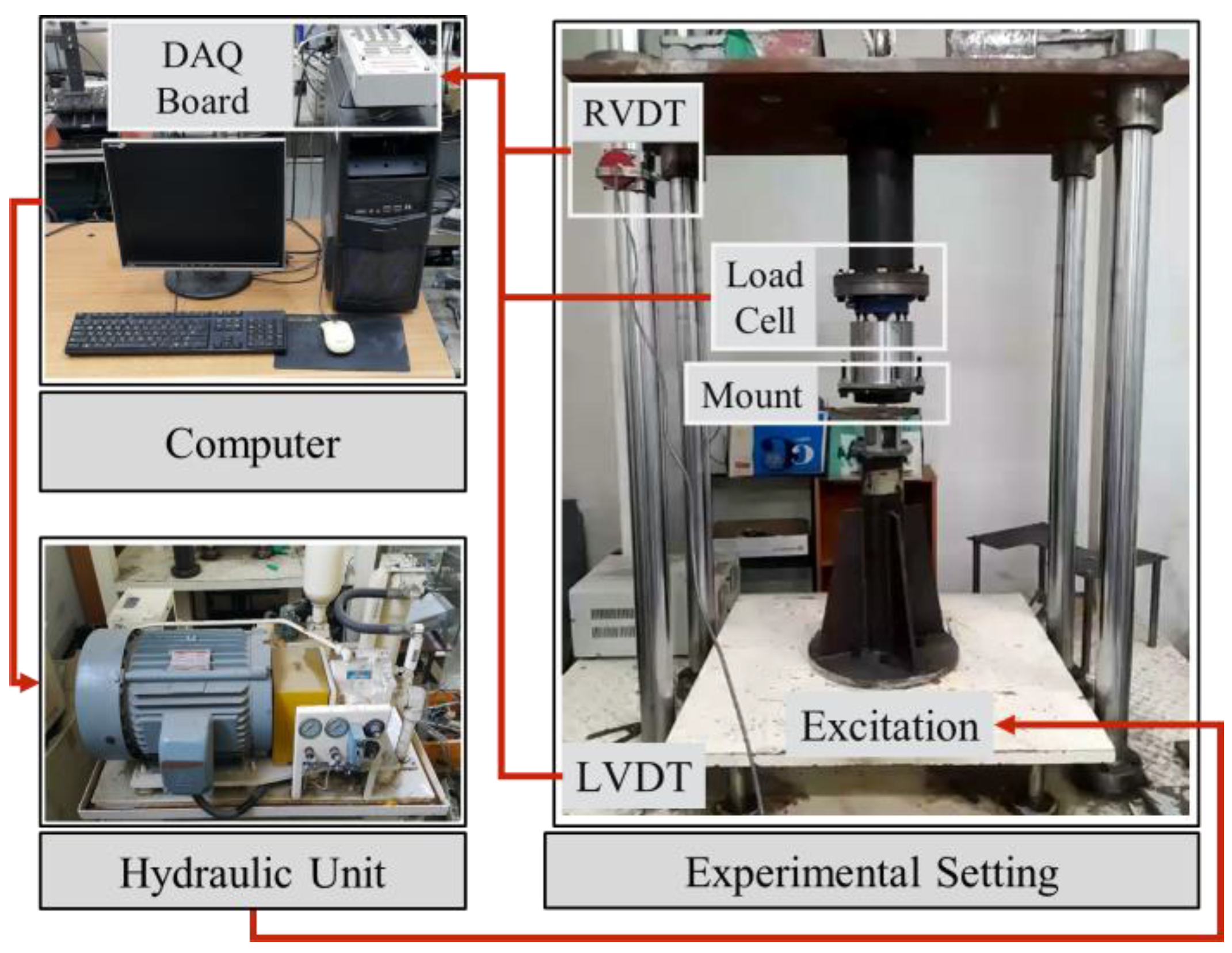
Figure 3.
Dynamic characteristics of passive mounts: (a) force-displacement diagram; (b) force-velocity diagram.
Figure 3.
Dynamic characteristics of passive mounts: (a) force-displacement diagram; (b) force-velocity diagram.

Figure 4.
Transmissibility of passive rubber mounts.

Figure 5.
Properties of magneto-rheological (MR) fluid: (a) general properties of MR fluid; (b) B-H curve; (c) -H curve.
Figure 5.
Properties of magneto-rheological (MR) fluid: (a) general properties of MR fluid; (b) B-H curve; (c) -H curve.

Figure 6.
Modeling of MR mount: (a) schematic structure; (b) design parameters and flow path.
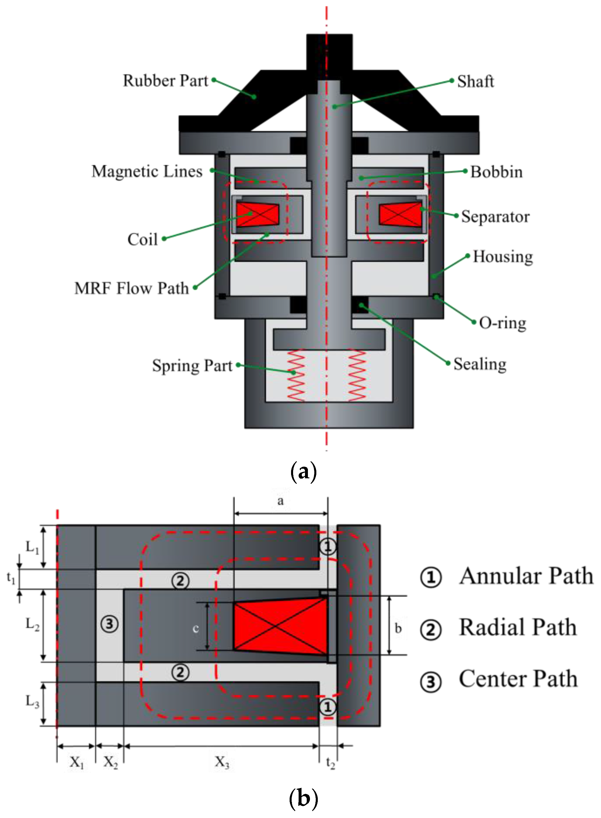
Figure 7.
Photograph of stiffness parts: (a) rubber part; (b) spring part.

Figure 8.
Components of the fluid flow path: (a) annular path; (b) modified annular path; (c) radial path.
Figure 8.
Components of the fluid flow path: (a) annular path; (b) modified annular path; (c) radial path.

Figure 9.
Simulation result of magnetic flux intensity.

Figure 10.
Photograph of the MR mount: (a) parts; (b) assembled.
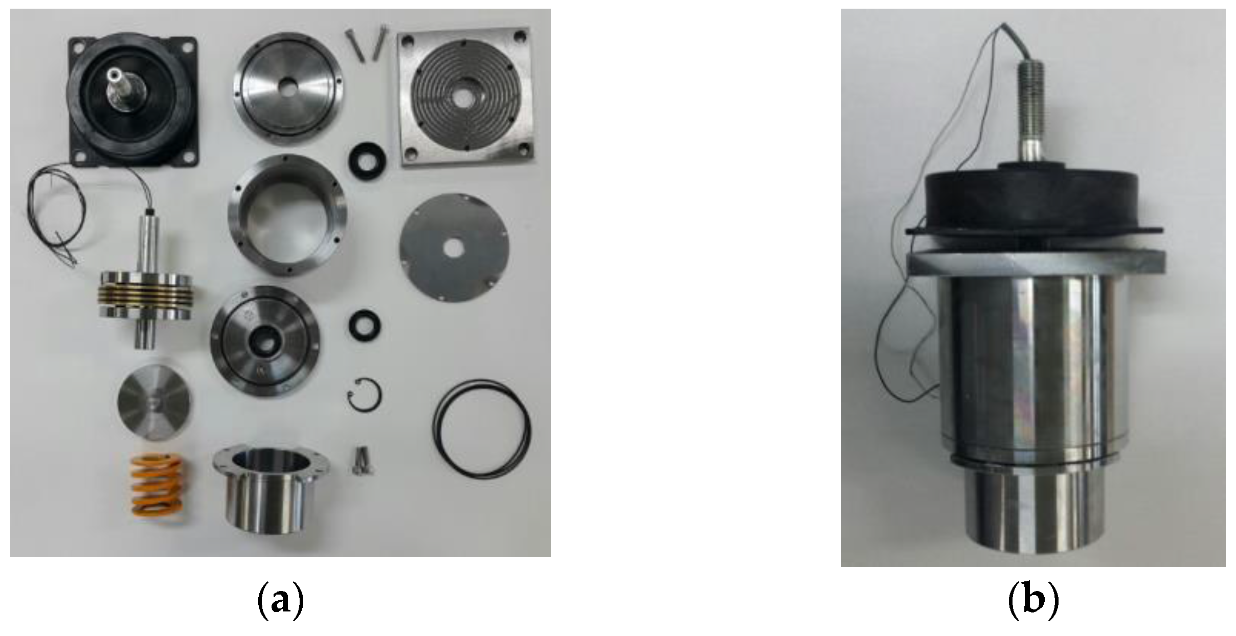
Figure 11.
Properties of the proposed MR mounts: (a) force-displacement diagram; (b) force-velocity diagram.
Figure 11.
Properties of the proposed MR mounts: (a) force-displacement diagram; (b) force-velocity diagram.

Figure 12.
Transmissibility diagram of the MR mounts.

Figure 13.
Comparison of the passive rubber mount and the MR mount.


Table 1.
Dimensions of the MR mount.
| Name | Dimensions (mm) | Name | Dimensions (mm) |
|---|---|---|---|
| 10 | 2 | ||
| 18 | 2 | ||
| 10 | a | 19 | |
| 8 | b | 14 | |
| 2 | c | 12 | |
| 33.5 |
© 2017 by the authors. Licensee MDPI, Basel, Switzerland. This article is an open access article distributed under the terms and conditions of the Creative Commons Attribution (CC BY) license (http://creativecommons.org/licenses/by/4.0/).
Share and Cite
MDPI and ACS Style
Yang, S.-Y.; Han, C.; Shin, S.-U.; Choi, S.-B. Design and Evaluation of a Semi-Active Magneto-rheological Mount for a Wheel Loader Cabin. Actuators 2017, 6, 16. https://doi.org/10.3390/act6020016
AMA Style
Yang S-Y, Han C, Shin S-U, Choi S-B. Design and Evaluation of a Semi-Active Magneto-rheological Mount for a Wheel Loader Cabin. Actuators. 2017; 6(2):16. https://doi.org/10.3390/act6020016
Chicago/Turabian StyleYang, Soon-Yong, Chulhee Han, Sang-Un Shin, and Seung-Bok Choi. 2017. "Design and Evaluation of a Semi-Active Magneto-rheological Mount for a Wheel Loader Cabin" Actuators 6, no. 2: 16. https://doi.org/10.3390/act6020016
Note that from the first issue of 2016, this journal uses article numbers instead of page numbers. See further details here.