
Re-Engineering a High Performance Electrical Series Elastic Actuator for Low-Cost Industrial Applications

Abstract
:1. Introduction
2. Design
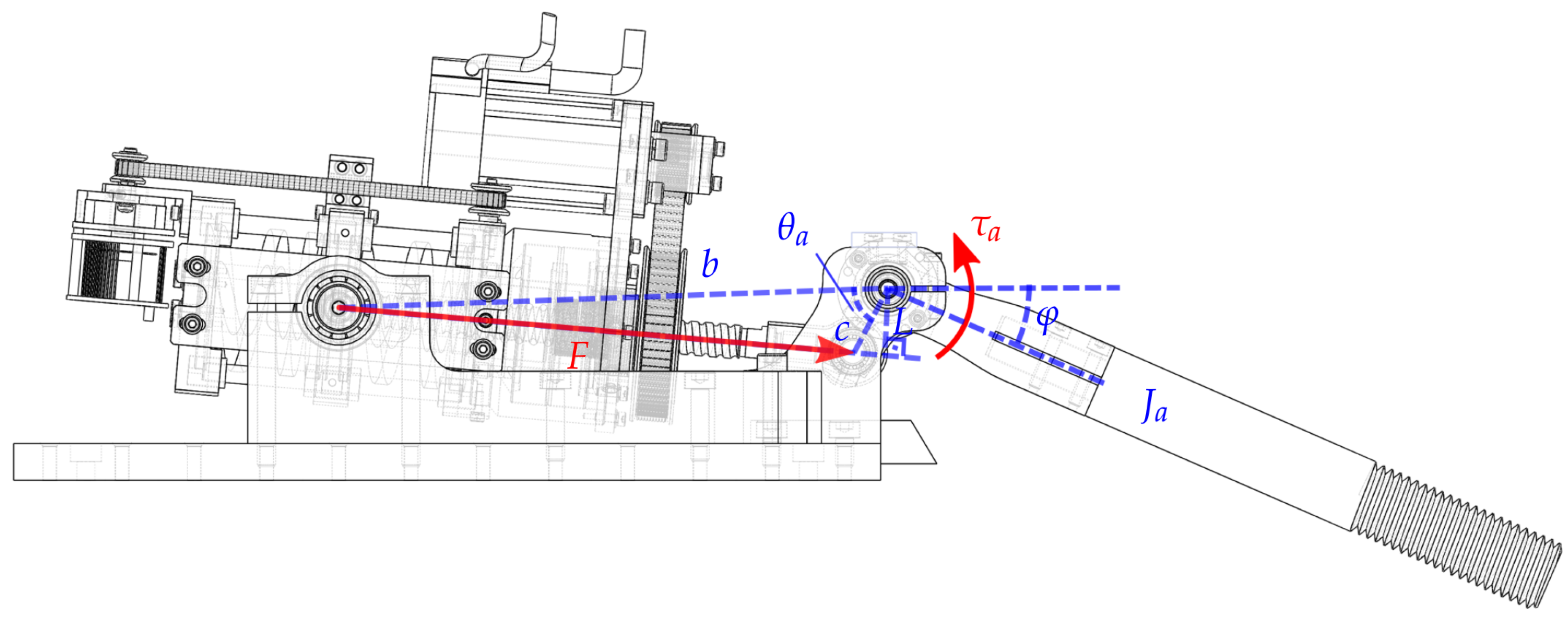
3. Modeling and Control
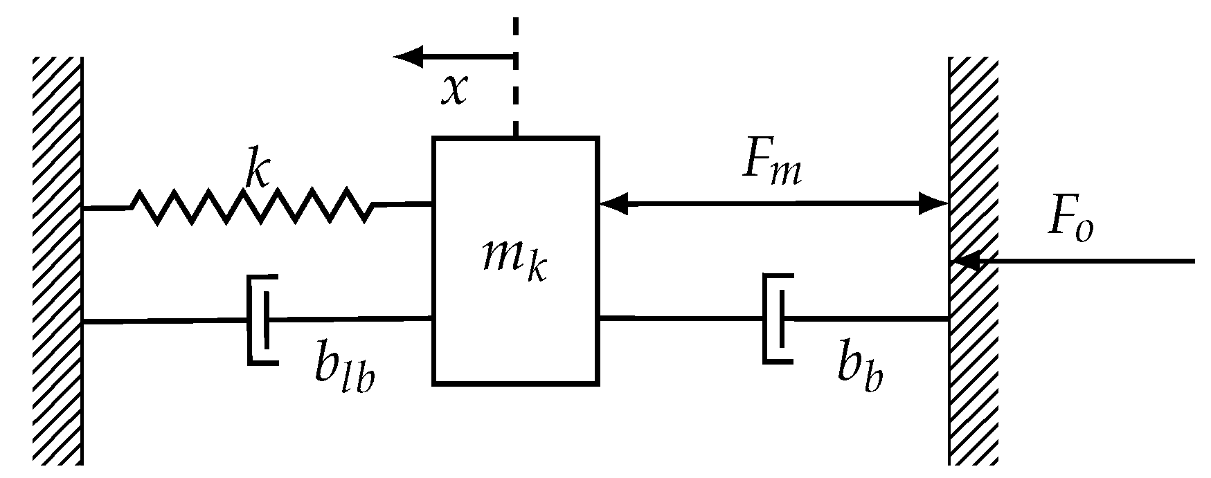
3.1. Modeling
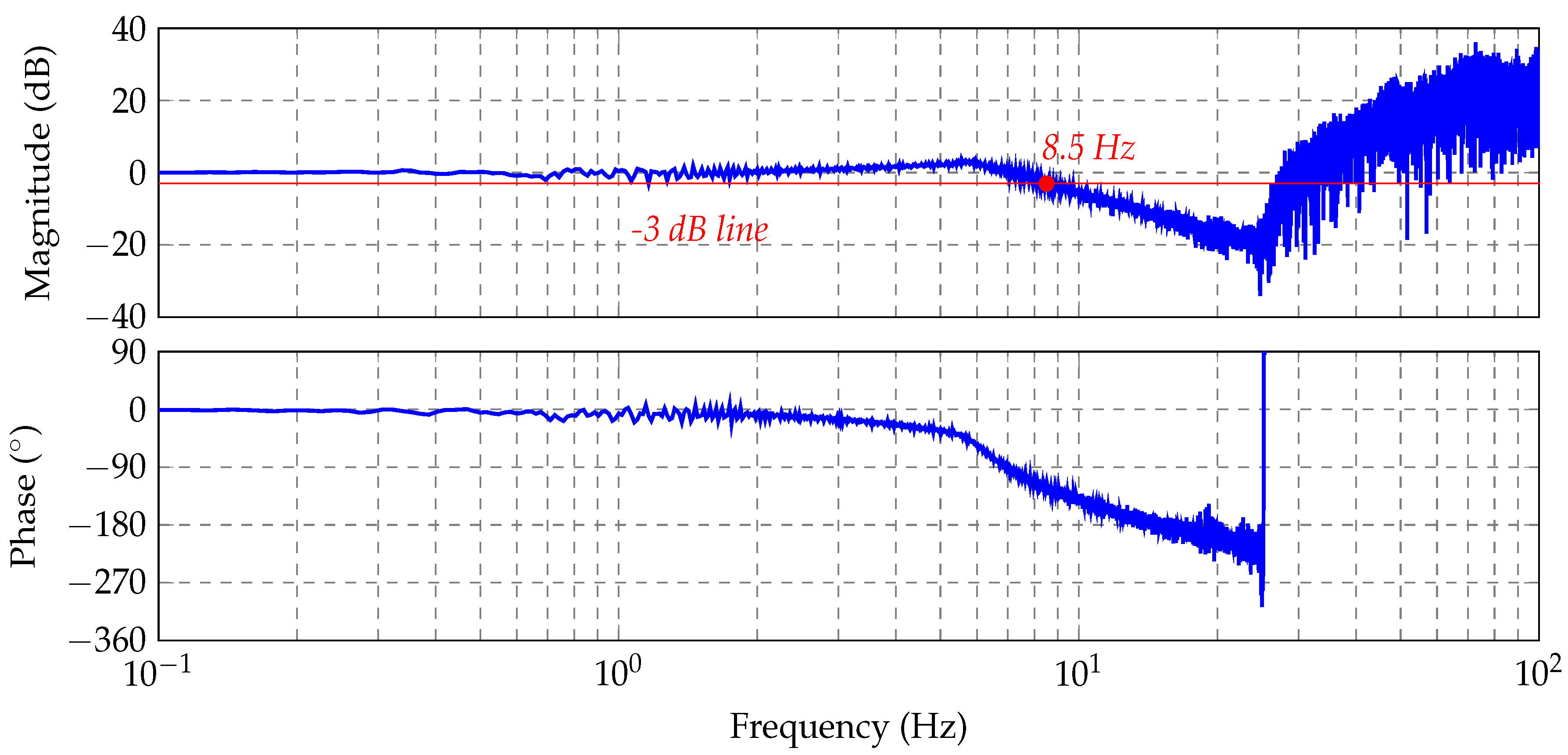
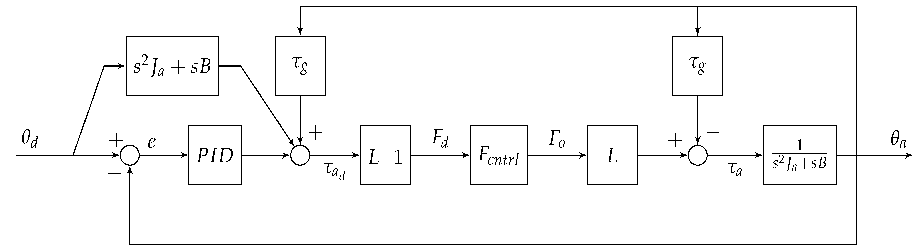
3.2. Force Control
3.3. Position Control
4. Performance Tests
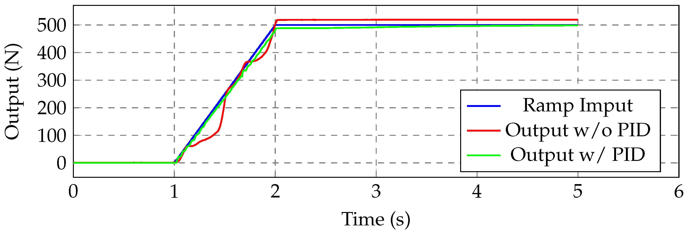
4.1. Force Control Test
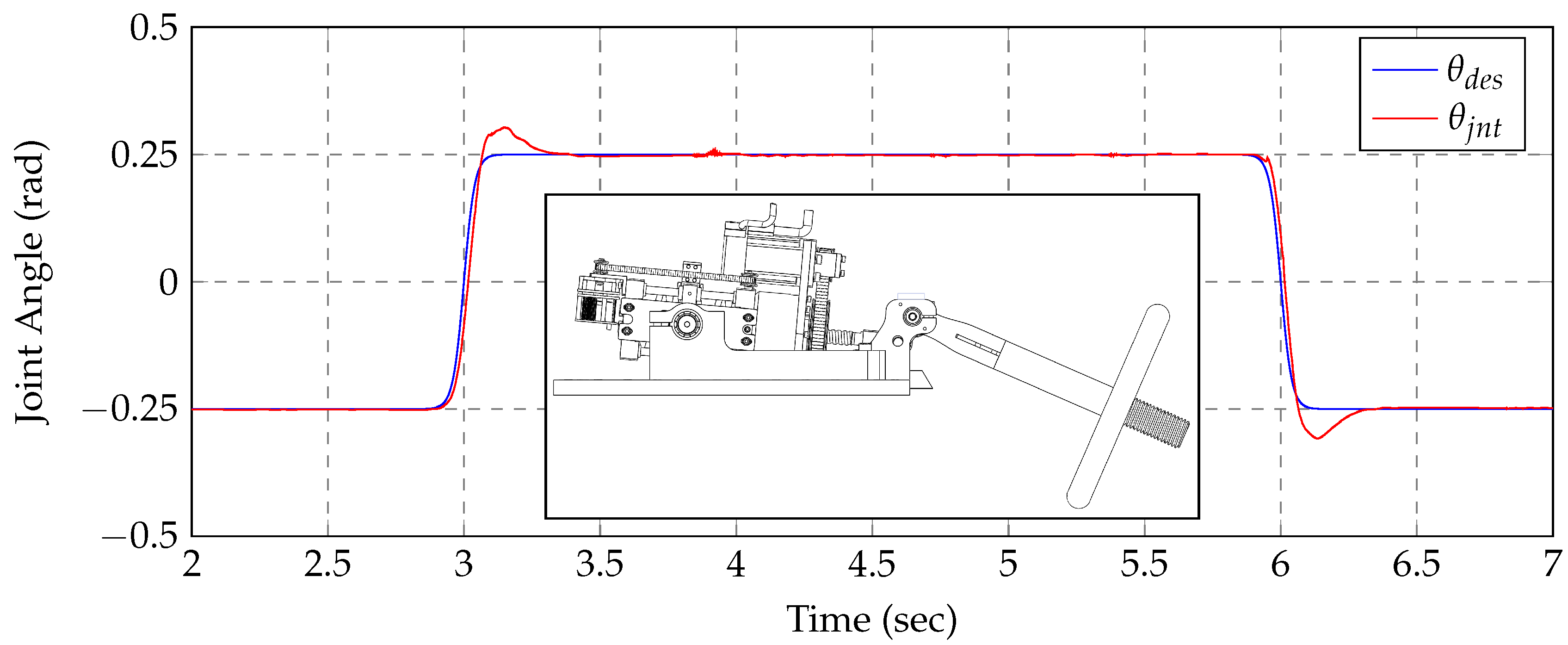
4.2. Position Control Test
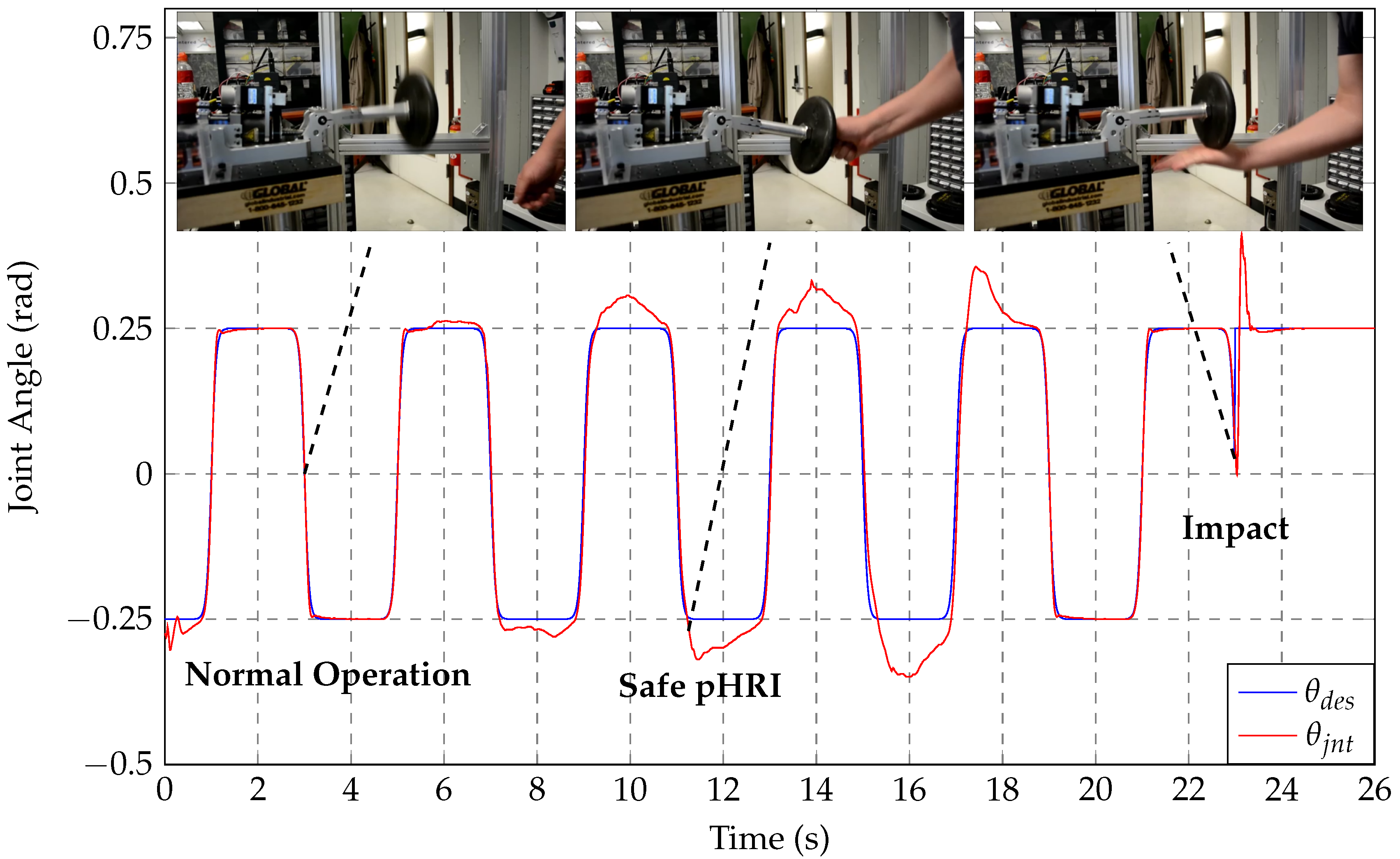
4.3. Impact Detection Test
5. Conclusions
Acknowledgments
Author Contributions
Conflicts of Interest
References
- Pratt, G.A.; Williamson, M.M. Series Elastic Actuators. In Proceedings of the IEEE/RSJ International Conference on Intelligent Robots and Systems. Human Robot Interaction and Cooperative Robots, Pittsburgh, PA, USA, 5–9 August 1995; Volume 1, pp. 399–406.
- Arumugom, S.; Muthuraman, S.; Ponselvan, V. Modeling and Application of Series Elastic Actuators for Force Control Multi Legged Robots. J. Comput. 2009, 1, 26–33. [Google Scholar]
- Paluska, D.; Herr, H. Series Elasticity and Actuator Power Output. In Proceedings of the IEEE International Conference on Robotics and Automation, Orlando, FL, USA, 15–19 May 2006; pp. 1830–1833.
- Lagoda, C.; Schou, A.C.; Stienen, A.H.; Hekman, E.E.; van der Kooij, H. Design of an Electric Series Elastic Actuated Joint for Robotic Gait Rehabilitation Training. In Proceedings of the 3rd IEEE RAS and EMBS International Conference on Biomedical Robotics and Biomechatronics (BioRob), Tokyo, Japan, 26–29 September 2010; pp. 21–26.
- Diftler, M.A.; Mehling, J.; Abdallah, M.E.; Radford, N.A.; Bridgwater, L.B.; Sanders, A.M.; Askew, R.S.; Linn, D.M.; Yamokoski, J.D.; Permenter, F.; et al. Robonaut 2—The First Humanoid Robot in Space. In Proceedings of the IEEE International Conference on Robotics and Automation (ICRA), Shanghai, China, 9–13 May 2011; pp. 2178–2183.
- Sergi, F.; Accoto, D.; Carpino, G.; Tagliamonte, N.L.; Guglielmelli, E. Design and Characterization of a Compact Rotary Series Elastic Actuator for Knee Assistance during Overground Walking. In Proceedings of the 4th IEEE RAS & EMBS International Conference on Biomedical Robotics and Biomechatronics (BioRob), Rome, Italy, 24–27 June 2012; pp. 1931–1936.
- Lu, J.; Haninger, K.; Chen, W.; Tomizuka, M. Design and Torque-Mode Control of a Cable-Driven Rotary Series Elastic Actuator for Subject-Robot Interaction. In Proceedings of the IEEE International Conference on Advanced Intelligent Mechatronics (AIM), Banff, AB, Canada, 12–15 July 2015; pp. 158–164.
- Veneman, J.F.; Ekkelenkamp, R.; Kruidhof, R.; van der Helm, F.C.; van der Kooij, H. A Series Elastic- and Bowden-Cable-Based Actuation System for Use as Torque Actuator in Exoskeleton-Type Robots. Int. J. Rob. Res. 2006, 25, 261–281. [Google Scholar] [CrossRef]
- Torres-Jara, E.; Banks, J. A Simple and Scalable Force Actuator; Technical Report, DTIC Document; Defense Technical Information Center: Fort Belvoir, VA, USA, 2005. [Google Scholar]
- Sensinger, J.W.; Burkart, L.E.; Pratt, G.A.; Weir, R.F. Effect of Compliance Location in Series Elastic Actuators. Robotica 2013, 31, 1313–1318. [Google Scholar] [CrossRef]
- Kong, K.; Bae, J.; Tomizuka, M. A Compact Rotary Series Elastic Actuator for Human Assistive Systems. IEEE/ASME Trans. Mechatron. 2012, 17, 288–297. [Google Scholar] [CrossRef]
- Taylor, M.D. A Compact Series Elastic Actuator for Bipedal Robots with Human-Like Dynamic Performance. Ph.D. Thesis, Carnegie Mellon University, Pittsburgh, PA, USA, 2011. [Google Scholar]
- Mathijssen, G.; Cherelle, P.; Lefeber, D.; Vanderborght, B. Concept of a Series-Parallel Elastic Actuator for a Powered Transtibial Prosthesis. Actuators 2013, 2, 59–73. [Google Scholar] [CrossRef]
- Dos Santos, W.M.; Caurin, G.A.; Siqueira, A.A. Design and control of an active knee orthosis driven by a rotary Series Elastic Actuator. Control Eng. Pract. 2015. [Google Scholar] [CrossRef]
- Tsagarakis, N.G.; Laffranchi, M.; Vanderborght, B.; Caldwell, D.G. A Compact Soft Actuator Unit for Small Scale Human Friendly Robots. In Proceedings of the IEEE International Conference on Robotics and Automation, Kobe, Japan, 12–17 May 2009; pp. 4356–4362.
- Hurst, J.W.; Chestnutt, J.E.; Rizzi, A. The actuator with mechanically adjustable series compliance. IEEE Trans. Robot. 2010, 26, 597–606. [Google Scholar] [CrossRef]
- Grebenstein, M.; Albu-Schäffer, A.; Bahls, T.; Chalon, M.; Eiberger, O.; Friedl, W.; Gruber, R.; Haddadin, S.; Hagn, U.; Haslinger, R.; et al. The DLR Hand Arm System. In Proceedings of the IEEE International Conference on Robotics and Automation (ICRA), Shanghai, China, 9–13 May 2011; pp. 3175–3182.
- Jafari, A.; Tsagarakis, N.G.; Caldwell, D.G. A novel intrinsically energy efficient actuator with adjustable stiffness (AwAS). IEEE ASME Trans. Mechatron. 2013, 18, 355–365. [Google Scholar] [CrossRef]
- Tonietti, G.; Schiavi, R.; Bicchi, A. Design and Control of a Variable Stiffness Actuator for Safe and Fast Physical Human/Robot Interaction. In Proceedings of the IEEE International Conference on Robotics and Automation, Barcelona, Spain, 18–22 April 2005; pp. 526–531.
- Van Ham, R.; Vanderborght, B.; Van Damme, M.; Verrelst, B.; Lefeber, D. MACCEPA, the mechanically adjustable compliance and controllable equilibrium position actuator: Design and implementation in a biped robot. Rob. Auton. Syst. 2007, 55, 761–768. [Google Scholar] [CrossRef]
- Wolf, S.; Hirzinger, G. A New Variable Stiffness Design: Matching Requirements of the Next Robot Generation. In Proceedings of the IEEE International Conference on Robotics and Automation, Pasadena, CA, USA, 19–23 May 2008; pp. 1741–1746.
- Thorson, I.; Caldwell, D. A Nonlinear Series Elastic Actuator for Highly Dynamic Motions. In Proceedings of the IEEE/RSJ International Conference on Intelligent Robots and Systems (IROS), San Francisco, CA, USA, 25–30 September 2011; pp. 390–394.
- Groothuis, S.; Carloni, R.; Stramigioli, S. A Novel Variable Stiffness Mechanism Capable of an Infinite Stiffness Range and Unlimited Decoupled Output Motion. Actuators 2014, 3, 107–123. [Google Scholar] [CrossRef]
- Laffranchi, M.; Chen, L.; Kashiri, N.; Lee, J.; Tsagarakis, N.G.; Caldwell, D.G. Development and Control of a Series Elastic Actuator Equipped with a Semi Active Friction Damper for Human Friendly Robots. Rob. Auton. Syst. 2014, 62, 1827–1836. [Google Scholar] [CrossRef]
- Mooney, L.; Herr, H. Continuously-Variable Series-Elastic Actuator. In Proceedings of the IEEE International Conference on Rehabilitation Robotics (ICORR), Seattle, WA, USA, 24–26 June 2013; pp. 1–6.
- Paine, N.; Oh, S.; Sentis, L. Design and Control Considerations for High-Performance Series Elastic Actuators. IEEE/ASME Trans. Mechatron. 2014, 19, 1080–1091. [Google Scholar] [CrossRef]
- Edsinger-Gonzales, A.; Weber, J. Domo: A Force Sensing Humanoid Robot for Manipulation Research. In Proceedings of the 4th IEEE/RAS International Conference on Humanoid Robots, Santa Monica, CA, USA, 10–12 November 2004; Volume 1, pp. 273–291.
- Gregorio, P.; Ahmadi, M.; Buehler, M. Design, Control, and Energetics of An Electrically Actuated Legged Robot. IEEE Trans. Syst. Man Cybern. B Cybern. 1997, 27, 626–634. [Google Scholar] [CrossRef] [PubMed]
- Pratt, J.; Pratt, G. Intuitive Control of a Planar Bipedal Walking Robot. In Proceedings of the IEEE International Conference on Robotics and Automation, Leuven, Belgium, 16–20 May 1998; Volume 3, pp. 2014–2021.
- Pratt, J.E.; Krupp, B.T. Series Elastic Actuators for Legged Robots. Defense and Security. ternational Society for Optics and Photonics; SPIE: Bellingham, WA, USA, 2004; pp. 135–144. [Google Scholar]
- Hutter, M.; Remy, C.D.; Siegwart, R. Design of an Articulated Robotic Leg with Nonlinear Series Elastic Actuation; World Scientific: Singapore, 2009. [Google Scholar]
- Kong, K.; Bae, J.; Tomizuka, M. Control of Rotary Series Elastic Actuator for Ideal Force-Mode Actuation in Human–Robot Interaction Applications. IEEE ASME Trans. Mechatron. 2009, 14, 105–118. [Google Scholar] [CrossRef]
- Ragonesi, D.; Agrawal, S.; Sample, W.; Rahman, T. Series Elastic Actuator Control of a Powered Exoskeleton. In Proceedings of the Annual International Conference of the IEEE Engineering in Medicine and Biology Society, Boston, MA, USA, 30 August–3 September 2011; pp. 3515–3518.
- Quigley, M.; Asbeck, A.; Ng, A. A Low-Cost Compliant 7-DOF Robotic Manipulator. In Proceedings of the IEEE International Conference on Robotics and Automation (ICRA), Boston, MA, USA, 30 August–3 September 2011; pp. 6051–6058.
- Campbell, E.; Kong, Z.C.; Hered, W.; Lynch, A.J.; Malley, M.K.; McLurkin, J. Design of a Low-Cost Series Elastic Actuator for Multi-Robot Manipulation. In Proceedings of the IEEE International Conference on Robotics and Automation (ICRA), Shanghai, China, 9–13 May 2011; pp. 5395–5400.
- Catalano, M.G.; Grioli, G.; Garabini, M.; Bonomo, F.; Mancini, M.; Tsagarakis, N.; Bicchi, A. Vsa-Cubebot: A Modular Variable Stiffness Platform for Multiple Degrees of Freedom Robots. In Proceedings of the IEEE International Conference on Robotics and Automation (ICRA), Shanghai, China, 9–13 May 2011; pp. 5090–5095.
- Baxter. Redefining Robotics and Manufacturing. Available online: http://www.rethinkrobotics.com/baxter/ (accessed on 5 September 2016).
- Nash-Hoff, M. Viewpoint: Why is China Cheaper? Available online: http://www.industryweek.com/environment/viewpoint-why-china-cheaper (accessed on 28 April 2016).
- Low Pass Filter For Derivative Control. Available online: https://chess.eecs.berkeley.edu/tbd/wiki/C-code/LowPassFilterForDerivativeControl (accessed on 28 April 2016).
- Haddadin, S.; Albu-Schaffer, A.; De Luca, A.; Hirzinger, G. Collision Detection and Reaction: A Contribution to Safe Physical Human-Robot Interaction. In Proceedings of the IEEE/RSJ International Conference on Intelligent Robots and Systems, Nice, France, 22–26 September 2008; pp. 3356–3363.
- De Luca, A.; Flacco, F. Integrated Control for pHRI: Collision Avoidance, Detection, Reaction and Collaboration. In Proceedings of the 4th IEEE RAS & EMBS International Conference on Biomedical Robotics and Biomechatronics (BioRob), Rome, Italy, 24–27 June 2012; pp. 288–295.


| Design Aspect | UT-SEA | Target Value | SA-SEA |
|---|---|---|---|
| Cont. Output Force | 848 N | 848 N | 829.96 N |
| Peak Output Force | 2800 N | 2800 N | 2355.47 N |
| Peak Output Speed | 32.5 cm/s | 32.5 cm/s | 28.8 cm/s |
| Cost | $5100 | < $2550 | $1750 |
| Force Bandwidth | 18 Hz | 10 Hz | 8.5 Hz |
| Expected Service Life | N/A | 40,000 h | >60,000 h |
| Force Sensitivity | 0.31 N | 0.31 N | 0.06 N |
| Stroke | 6 cm | 6 cm | 7.1 cm |
| Weight | 1168 g | N/A | 3280 g |
© 2017 by the authors. Licensee MDPI, Basel, Switzerland. This article is an open access article distributed under the terms and conditions of the Creative Commons Attribution (CC BY) license ( http://creativecommons.org/licenses/by/4.0/).
Share and Cite
Isik, K.; He, S.; Ho, J.; Sentis, L. Re-Engineering a High Performance Electrical Series Elastic Actuator for Low-Cost Industrial Applications. Actuators 2017, 6, 5. https://doi.org/10.3390/act6010005
Isik K, He S, Ho J, Sentis L. Re-Engineering a High Performance Electrical Series Elastic Actuator for Low-Cost Industrial Applications. Actuators. 2017; 6(1):5. https://doi.org/10.3390/act6010005
Chicago/Turabian StyleIsik, Kenan, Shunde He, Joseph Ho, and Luis Sentis. 2017. "Re-Engineering a High Performance Electrical Series Elastic Actuator for Low-Cost Industrial Applications" Actuators 6, no. 1: 5. https://doi.org/10.3390/act6010005