
Magnetic Actuator with Multiple Vibration Components Arranged at Eccentric Positions for Use in Complex Piping


Abstract
:1. Introduction
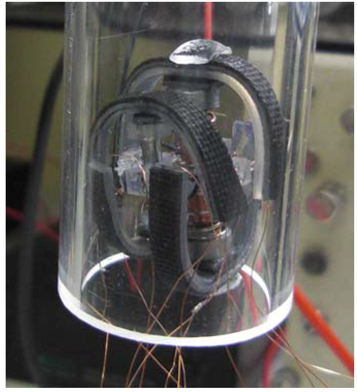
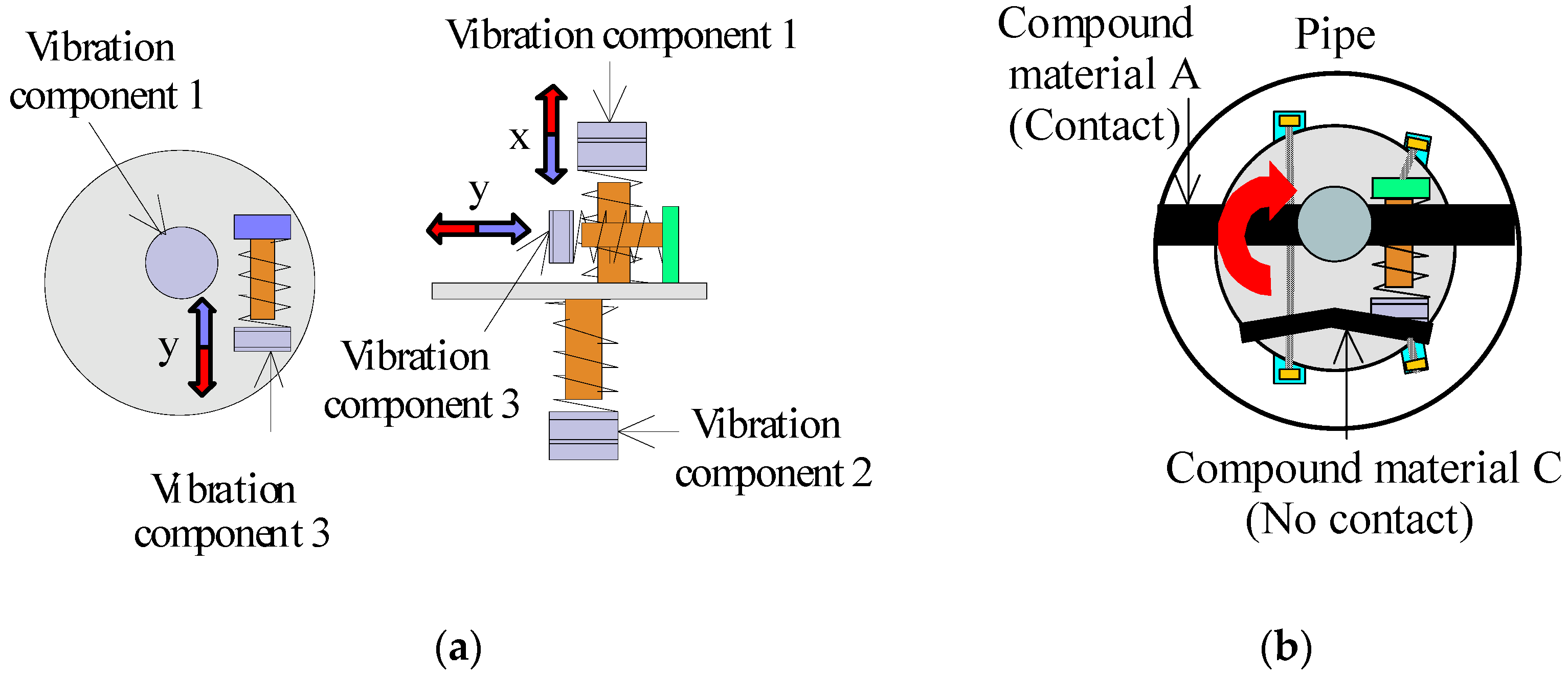
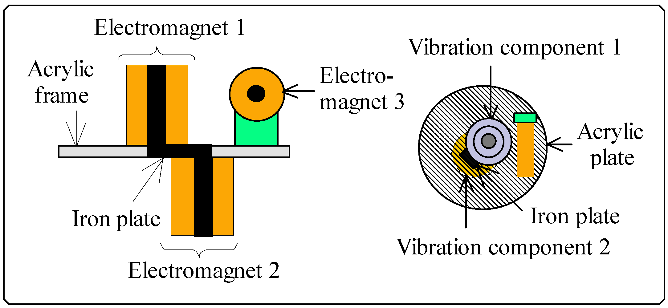
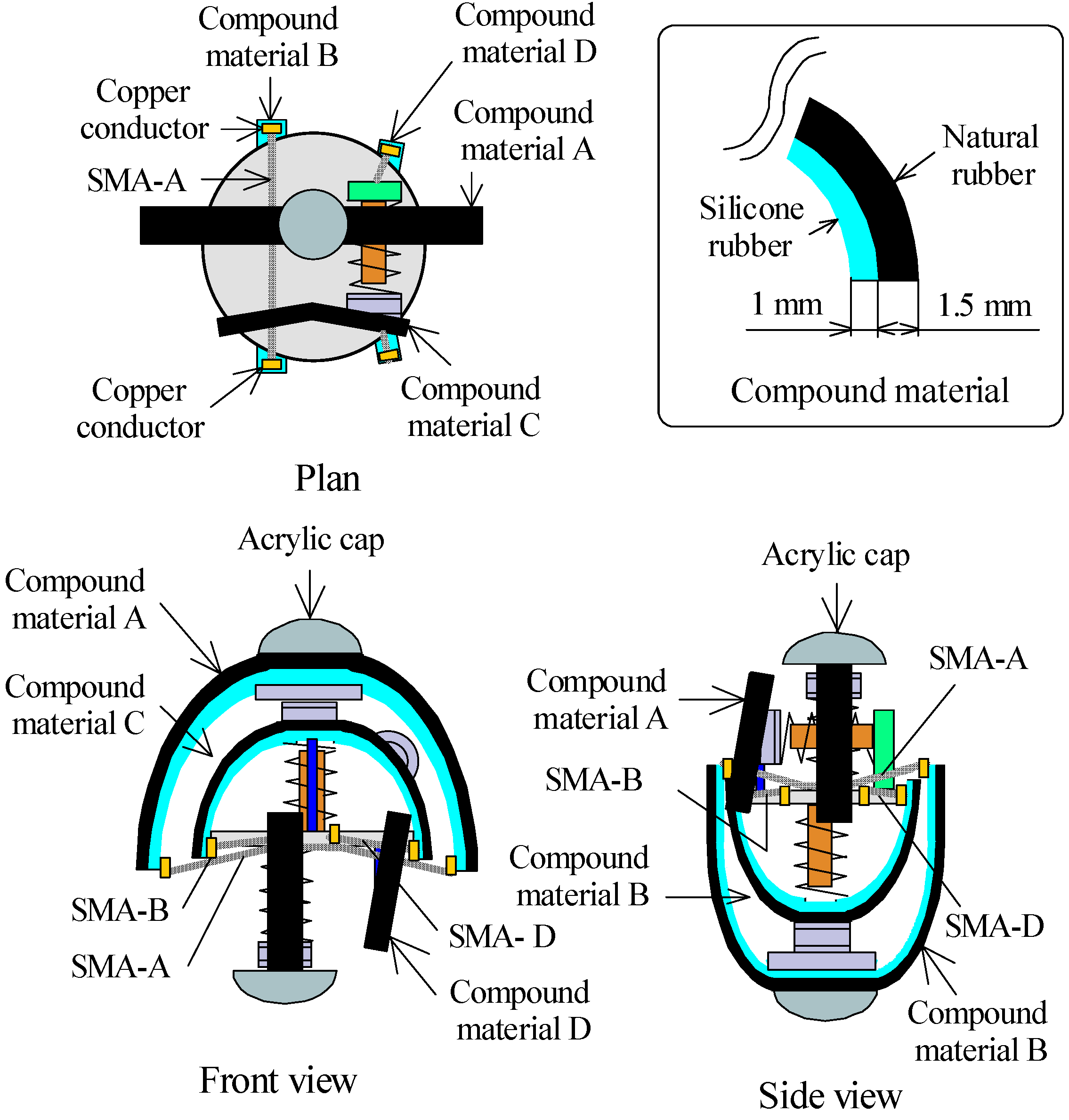
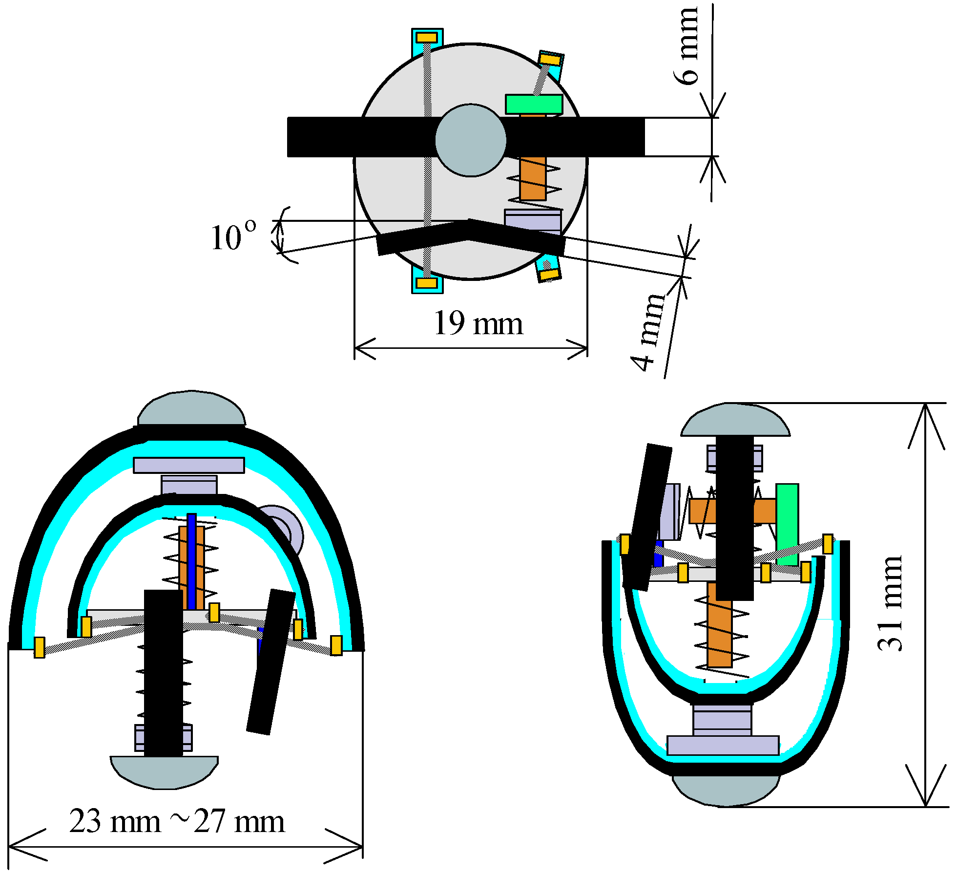
2. Structure of a Magnetic Actuator and Vibration Components
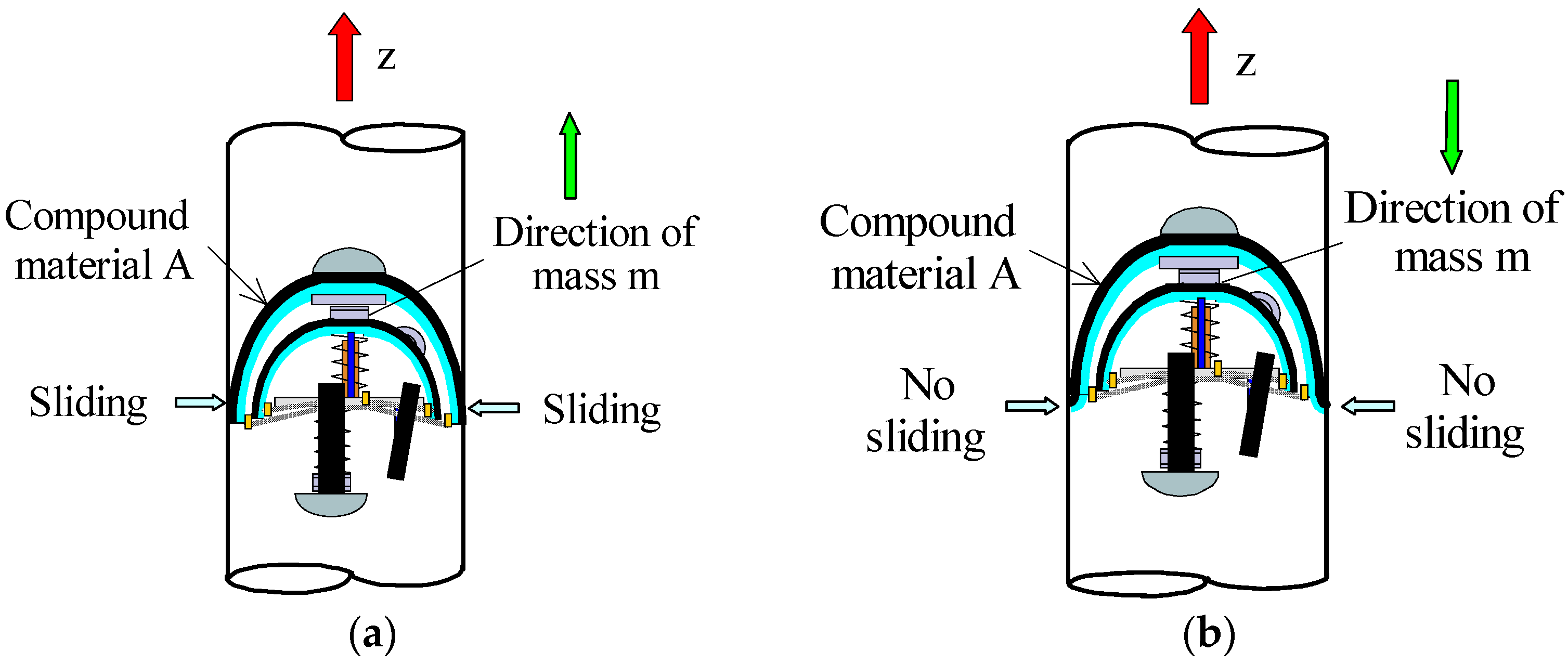
3. Principle of Linear and Rotational Motion
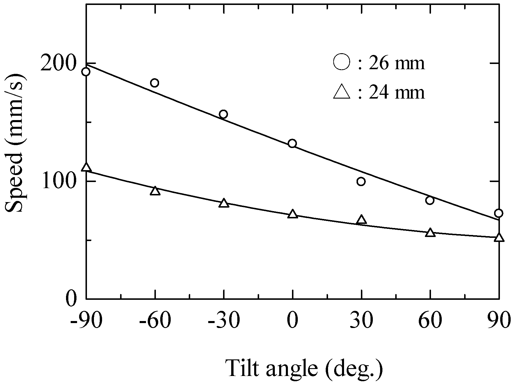
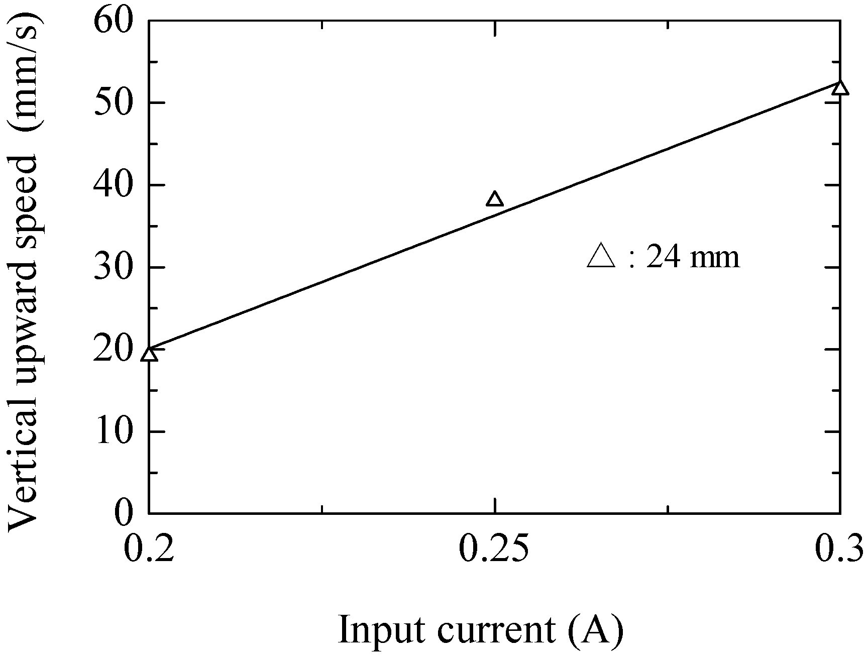
4. Basic Locomotive Characteristics of Magnetic Actuator
5. Movement in a Complex Pipe
6. Conclusions
Author Contributions
Conflicts of Interest
References
- Kurosumi, Y.; Yoshiara, T. Defect Identification of Carbon Steel Testpieces by Using Pattern Recognition through Ultrasonic Inspection. INSS J. 1995, 2, 127–137. [Google Scholar]
- Kalyanasundram, P. High Sensitivity Detection and Classification of Defects in Austenitic Weldments Using Cluster Analysis and Pattern Recognition. J. Nondestrct. Test. 1991, 33, 6. [Google Scholar]
- Junji, K.; Manabu, O.; Hiroshi, H. Multi-Bank Multi-Coil Probe for Heat Exchanger Tube Eddy Current Test using Uniform Eddy Current. Jpn. Soc. Non-Destr. Insp. 2004, 53, 366–372. [Google Scholar]
- TakagiI, T.; Endo, H. Eddy Current Technologies for Thick Metal Structures Institute of Fluid Science. Jpn. Soc. Non-Destr. Insp. 2014, 6, 10. [Google Scholar]
- Saito, H.; Sato, K.; Kudo, K.; Sato, K. Fundamental Study of Mover Travel inside a Small Diameter Pipe. Trans. Japan Soc. Mech. Eng. 2000, 66, 346–353. [Google Scholar] [CrossRef]
- Fujita, J.; Shiraogawa, Y.; Yamamoto, S.; Kato, T. Study of Mobile Mechanism with Elastic Fibers by Using Vibration. Trans. Japan Soc. Mech. Eng. 2004, 70, 22–26. [Google Scholar] [CrossRef]
- Kwon, J.; Park, S.; Kim, B.; Park, J. Bio-Material Property Measurement System for Locomotive Mechanism in Gastro-Intestinal Tract. In Proceedings of the IEEE International Conference on Robotics and Automation (ICRA), Barcelona, Spain, 18–22 April 2005; pp. 1315–1320.
- Reynaerts, D.; Peilw, J.; Van Brussel, H. Design of a Shape Memory Actuated Gastrointestinal Intervention System. In Proceedings of the 6th International Symposium on Micro Machine and Human Science, Leuven, Belgium, 8–11 September 1996.
- Kim, J.; Kim, M.J.; Yoo, J.; Kim, S.J. Novel Motion Modes for 2-D Locomotion of a Microrobot. IEEE Trans. Magn. 2014, 50. [Google Scholar] [CrossRef]
- Choi, K.; Jang, G.; Jeon, S.; Nam, J. Capsule-Type Magnetic Microrobot Actuated by an External Magnetic Field for Selective Drug Delivery in Human Blood Vessels. IEEE Trans. Magn. 2014, 50. [Google Scholar] [CrossRef]
- Kim, S.H.; Shin, J.W.; Ishiyama, K. Multiscale Magnetic Spiral-Type Machines for Fluid Manipulation. IEEE Trans. Magn. 2014, 50. [Google Scholar] [CrossRef]
- Guo, S.; Sawamoto, J.; Pan, Q. A Novel Type of Microrobot for Biomedical Application. In Proceedings of the 2005 IEEE/RSJ International Conference on Intelligent Robots and Systems (IROS2005), Edmonton, AB, Canada, 2–6 August 2005; pp. 2265–2270.
- Miyagawa, T.; Iwatski, N. Moving Characteristics in Bent Pipes of In-Pipe Mobile Robot with Wheel Drive Mechanism using Planetary Gear Drive. J. Jpn. Soc. Precis. Eng. 2008, 74, 1346–1350. [Google Scholar] [CrossRef]
- Guo, J.; Guo, S.; Wei, X.; Wang, Y. Development of Wireless Endoscope with Symmetrical Motion Characteristics. Int. J. Adv. Robot. Syst. 2014, 11. [Google Scholar] [CrossRef]
- Yaguchi, H.; Sato, N. Globular Magnetic Actuator Capable of Freely Movement in a Complex Pipe. IEEE Trans. Magn. 2010, 46, 1350–1355. [Google Scholar] [CrossRef]
- Yaguchi, H.; Sato, N.; Shikoda, A. Magnetic Actuator Group of Globular Type Capable of Free Movement in a Complex Pipe. IEEE Trans. Magn. 2011, 47, 4159–4162. [Google Scholar] [CrossRef]
- Yaguchi, H.; Kamata, K. In-piping Magnetic Actuator Capable of Inspection in a Thin Complex Pipe. Mech. Eng. Res. 2012, 2, 1–9. [Google Scholar] [CrossRef]
- Yaguchi, H.; Sasaki, K. New Type of Magnetic Actuator System for Inspection in a Complex Pipe. IEEE Trans. Magn. 2013, 47, 4159–4162. [Google Scholar] [CrossRef]
- Yaguchi, H. Magnetic Actuator Capable of Inspection in a Complex Pipe by Phase Control of Multiple Electromagnetic Vibration Components. IEEE Trans. Magn. 2015, 51. [Google Scholar] [CrossRef]
- Wang, Q.; Li, J.; Liu, Y.F.; Qian, Z.Q.; Cao, L.; Zhang, W.J. A Systematic and Rational Design Approach for Compliant Amplification Mechanisms. In Proceedings of the IEEE 10th Conference on Industrial Electronics and Applications, Auckland, New Zealand, 15–17 June 2015; pp. 74–78.


| Outer Diameter | Diameter of Wire | Transformation Point | Resistance Per Meter | |
|---|---|---|---|---|
| SMA coil | 0.62 mm | 150 μm | 60–65 °C | 400 Ω |
| Upward | Updown | Left | Right | |
|---|---|---|---|---|
| Pattern I (mm/s) | 43.8 | 88.8 | 63.5 | 70.8 |
| Pattern II (mm/s) | 42.2 | 67.5 | 57.3 | 53.1 |
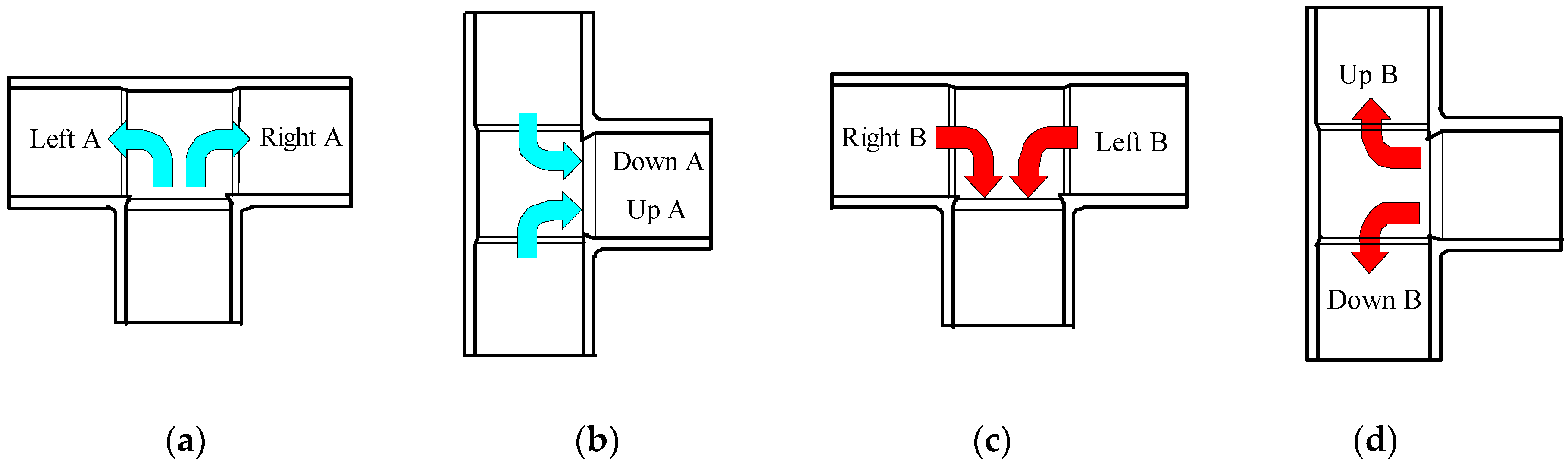
| Speed (mm/s) | Speed (mm/s) | ||
|---|---|---|---|
| Left A | 32.97 | Up A | 17.08 |
| Right A | 33.71 | Down A | 29.41 |
| Left B | 25.2 | Up B | 20.13 |
| Right B | 27.27 | Down B | 38.4 |
© 2016 by the authors; licensee MDPI, Basel, Switzerland. This article is an open access article distributed under the terms and conditions of the Creative Commons Attribution (CC-BY) license (http://creativecommons.org/licenses/by/4.0/).
Share and Cite
Yaguchi, H.; Kamata, K.; Sugawara, H. Magnetic Actuator with Multiple Vibration Components Arranged at Eccentric Positions for Use in Complex Piping. Actuators 2016, 5, 19. https://doi.org/10.3390/act5030019
Yaguchi H, Kamata K, Sugawara H. Magnetic Actuator with Multiple Vibration Components Arranged at Eccentric Positions for Use in Complex Piping. Actuators. 2016; 5(3):19. https://doi.org/10.3390/act5030019
Chicago/Turabian StyleYaguchi, Hiroyuki, Kazushige Kamata, and Hiroshi Sugawara. 2016. "Magnetic Actuator with Multiple Vibration Components Arranged at Eccentric Positions for Use in Complex Piping" Actuators 5, no. 3: 19. https://doi.org/10.3390/act5030019