1. Introduction
Piezoelectric actuators are well known for their high force density, high bandwidth, high resolution and ease of fabrication and excitation. They are the foremost actuators in Atomic Force Microscopy, and they are likely to remain the most widely used positioning actuators not only in AFMs, but also in other micro and nano scale positioning systems [
1,
2,
3,
4,
5,
6,
7,
8]. Piezoelectric actuators have evolved, after several decades of research and development, from their simple 1-DOF to multi-DOF micropositioners. They have several advantages over traditional motion-control devices, but also present challenges as they exhibit nonlinearities (creep and hysteresis) and badly damped vibrations not only in the direct transfers but also in the cross-coupling transfers which strongly affect the final performances and stability of these actuators. Many papers have dealt with the compensation against the nonlinearities and vibrations to improve actuator performance and accuracy [
5,
9,
10,
11,
12,
13,
14,
15]. One of the methods used to tackle vibrations of piezoelectric actuators was the feedforward input shaping method where the original input command is convolved with a set of impulses with different amplitudes to generate a new shaped command that is fed to the system input. The input shaping approach as a feedforward control configuration allows the avoidance of the use of sensors. This is particularity essential in applications where there is a great lack of sensors, like miniaturized systems for microassembly or micromanipulation. Additionally, the input shaping approach permits a reduction in the vibrations without substantially reducing the bandwidth, which is important in high dynamics positioning applications.
Input shaping has been given a great deal of consideration for single input systems with multiple modes of vibrations in time and frequency domains [
16,
17,
18,
19,
20,
21]. The newly formed commands for such systems are typically made by connecting single-mode impulse sequences in series. Singer [
19] demonstrated that shorter-length sequences would normally minimize distortion in the original command while removing all unwanted vibrations. Hyde [
17] extended Singer’s approach by using non-linear, numerical search algorithms to build time-optimal impulse sequences. As an alternate approach, Smith shown that Posicast inputs for multiple-mode systems could be built by placing zeros over all unwanted system poles in the z-plane. Smith suggested that the discrete transfer function resulting from the specified zeros could then be used to build a Posicast command to remove multiple-mode vibrations. Tuttle and Seering [
21] moved forward with what Smith suggested and proposed practical zero-placement technique to design optimal input shapers for systems with an arbitrary number of modes in the z-plane. In this technique, guidelines for effective strategy and simple shaper design to suppress vibrations become apparent. For systems with multiple inputs and multiple modes of vibrations, Pao [
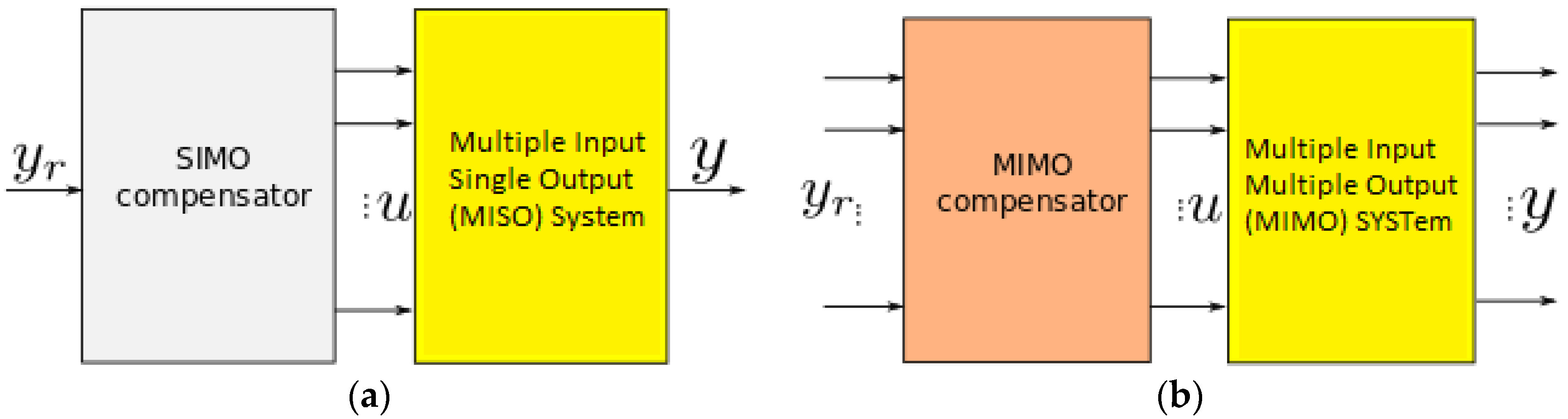
22] developed an input shaping design technique using pole placement in the s-plane which leads to a smaller number of impulses and therefore shorter shaping delay and faster maneuvering. In her approach, more information about the system model is taken into account and input shaping sequences for all system inputs are solved simultaneously, rather than solving them for each input independently of one another. However, the technique was only valuable for systems with single-output, although the input was multiple (see
Figure 1a). In [
23], we extended Pao’s technique to damp the vibrations in a 2-DOF piezoelectric actuator by segregating the system into two different subsystems, each with one output only.
This paper generalizes the work in [
23] so it can be applied to control the vibrations of multi-input and multi-output systems with multi modes of vibrations, see
Figure 1b. The results are important for piezoelectric actuators having several degrees of freedom and to which exploiting higher modes (and thus higher frequencies) is desired. We therefore apply the theoretical results to a 3-DoF piezoelectric tube actuator classically used in atomic force microscopes which demonstrates the effectiveness of this newly developed technique.
For the remainder of this paper, we briefly review the existing input shaping method for multiple input systems (but single output) in
Section 2. Then, the proposed extended approach for multiple input multiple output systems is outlined in
Section 3. Finally, in
Section 4, the theoretical results are adapted and applied to a 3-DoF piezoelectric actuator which demonstrates its efficiency to reduce the vibrations in both the direct transfers and in the cross-couplings.
2. Preliminaries on Multiple Input Shaping and Single Output Input Shaping Control
This section explains an approach to design input shapers for multi-input systems with multi-modes of vibrations using zero placement input shaping technique. The input shapers can be designed to be identical to each other by solving shaper constraint equations for only one sequence of impulses and applying the solution to all inputs, or by including more information about the system model into the problem formulation and solving for the impulse sequences simultaneously. The latter generally leads to shorter sequences [
22]. Let us assume a system with m + 1 input, single output, and n structural frequencies ɷ1… ɷn
where
For the rigid body
And
The problem of coupling among inputs is addressed by including information from the matrix of the system model in Equation (1) into the derivation of the designed shapers. Matrix A for each sub-system represents the modal modeling of the system which defines how the sub-system states are related to the modes of vibrations. Matrix A for the whole MIMO system contributes to the formulation of the transfer matrix from the unshaped inputs to the system states . The multiple input shaper transfer functions are , and is a vector containing them.
To filter out any vibrations due to the flexible mode, we choose
such that:
The desired impulse sequences (shapers) can then be solved for by taking the inverse Laplace transforms of
. If we assume the same T for all designed shapers then
can be written in the following form:
where
is the number of zeros that each of the shapers has.
For there will be an equal number of equations and unknowns, however this doesn’t mean that we have to satisfy this condition to solve for the shaper’s impulse amplitudes.
By substituting
in Equation (2), the constraint equations can be re-written in the following matrix form:
where
, and
can be solved using a generalized inverse:
As can be seen in this section, the design procedure of input shapers for systems with multiple inputs and one single output is straightforward, simple to implement, and easily adaptable to various types of robustness constraints. Further, the resulting shaper designs have fewer impulses per input, and lead to shorter shaper lengths, thus yielding faster output responses.
3. A Novel Multi-Mode MIMO Shaping Control
In this section, we explain how the same approach explained in
Section 2 can be extended and applied to multiple output systems with multi modes of vibrations. A multi-input multi-output system can be thought of as a number of sub-systems, each has the same number of inputs as the original system and only one output. The number of these resulting sub-systems is equal to the number of the original system’s outputs and each has its own shaper solution
. To be able to have one solution of shapers for all outputs, we have to include
information of all outputs in the shaper design process. That is, the designed shapers should be able to cancel all modes of vibrations for all outputs. This can be achieved by creating a new state vector
that includes all state vectors
where
represents the j
th output state vector.
The new input matrix can be expressed as the following:
where the number of inputs is
, the number of structural frequencies in each direction is
and the number of outputs is
.
As explained in [
23], for a system with two inputs
and two outputs
, each with two modes of vibrations
, the system input matrix for one of the outputs is:
and the system input matrix for both outputs will be:
For a system with three inputs
and three outputs
, each with three modes of vibrations
, the system input matrix for all outputs is:
The new resultant constraint matrix , where is the same matrix shown in Equation (5) for each of the outputs, taking into consideration that the unity constraint in each should not be repeated more than once in .
Including the newly formed input matrix B shown in Equation (8) in the problem solving would allow us to design a different shaper for each of the inputs. The newly formed P matrix shown in Equation (11), which can be constructed from B and sub-system poles, would ensure that the designed shapers will suppress all modes of vibrations for all outputs. The shaper amplitudes vector can be obtained from solvin .
As an example, for a two-input two-output system similar to the one in Equation (10) with two modes of vibration [
23], the
P matrix in Equation (11) becomes as shown in Equation (12). Where
and
are the structural frequencies and damping ratios for the first and second output respectively.
are system poles for the first output and
are system poles for the second output.
The generic
P matrix in Equation (11) allows us to design a compensator for any MIMO system with multiple modes of vibration. However, as the number of inputs, outputs or modes of vibration increase, the P matrix size becomes larger, and solving for shaper impulses becomes more challenging. The determination of this complexity is one of the perspective works. In the next section, we will apply the proposed generalized MIMO input shaping technique to a three-input three-output system with three modes of vibrations. The multi-mode in this context refers to the dominant resonance frequencies for each output of the MIMO system. The three-input three-output with three modes of vibration is not three SISO systems but rather it is, in our approach, three Multi Input Single Output (MISO) systems. Each of the outputs is coupled with all inputs through the
matrix [
23]. We will explain the MIMO system simplification in detail.
4. Applications to a 3-DOF Piezoelectric Actuator
4.1. Presentation of the Experimental Setup
In this section we apply the proposed multivariable input shaping control technique to reduce the vibrations in a piezoelectric actuator. The actuator to be characterized and controlled is a piezoelectric actuator having tubular structure, called piezoelectric tube or piezotube. Piezotubes exhibit badly damped oscillations in their responses to brusque or high frequency input signals. These oscillations, due to the high Q-factor and the cantilever structure nature, are undesirable since they increase the settling time of the actuators. Furthermore, the oscillations regrettably affect the final precision of the tasks. For instance, during an image scanning with an atomic force microscopy, the oscillations of the piezotube actuator introduce a deformation to the final image [
6,
24,
25]. Additionally, piezotubes also exhibit strong cross-couplings between the axes which contribute to more performances losses [
26,
27]. A novel multivariable input shaping control technique is therefore a good technique to damp the vibrations in such systems.
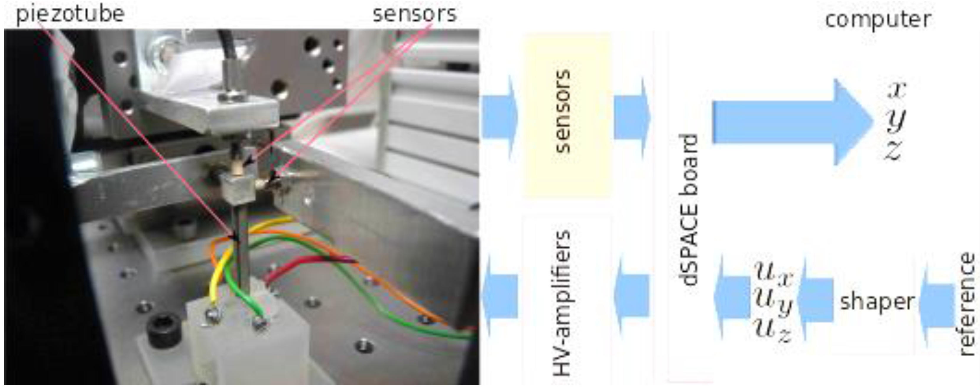
The experimental setup, depicted in
Figure 2, is composed of:
A piezoelectric actuator with a tubular structure, capable of deflecting along the x-axis, y-axis or z-axis when a voltage is applied to ux, uy or uz respectively. The piezotube (PT230.94 from PIceramic Company, Lederhosen, Germany) is 30 mm in length and has a 3.2 mm external diameter and can tolerate ±200 V voltages range.
Three inductive sensors (ECL202 from IBS company, Eindhoven, Netherlands) that are used to measure the displacements x, y and z. The sensors are tuned to have 40 nm of resolution, ±250 μm of measurement range and 15 kHz of bandwidth. Notice that the sensors are only used to characterize the oscillations of the actuator and to verify the performances of the control technique, they are not used to make a feedback control.
A computer and a dSPACE data acquisition board, which are used to manage the different signals (voltages, reference input and measured output) and to implement the input shaping controller. The sampling time is set to 50 μs, which is largely sufficient to consider the dynamics of the actuator in our case.
Three high-voltage (HV) amplifiers used to amplify the control signals ux, uz and uz from the dSPACE board before supplying the piezoactuator. The amplifiers can provide up to ±200 V.
4.2. Characterization and Modeling of the 3-DOF Piezoelectric Tube Actuator
The piezotube under test (shown in
Figure 2) was identified by firstly recording step responses for all of its three outputs when exciting each of x, y and z inputs separately , then plugging these recorded input and output traces to the MATLAB system identification toolkit to generate the best fit function that relates each output to each input. As a result, nine different transfer functions for the direct and cross couplings were derived. Thanks to the ARMAX (Auto Regressive Moving Average with eXternal inputs) system identification techniques [
28]. To be able to use the design approach explained in this paper, all of these transfer functions need to be reduced to second order transfer functions by only retaining dominant pole approximation.
4.3. Vibration Feedforward Controller Design
The system input matrix B (shown in Equation (10)) and the resultant poles from the reduced transfer functions are required for the formulation of the P matrix (shown in its generic form in Equation (11)). Since our system under test is a three-input three-output system, we have nine transfer functions and nine poles with their conjugates, as listed below:
| S1x = −326.7763621 + 5736.019955i; | | S1y = −238.7149106 + 5769.089347i; | | S1z = −632.18957547 + 4379.5395930i; |
| S1xc = −326.7763621 − 5736.019955i; | S1yc = −238.7149106 − 5769.089347i; | S1zc = −632.18957547 − 4379.5395930i; |
| S2x = −302.1598020 + 5803.751059i; | S2y = −184.4922971 + 7461.789129i; | S2z = −96.57235885 + 7522.7038840i; |
| S2xc = −302.1598020 − 5803.751059i; | S2yc = −184.4922971 − 7461.789129i; | S2zc = −96.57235885 − 7522.7038840i; |
| S3x = −35.84556158 + 1222.586399i; | S3y = −3.945002797 + 456.1052076i; | S3z = −39.356673163 + 15967.113359i; |
| S3xc = −35.84556158 − 1222.586399i; | S3yc = −3.945002797 − 456.1052076i; | S3zc = −39.356673163 − 15967.113359i; |
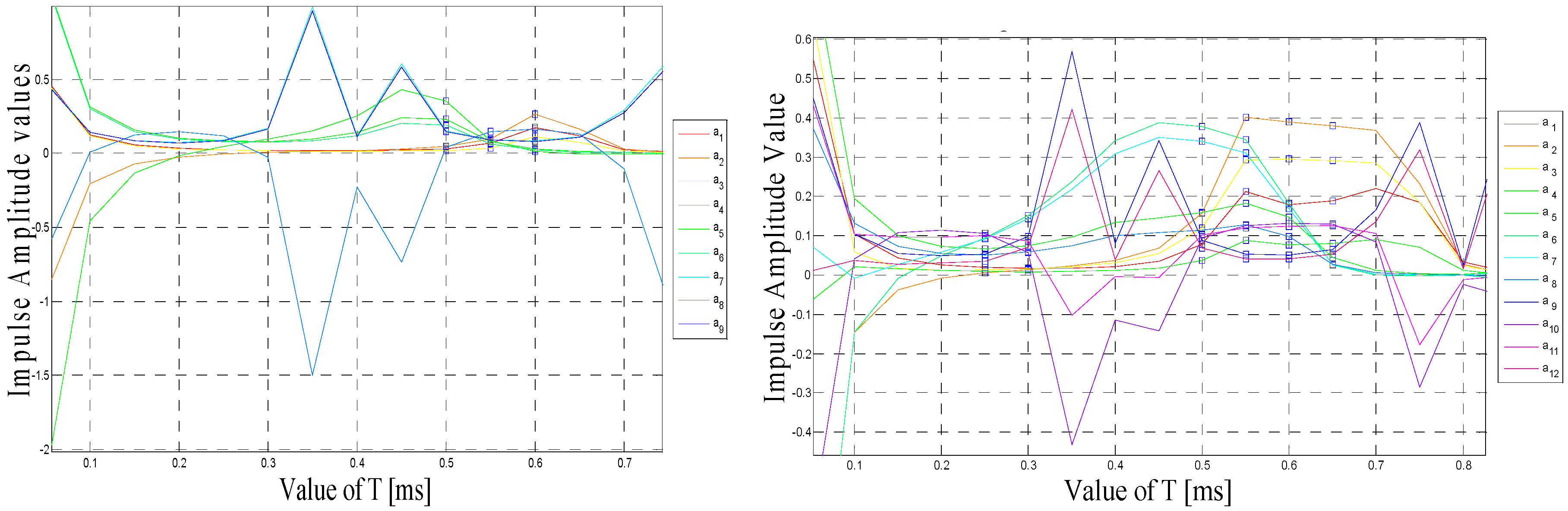
If we design all of the three input shapers with four impulses each, then vector
will be composed of 12 impulse amplitudes as per the following form:
These amplitudes can be calculated using Equation (7) which assumes that all impulses are evenly spaced and the spacing
T between them (which is the same for all shapers) has to be selected such that it is the minimum value
T to make all impulse amplitudes for all shapers positive. The goal is to make T as small as possible so the delay caused to the shaped (compensated) input is reduced. Solving Equation (7) yields an infinite number of solutions as a function of T. The desired one is the smallest value of T which satisfies the positive impulse condition. A simple MATLAB code was used to extract all of this information as shown in
Figure 3.
Figure 3 displays shaper impulse amplitudes
versus T, if we design the shapers with four impulses each then the first value to make all impulse amplitudes positive is T = 0.00025 s (
Figure 3, right-hand side) and as a result the calculated amplitude vector is:
Other values of
T for these four-impulse input shapers that satisfy the positive amplitudes condition are marked using square dots in
Figure 3 (right-hand side): 0.300, 0.500, 0.550, 0.600 and 0.650 ms.
For comparison purposes discussed in the next section, we also calculated vector
amplitudes when the shapers are designed with three impulses. As shown in
Figure 3 (left-hand side), the first
T to make all impulse amplitudes positive is T = 0.0005 s. For this T, the resultant impulse amplitudes vector is:
Other values of
T to satisfy the positive amplitudes condition for the three-impulse shapers are marked using square dots in
Figure 3-left: 0.500, 0.550 and 0.600 ms.
4.4. Simulation Results and Discussion
Once vector
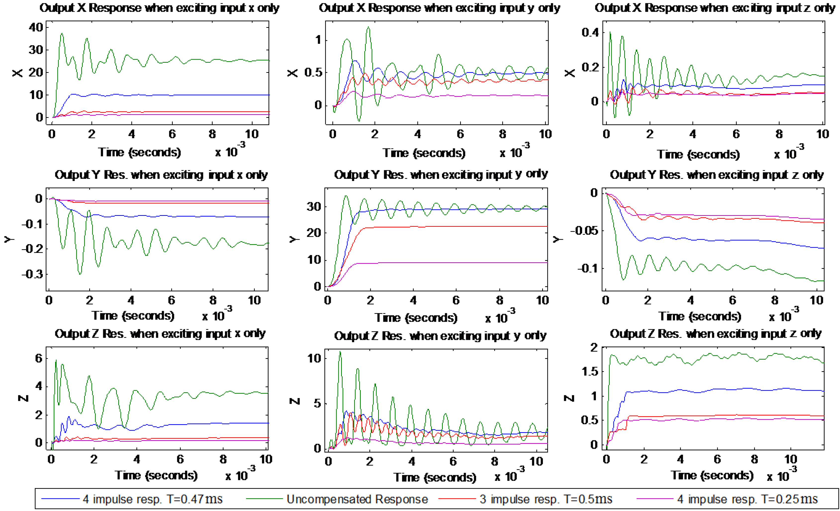
values are calculated, they can be plugged to the compensator design in SIMULINK to carry out the simulation.
Figure 4 shows simulated uncompensated and compensated responses when shapers were designed with three and four impulses. Each column in the figure shows one direct transfer and two cross couplings when exciting only one of the inputs. These simulation results show that the proposed MIMO controller was greatly successful in reducing vibrations and bringing them close to zero in both the direct and the cross-couplings for all outputs. However, it was not successful in obtaining the zero steady state error which is beyond the scope of this paper. It is also worth mentioning that having steady state error could be beneficial to reducing the level of cross couplings between inputs and outputs. Additionally, the four impulses shapers did a better job than the three impulses shapers in removing more modes of vibrations which can be attributed to the fact that the higher the number of impulses is for a shaper, the more it becomes robust against model uncertainties and the more it is effective in suppressing multi modes of vibrations. Having T = 0.25 ms for the four-impulses shapers which is half of T = 0.5 ms for the three-impulses shapers contributed to a shorter delay in the responses of the four-impulse shapers, although they have more impulses. Additionally, four-impulses shapers showed improved settling time over three-impulses shapers, as shown in
Table 1 below. Nevertheless, increasing the number of impulses for shapers further made it very challenging to find the proper and small
T value that would make all shaper impulse amplitudes positive and this can be considered as a limitation for this approach. For five-impulse shapers, the designed compensator was not able to find
T that satisfies the positive impulse amplitudes condition.
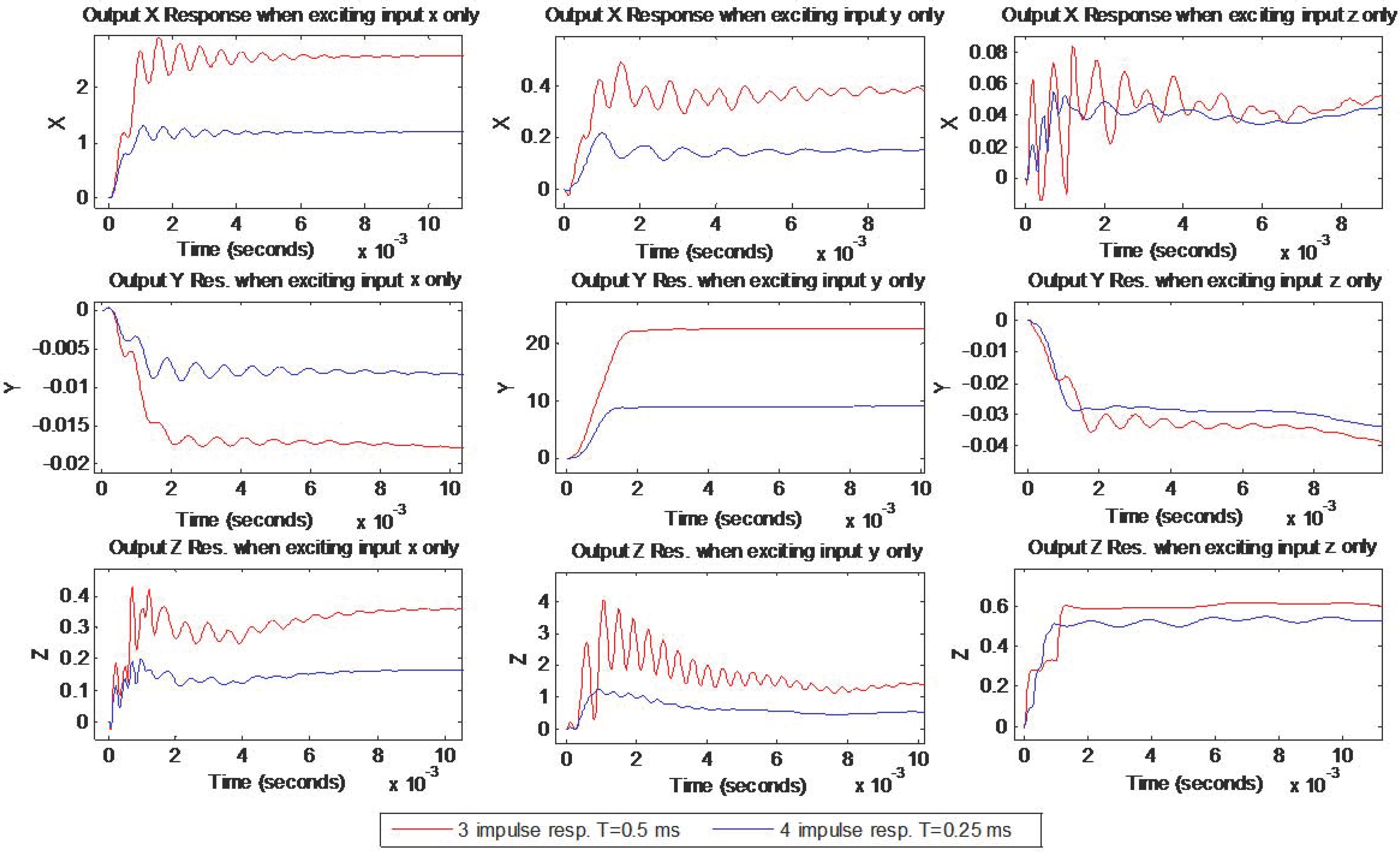
A closer look at the simulated three and four impulse shaper responses is shown in
Figure 5 below. It is obvious that four-impulses shaper responses have less delay and better vibrations suppression in both direct and cross couplings.
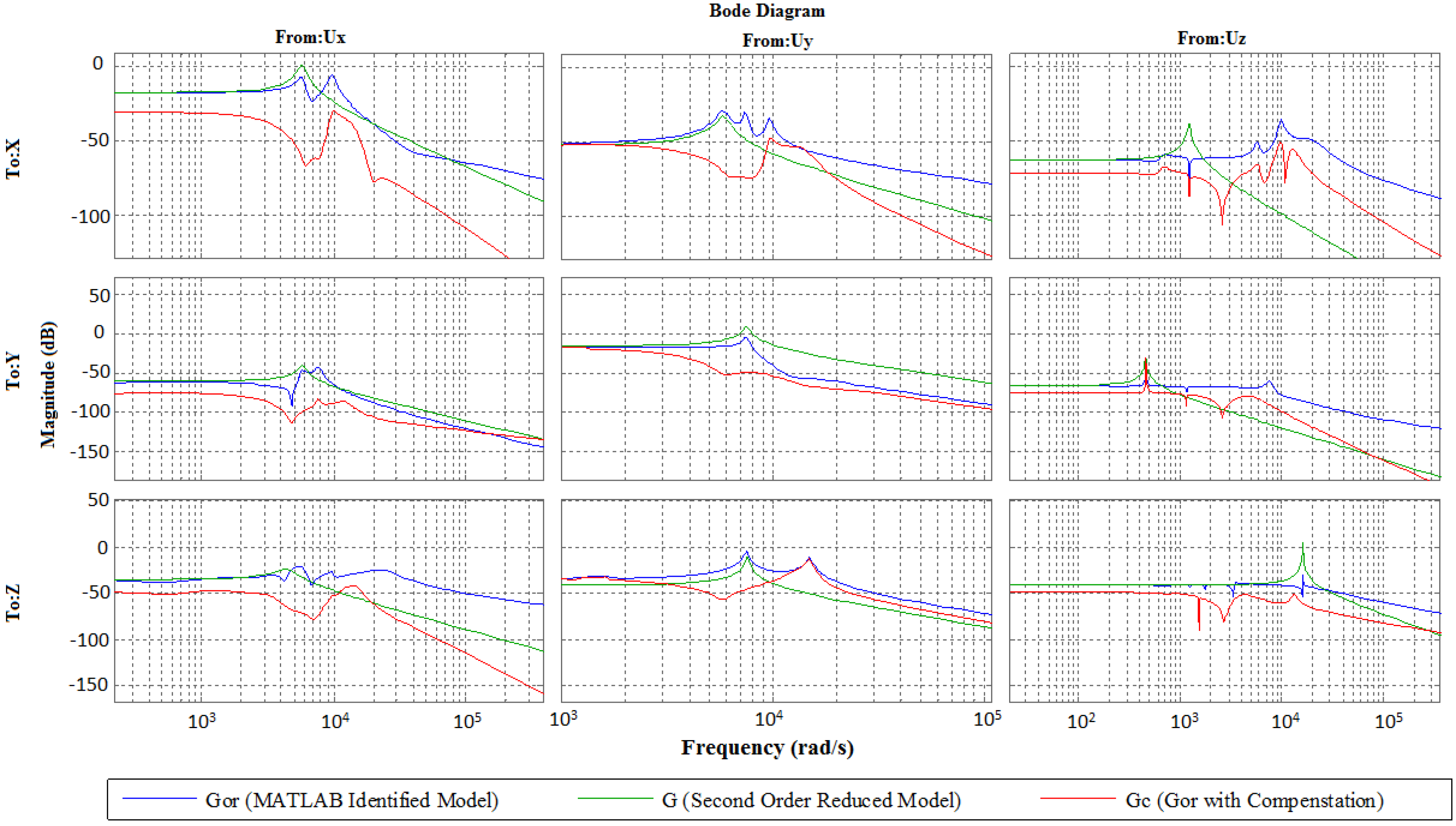
The vibrations suppression accomplished by the compensator can also be seen in the frequency domain, as shown in
Figure 6 below. Our approach relies on picking the dominant poles for each output and including them in the problem solving, and this can be much affected by the way the system modeling is carried out. However, in our next work we intend to make the design robust to uncertainties in such frequencies so the suppression becomes much more effective when the compensator is augmented in the feedforward.
4.5. Experimental Results
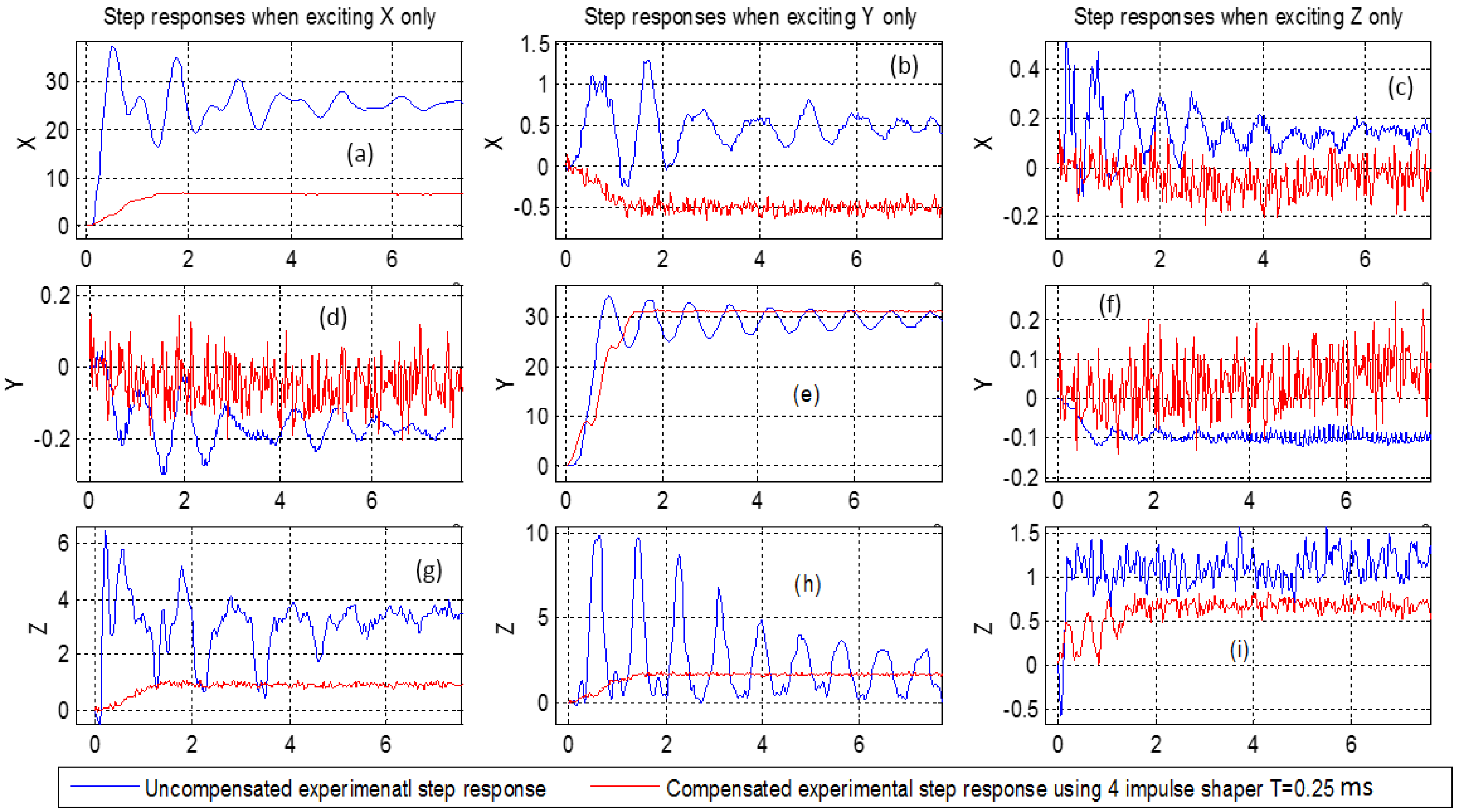
The designed compensator based on the four-impulses shaper is now applied to the experimental benchmark, composed of the 3-DOF piezoelectric actuator. First, a step input is applied to excite the x-axis by letting the excitation input along y and z axes be zero. The x-displacement is measured afterwards. We obtain the step response in
Figure 7a which corresponds to the direct transfer along the x-axis. In the meantime, the displacements along the y and z axes are recorded and plotted. They are shown in
Figure 7d (for the y axis) and
Figure 7g (for the z axis). These two last responses correspond to the cross-couplings. The same procedure is applied for the y excitation (by letting the x and the z excitations zero) and for the z excitation (by letting the x and the y excitations zero).
Figure 7e,i represent the direct transfers along the y and the z axes respectively. The remaining curves are the cross-couplings. The uncompensated responses are also pictured in the same figures. These figures clearly demonstrate that badly damped oscillations of the actuator are strongly reduced when applying the proposed compensator, both for the direct transfers and for the cross-couplings. As predicted by the simulation, the overshoots which reached 400% (see
Figure 7h) were completely removed.
5. Conclusion and Perspectives
This paper generalized a feedforward vibration suppression technique for multiple-input multiple-output systems with multi modes of vibrations found in cantilever structured piezoelectric actuators. We proposed to extend the multi-input-single-output zero placement input shaping technique into multi-input-multi-output technique. The proposed approach permits us to reduce multi-modes vibrations in both the direct and cross-couplings transfers. The new approach only requires knowledge of the system input matrix and system poles information for the design of the compensator which makes it a straightforward and easy design approach. The new approach was afterwards applied to feedforward control of a 3-DOF piezoelectric tube actuator that exhibits strong vibrations and strong cross-couplings. The simulation and experimental results demonstrated its efficiency, permitting us to completely remove overshoots of the actuator, initially of 400%. The proposed MIMO feedforward control of vibrations is very promising for systems where using sensors is difficult or even impossible. The proposed results can also be used to ease the calculation of a feedback controller by firstly removing the vibrations.
Acknowledgments
This work is supported by the National ANR-JCJC C-MUMS project (ANR-12-JS03007.01) and by the Labex-ACTION project (ANR-11- LABX-0001-01).
Author Contributions
Both authors designed the controllers, implemented the experiments and wrote the paper.
Conflicts of Interest
The authors declare no conflict of interest.
References
- Abramovitch, D.Y.; Andersson, S.B.; Pao, L.Y.; Schitter, G. A tutorial on the mechanisms, dynamics, and control of Atomic Force Microscopes. In Proceedings of the American Control Conference, New York, NY, USA, 9–13 July 2007.
- Kuiper, S.; Schitter, G. Active damping of a piezoelectric tube scanner using self-sensing piezo actuation. Mechatronics 2010, 20, 656–665. [Google Scholar] [CrossRef] [PubMed]
- Binnig, G.; Quate, C.F.; Gerber, C. Atomic Force Microscope. Phys. Rev. Lett. 1986, 56, 930–933. [Google Scholar] [CrossRef] [PubMed]
- Agnus, J.; de Lit, P.; Chaillet, N. Micromanipulateur piézoélectrique notamment pour microrobotique. French Patent FR0211934, 2002. [Google Scholar]
- Agnus, J.; Chaillet, N.; Clévy, C.; Dembélé, S.; Gauthier, M.; Haddab, Y.; Laurent, G.; Lutz, P.; Piat, N.; Rabenorosoa, K.; et al. Robotic Microassembly and Micromanipulation at FEMTO-ST. J. Micro-Bio. Robot. 2013, 8, 91–106. [Google Scholar] [CrossRef] [Green Version]
- Rakotondrabe, M. Smart Materials-Based Actuators at the Micro/Nano-Scale: Characterization, Control and Applications; Springer-Verlag: New York, NY, USA, 2013. [Google Scholar]
- Xie, H.; Rakotondrabe, M.; Régnier, S. Characterizing piezoscanner hysteresis and creep using optical levers and a reference nanopositioning stage. Rev. Sci. Instrum. 2009, 80, 046102. [Google Scholar] [CrossRef] [PubMed] [Green Version]
- Rakotondrabe, M.; Haddab, Y.; Lutz, P. Development, Modeling, and Control of a Micro-/Nanopositioning 2-DOF Stick–Slip Device. IEEE/ASME Trans. Mechatron. 2009, 14, 733–745. [Google Scholar] [CrossRef] [Green Version]
- Rakotondrabe, M.; Agnus, J.; Lutz, P. Feedforward and IMC-Feedback Control of a Nonlinear 2-DOF Piezoactuator Dedicated to Automated Micropositioning Tasks. In Proceedings of the IEEE-CASE, International Conference on Automation Science and Engineering, Trieste, Italy, 24–27 August 2011; pp. 393–398.
- Rakotondrabe, M.; Clévy, C.; Lutz, P. Hysteresis and vibration compensation in a nonlinear unimorph piezocantilever. In Proceedings of the IEEE/RSJ-IROS International Conference on Intelligent Robots and Systems, Nice, France, 22–26 September 2008; pp. 558–563.
- Rakotondrabe, M. Bouc-Wen modeling and inverse multiplicative structure to compensate hysteresis nonlinearity in piezoelectric actuators. IEEE Robot. Autom. Soc. 2011, 8, 428–431. [Google Scholar] [CrossRef] [Green Version]
- Croft, D.; Shed, G.; Devasia, S. Creep, hysteresis and vibration compensation for piezoactuators: Atomic force microscopy application. ASME J. Dyn. Syst. Meas. Control. 2001, 123, 35–43. [Google Scholar] [CrossRef]
- Rakotondrabe, M. Classical Prandtl-Ishlinskii modeling and inverse multiplicative structure to compensate hysteresis in piezoactuators. In Proceedings of the ACC American Control Conference, Montreal, QC, Canada, 27–29 June 2012; pp. 1646–1651.
- Rakotondrabe, M. Modeling and Compensation of Multivariable Creep in multi-DOF Piezoelectric Actuators. In Proceedings of the IEEE ICRA International Conference on Robotics and Automation, Saint Paul, MN, USA, 14–18 May 2012; pp. 4577–4581.
- Habineza, D.; Rakotondrabe, M.; Le Gorrec, Y. Simultaneous Suppression of Badly-Damped Vibrations and Cross-couplings in a 2-DoF piezoelectric actuator, by using Feedforward Standard H∞ approach. Proc. SPIE 2015, 9494. [Google Scholar] [CrossRef]
- Bhat, S.P.; Miu, D.K. Solutions to Point-to-Point Control Problems Using Laplace Transform Technique. ASME J. Dyn. Syst. Meas. Control 1991, 113, 425–431. [Google Scholar] [CrossRef]
- Hyde, J.M.; Seering, W.P. Using Input Command Pre-Shaping to Suppress Multiple Mode Vibration. In Proceedings of the IEEE Robotics and Automation Conference, Sacramento, CA, USA, 9–11 April 1991; pp. 2604–2609.
- Singer, N.; Seering, W.P. Preshaping Command Inputs to Reduce System Vibration. ASME J. Dyn. Syst. Meas. Control 1990, 12, 76–82. [Google Scholar] [CrossRef]
- Rappole, B.W.; Singer, N.C.; Seering, W.P. Multiple-Mode Input Shaping Sequences for Reducing Residual Vibrations. In Proceedings of the 23rd Biennial Mechanisms Conference, Minneapolis, MN, USA, 11–14 September 1994; pp. 11–16.
- Singh, T.; Vadali, S.R. Robust Time-Optimal Control: A Frequency Domain Approach. Proc. AZAA Guid. Navig. Control Conf. 1994. [Google Scholar] [CrossRef]
- Tuttle, T.D.; Seering, W.P. A Zero-Placement Technique for Designing Shaped Inputs to Suppress Multiple-mode Vibration. Proc. Am. Control Conf. 1994, 3, 2533–2537. [Google Scholar]
- Pao, L.Y. Multiple Input-Shaping Design for Vibration Reduction. Automatica 1999, 35, 81–89. [Google Scholar] [CrossRef]
- Al Hamidi, Y.; Rakotondrabe, M. Multi-Mode Vibration Suppression in 2-DOF Piezoelectric Systems Using Zero Placement Input Shaping Technique. Proc. SPIE 2015, 9494. [Google Scholar] [CrossRef]
- Santosh, D.; Evangelos, E.; Moheimani, S.O.R. A Survey of Control Issues in Nanopositioning. IEEE Trans. Control Syst. Technol. 2007, 15, 802–823. [Google Scholar]
- Das, S.K.; Pota, H.R.; Petersen, I.R. Resonant controller design for a piezoelectric tube scanner: A mixed negative-imaginary and small-gain approach. IEEE Trans. Control Syst. 2014. [Google Scholar] [CrossRef]
- Habineza, D.; Rakotondrabe, M.; Le Gorrec, Y. Bouc-Wen Modeling and Feedforward Control of multivariable Hysteresis in Piezoelectric Systems: Application to a 3-DoF Piezotube Scanner. IEEE Trans. Control Syst. Technol. 2015, 23, 1797–1806. [Google Scholar] [CrossRef]
- Habineza, D.; Rakotondrabe, M.; Le Gorrec, Y. Characterization, Modeling and H∞ Control of n-DOF Piezoelectric Actuators: Application to a 3-DOF Precise Positioner. Asian J. Control 2016, 18, 1–20. [Google Scholar]
- Ljung, L. System Identification Toolbox. The Matlab User’s Guide; MathWorks: Natick, MA, USA, 1995. [Google Scholar]
© 2016 by the authors; licensee MDPI, Basel, Switzerland. This article is an open access article distributed under the terms and conditions of the Creative Commons Attribution (CC-BY) license (http://creativecommons.org/licenses/by/4.0/).


