
Status and Perspectives of Multiferroic Magnetoelectric Composite Materials and Applications

Abstract
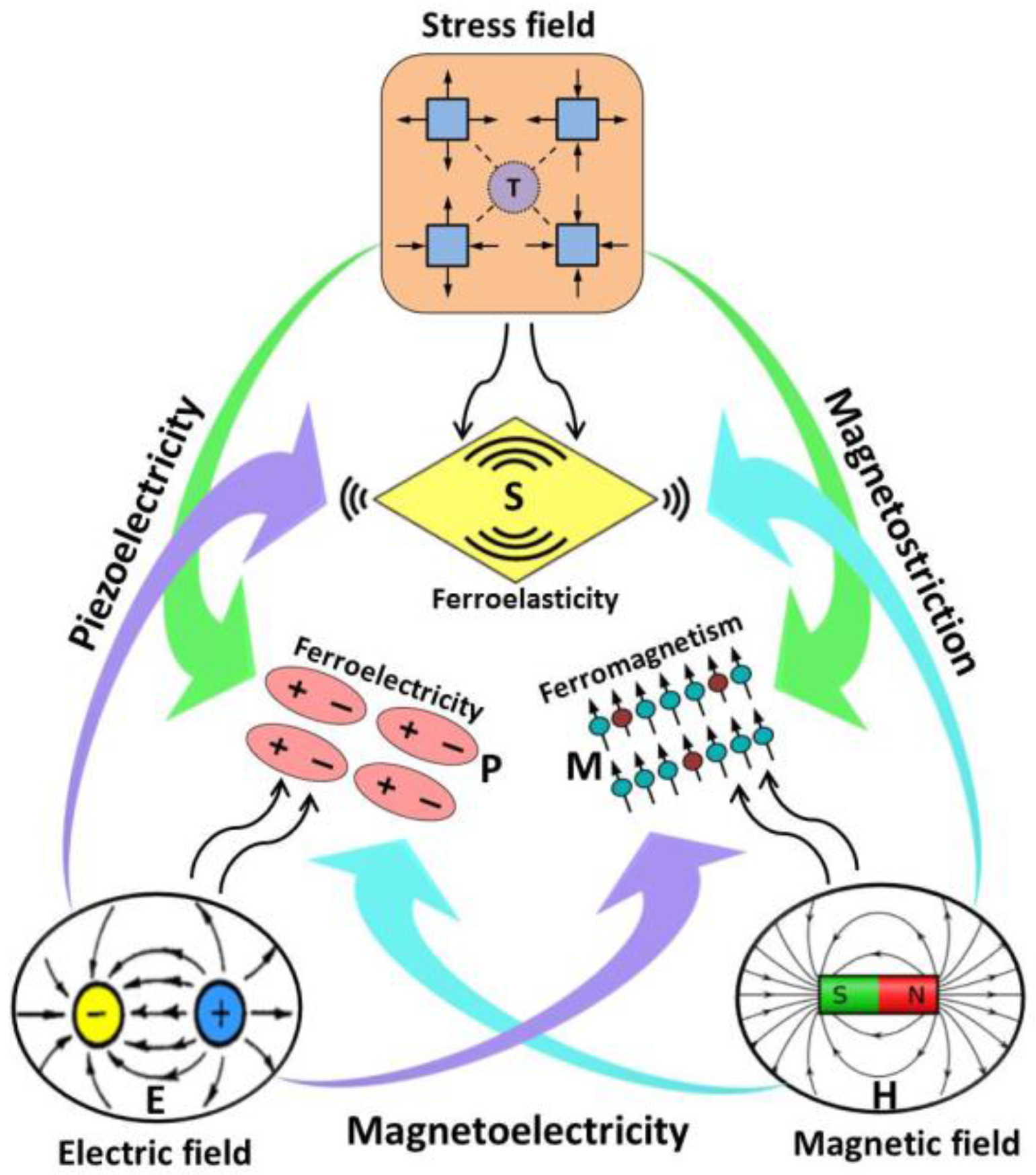
:1. Introduction
2. Factors Affecting ME Coupling in Composites
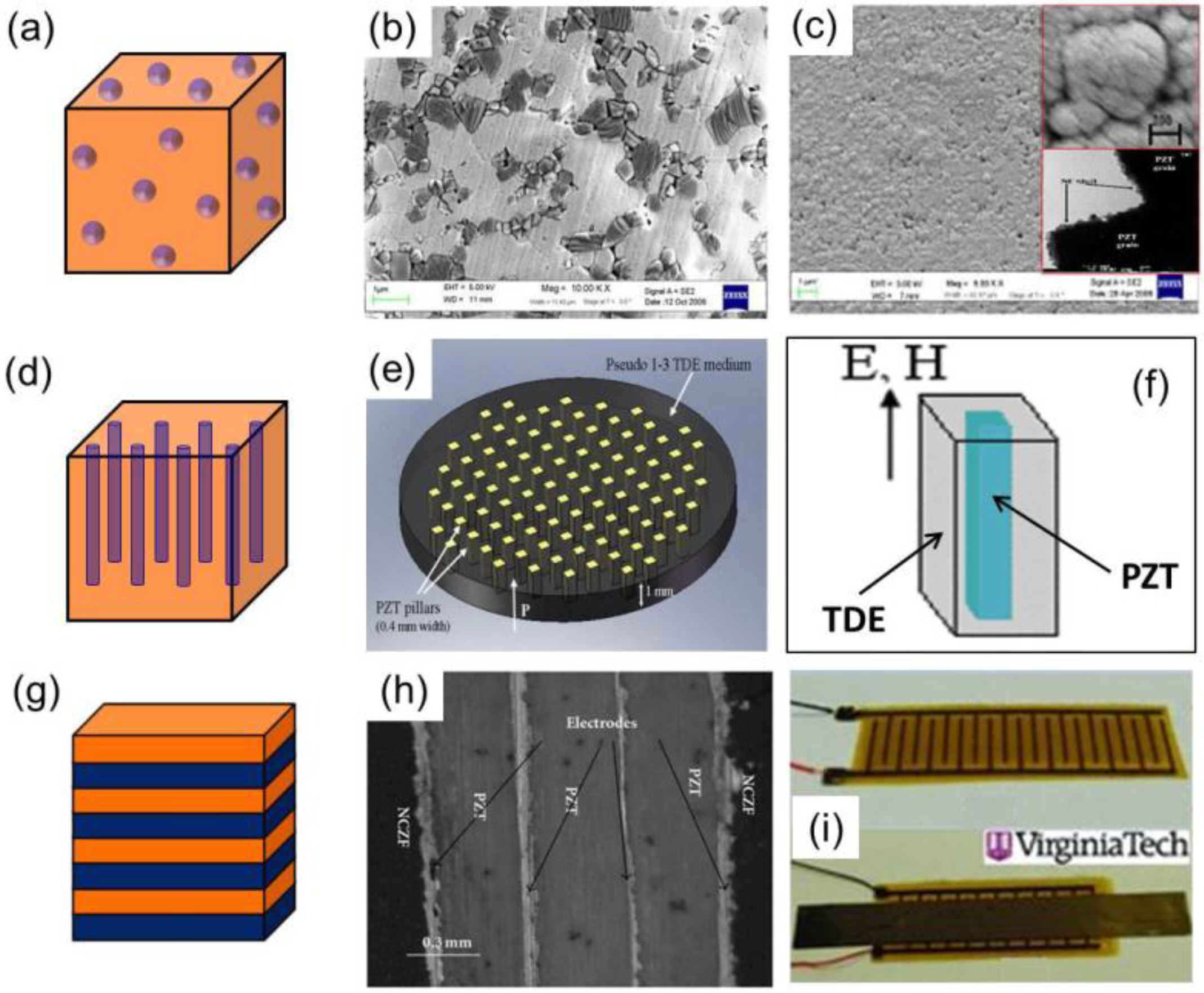
2.1. Connectivity and Interface Bonding
2.2. Materials and Their Properties
2.3. Fabrication of ME Composites
2.3.1. Bulk ME Composites
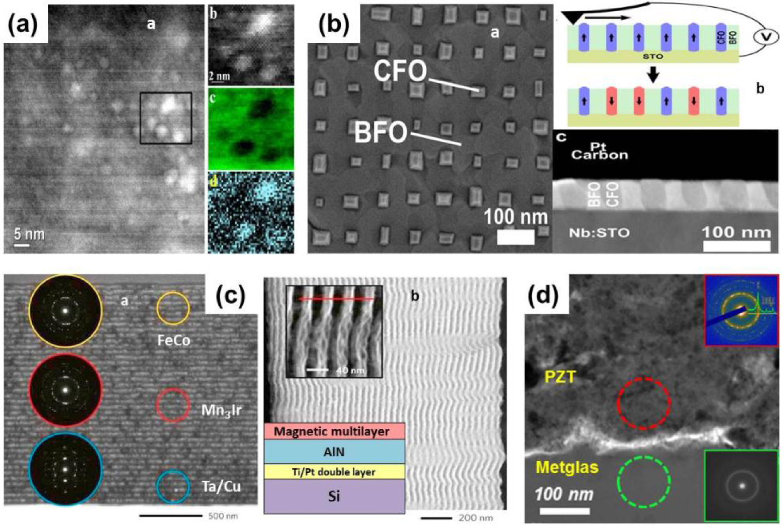
2.3.2. Film-Based ME Composites
3. Recent Advances in the Development of ME Composites
3.1. Realization of Broadband ME Response with Piezoelectric Anisotropy
3.2. ME Composites with Textured Piezoelectric Ceramics
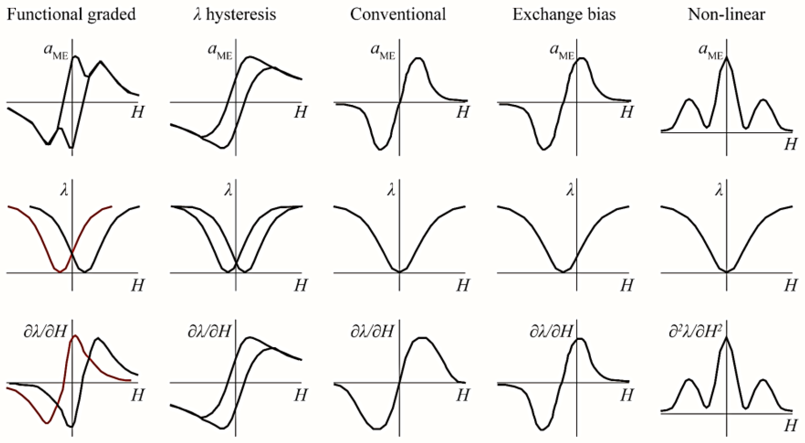
3.3. Self-Biased ME Composites
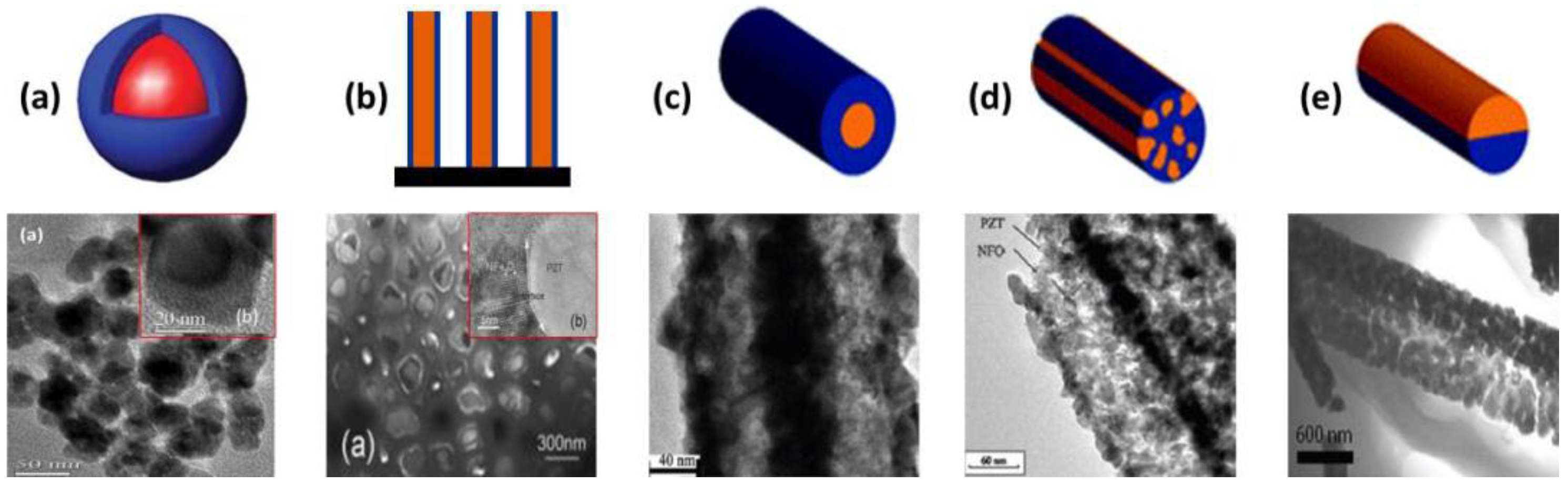
3.4. ME Composites with Novel Structures
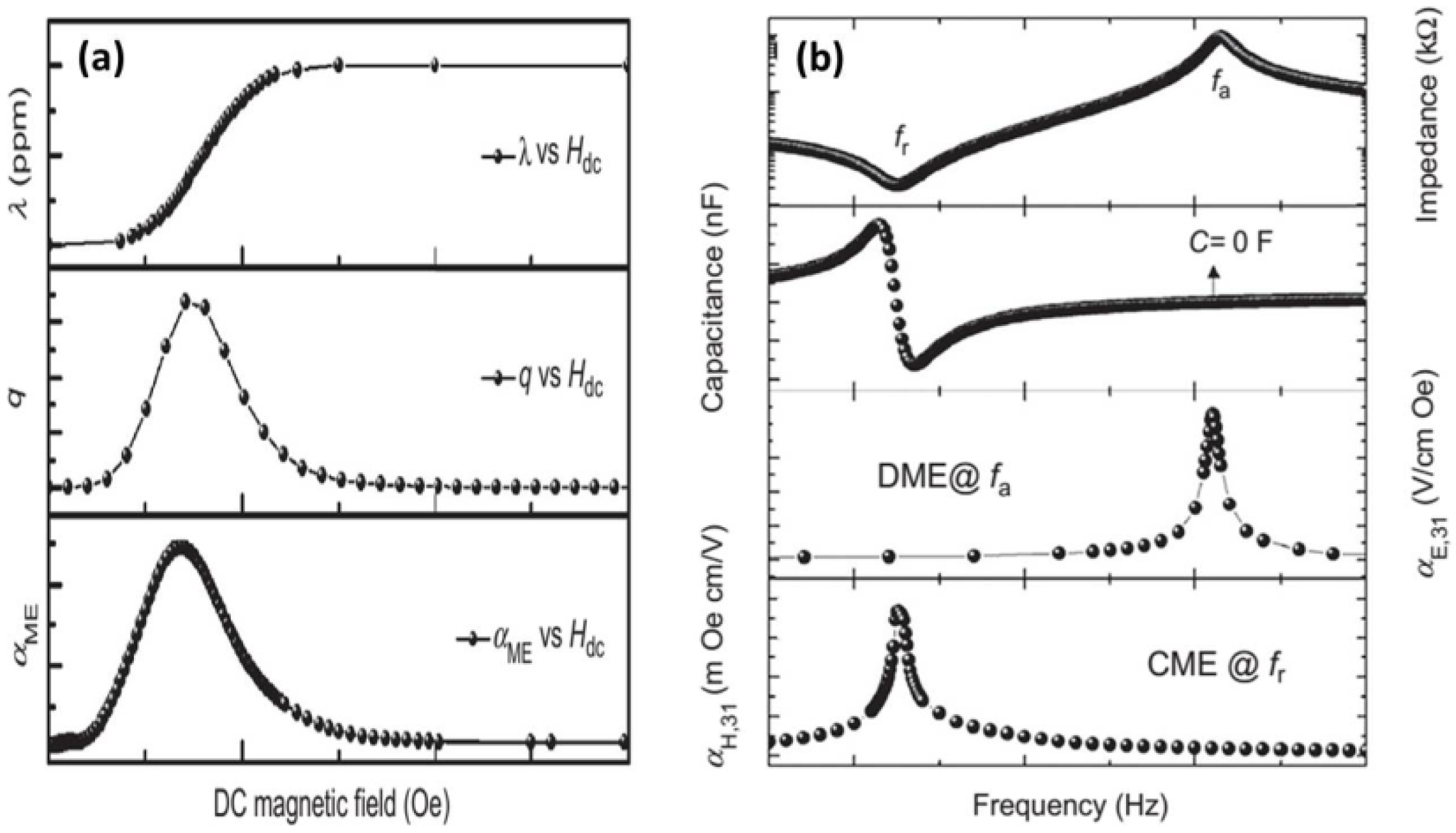
4. Characterization of ME Coupling
5. Magnetoelectric Devices and Applications
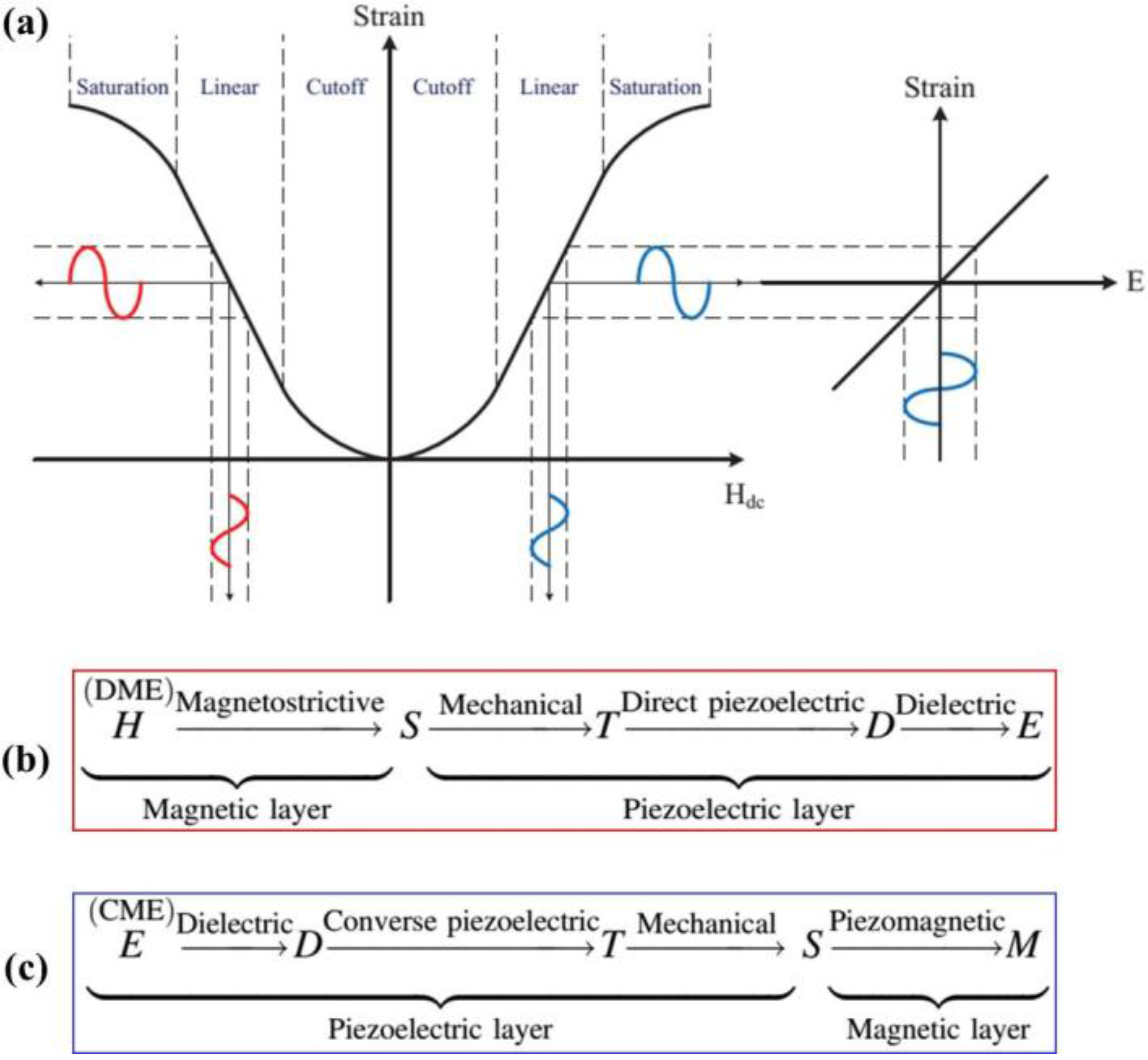
5.1. Devices Based on the DME Effect
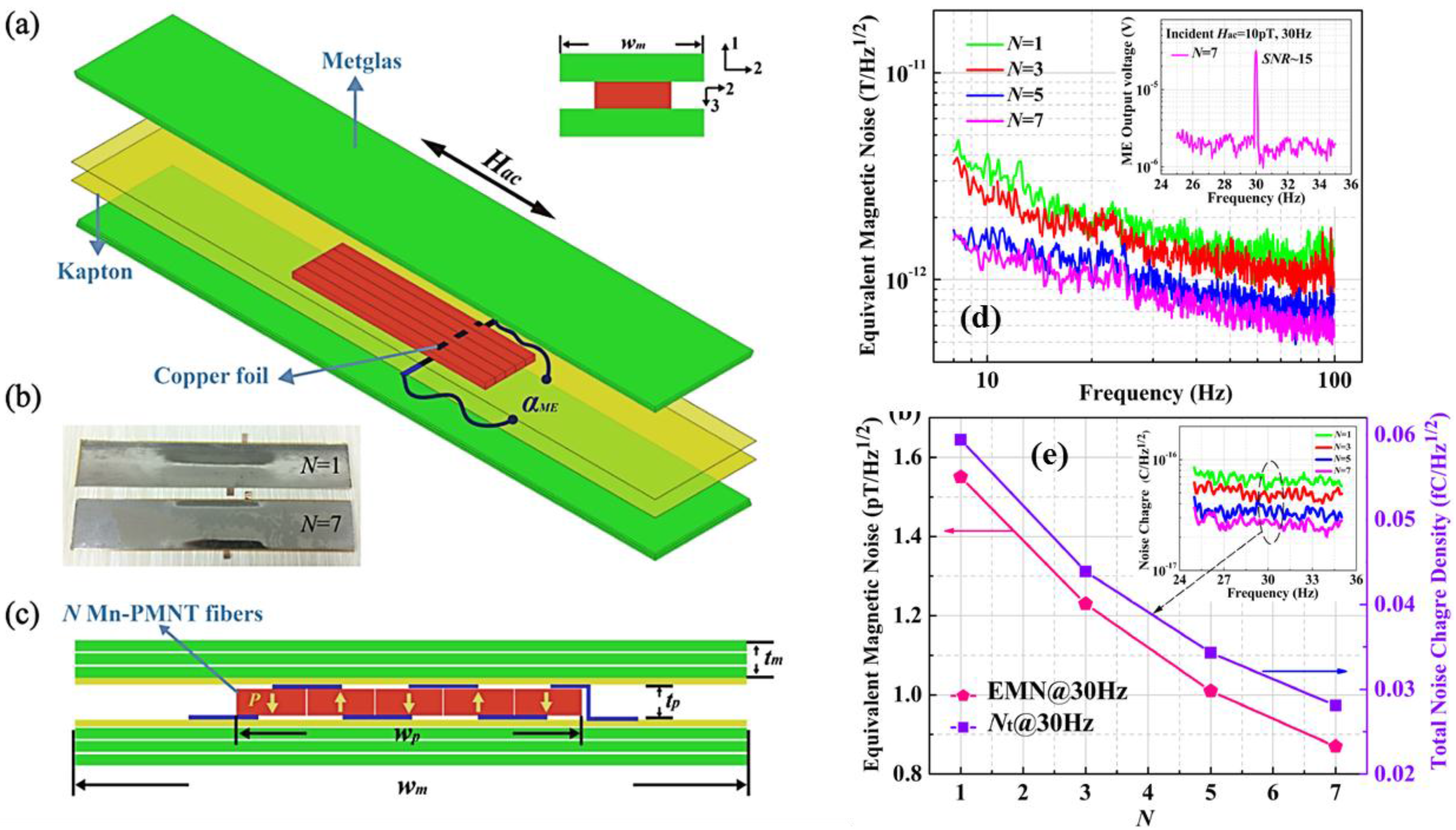
5.1.1. Magnetic Field Sensors
5.1.2. Electric Current Sensors
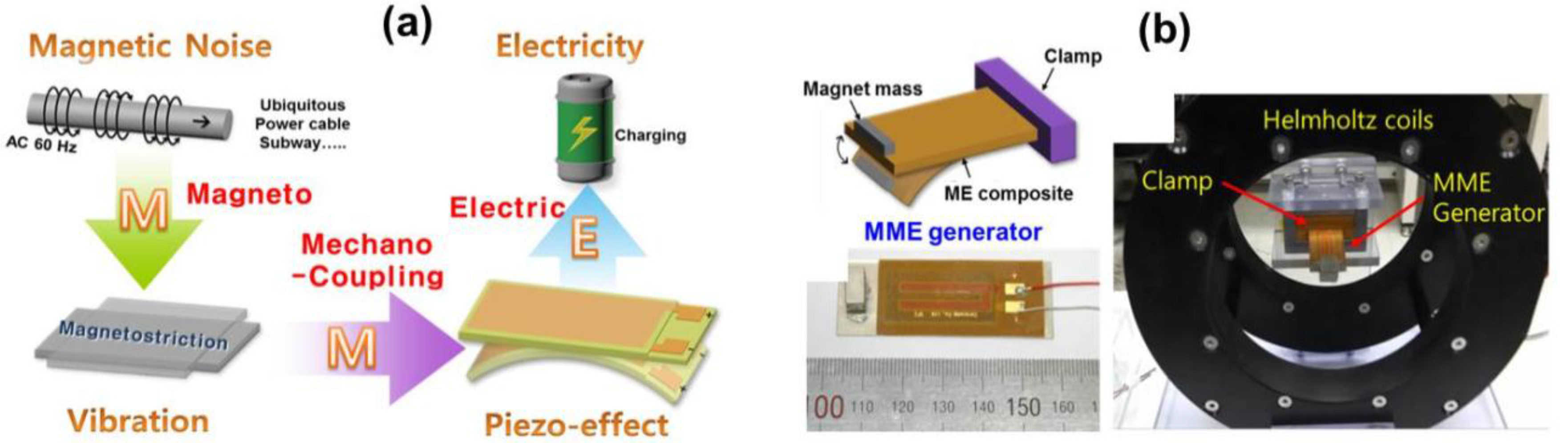
5.1.3. Energy Harvesters
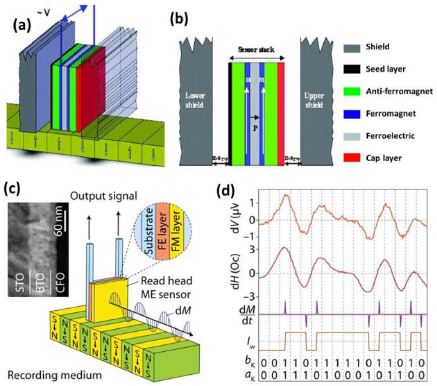
5.1.4. Magnetic Recording Read Head
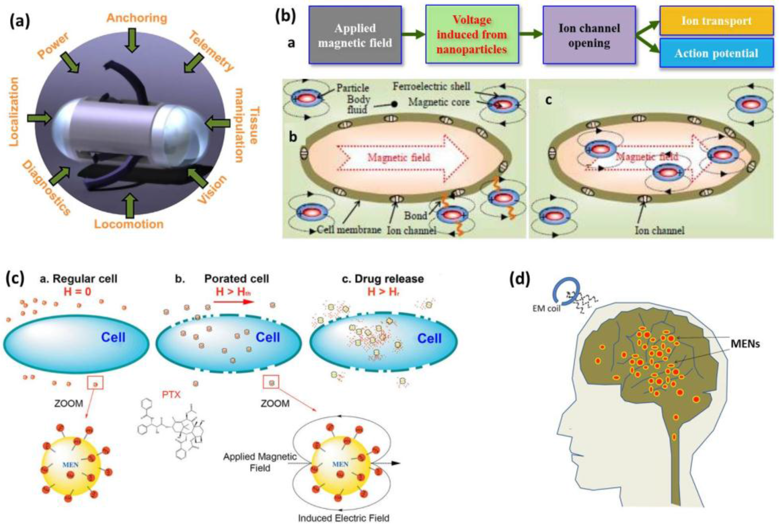
5.1.5. Biomedical Applications
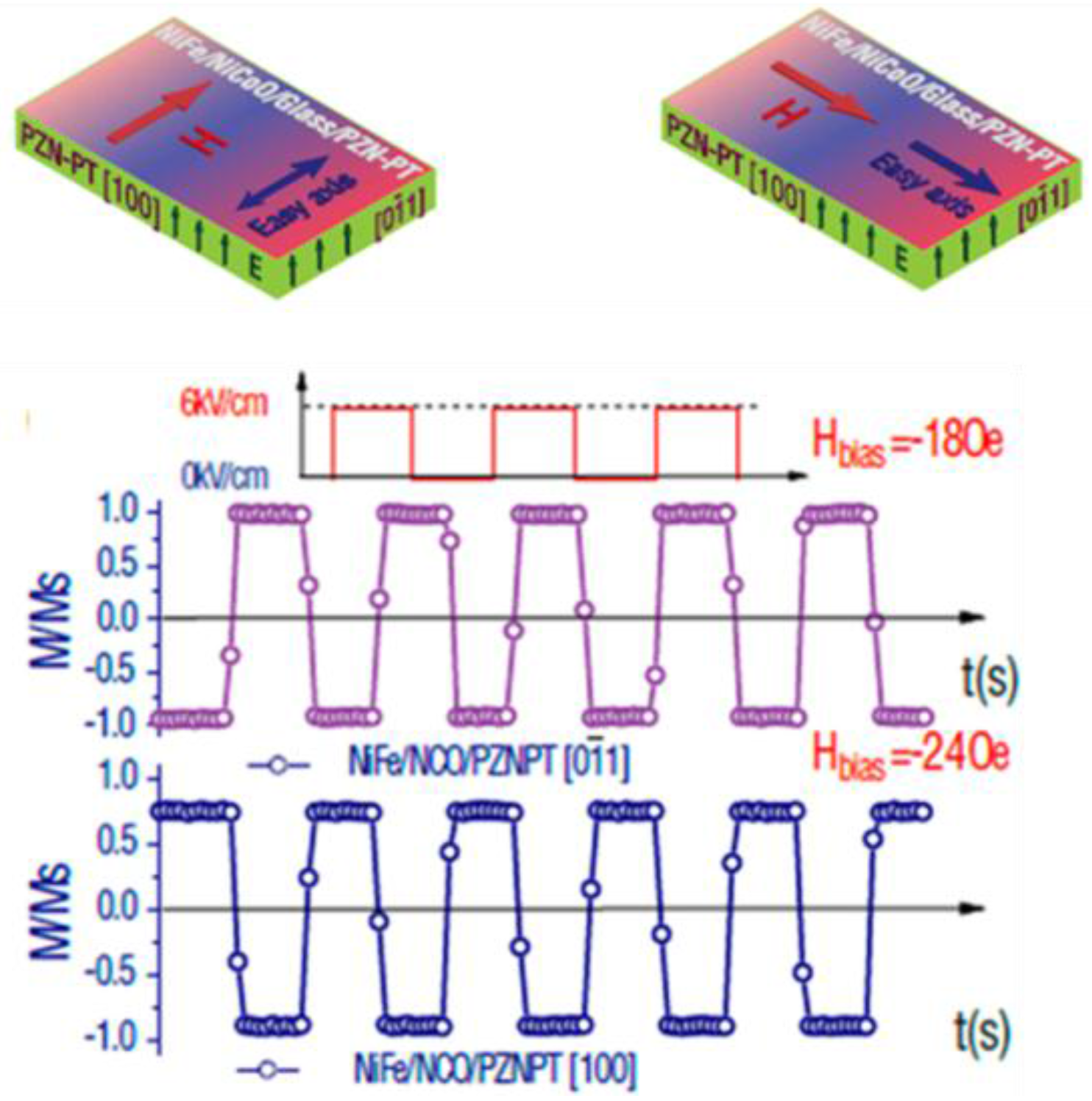
5.2. Devices Based on the CME Effect
5.2.1. Magnetoelectric Random Access Memory
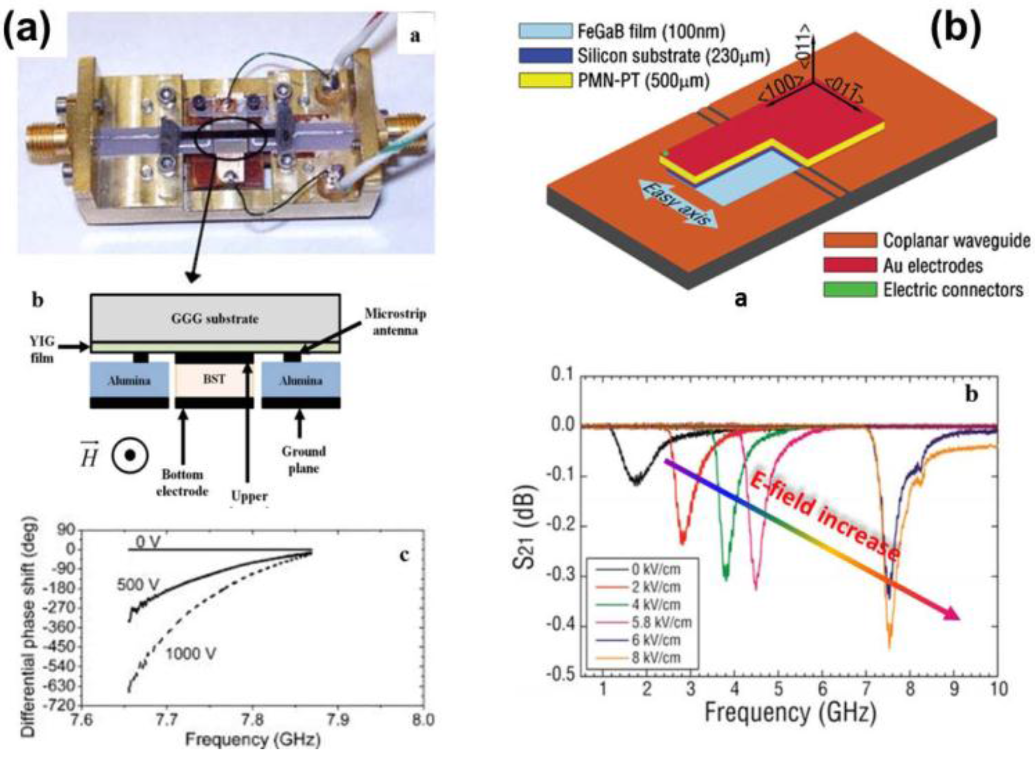
5.2.2. Phase Shifters
5.2.3. Resonators
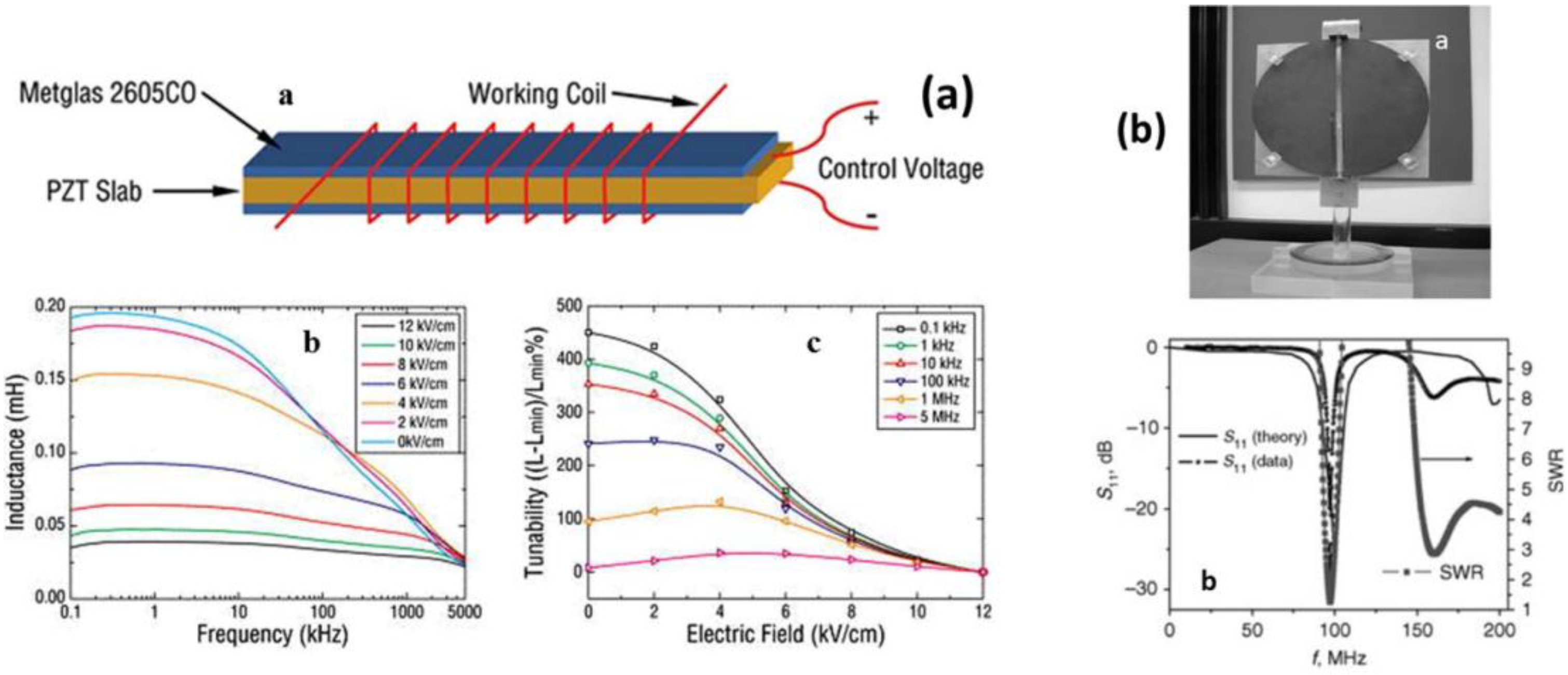
5.2.4. Inductors
5.2.5. ME Antenna
6. Summary
Acknowledgments
Conflicts of Interest
References
- Wang, Y.; Hu, J.; Lin, Y.; Nan, C.-W. Multiferroic magnetoelectric composite nanostructures. NPG Asia Mater. 2010, 2, 61–68. [Google Scholar] [CrossRef]
- Priya, S.; Islam, R.; Dong, S.; Viehland, D. Recent advancements in magnetoelectric particulate and laminate composites. J. Electroceram. 2007, 19, 149–166. [Google Scholar] [CrossRef]
- Nan, C.-W.; Bichurin, M.I.; Dong, S.; Viehland, D.; Srinivasan, G. Multiferroic magnetoelectric composites: Historical perspective, status, and future directions. J. Appl. Phys. 2008, 103, 031101. [Google Scholar] [CrossRef]
- Vaz, C.A.F.; Hoffman, J.; Ahn, C.H.; Ramesh, R. Magnetoelectric coupling effects in multiferroic complex oxide composite structures. Adv. Mater. 2010, 22, 2900–2918. [Google Scholar] [CrossRef] [PubMed]
- Ryu, J.; Priya, S.; Uchino, K.; Kim, H.-E. Magnetoelectric Effect in Composites of Magnetostrictive and Piezoelectric Materials. J. Electroceram. 2002, 8, 107–119. [Google Scholar] [CrossRef]
- Fang, Z.; Zhang, Q.; Datta, S. Ultra sensitive magnetic sensors integrating the giant magnetoelectric effect with advanced microelectronics. Ph.D. Thesis, Pennsylvania State University, University Park, PA, USA, December 2011. [Google Scholar]
- Cho, K.-H.; Priya, S. Direct and converse effect in magnetoelectric laminate composites. Appl. Phys. Lett. 2011, 98, 232904. [Google Scholar] [CrossRef]
- Newnham, R.E.; Skinner, D.P.; Cross, L.E. Connectivity and piezoelectric-pyroelectric composites. Mater. Res. Bull. 1978, 13, 525–536. [Google Scholar] [CrossRef]
- Nan, C.-W.; Jia, Q. Obtaining ultimate functionalities in nanocomposites: Design, control, and fabrication. MRS Bull. 2015, 40, 719–724. [Google Scholar] [CrossRef]
- Park, C.S.; Ryu, J.; Choi, J.J.; Park, D.S.; Ahn, C.W.; Priya, S. Giant Magnetoelectric Coefficient in 3–2 Nanocomposite Thick Films. Jpn. J. Appl. Phys. 2009, 48, 080204. [Google Scholar] [CrossRef]
- Gillette, S.M.; Fitchorov, T.; Obi, O.; Jiang, L.; Hao, H.; Wu, S.; Chen, Y.; Harris, V.G. Effects of intrinsic magnetostriction on tube-topology magnetoelectric sensors with high magnetic field sensitivity. J. Appl. Phys. 2014, 115, 17C734. [Google Scholar] [CrossRef]
- Yan, Y.; Priya, S. Multiferroic Magnetoelectric Composites/Hybrids. In Hybrid and Hierarchical Composite Materials; Kim, C.-S., Randow, C., Sano, T., Eds.; Springer International Publishing: Cham, Switzerland, 2015; pp. 95–160. [Google Scholar]
- Islam, R.; Rong, C.-B.; Liu, J.P.; Priya, S. Effect of gradient composite structure in cofired bilayer composites of Pb(Zr0.56Ti0.44)O3–Ni0.6Zn0.2Cu0.2Fe2O4 system on magnetoelectric coefficient. J. Mater. Sci. 2008, 43, 6337–6343. [Google Scholar] [CrossRef]
- Srinivasan, G.; DeVreugd, C.P.; Flattery, C.S.; Laletsin, V.M.; Paddubnaya, N. Magnetoelectric interactions in hot-pressed nickel zinc ferrite and lead zirconante titanate composites. Appl. Phys. Lett. 2004, 85, 2550–2552. [Google Scholar] [CrossRef]
- Jiang, Q.H.; Shen, Z.J.; Zhou, J.P.; Shi, Z.; Nan, C.-W. Magnetoelectric composites of nickel ferrite and lead zirconnate titanate prepared by spark plasma sintering. J. Eur. Ceram. Soc. 2007, 27, 279–284. [Google Scholar] [CrossRef]
- Islam, R.A.; Priya, S. Synthesis of high magnetoelectric coefficient composites using annealing and aging route. Int. J. Appl. Ceram. Tech. 2006, 3, 353–363. [Google Scholar] [CrossRef]
- Liu, R.; Zhao, Y.; Huang, R.; Zhao, Y.; Zhou, H. Multiferroic ferrite/perovskite oxide core/shell nanostructures. J. Mater. Chem. 2010, 20, 10665–10670. [Google Scholar] [CrossRef]
- Islam, R.A.; Bedekar, V.; Poudyal, N.; Liu, J.P.; Priya, S. Magnetoelectric properties of core-shell particulate nanocomposites. J. Appl. Phys. 2008, 104, 104111. [Google Scholar] [CrossRef]
- Shi, Z.; Nan, C.W.; Zhang, J.; Cai, N.; Li, J.-F. Magnetoelectric effect of Pb(Zr,Ti)O3 rod arrays in a (Tb,Dy)Fe2/epoxy medium. Appl. Phys. Lett. 2005, 87, 012503. [Google Scholar] [CrossRef]
- Lam, K.H.; Lo, C.Y.; Chan, H.L.W. Frequency response of magnetoelectric 1–3-type composites. J. Appl. Phys. 2010, 107, 093901. [Google Scholar] [CrossRef]
- Ma, J.; Shi, Z.; Nan, C.W. Magnetoelectric properties of composites of single Pb(Zr,Ti)O3 rods and Terfenol-D/Epoxy with a single-period of 1–3-type structure. Adv. Mater. 2007, 19, 2571–2573. [Google Scholar] [CrossRef]
- Islam, R.A.; Ni, Y.; Khachaturyan, A.G.; Priya, S. Giant magnetoelectric effect in sintered multilayered composite structures. J. Appl. Phys. 2008, 104, 044103. [Google Scholar] [CrossRef]
- Dong, S.; Zhai, J.; Li, J.; Viehland, D. Near-ideal magnetoelectricity in high-permeability magnetostrictive/piezofiber laminates with a (2–1) connectivity. Appl. Phys. Lett. 2006, 89, 252904. [Google Scholar] [CrossRef]
- Wang, Y.; Gray, D.; Berry, D.; Gao, J.; Li, M.; Li, J.; Viehland, D. An extremely low equivalent magnetic noise magnetoelectric sensor. Adv. Mater. 2011, 23, 4111–4114. [Google Scholar] [CrossRef] [PubMed]
- Mori, K.; Wuttig, M. Magnetoelectric coupling in Terfenol-D/polyvinylidenedifluoride composites. Appl. Phys. Lett. 2002, 81, 100–101. [Google Scholar] [CrossRef]
- Silva, M.; Reis, S.; Lehmann, C.S.; Martins, P.; Lanceros-Mendez, S.; Lasheras, A.; Gutiérrez, J.; Barandiarán, J.M. Optimization of the Magnetoelectric Response of Poly(vinylidene fluoride)/Epoxy/Vitrovac Laminates. ACS Appl. Mater. Inter. 2013, 5, 10912–10919. [Google Scholar] [CrossRef] [PubMed]
- Lawes, G.; Srinivasan, G. Introduction to magnetoelectric coupling and multiferroic films. J. Phys. D Appl. Phy. 2011, 44, 243001. [Google Scholar] [CrossRef]
- McDannald, A.; Staruch, M.; Sreenivasulu, G.; Cantoni, C.; Srinivasan, G.; Jain, M. Magnetoelectric coupling in solution derived 3–0 type PbZr0.52Ti0.48O3:xCoFe2O4 nanocomposite films. Appl. Phys. Lett. 2013, 102, 122905. [Google Scholar] [CrossRef]
- Zheng, H.; Wang, J.; Lofland, S.E.; Ma, Z.; Mohaddes-Ardabili, L.; Zhao, T.; Salamanca-Riba, L.; Shinde, S.R.; Ogale, S.B.; Bai, F.; et al. Multiferroic BaTiO3-CoFe2O4 nanostructures. Science 2004, 303, 661–663. [Google Scholar] [CrossRef] [PubMed]
- Aimon, N.M.; Kim, D.H.; Sun, X.; Ross, C.A. Multiferroic behavior of templated BiFeO3-CoFe2O4 self-assembled nanocomposites. ACS Appl. Mater. Interf. 2015, 7, 2263–2268. [Google Scholar] [CrossRef] [PubMed]
- Srinivasan, G. Layered multiferroic composites. In Composite Magnetoelectrics; Srinivasan, G., Priya, S., Sun, N.X., Eds.; Woodhead Publishing: Cambridge, UK, 2015; pp. 55–70. [Google Scholar]
- Zhou, Z.; Sun, N.X. Multiferroic nanostructures. In Composite Magnetoelectrics; Srinivasan, G., Priya, S., Sun, N.X., Eds.; Woodhead Publishing: Cambridge, UK, 2015; pp. 71–86. [Google Scholar]
- Lage, E.; Kirchhof, C.; Hrkac, V.; Kienle, L.; Jahns, R.; Knöchel, R.; Quandt, E.; Meyners, D. Exchange biasing of magnetoelectric composites. Nat. Mater. 2012, 11, 523–529. [Google Scholar] [CrossRef] [PubMed]
- Greve, H.; Woltermann, E.; Quenzer, H.-J.; Wagner, B.; Quandt, E. Giant magnetoelectric coefficients in (Fe90Co10)78Si12B10-AlN thin film composites. Appl. Phys. Lett. 2010, 96, 182501. [Google Scholar] [CrossRef]
- Nair, S.S.; Pookat, G.; Saravanan, V.; Anantharaman, M.R. Lead free heterogeneous multilayers with giant magneto electric coupling for microelectronics/microelectromechanical systems applications. J. Appl. Phys. 2013, 114, 064309. [Google Scholar] [CrossRef]
- Srinivasan, G.; Rasmussen, E.T.; Gallegos, J.; Srinivasan, R.; Bokhan, Y.I.; Laletin, V.M. Magnetoelectric bilayer and multilayer structures of magnetostrictive and piezoelectric oxides. Phys. Rev. B. 2001, 64, 214408. [Google Scholar] [CrossRef]
- Kambale, R.C.; Ryu, J.; Patil, D.R.; Chai, Y.S.; Kim, K.H.; Yoon, W.-H.; Jeong, D.-Y.; Park, D.-S.; Kim, J.-W.; Choi, J.-J.; et al. Colossal magnetoelectric response of PZT thick films on Ni substrates with a conductive LaNiO3 electrode. J. Phys. D Appl. Phy. 2013, 46, 092002. [Google Scholar] [CrossRef]
- Zhou, D.; Jian, G.; Zheng, Y.; Gong, S.; Shi, F. Electrophoretic deposition of BaTiO3/CoFe2O4 multiferroic composite films. Appl. Surf. Sci. 2011, 257, 7621–7626. [Google Scholar] [CrossRef]
- Palneedi, H.; Maurya, D.; Kim, G.-Y.; Priya, S.; Kang, S.-J.L.; Kim, K.-H.; Choi, S.-Y.; Ryu, J. Enhanced off-resonance magnetoelectric response in laser annealed PZT thick film grown on magnetostrictive amorphous metal substrate. Appl. Phys. Lett. 2015, 107, 012904. [Google Scholar] [CrossRef]
- Pan, D.A.; Bai, Y.; Chu, W.Y.; Qiao, L.J. Ni–PZT–Ni trilayered magnetoelectric composites synthesized by electro-deposition. J. Phys. Condens. Matter. 2008, 20, 025203. [Google Scholar] [CrossRef]
- Bi, K.; Wang, Y.G.; Wu, W.; Pan, D.A. The large magnetoelectric effect in Ni–lead zirconium titanate–Ni trilayers derived by electroless deposition. J. Phys. D Appl. Phy. 2010, 43, 132002. [Google Scholar] [CrossRef]
- Yu, H.; Zeng, M.; Wang, Y.; Wan, J.G.; Liu, J.-M. Magnetoelectric resonance-bandwidth broadening of Terfenol-D/epoxy-Pb(Zr,Ti)O3 bilayers in parallel and series connections. Appl. Phys. Lett. 2005, 86, 032508. [Google Scholar] [CrossRef]
- Park, C.-S.; Ahn, C.-W.; Ryu, J.; Yoon, W.-H.; Park, D.-S.; Kim, H.-E.; Priya, S. Design and characterization of broadband magnetoelectric sensor. J. Appl. Phys. 2009, 105, 094111. [Google Scholar] [CrossRef]
- Park, C.-S.; Priya, S. Broadband/wideband magnetoelectric response. Adv. Condens. Matter Phys. 2012, 2012, 323165. [Google Scholar] [CrossRef]
- Patil, D.R.; Kambale, R.C.; Chai, Y.; Yoon, W.-H.; Jeong, D.-Y.; Park, D.-S.; Kim, J.-W.; Choi, J.-J.; Ahn, C.-W.; Hahn, B.-D.; et al. Multiple broadband magnetoelectric response in thickness-controlled Ni/[011] Pb(Mg1/3Nb2/3)O3-Pb(Zr,Ti)O3 single crystal/Ni laminates. Appl. Phys. Lett. 2013, 103, 052907. [Google Scholar] [CrossRef]
- Patil, D.R.; Chai, Y.; Kambale, R.C.; Jeon, B.-G.; Yoo, K.; Ryu, J.; Yoon, W.-H.; Park, D.-S.; Jeong, D.-Y.; Lee, S.-G.; et al. Enhancement of resonant and non-resonant magnetoelectric coupling in multiferroic laminates with anisotropic piezoelectric properties. Appl. Phys. Lett. 2013, 102, 062909. [Google Scholar] [CrossRef]
- Kambale, R.C.; Yoon, W.-H.; Park, D.-S.; Choi, J.-J.; Ahn, C.-W.; Kim, J.-W.; Hahn, B.-D.; Jeong, D.-Y.; Lee, B.-C.; Chung, G.-S.; et al. Magnetoelectric properties and magnetomechanical energy harvesting from stray vibration and electromagnetic wave by Pb(Mg1/3Nb2/3)O3-Pb(Zr,Ti)O3 single crystal/Ni cantilever. J. Appl. Phys. 2013, 113, 204108. [Google Scholar] [CrossRef]
- Priya, S.; Yang, S.C.; Maurya, D.; Yan, Y. Recent advances in piezoelectric and magnetoelectric materials phenomena. In Composite Magnetoelectrics; Srinivasan, G., Priya, S., Sun, N.X., Eds.; Woodhead Publishing: Cambridge, UK, 2015; pp. 103–157. [Google Scholar]
- Yan, Y.; Cho, K.-H.; Maurya, D.; Kumar, A.; Kalinin, S.; Khachaturyan, A.; Priya, S. Giant energy density in [001]-textured Pb(Mg1/3Nb2/3)O3-PbZrO3-PbTiO3 piezoelectric ceramics. Appl. Phys. Lett. 2013, 102, 042903. [Google Scholar] [CrossRef] [Green Version]
- Wang, Y.; Zhao, X.; Jiao, J.; Zhang, Q.; Di, W.; Luo, H.; Leung, C.M.; Or, S.W. Lead-free magnetoelectric laminated composite of Mn-doped Na0.5Bi0.5TiO3–BaTiO3 single crystal and Tb0.3Dy0.7Fe1.92 alloy. J. Alloy Compd. 2010, 496, L4–L6. [Google Scholar] [CrossRef]
- Zhou, Y.; Maurya, D.; Yan, Y.; Srinivasan, G.; Quandt, E.; Priya, S. Self-biased magnetoelectric composites: An overview and future perspectives. Energy Harvest. Syst. 2016, 3, 1–42. [Google Scholar] [CrossRef]
- Mandal, S.K.; Sreenivasulu, G.; Petrov, V.M.; Srinivasan, G. Magnetization-graded multiferroic composite and magnetoelectric effects at zero bias. Phys. Rev. B. 2011, 84, 014432. [Google Scholar] [CrossRef]
- Raidongia, K.; Nag, A.; Sundaresan, A.; Rao, C.N.R. Multiferroic and magnetoelectric properties of core-shell CoFe2O4@BaTiO3 nanocomposites. Appl. Phys. Lett. 2010, 97, 062904. [Google Scholar] [CrossRef]
- Liu, M.; Li, X.; Imrane, H.; Chen, Y.; Goodrich, T.; Cai, Z.; Ziemer, K.S.; Huang, J.Y.; Sun, N.X. Synthesis of ordered arrays of multiferroic NiFe2O4-Pb(Zr0.52Ti0.48)O3 core-shell nanowires. Appl. Phys. Lett. 2007, 90, 152501. [Google Scholar] [CrossRef]
- Starr, J.D.; Andrew, J.S. Janus-type bi-phasic functional nanofibers. Chem. Comm. 2013, 49, 4151–4153. [Google Scholar] [CrossRef] [PubMed]
- Andrew, J.S.; Starr, J.D.; Budi, M.A.K. Prospects for nanostructured multiferroic composite materials. Scripta Mater. 2014, 74, 38–43. [Google Scholar] [CrossRef]
- Xie, S.; Ma, F.; Liu, Y.; Li, J. Multiferroic CoFe2O4-Pb(Zr0.52Ti0.48)O3 core-shell nanofibers and their magnetoelectric coupling. Nanoscale 2011, 3, 3152–3158. [Google Scholar] [CrossRef] [PubMed]
- Xie, S.H.; Li, J.Y.; Liu, Y.Y.; Lan, L.N.; Jin, G.; Zhou, Y.C. Electrospinning and multiferroic properties of NiFe2O4–Pb(Zr0.52Ti0.48)O3 composite nanofibers. J. Appl. Phys. 2008, 104, 024115. [Google Scholar] [CrossRef]
- Srinivasan, G. Magnetoelectric characterization techniques. In Composite Magnetoelectrics; Srinivasan, G., Priya, S., Sun, N.X., Eds.; Woodhead Publishing: Cambridge, UK, 2015; pp. 41–54. [Google Scholar]
- Zhou, Y.; Apo, D.J.; Sanghadasa, M.; Bichurin, M.; Petrov, V.M.; Priya, S. Magnetoelectric energy harvester. In Composite Magnetoelectrics; Srinivasan, G., Priya, S., Sun, N.X., Eds.; Woodhead Publishing: Cambridge, UK, 2015; pp. 161–207. [Google Scholar]
- Dong, S.; Zhai, J.; Xing, Z.; Li, J.; Viehland, D. Giant magnetoelectric effect (under a dc magnetic bias of 2 Oe) in laminate composites of FeBSiC alloy ribbons and Pb(Zn1∕3Nb2∕3)O3–7%PbTiO3 fibers. Appl. Phys. Lett. 2007, 91, 022915. [Google Scholar] [CrossRef]
- Park, C.-S.; Cho, K.-H.; Arat, M.A.; Evey, J.; Priya, S. High magnetic field sensitivity in Pb(Zr,Ti)O3–Pb(Mg1/3Nb2/3)O3 single crystal/Terfenol-D/Metglas magnetoelectric laminate composites. J. Appl. Phys. 2010, 107, 094109. [Google Scholar] [CrossRef]
- Ramana, M.V.; Reddy, N.R.; Sreenivasulu, G.; Kumar, K.V.S.; Murty, B.S.; Murthy, V.R.K. Enhanced mangnetoelectric voltage in multiferroic particulate Ni0.83Co0.15Cu0.02Fe1.9O4−δ/PbZr0.52Ti0.48O3 composites—dielectric, piezoelectric and magnetic properties. Curr. Appl. Phys. 2009, 9, 1134–1139. [Google Scholar] [CrossRef]
- Sreenivasulu, G.; Fetisov, L.Y.; Fetisov, Y.K.; Srinivasan, G. Piezoelectric single crystal langatate and ferromagnetic composites: Studies on low-frequency and resonance magnetoelectric effects. Appl. Phys. Lett. 2012, 100, 052901. [Google Scholar] [CrossRef]
- Chen, Y.; Gillette, S.M.; Fitchorov, T.; Jiang, L.; Hao, H.; Li, J.; Gao, X.; Geiler, A.; Vittoria, C.; Harris, V.G. Quasi-one-dimensional miniature multiferroic magnetic field sensor with high sensitivity at zero bias field. Appl. Phys. Lett. 2011, 99, 042505. [Google Scholar] [CrossRef]
- Zhang, N.; Fan, J.; Rong, X.; Cao, H.; Wei, J. Magnetoelectric effect in laminate composites of Tb1−xDyxFe2−y and Fe-doped BaTiO3. J. Appl. Phys. 2007, 101, 063907. [Google Scholar] [CrossRef]
- Islam, R.A.; Kim, H.; Priya, S.; Stephanou, H. Piezoelectric transformer based ultrahigh sensitivity magnetic field sensor. Appl. Phys. Lett. 2006, 89, 152908. [Google Scholar] [CrossRef]
- Feng, M.; Wang, J.-J.; Hu, J.-M.; Wang, J.; Ma, J.; Li, H.-B.; Shen, Y.; Lin, Y.-H.; Chen, L.-Q.; Nan, C.-W. Optimizing direct magnetoelectric coupling in Pb(Zr,Ti)O3/Ni multiferroic film heterostructures. Appl. Phys. Lett. 2015, 106, 072901. [Google Scholar] [CrossRef]
- Tahmasebi, K.; Barzegar, A.; Ding, J.; Herng, T.S.; Huang, A.; Shannigrahi, S. Magnetoelectric effect in Pb(Zr0.95Ti0.05)O3 and CoFe2O4 heteroepitaxial thin film composite. Mater. Des. 2011, 32, 2370–2373. [Google Scholar] [CrossRef]
- Martínez, R.; Kumar, A.; Palai, R.; Srinivasan, G.; Katiyar, R.S. Observation of strong magnetoelectric effects in Ba0.7Sr0.3TiO3/La0.7Sr0.3MnO3 thin film heterostructures. J. Appl. Phys. 2012, 111, 104104. [Google Scholar]
- Park, C.-S.; Khachaturyan, A.; Priya, S. Giant magnetoelectric coupling in laminate thin film structure grown on magnetostrictive substrate. Appl. Phys. Lett. 2012, 100, 192904. [Google Scholar] [CrossRef]
- Sun, N.X.; Srinivasan, G. Voltage control of magnetism in multiferroic heterostructures and devices. SPIN 2012, 2, 1240004. [Google Scholar] [CrossRef]
- Paluszek, M.; Avirovik, D.; Zhou, Y.; Kundu, S.; Chopra, A.; Montague, R.; Priya, S. Magnetoelectric composites for medical application. In Composite Magnetoelectrics; Srinivasan, G., Priya, S., Sun, N.X., Eds.; Woodhead Publishing: Cambridge, UK, 2015; pp. 297–327. [Google Scholar]
- Dong, S.; Zhai, J.; Bai, F.; Li, J.-F.; Viehland, D. Push-pull mode magnetostrictive /piezoelectric laminate composite with an enhanced magnetoelectric voltage coefficient. Appl. Phys. Lett. 2005, 87, 062502. [Google Scholar] [CrossRef]
- Gao, J.; Das, J.; Xing, Z.; Li, J.; Viehland, D. Comparison of noise floor and sensitivity for different magnetoelectric laminates. J. Appl. Phys. 2010, 108, 084509. [Google Scholar] [CrossRef]
- Li, M.; Wang, Z.; Wang, Y.; Li, J.; Viehland, D. Giant magnetoelectric effect in self-biased laminates under zero magnetic field. Appl. Phys. Lett. 2013, 102, 082404. [Google Scholar] [CrossRef]
- Wang, Y.; Hasanyan, D.; Li, M.; Gao, J.; Li, J.; Viehland, D. Equivalent magnetic noise in multi-push-pull configuration magnetoelectric composites: Model and experiment. IEEE Trans. Ultrason. Ferroelectr. Freq. Control. 2013, 60, 1227–1233. [Google Scholar] [CrossRef] [PubMed]
- Das, J.; Gao, J.; Xing, Z.; Li, J.F.; Viehland, D. Enhancement in the field sensitivity of magnetoelectric laminate heterostructures. Appl. Phys. Lett. 2009, 95, 092501. [Google Scholar] [CrossRef]
- Gao, J.; Gray, D.; Shen, Y.; Li, J.; Viehland, D. Enhanced dc magnetic field sensitivity by improved flux concentration in magnetoelectric laminates. Appl. Phys. Lett. 2011, 99, 153502. [Google Scholar] [CrossRef]
- Wang, Y.; Li, M.; Hasanyan, D.; Gao, J.; Li, J.; Viehland, D. Geometry-induced magnetoelectric effect enhancement and noise floor reduction in Metglas/piezofiber sensors. Appl. Phys. Lett. 2012, 101, 092905. [Google Scholar] [CrossRef]
- Li, M.; Berry, D.; Das, J.; Gray, D.; Li, J.; Viehland, D. Enhanced sensitivity and reduced noise floor in magnetoelectric laminate sensors by an improved lamination process. J. Amer. Ceram. Soc. 2011, 94, 3738–3741. [Google Scholar] [CrossRef]
- Wang, Y.J.; Gao, J.Q.; Li, M.H.; Shen, Y.; Hasanyan, D.; Li, J.F.; Viehland, D. A review on equivalent magnetic noise of magnetoelectric laminate sensors. Philos. Trans. R. Soc. London Ser. A 2014, 372. [Google Scholar] [CrossRef] [PubMed]
- Gao, J.; Wang, Y.; Li, M.; Shen, Y.; Li, J.; Viehland, D. Quasi-static (f<10−2 Hz) frequency response of magnetoelectric composites based magnetic sensor. Mater. Lett. 2012, 85, 84–87. [Google Scholar]
- Shen, Y.; Gao, J.; Shen, L.; Gray, D.; Li, J.; Finkel, P.; Viehland, D.; Zhuang, X.; Saez, S.; Dolabdjian, C. Analysis of the environmental magnetic noise rejection by using two simple magnetoelectric sensors. Sens. Actuators A Phys. 2011, 171, 63–68. [Google Scholar] [CrossRef]
- Fang, C.; Jiao, J.; Ma, J.; Lin, D.; Xu, H.; Zhao, X.; Luo, H. Significant reduction of equivalent magnetic noise by in-plane series connection in magnetoelectric Metglas/Mn-doped Pb(Mg1/3Nb2/3)O3-PbTiO3 laminate composites. J. Phys. D Appl. Phy. 2015, 48, 465002. [Google Scholar] [CrossRef]
- Stephan, M.; Robert, J.; Henry, G.; Eckhard, Q.; Reinhard, K.; Bernhard, W. MEMS magnetic field sensor based on magnetoelectric composites. J. Micromech. Microeng. 2012, 22, 065024. [Google Scholar]
- Zhao, P.; Zhao, Z.; Hunter, D.; Suchoski, R.; Gao, C.; Mathews, S.; Wuttig, M.; Takeuchi, I. Fabrication and characterization of all-thin-film magnetoelectric sensors. Appl. Phys. Lett. 2009, 94, 243507. [Google Scholar] [CrossRef]
- Lee, D.G.; Kim, S.M.; Yoo, Y.K.G.; Han, J.H.; Chun, D.W.; Kim, Y.-C.; Kim, J.; Hwang, K.S.; Kim, T.S.; Jo, W.W.; et al. Ultra-sensitive magnetoelectric microcantilever at a low frequency. Appl. Phys. Lett. 2012, 101, 182902. [Google Scholar]
- Ramsden, E. Hall-Effect Sensors: Theory and Applications; Newnes Publications: Burlington, NJ, USA, 2006; pp. 1–9. [Google Scholar]
- Leung, C.M.; Or, S.W.; Zhang, S.; Ho, S.L. Ring-type electric current sensor based on ring-shaped magnetoelectric laminate of epoxy-bonded Tb0.3Dy0.7Fe1.92 short-fiber/NdFeB magnet magnetostrictive composite and Pb(Zr, Ti)O3 piezoelectric ceramic. J. Appl. Phys. 2010, 107, 09D918. [Google Scholar] [CrossRef]
- Lu, C.; Li, P.; Wen, Y.; Yang, A.; Yang, C.; Wang, D.; He, W.; Zhang, J. Magnetoelectric composite Metglas/PZT-based current sensor. IEEE Trans. Magn. 2014, 50, 1–4. [Google Scholar] [CrossRef]
- Zhang, S.; Leung, C.M.; Kuang, W.; Or, S.W.; Ho, S.L. Concurrent operational modes and enhanced current sensitivity in heterostructure of magnetoelectric ring and piezoelectric transformer. J. Appl. Phys. 2013, 113, 17C733. [Google Scholar] [CrossRef]
- Yu, X.; Lou, G.; Chen, H.; Wen, C.; Lu, S. A slice-type magnetoelectric laminated current sensor. IEEE Sens. J. 2015, 15, 5839–5850. [Google Scholar] [CrossRef]
- Patil, D.R.; Zhou, Y.; Kang, J.-E.; Sharpes, N.; Jeong, D.-Y.; Kim, Y.-D.; Kim, K.H.; Priya, S.; Ryu, J. Anisotropic self-biased dual-phase low frequency magneto-mechano-electric energy harvesters with giant power densities. APL Mater. 2014, 2, 046102. [Google Scholar] [CrossRef]
- Ryu, J.; Kang, J.-E.; Zhou, Y.; Choi, S.-Y.; Yoon, W.-H.; Park, D.-S.; Choi, J.-J.; Hahn, B.-D.; Ahn, C.-W.; Kim, J.-W.; et al. Ubiquitous magneto-mechano-electric generator. Energy Environ. Sci. 2015, 8, 2402–2408. [Google Scholar] [CrossRef]
- Zhou, Y.; Apo, D.J.; Priya, S. Dual-phase self-biased magnetoelectric energy harvester. Appl. Phys. Lett. 2013, 103, 192909. [Google Scholar] [CrossRef]
- Liu, G.; Ci, P.; Dong, S. Energy harvesting from ambient low-frequency magnetic field using magneto-mechano-electric composite cantilever. Appl. Phys. Lett. 2014, 104, 032908. [Google Scholar] [CrossRef]
- Lasheras, A.; Gutiérrez, J.; Reis, S.; Sousa, D.; Silva, M.; Martins, P.; Lanceros-Mendez, S.; Barandiarán, J.M.; Shishkin, D.A.; Potapov, A.P. Energy harvesting device based on a metallic glass/PVDF magnetoelectric laminated composite. Smart Mater. Struct. 2015, 24, 065024. [Google Scholar] [CrossRef]
- Li, P.; Wen, Y.; Liu, P.; Li, X.; Jia, C. A magnetoelectric energy harvester and management circuit for wireless sensor network. Sens. Actuators A. Phys. 2010, 157, 100–106. [Google Scholar] [CrossRef]
- Han, J.; Hu, J.; Wang, S.X.; He, J. Magnetic energy harvesting properties of piezofiber bimorph/NdFeB composites. Appl. Phys. Lett. 2014, 104, 093901. [Google Scholar] [CrossRef]
- Onuta, T.-D.; Wang, Y.; Long, C.J.; Takeuchi, I. Energy harvesting properties of all-thin-film multiferroic cantilevers. Appl. Phys. Lett. 2011, 99, 203506. [Google Scholar] [CrossRef]
- Bian, L.; Wen, Y.; Li, P.; Gao, Q.; Zheng, M. Magnetoelectric transducer with high quality factor for wireless power receiving. Sens. Actuators A Phys. 2009, 150, 207–211. [Google Scholar] [CrossRef]
- Gao, J.; Hasanyan, D.; Shen, Y.; Wang, Y.; Li, J.; Viehland, D. Giant resonant magnetoelectric effect in bi-layered Metglas/Pb(Zr,Ti)O3 composites. J. Appl. Phys. 2012, 112, 104101. [Google Scholar] [CrossRef]
- Dong, S.; Zhai, J.; Li, J.F.; Viehland, D.; Priya, S. Multimodal system for harvesting magnetic and mechanical energy. Appl. Phys. Lett. 2008, 93, 103511. [Google Scholar] [CrossRef]
- Cho, K.-H.; Park, H.-Y.; Heo, J.S.; Priya, S. Structure-performance relationships for cantilever-type piezoelectric energy harvesters. J. Appl. Phys. 2014, 115, 204108. [Google Scholar] [CrossRef]
- Vopsaroiu, M.; Blackburn, J.; Muniz-Piniella, A.; Cain, M.G. Multiferroic magnetic recording read head technology for 1Tbit/in.2 and beyond. J. Appl. Phys. 2008, 103, 07F506. [Google Scholar] [CrossRef]
- Zhang, Y.; Li, Z.; Deng, C.; Ma, J.; Lin, Y.; Nan, C.-W. Demonstration of magnetoelectric read head of multiferroic heterostructures. Appl. Phys. Lett. 2008, 92, 152510. [Google Scholar] [CrossRef]
- Kargol, A.; Malkinski, L.; Caruntu, G. Biomedical applications of multiferroic nanoparticles. In Advanced Magnetic Materials; Malkinski, L., Ed.; InTech: Rijeka, Croatia, 2012; pp. 89–118. [Google Scholar]
- Guduru, R.; Liang, P.; Runowicz, C.; Nair, M.; Atluri, V.; Khizroev, S. Magneto-electric nanoparticles to enable field-controlled high-specificity drug delivery to eradicate ovarian cancer cells. Sci. Rep. 2013, 3, 2953. [Google Scholar] [CrossRef] [PubMed]
- Yue, K.; Guduru, R.; Hong, J.; Liang, P.; Nair, M.; Khizroev, S. Magneto-electric nano-particles for non-invasive brain stimulation. PLoS One 2012, 7, e44040. [Google Scholar] [CrossRef] [PubMed]
- Dobson, J. Remote control of cellular behaviour with magnetic nanoparticles. Nat. Nano 2008, 3, 139–143. [Google Scholar] [CrossRef] [PubMed]
- Huang, H.; Delikanli, S.; Zeng, H.; Ferkey, D.M.; Pralle, A. Remote control of ion channels and neurons through magnetic-field heating of nanoparticles. Nat. Nano. 2010, 5, 602–606. [Google Scholar] [CrossRef] [PubMed]
- Ashcroft, F.M. Ion Channels and Disease; Academic Press: San Diego, CA, USA, 2000; pp. 1–2. [Google Scholar]
- Vopson, M.M. Fundamentals of multiferroic materials and their possible applications. Crit. Rev. Solid State Mater. Sci. 2015, 40, 223–250. [Google Scholar] [CrossRef] [Green Version]
- Bibes, M.; Barthelemy, A. Multiferroics: Towards a magnetoelectric memory. Nat. Mater. 2008, 7, 425–426. [Google Scholar] [CrossRef] [PubMed]
- Heron, J.T.; Trassin, M.; Ashraf, K.; Gajek, M.; He, Q.; Yang, S.Y.; Nikonov, D.E.; Chu, Y.H.; Salahuddin, S.; Ramesh, R. Electric-field-induced magnetization reversal in a ferromagnet-multiferroic heterostructure. Phys. Rev. Lett. 2011, 107, 217202. [Google Scholar] [CrossRef] [PubMed]
- Xue, X.; Zhou, Z.; Peng, B.; Zhu, M.; Zhang, Y.; Ren, W.; Ren, T.; Yang, X.; Nan, T.; Sun, N.X.; et al. Electric field induced reversible 180° magnetization switching through tuning of interfacial exchange bias along magnetic easy-axis in multiferroic laminates. Sci. Rep. 2015, 5, 16480. [Google Scholar] [CrossRef] [PubMed]
- Liu, M.; Lou, J.; Li, S.; Sun, N.X. E-field control of exchange bias and deterministic magnetization switching in AFM/FM/FE multiferroic heterostructures. Adv. Funct. Mater. 2011, 21, 2593–2598. [Google Scholar] [CrossRef]
- White, J.F. Review of semiconductor microwave phase shifters. Proc. IEEE 1968, 56, 1924–1931. [Google Scholar] [CrossRef]
- Boyd, C.R. A 60 GHz dual-mode ferrite phase shifter. In Proceedings of the 1982 IEEE MTT-S International Microwave Symposium Digest, Dallas, TX, USA, 15–17 June 1982; pp. 257–259.
- Zhao, Z.; Wang, X.; Choi, K.; Lugo, C.; Hunt, A.T. Ferroelectric Phase Shifters at 20 and 30 GHz. IEEE Trans. Microw. Theory Tech. 2007, 55, 430–437. [Google Scholar] [CrossRef]
- Ustinov, A.B.; Srinivasan, G.; Kalinikos, B.A. Ferrite-ferroelectric hybrid wave phase shifters. Appl. Phys. Lett. 2007, 90, 031913. [Google Scholar] [CrossRef]
- Tatarenko, A.S.; Srinivasan, G.; Bichurin, M.I. Magnetoelectric microwave phase shifter. Appl. Phys. Lett. 2006, 88, 183507. [Google Scholar] [CrossRef]
- Tatarenko, A.S.; Srinivasan, G. A strain engineered voltage tunable millimeter-wave ferrite phase shifter. Microwave Opt. Technol. Lett. 2011, 53, 261–264. [Google Scholar] [CrossRef]
- Kittel, C. On the theory of ferromagnetic resonance absorption. Phys. Rev. 1948, 73, 155–161. [Google Scholar] [CrossRef]
- Fetisov, Y.K.; Srinivasan, G. Electric field tuning characteristics of a ferrite-piezoelectric microwave resonator. Appl. Phys. Lett. 2006, 88, 143503. [Google Scholar] [CrossRef]
- Li, N.; Liu, M.; Zhou, Z.; Sun, N.X.; Murthy, D.V.B.; Srinivasan, G.; Klein, T.M.; Petrov, V.M.; Gupta, A. Electrostatic tuning of ferromagnetic resonance and magnetoelectric interactions in ferrite-piezoelectric heterostructures grown by chemical vapor deposition. Appl. Phys. Lett. 2011, 99, 192502. [Google Scholar] [CrossRef]
- Srinivasan, G. Microwave and millimeter-wave multiferroic devices. In Composite Magnetoelectrics; Srinivasan, G., Priya, S., Sun, N.X., Eds.; Woodhead Publishing: Cambridge, UK, 2015; pp. 241–264. [Google Scholar]
- Wang, S.G.; Yoon, S.D.; Vittoria, C. Microwave and magnetic properties of double-sided hexaferrite films on (111) magnesium oxide substrates. J. Appl. Phys. 2002, 92, 6728–6732. [Google Scholar] [CrossRef]
- Ustinov, A.B.; Tatarenko, A.S.; Srinivasan, G.; Balbashov, A.M. Al substituted Ba-hexaferrite single-crystal films for millimeter-wave devices. J. Appl. Phys. 2009, 105, 023908. [Google Scholar] [CrossRef]
- Tatarenko, A.S.; Murthy, D.V.B.; Srinivasan, G. Hexagonal ferrite-piezoelectric composites for dual magnetic and electric field tunable 8–25 GHz microstripline resonators and phase shifters. Microw. Opt. Technol. Lett. 2012, 54, 1215–1218. [Google Scholar] [CrossRef]
- Lou, J.; Reed, D.; Pettiford, C.; Liu, M.; Han, P.; Dong, S.; Sun, N.X. Giant microwave tunability in FeGaB/lead magnesium niobate-lead titanate multiferroic composites. Appl. Phys. Lett. 2008, 92, 262502. [Google Scholar] [CrossRef]
- Lou, J.; Liu, M.; Reed, D.; Ren, Y.; Sun, N.X. Giant electric field tuning of magnetism in novel multiferroic FeGaB/Lead Zinc Niobate–Lead Titanate (PZN-PT) Heterostructures. Adv. Mater. 2009, 21, 4711–4715. [Google Scholar] [CrossRef]
- Fang, X.; Zhang, N.; Wang, Z.L. Converse magnetoelectric effects on heterotype electrostrain-piezopermeability composites. Appl. Phys. Lett. 2008, 93, 102503. [Google Scholar] [CrossRef]
- Lou, J.; Reed, D.; Liu, M.; Sun, N.X. Electrostatically tunable magnetoelectric inductors with large inductance tenability. Appl. Phys. Lett. 2009, 94, 112508. [Google Scholar] [CrossRef]
- Hwaider, L.; Jing, L.; Yuan, G.; Hasegawa, R.; Ming, L.; Howe, B.; Jones, J.; Brown, G.; Sun, N.X. Voltage tunable magnetoelectric inductors with improved operational frequency and quality factor for power electronics. IEEE Trans. Magn. 2015, 51, 1–5. [Google Scholar] [CrossRef]
- Mandal, M.; Duttagupta, S.P.; Palkar, V.R. Study of multiferroic Bi0.7Dy0.3FeO3 based tunable ring inductor. J. Phys. D Appl. Phy. 2013, 46, 325001. [Google Scholar] [CrossRef]
- Garg, R. Microstrip Antenna Design Handbook; Artech House: Boston, MA, USA, 2001. [Google Scholar]
- Kim, D. Planar magneto-dielectric metasubstrate for miniaturization of a microstrip patch antenna. Microw. Opt. Technol. Lett. 2012, 54, 2871–2874. [Google Scholar] [CrossRef]
- Petrov, R.V.; Tatarenko, A.S.; Pandey, S.; Srinivasan, G.; Mantese, J.V.; Azadegan, R. Miniature antenna based on magnetoelectric composites. Electron. Lett. 2008, 44, 506–508. [Google Scholar] [CrossRef]
- Bae, S.; Hong, Y.K.; Lee, J.J.; Jalli, J.; Abo, G.S.; Lyle, A.; Seong, W.M.; Kum, J.S. Low loss Z-type barium ferrite (Co2Z) for terrestrial digital multimedia broadcasting antenna application. J. Appl. Phys. 2009, 105, 07A515. [Google Scholar] [CrossRef]
- Bae, S.; Hong, Y.K.; Lee, J.J.; Abo, G.S.; Jalli, J.; Park, J.H.; Seong, W.M.; Kum, J.S.; Ahn, W.K.; Park, S.H. Miniaturized broadband ferrite T-DMB antenna for mobile-phone applications. IEEE Trans. Magn. 2010, 46, 2361–2364. [Google Scholar] [CrossRef]
- Lee, J.; Hong, Y.-K.; Lee, W.; Abo, G.S.; Park, J.; Neveu, N.; Seong, W.-M.; Park, S.-H.; Ahn, W.-K. Soft M-type hexaferrite for very high frequency miniature antenna applications. J. Appl. Phys. 2012, 111, 07A520. [Google Scholar] [CrossRef]


| Piezoelectric Phase | Magnetostrictive Phase |
|---|---|
| Lead-based: | Metals: |
| Pb(Zr,Ti)O3 (PZT) | Fe, Co, Ni |
| Pb(Mg1/3Nb2/3)O3-PbTiO3 (PMN-PT) | Alloys: |
| Pb(Zn1/3Nb2/3)O3-PbTiO3 (PZN-PT) | FeNi-based |
| Pb(Mg1/3Nb2/3)y (ZrxTi1−x)1−yO3 (PMN–PZT) | FeCo-based |
| Pb(In1/2Nb1/2)O3-Pb(Mg1/3Nb2/3)O3-PbTiO3 (PIN-PMN-PT) | CoNi-based |
| Lead-free: | Ni2MnGa |
| BaTiO3 (BTO)-based | Permendur (FeCoV) |
| (K0.5Na0.5)NbO3 (KNN)-based | Galfenol (FeGa), FeGaB |
| Na0.5Bi0.5TiO3 (NBT)-based | Samfenol (SmFe2) |
| Others: | Terfenol-D (Tb1-xDyxFe2) |
| AlN | Fe-based metallic glasses (FeBSi, FeBSiC, FeCoB, FeCoSi, FeCoSiB, FeCuNbSiB) |
| ZnO | |
| (Sr, Ba)Nb2O5 | Ceramics: |
| Ba1-xSrxTiO3 (BSTO) | Fe3O4 |
| Bi1-xSrxTiO3 (BST) | Zn0.1Fe2.9O4 (ZFO) |
| La3Ga5.5SiO14 (LGS) | LaxSryMnO3 (LSMO) |
| La3Ga5.5Ta0.5O14 (LGT) | LaxCayMnO3 (LCMO) |
| Polyurethane (PU) | Ferrites or doped Ferrites (e.g., NiFe2O4 (NFO), CoFe2O4 (CFO), Li ferrite, Cu ferrite, Mn ferrite) |
| Polyvinylidene difluoride (PVDF) |
| ME Coupling | Physical Mechanism | ME Devices |
|---|---|---|
| Direct ME coupling | H control of electric polarization | Magnetic sensors, current sensors, transformers, gyrators, energy harvesters |
| Converse ME coupling | E control of magnetization switching | Spintronics, including random access memories, tunnel junctions |
| E control of permeability μ | Voltage tunable inductors, tunable band-pass filters, phase shifters | |
| E control of spin wave | Voltage tunable filters, tunable resonators, phase shifters |
© 2016 by the authors; licensee MDPI, Basel, Switzerland. This article is an open access article distributed under the terms and conditions of the Creative Commons by Attribution (CC-BY) license (http://creativecommons.org/licenses/by/4.0/).
Share and Cite
Palneedi, H.; Annapureddy, V.; Priya, S.; Ryu, J. Status and Perspectives of Multiferroic Magnetoelectric Composite Materials and Applications. Actuators 2016, 5, 9. https://doi.org/10.3390/act5010009
Palneedi H, Annapureddy V, Priya S, Ryu J. Status and Perspectives of Multiferroic Magnetoelectric Composite Materials and Applications. Actuators. 2016; 5(1):9. https://doi.org/10.3390/act5010009
Chicago/Turabian StylePalneedi, Haribabu, Venkateswarlu Annapureddy, Shashank Priya, and Jungho Ryu. 2016. "Status and Perspectives of Multiferroic Magnetoelectric Composite Materials and Applications" Actuators 5, no. 1: 9. https://doi.org/10.3390/act5010009