Article

Ferroelectric KNNT Fibers by Thermoplastic Extrusion Process: Microstructure and Electromechanical Characterization

1
Empa - Swiss Federal Laboratories for Materials Science and Technology, High Performance Ceramics, Überlandstrasse 129, CH-8600 Dübendorf, Switzerland
2
Changwon National University, Gyeong-Nam 641-773, South Korea
*
Authors to whom correspondence should be addressed.
These authors contributed equally to this work.
Actuators 2015, 4(2), 99-113; https://doi.org/10.3390/act4020099
Submission received: 20 March 2015 / Revised: 30 April 2015 / Accepted: 5 May 2015 / Published: 8 May 2015
(This article belongs to the Special Issue Feature Papers)

Abstract

:
B-site substitution in KNN with tantalum results in a higher d33 and dielectric constant. This higher value makes KNNT interesting for lead-free actuator applications. KNNT fibers with diameters of 300 and 500 μm have been extruded and sintered at 1200 °C in a KNNT-enriched atmosphere. Subsequently, the influence of fiber diameter on the microstructure (porosity and grain size) was investigated. The measurements revealed that with decreasing fiber diameter, the porosity increases, whereas the grain size decreases. The influence of these microstructural differences on the piezoelectric properties was evaluated using a novel characterization procedure for single fibers. The larger diameter fibers show an increase in the electromechanical properties measured, i.e., d33, tanδ, Pr, Ec and the free longitudinal fiber displacement, when compared to smaller diameter fibers. The lower alkali losses result in a larger grain size, a higher density during sintering and lead to higher electromechanical properties.

1. Introduction

Potassium sodium niobate is an environmentally-friendly alternative to lead-based piezoelectric ceramics and could eventually play a comparable role as lead zirconate titanate (PZT) in certain electronic applications in the future, with the added advantage of being bio-compatible [1,2,3]. The inducing of structural instabilities in a material by doping or substitution can lead to the enhancement of its electromechanical properties, which may be induced by compositional instability (morphotropic phase boundary (MPB)), thermal instability (polymorphic phase transition (PPT)), stress fields or external electric fields. The major insight from the work of Saito et al. was to highlight that the modification of the PPT with the use of dopants (e.g., Ta and Sb) [4] led to superior piezoelectric properties at room temperature, which appeared to be caused by the proximity of the temperature-induced PPT between tetragonal and orthorhombic phases at room temperature [5,6,7]. Tantalum as a dopant in KNN is known to hinder abnormal grain growth and to decrease both the Tc and the orthorhombic-tetragonal phase transition temperatures [8]. The properties making Ta substitution interesting for actuator applications are the enhancement of the dielectric and piezoelectric properties [9]. It also has a similar valance, ionic radius and similar electro-negativity to niobium (Ta, 1.5; Nb, 1.6) [10]. These properties make Ta an ideal candidate to act as a B-site substituent in KNN, as shown by Lee et al., who produced (K0.47Na0.545)(Nb0.55Ta0.45)O3 (KNNT) powder. In the Lee et al. KNNT study, the introduction of A-site non-stoichiometry (excess Na ion) was found to affect the MPB, which led to a rise in d33 [11].
The concept of smart composite materials with integrated fibers for sensing and actuation is still an essential spur that drives the development of piezoelectric ceramic fibers. Piezoelectric rods embedded in passive polymer matrix exhibit superior properties for ultrasound transduction over bulk piezoelectric ceramics due to lower acoustic impedance, higher coupling coefficient, reduced lateral coupling and higher flexibility [12]. The so-called 1-3 composites can be used for sonar, hydrophones, energy harvesting systems or medical diagnostic applications [13]. Another application includes micro-transformers, where according to the high surface-to-volume ratio, better self-cooling can be achieved. The piezoelectric transformer (PT) technology is a viable alternative to magnetic transformers in various applications, e.g., power supplies that employ PT rather than the classical magnetic transformers, resulting in smaller-sized power supplies [14]. The advantage gained with the use of the thermoplastic extrusion method is the ability to easily produce micro-scale devices with complex geometry [15].
In this study, KNNT fibers with a diameter between 300 µm and 500 µm were produced using a thermoplastic processing technique. The influence of fiber diameter on the microstructure properties (porosity, grain size, elemental stoichiometry, etc.) and the small and large signal electromechanical properties, such as piezoelectric charge coefficient (d33), polarization evolution (P-E) loop and strain evolution (S-E) loop, were investigated.

2. Experimental Section

(K0.47Na0.545)(Nb0.55Ta0.45)O3 (KNNT)-based green fibers were produced by mixing 54 vol% of KNNT powder (supplied by Changwon National University) with a polyolefin thermoplastic binder. The KNNT powder was prepared by a solid state process using raw powders of Na2CO3 (99.95%), K2CO3 (99.995%), Nb2O5 (99.9%) and Ta2O5 (99%). Hygroscopic Na2CO3 and K2CO3 were dried at 200 °C for at least 12 h to remove moisture absorbed in the raw powders. The raw materials were weighed in a glove box, keeping the moisture minimal. In the next step, the powder mixture was milled with yttria-stabilized zirconia balls in anhydrous alcohol for 24 h. After drying at 90 °C in a dry oven, the powders were calcined at 850 °C for 4 h in air with an intermediate ball milling and drying process, in order to produce powders of a uniform particle size. The powder processing is described in more detail in Lee et al. [11].
The powder density was measured by a helium pycnometer (Micromeritics, AccuPyc 1330). Laser diffraction (LS 230, Beckman Coulter, Brea, CA, USA) was used to establish the particle size distribution, and the specific surface area was determined by BET (Beckman-Coulter SA3100, Beckman-Coulter, Brea, CA, USA).
A low shear mixing method involved mixing of ceramic powder, a dispersant (Hypermer KD1, Uniqema (Croda International plc), Snaith, UK), a polyethylene oxide (PEO) (Polyox WSR301, Dow Chemicals, Midland, MI, USA) thermoplastic binder and toluene as a solvent, for one hour, just under the boiling point of the solvent. The dispersant content was fixed to a weight ratio of 1:0.3 against the KNN powder. The mixture was dried for 24 h at 60 °C, and the feedstock was collected for extrusion. The fully-dried feedstock was inspected by weight loss analysis. Green fibers were obtained by extruding the feedstock vertically with a capillary rheometer (RH7 Flowmaster, Rosand Precision Ltd., Stourbridge, UK) through a 300- and 500-µm die, at 106 °C and a shear rate of 500 s−1, with an adapter to reduce the diameter of the cylinder from 24 mm–4 mm. More details about the fiber production can be found in Lusiola et al. [16].
Debinding and sintering of the green fibers occurred on a Pt-coated zirconia substrate with v-shaped grooves, closed in an alumina crucible and sealed with alumina powder, where four 5 cm-long fibers were placed. In order to reduce the material volatilization during sintering of KNNT fibers, 1 g of KNNT powder was placed on the inside of the alumina crucible lid, creating a KNNT-rich atmosphere. The KNNT fibers were sintered at 1200 °C for 4 h [11].
The sintered fibers were characterized in terms of microstructure and phase composition. Porosity and grain size were determined on polished and thermally-etched fibers, respectively. For the thermal etching, polished fibers, embedded in a polymer matrix, were thermal heat treated at 1100 °C for 15 min. The porosity was investigated using a scanning electron microscope (SEM, Vega Plus 5136 MM, Tescan, Brno, Czech) and image analysis (Digital Micrograph 3.10.0, Gatan Inc., Pleasanton, CA, USA). For the grain size determination, FESEM (Tescan CZ/MIRA I LMH, Brno, Czech) and image analysis (ImageJ software, National Institute of Health, Bethesda, MD, USA) were used.
Phase analysis was performed using X-ray diffraction (XRD; X’Pert Pro MPD, PANalytical, Almelo, Netherlands) on crushed fibers, to have information about the average chemical phase composition. To identify the composition, the peaks between 2θ 22° and 23° and between 45° and 47° were selected for further analysis.
The ferroelectric behavior of single fibers was measured with a novel piece of equipment (FerroFib) developed from a collaboration between Empa and aixACCT System GmbH. A sketch of the latter’s instrument is shown in Figure 1, while the sample holder is reported by Belloli et al. [17]. The sintered fibers were cut to a length of ~2.5 mm and glued vertically onto a PMMA disc with Ag epoxy paste (Electrodag 5915, Acheson Colloids Co. (Henkel), Düsseldorf, Germany), with Ag epoxy paste used for the top electrode on the free end of the fiber. The bottom part of the disc was connected with a metallic electrode, which was used as the contact between the fiber and the FerroFib, as shown in Figure 1. A full description of sample fabrication is also described in detail in [18,19]. The fibers were poled for 5 min at room temperature under an applied electric field starting at 3.5 kV/mm and increasing at 0.5 kV/mm intervals until electrical breakdown.
P-E and S-E loops as a function of the applied electric field were recorded at 0.1 and 1 Hz. The small signal properties (d33) were measured at 10 and 100 Hz. The reported results for the large signal response (i.e., S-E and P-E loops) and the small signal response (i.e., d33, tanδ and er) are the averages of five fibers with the standard deviation calculated from these.
Figure 1. Sketch of the FerroFib: (a) equipment, (b) sample set-up.
Actuators 04 00099 g001

3. Results and Discussion

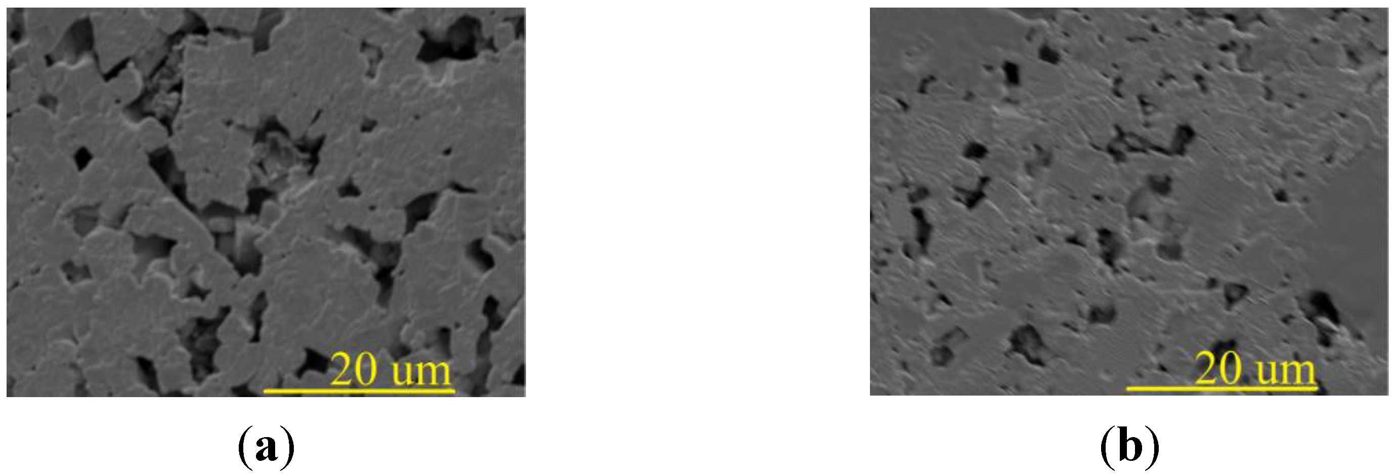
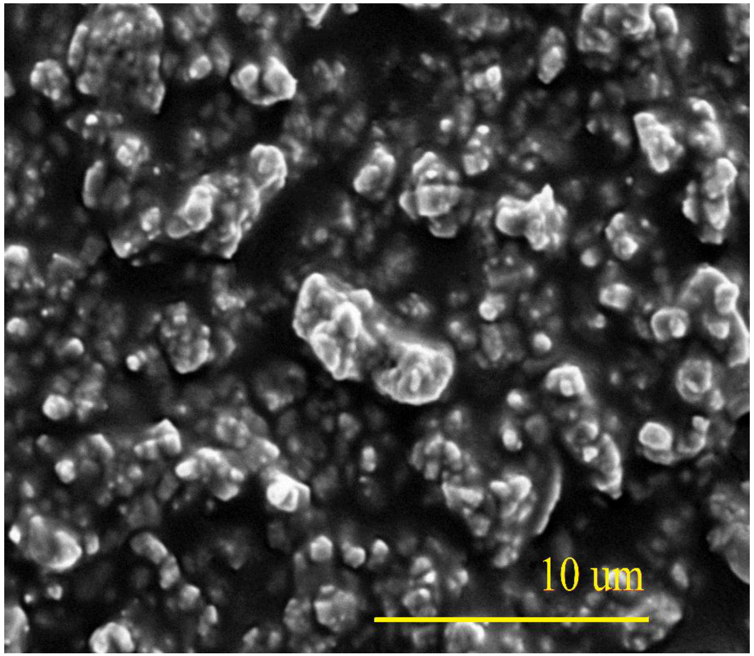
3.1. Microstructure and Phase Investigation

Table 1 shows the measured KNNT powder characteristics, while Figure 2 shows the SEM trace of the powder.
Table 1. KNNT powder properties.
Powder Characteristics
Density5.68 g/cm3
Specific Surface Area0.786 m2/g
Particle Sized10 (µm)d50 (µm)d90 (µm)
0.1311.884.438
Figure 2. The SEM scan of the KNNT powder.
Actuators 04 00099 g002
Ferroelectric properties are highly influenced by the material microstructure, such as grain size, porosity, chemical and phase composition. In Table 2, the microstructure characterization of the 300-µm and 500-µm KNNT fibers is reported. Optimal ferroelectric properties are exhibited by materials with a large grain size and low porosity, which applies to PZT [19], barium titanate [20,21], KNN [22,23], etc. The porosity in general for these samples was extremely high, which is due to the ongoing research and development of the thermoplastic sintering procedure, which requires optimizing (Table 2). The larger porosity displayed by the 300-µm fiber would be expected to affect the electromechanical performance. Comparing the grain size results with earlier studied bulk samples [24], the grain size of the fibers is slightly higher than bulk disc samples (bulk grain size 1.26 μm).
Table 2. The porosity characterization of 300-µm and 500-µm KNNT fibers.
300-µm Fibers500-µm Fibers
Porosity (%)36.9 ± 6.827.6 ± 4.7
Grain Size (µm)1.27 ± 0.011.41 ± 0.01
Garino et al. studied the effect of restricted sintering of ZnO films bonded to a rigid substrate and compared it to freely sintered ZnO films. Sintering without a substrate resulted in isotropic film shrinkage of 23%, compared to film shrinkage of 13% during constrained sintering [25,26], and to some degree, constraint sintering may contribute to the high level of porosity observed with the KNNT samples. This may be related to the slight pinning that occurred with the fibers on the Pt-coated zirconia substrates. In ferroelectric materials, the grain size is known to affect the relative permittivity of the material with maximum properties reported at 0.8–1-µm grain sizes. A smaller grain size results in an increase in internal stresses and an increase in εr [27]. Small grains reduce the piezoelectric properties; due to the high concentration of grain boundary interfaces, domain formation is hindered below a critical grain size (~1 µm) [28]. These facts point to the importance of achieving the right grain sizes. The grain growth starts in the intermediate sintering stage and is accelerated when a few pores remain [18]. The grain sizes achieved with the 300-µm and 500-µm fibers (Figure 3) suggest a near ideal grain size was achieved in both instances, though the variation in both suggests that the fiber diameter has a large influence on the grain size, with a larger diameter producing larger grains.
Figure 3. SEM scan showing the porosity and grain size of KNNT fibers with a diameter of (a) 300 µm after sintering and (b) 500 µm after sintering.
Actuators 04 00099 g003
Figure 4 shows the perovskite XRD pattern of the KNNT powder, as well as the 300-µm and 500-µm fibers, where in order to identify the phase composition, the (100) and (200) planes were selected due to the presence of two distinct reflections at each plane in the pure KNN powder: (101), (010), (002)O and (200)T [10].
Figure 4. X-ray diffraction patterns of KNNT powder and fibers with the inset of the XRD pattern between 21° and 24° and between 43° and 46°, as well as pure KNN powder. Actuators 04 00099 i001, extra phases, K2Nb8O21 and K3NbO4.
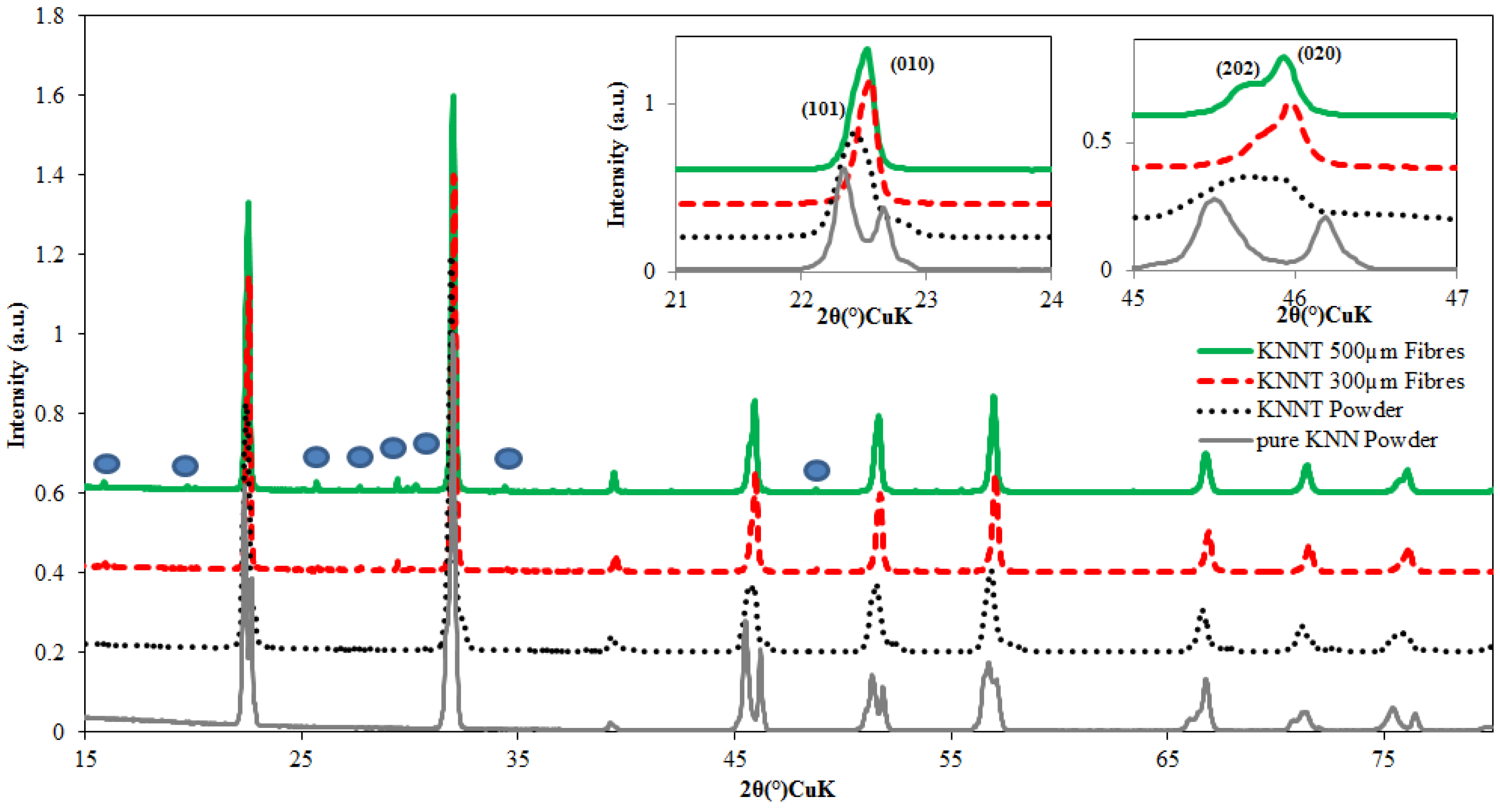
Actuators 04 00099 g004
As shown in Figure 4, all of the sintered fiber samples presented a tetragonal structure, which is quite different from pure KNN ceramics that possess an orthorhombic structure. Due to Ta5+ substitution, the peaks are shifted downfield due to the smaller radius of Ta5+. The XRD pattern exhibited a orthorhombic-tetragonal two-phase coexistence structure, due to the disappearance of the splitting of the (010) peak (Figure 4, inset), which revealed the increase of the tetragonal phase of the ceramic fiber samples with the substitution of Nb5+ by Ta5+ [10,24,29,30]. The intensity of the (202) peak varies slightly between the 300-µm and 500-µm fibers, with this peak having a higher intensity with the 500-µm fiber when compared to the 300-µm fiber, suggesting more phase coexistence present in the 500-µm fiber. The slight shift of the (010) downfield seen with the 300-µm relative to the similar (010) peak for the 500-µm fiber may indicate a change in the A-site stoichiometry, due to a decrease in unit cell volume [31,32]. The XRD pattern difference between the fibers is further evidence that the diameter of the fibers has an effect on the eventual composition of the sintered fibers. The additional phases in the XRD trace of the KNNT fibers may be K2Nb8O21 and K3NbO4, which have a tetragonal tungsten-bronze (TTB) structure [33]. The secondary phases appear to be more prevalent with the 500-µm fibers than the 300-µm fibers. Secondary phases are known to be a hindrance to a material’s electromechanical behavior, as their presence interferes with the perovskite structure.
An SEM/EDX investigation was carried out on the fibers (Table 3), and the result suggests that the smaller diameter/higher surface area of the 300-µm fiber allows higher alkali-loss (K ions), which occurred despite providing a KNNT-rich atmosphere within the sealed alumina reaction vessel: a result that is confirmed by the slight down shift to lower 2θ angles in the XRD peaks of the 300-µm fiber.
Table 3. The SEM EDX taken from a cross-section of the 300-µm and 500-µm KNNT fibers.
Element300-µm Fibers500-µm Fibers
wt%at%wt%at%
K5.065.976.628.48
Na5.4110.855.0410.98
Nb22.2911.062412.95
Ta46.311.846.912.99
O20.9360.3217.4354.6
Wang et al. found that the volatilization of alkali ions mainly occurred at moderate temperatures (600 °C) before the crystallization of the KNN perovskite phase, with the loss of Na ions being more significant than K ions during the thermal treatment [34]; this suggests that using the sealed KNNT atmosphere reduced the incidence of Na ion volatilization, but with a higher surface area-to-volume ratio, the effect of the KNNT atmosphere was reduced with respect to the 300-µm fibers at the higher sintering temperatures. The higher porosity observed in the 300-µm fibers may also manifest itself in the higher K ion loss (loss of material) when compared to the 500-µm fibers. Poor stoichiometry leads to a change in porosity and grain size and deterioration in the electrical properties of piezoelectric ceramics, which may be induced during ceramic processing [35].

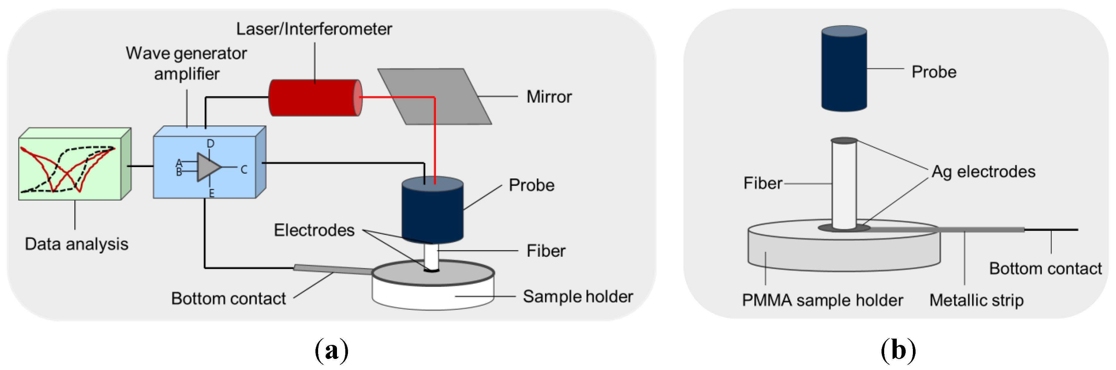
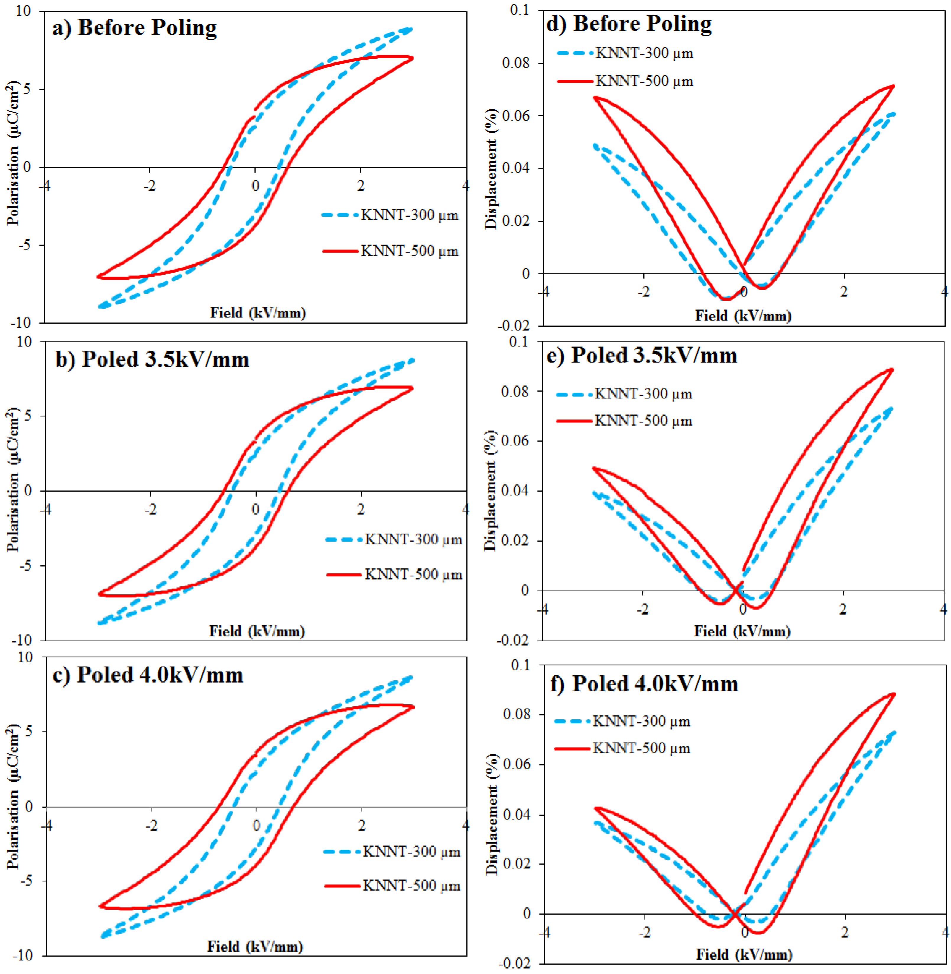
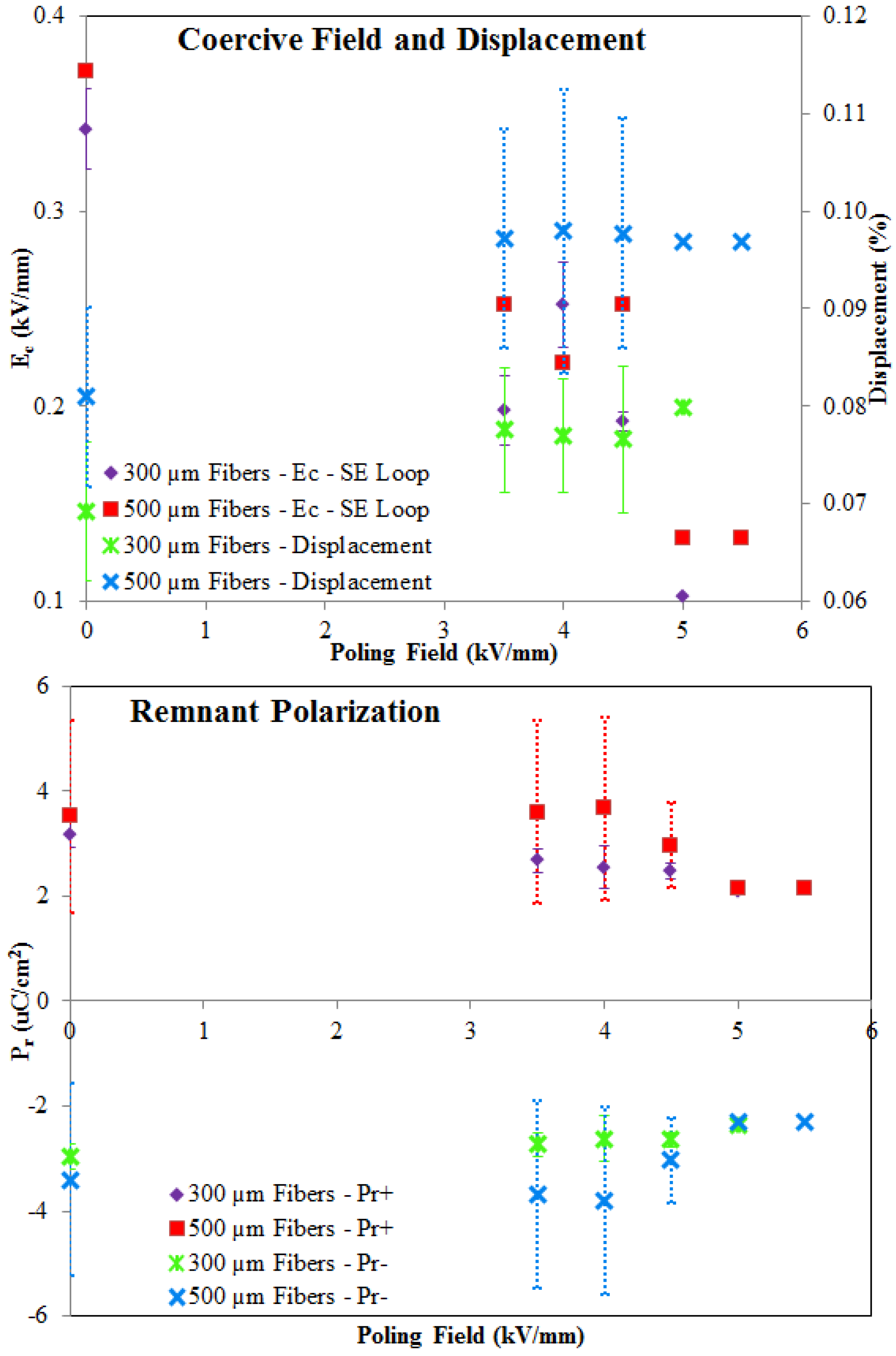
3.2. Electromechanical Investigation

Figure 5 shows a comparison of the strain and polarization responses of KNNT fibers with the two different diameters.
Figure 5. FerroFib comparison of KNNT polarization evolution (P-E) and strain evolution (S-E) loops as a function of the applied electric field (at 0.1 Hz) for 300-µm and 500-µm fibers showing data prior to electrical poling (a,d) and after electrical poling (b,c,e,f). Note: the P-E loops are centered automatically by FerroFib.
Actuators 04 00099 g005
There is an observable tilt present in the P-E loops of both fibers, which is attributed by Lin et al. to the probability that KNNT ceramics may transform from a normal ferroelectric to a relaxor ferroelectric, exhibiting a slim and tilted loop [30,36]. Compositional disorder, i.e., the disorder in the arrangement of different ions within the crystallographic equivalent sites, e.g., the A-site within the perovskite structure, is a common feature of relaxor ferroelectric materials [37], a condition that may be encouraged by the alkali losses observed. The ratio of the polarization saturation (Ps) to the Pr for the 300-µm fibers is much higher than when compared to that of the 500-µm fibers. This occurs when the reverse nucleation of domains occurs before the applied field reverses, which is ascribed to the presence of internal (or external) stress, or if the free charges below the surfaces cannot reach their equilibrium distribution during each half-cycle of the loop. From the EDX and XRD results, the alkali losses observed would serve to create defects within the crystal that are observed in the ferroelectric results in Figure 5 [35,38].
The higher Na-K ratio in the 300-µm fibers seen from EDX and XRD resulted in samples with lower deformation, as suggested by Zhao et al. [32], though unlike Zhao et al., the effect observed with the grain size resembled that of Zhang et al., whereby with an increasing Na-K ratio, the grain size decreased [39], and the effect on Pr was more related to the effect seen in Du et al., where an optimum ratio of 54:46 of Na-K was found, after which any increase in the ratio led to a decrease in the Pr [40]. The differing hypotheses from the various groups suggest that the results improve to a certain optimum where the greatest amount of phases exist, i.e., MPT, and then decrease, as was seen in Du et al., as the alkali content moves away from the MPT.
From computer simulations, Soh et al. predicted that because of the eigenstrain (the generic name for thermal expansions, phase transformations, initial strains, plastic strains and misfit strains; it explains the inhomogeneity of polycrystalline deformation) induced by polarization switching and the elastic strain caused by the mechanical loading, the symmetry of the butterfly loop can be affected by the coupled electro-mechanical loading [41,42], thus explaining the asymmetrical KNNT S-E loops. Kobayashi et al. suggest that alkali vacancies (common with KNN-based materials), which occur during powder synthesis or volatilization during sintering, may result in point defects [43], which may be the source of the eigenstrain.
Figure 6 shows a graphical representation of the measured values of the coercive field and displacement with the calculated experimental error.
Figure 6. Graphical display of KNNT coercive field and displacement as a function of the applied electric field (at 0.1 Hz) for 300-µm and 500-µm fibers with error bars. Note: Ec values are from non-centered S-E loops.
Actuators 04 00099 g006
The error bars (Figure 6) suggest higher uncertainty, with the 500-µm fibers indicating the hypothesis that with increasing fiber diameter, the porosity decreases, whereas the grain size increases (Table 2). This higher densification rate is attributed to two effects. First, the diffusion paths for the gases generated during the debinding process are shorter in fibers with smaller dimensions. It can be noted that the Ec generally decreases as the poling field increases, as expected for each fiber diameter. The effect of microstructure on Ec for either fiber is minimal, as in Du et al. and Mgbemere et al., where a trend in Ec as the Na-K ratio increased was not observed [40,44]. As a result, the gaseous decomposition products are transported more rapidly to the fiber surfaces and do not become trapped in the pores. The second effect occurs when in the case of PZT, a PbO atmosphere is used, which is known to support the densification process by forming a liquid phase, and due this difference in the PbO content, the addition of the PbO powder into the crucible shows that diffusion processes play an important role [45]. Therefore, larger fiber diameters introduce wider variation in porosity and grain size, and thus, while the larger internal core increases the measured properties, the larger external shell may influence these properties to a larger extent when compared to smaller diameter fibers.
An alkali ion imbalance affects the electrical functionality of the thick film and may be a reason for the high tanδ [35,46]. Deviation from the Na-K ratio can affect the elastic properties, which can vary by as much as 5%, the piezoelectric properties by 10% and the dielectric properties by 20%, within the same batch [47]. The 500-µm fibers had a larger deformation when compared to that of the 300-µm fibers, which also had a larger alkali-ion imbalance.
The measured small signal electromechanical properties of the 300-µm and 500-µm KNNT fiber are shown in Table 4.
Table 4. The electromechanical properties of 300-µm and 500-µm KNNT fibers at 10 Hz.
Poled at 3.5 kV/mmPoled at 4.0 kV/mmPoled at 4.5 kV/mmPoled at 5.0 kV/mm
Piezoelectric Coefficientd33 (pC/N)
300-µm Fibers62 ± 565 ± 664 * ± 666 **
500-µm Fibers97 ± 2289 ± 35101* ± 32102 **
Dielectric Loss% tanδ
300-µm Fibers7 ± 0.67 ± 0.26 * ± 0.26 **
500-µm Fibers13 ± 4.314 ± 4.011* ± 0.910 **
Relative Permittivityεt33
300-µm Fibers1967 ± 1661958 ± 1781903 * ± 881834 **
500-µm Fibers1281 ± 1391151 ± 2141185 * ± 471241 **
* Average of 3 fibers; ** single fiber.
In Zheng et al., it was revealed that domain structure and relative density play substantial roles in determining the dielectric permittivity and the piezoelectric constant behaviours [48]. The 500-µm fibers had a larger grain size and also had larger d33, though with a smaller relative permittivity. In Barzegar et al., they show that for a small aspect ratio (thickness/lateral dimension <0.1), the measured d33 is as much as 30% lower than the true value. The measured d33 increases with increasing aspect ratio and reaches its true value at a threshold aspect ratio that is dependent on the ceramic composition [49]. The aspect ratio of the 500-µm fibers is naturally larger than that of the 300-µm fiber and shows a larger d33 when compared to that of the 300-µm fiber. Poor stoichiometry observed in the small diameter fibers also impacted the piezoelectric properties negatively [35].
The relative dielectric constant is just as it name implies, a constant, and does not change very much for a particular material, over a wide range of frequencies. Therefore, the differences observed may suggest differences in chemical, grain size or phase structure. This is confirmed by the XRD and EDX elemental analysis. In ferroelectric materials, the grain size is known to affect the relative permittivity of the material with maximum properties reported at 0.8–1-µm grain sizes. A smaller grain size results in an increase in internal stresses and an increase in εr [27].

4. Conclusions

KNNT fibers with two different fiber diameters were successfully produced. A small quantity of powder (1–5 g) was used to produce ferroelectric fibers with diameters of between 300 µm and 500 µm. The grain size and porosity were significantly influenced by fiber diameter, despite sintering the fibers under similar conditions (i.e., KNNT powder bed, closed in an alumina crucible and sealed with alumina powder). The effect of the different fiber diameters on the microstructure was shown by the phase composition (XRD) and elemental concentration (EDX), with a reduced Na-K ratio in the 300-µm fibers, where the decreased fiber diameter was shown to result in an increase in the porosity, whereas the grain size decreased.
Large diameter (500 µm) fibers show an increase in most electromechanical properties measured, i.e., d33, tanδ, Pr, Ec and the free longitudinal fiber displacement, when compared to smaller diameter (300 µm) fibers. The hypothesis for this result is that a larger grain size, higher density and lower alkali losses aid the phase formation during sintering, leading to improved electromechanical properties. While Gupta et al. suggest a material with a higher surface area results in a much more dense sintered material [50], the result in this study was the opposite, because as suggested in Heiber et al., the chemical and, thus, the phase composition vary across the radius of the fibers for both fiber diameters, with the gradients likely more pronounced for the higher surface area fibers (i.e., fibers with smaller diameters) [18].
In comparison to KNN fibers [16], the electromechanical properties can be improved using KNNT with tantalum as a B-site substituent for fiber production. The low coercive field and high dielectric constant make them interesting for lead-free-based actuator applications.

Acknowledgments

The authors would like to acknowledge the COST Action MP0904 Single- and multiphase ferroics and multiferroics with restricted geometries (SIMUFER); State Secretariat for Education, Research and innovation (SERI) No. C11.0142; the Swiss National Science Foundation (SNSF) No. 206021 133833; for financing the project and the new equipment. This work was supported by the Basic Science Research Program through the National Research Foundation of Korea (NRF) funded by the Ministry of Education, Science and Technology (MEST) (2011-0030058).

Author Contributions

Tony Lusiola—conception and design, acquisition of data, analysis and interpretation of data;
Ali Hussain—conception and design, acquisition of data, analysis and interpretation of data;
Myong Ho Kim—supervision and interpretation of data;
Thomas Graule—supervision and interpretation of data;
Frank Clemens—conception, design, analysis, interpretation of data and supervision.

Conflicts of Interest

The authors declare no conflict of interest.

References

  1. Stavber, G.; Malic, B.; Kosec, M. A road to environmentally friendly materials chemistry: Low-temperature synthesis of nanosized K0.5Na0.5NbO3 powders through peroxide intermediates in water. Green Chem. 2011, 3, 1303–1310. [Google Scholar] [CrossRef]
  2. Hansen, K.; Astafiev, K.; Zawada, T. Lead-free piezoelectric thick films based on potassium sodium niobate solutions. In Proceedings of the IEEE International Ultrasonics Symposium (IUS), Rome, Italy, 20–23 September 2009; pp. 1738–1741.
  3. Wu, J.; Xiao, D.; Zhu, J. Potassium−Sodium Niobate Lead-Free Piezoelectric Materials: Past, Present, and Future of Phase Boundaries. Chem. Rev. 2015, 115, 2559–2595. [Google Scholar] [CrossRef] [PubMed]
  4. Saito, Y.; Takao, H.; Tani, T.; Nonoyama, T.; Takatori, K.; Homma, T.; Nagaya, T.; Nakamura, M. Lead-free piezoceramics. Nature 2004, 432, 84–87. [Google Scholar] [CrossRef] [PubMed]
  5. Damjanovic, D.; Klein, N.; Li, J.; Porokhonskyy, V. What can be expected from lead-free piezoelectric materials? Funct. Mater. Lett. 2010, 3, 5–13. [Google Scholar] [CrossRef]
  6. López-Juárez, R.; González, F.; Villafuerte-Castrejón, M.E. Lead-Free Ferroelectric Ceramics with Perovskite Structure. In Ferroelectrics - Material Aspects; Lallart, M., Ed.; InTech: Rijeka, Croatia, 2011; pp. 305–330. [Google Scholar]
  7. Wang, X.; Wu, J.; Xiao, D.; Zhu, J.; Cheng, X.; Zheng, T.; Zhang, B.; Lou, X.; Wang, X. Giant Piezoelectricity in Potassium−Sodium Niobate Lead-Free Ceramics. J. Am. Chem. Soc. 2014, 136, 2905–2910. [Google Scholar] [CrossRef] [PubMed]
  8. Rödel, J.; Jo, W.; Seifert, K.T.P.; Anton, E.M.; Granzow, T.; Damjanovic, D. Perspective on the Development of Lead-free Piezoceramics. J. Am. Ceram. Soc. 2009, 92, 1153–1177. [Google Scholar] [CrossRef]
  9. Matsubara, M.; Yamaguchi, T.; Sakamoto, W.; Kikuta, K.; Yogo, T.; Hirano, S.-I. Processing and Piezoelectric Properties of Lead-Free (K,Na)(Nb,Ta)O3 Ceramics. J. Am. Ceram. Soc. 2005, 88, 1190–1196. [Google Scholar] [CrossRef]
  10. Xiong, P.; Tan, G.Q.; Ren, H.J. Influence of Ta5+ Doping on the Piezoelectric Properties of KNN Ceramics. Key Eng. Mater. 2012, 512–515, 1399–1402. [Google Scholar] [CrossRef]
  11. Lee, J.H.; Ryu, G.H.; Do, D.; Song, T.K.; Kim, M.H.; Park, T.G.; Kim, W.J.; Kim, S.S.; Sung, Y.S.; Baik, S. Effects of A-Site Nonstoichiometry on Dielectric and Piezoelectric Properties of Pb-Free (Na0.53+xK0.47)(Nb0.55Ta0.45)O3 Ceramics. Integr. Ferroelectr. 2012, 133, 67–72. [Google Scholar] [CrossRef]
  12. Schönecker, A. Piezoelectric and Acoustic Materials for Transducer; Ahmad Safari, E.K.A., Ed.; Springer: New York, NY, USA, 2008. [Google Scholar]
  13. Janas, V.F.; Safari, A. Overview of fine-scale piezoelectric ceramic/polymer composite processing. J. Am. Ceram. Soc. 1995, 78, 2945–2955. [Google Scholar] [CrossRef]
  14. Selemani, S. Characterization of Modified Rosen-Type Piezoelectric. Sens. Trans. J. 2007, 79, 1186–1191. [Google Scholar]
  15. Ismael, M.R.; Clemens, F.; Graule, T.; Hoffmann, M.J. Effects of different thermoplastic binders on the processability of feedstocks for ceramic co-extrusion process. Ceram. Int. 2011, 37, 3173–3182. [Google Scholar] [CrossRef]
  16. Lusiola, T.; Scharf, D.; Graule, T.; Clemens, F. Low Shear Compounding Process for Thermoplastic Fabrication of Ferroelectric Lead-Free Fibres. J. Eur. Ceram. Soc. 2014, 34, 2265–2274. [Google Scholar] [CrossRef]
  17. Belloli, A.; Heiber, J.; Clemens, F.; Ermanni, P. Novel Characterization Procedure for Single Piezoelectric Fibers. J. Intell. Mater. Syst. Struct. 2009, 20, 355–363. [Google Scholar] [CrossRef]
  18. Heiber, J.; Clemens, F.; Helbig, U.; de Meuron, A.; Soltmann, Ch.; Graule, T.; Hülsenberg, D. Properties of Pb(Zr,Ti)O3 fibres with a radial gradient structure. Acta Mater. 2007, 55, 6499–6506. [Google Scholar] [CrossRef]
  19. Heiber, J.; Belloli, A.; Ermanni, P.; Clemens, F. Ferroelectric Characterization of Single PZT Fibers. J. Intell. Mater. Syst. Struct. 2009, 20, 379–385. [Google Scholar] [CrossRef]
  20. Cho, K.H.; Lee, H.Y. Pore-dependent dielectric and electrical properties of barium titanate ceramic. In Proceedings of the Ninth IEEE International Symposium on Applications of Ferroelectrics, University Park, PA, USA, 7–10 August 1994; pp. 566–571.
  21. Miclea, C.; Tanasoiu, C.; Spanulescu, I.; Miclea, C.F.; Gheorghiu, A.; Amarande, L.; Cioangher, M.; Miclea, C.T. Microstructure and Properties of Barium Titanate Ceramics Prepared by Mechanochemical Synthesis. Romanian. J. Inform. Sci. Technol. 2007, 10, 335–345. [Google Scholar]
  22. Cheng, H.L.; Zhou, W.C.; Du, H.L.; Luo, F.; Zhu, D.M. Effects of dwell time during sintering on electrical properties of 0.98(K0.5Na0.5)NbO3−0.02LaFeO3 ceramics. Trans. Nonferr. Metals Soc. Chin. 2013, 23, 2984–2988. [Google Scholar] [CrossRef]
  23. Swain, S.; Kumar, P.; Agrawal, D.K.; Sonia. Dielectric and ferroelectric study of KNN modified NBT ceramics synthesized by microwave processing technique. Ceram. Int. 2013, 39, 3205–3210. [Google Scholar] [CrossRef]
  24. Hussain, A.; Kim, J.S.; Song, T.K.; Kim, M.H.; Kim, W.J. Fabrication of textured KNNT ceramics by reactive template grain growth using NN templates. Curr. Appl. Phys. 2013, 13, 1055–1059. [Google Scholar] [CrossRef]
  25. GARINO, T.J.; Bowen, H.K. Deposition and sintering of particle films on a rigid substrate. J. Am. Ceram. Soc. 1987, 70, C-315–C-317. [Google Scholar]
  26. Dorey, R.A.; Whatmore, R. Electroceramic Thick Film Fabrication for MEMS. J. Electroceram. 2004, 12, 19–32. [Google Scholar] [CrossRef]
  27. Dorey, R. Ceramic Thick Films for MEMS and Microdevices; William Andrew Publishing: Norwich, NY, USA, 2011. [Google Scholar]
  28. Randall, C.A.; Kim, N.; Kucera, J.P.; Cao, W.; Shrout, T.R. Intrinsic and Extrinsic Size Effects in Fine-Grained Morphotropic-Phase-Boundary Lead Zirconate Titanate Ceramics. J. Am. Ceram. Soc. 1998, 81, 677–688. [Google Scholar] [CrossRef]
  29. Hattori, T.; Kitanaka, Y.; Noguchi, Y.; Miyayama, M. Growth and ferroelectric/piezoelectric properties of (K,Na)(Nb,Ta)O3 ferroelectric single crystals. Key Eng. Mater. 2013, 566, 64–67. [Google Scholar] [CrossRef]
  30. Lee, S.Y.; Ahn, C.W.; Kim, J.S.; Ullah, A.; Lee, H.J.; Hwang, H.-I.; Choi, J.S.; Park, B.S.; Kim, I.W. Enhanced piezoelectric properties of Ta substituted-(K0.5Na0.5)NbO3 films: A candidate for lead-free piezoelectric thin films. J. Alloys Compd. 2011, 509, L194–L198. [Google Scholar] [CrossRef]
  31. Lusiola, T.; Bortolani, F.; Zhang, Q.; Dorey, R. Molten hydroxide synthesis as an alternative to molten salt synthesis for producing (K0.5Na0.5)NbO3 lead free ceramics. J. Mater. Sci. 2012, 47, 1938–1942. [Google Scholar] [CrossRef] [Green Version]
  32. Zhao, T.L.; Guo, Z.L.; Wang, C.M. The Effects of Na/K Ratio on the Electrical Properties of Sodium-Potassium Bismuth Titanate Na0.5Bi4.5Ti4O15–K0.5Bi4.5Ti4O15. J. Am. Ceram. Soc. 2012, 95, 1062–1067. [Google Scholar] [CrossRef]
  33. Taub, J.; Ramajo, L.; Castro, M.S. Phase structure and piezoelectric properties of Ca- and Ba-doped K1/2Na1/2NbO3 lead-free ceramics. Ceram. Int. 2013, 39, 3555–3561. [Google Scholar] [CrossRef]
  34. Wang, L.; Yao, K.; Goh, P.C.; Ren, W. Volatilization of alkali ions and effects of molecular weight of polyvinylpyrrolidone introduced in solution-derived ferroelectric K0.5Na0.5NbO3 films. J. Mater. Res. 2009, 24, 3516–3522. [Google Scholar] [CrossRef]
  35. Li, M.; Feteira, A.; Mirsaneh, M.; Lee, S.; Lanagan, M.T.; Randall, C.A.; Sinclair, D.C. Influence of nonstoichiometry on extrinsic electrical conduction and microwave dielectric loss of BaCo1/3Nb2/3O3 ceramics. J. Am. Ceram. Soc. 2010, 93, 4087–4095. [Google Scholar] [CrossRef]
  36. Lin, D.; Kwok, K.W.; Chan, H.L.W. Phase transition and electrical properties of (K0.5Na0.5)(Nb1-xTax)O3 lead-free piezoelectric ceramics. Appl. Phys. A. 2008, 91, 167–171. [Google Scholar] [CrossRef]
  37. Bokov, A.A.; Ye, Z.G. Recent progress in relaxor ferroelectrics with perovskite structure. J. Mater. Sci. 2006, 41, 31–52. [Google Scholar] [CrossRef]
  38. Lines, M.E.; Glass, A.M. Principles and Applications of Ferroelectrics and Related Materials; Oxford University Press: Oxford, UK, 1977. [Google Scholar]
  39. Zhang, Q.; Zhang, B.; Li, H.; Shang, P. Effects of Na/K ratio on the phase structure and electrical properties of NaxK1−xNbO3 lead-free piezoelectric ceramics. Rare Metals 2010, 29, 220–225. [Google Scholar] [CrossRef]
  40. Du, H.; Shu, S.; Xu, Z.; Wei, X.; Zhuo, W.; Zhu, D.; Fa, L. Na/K Ratios Dependence of Piezoelectric & Ferroelectric Properties in (K1-xNax)NbO3 Lead-Free Ceramics. J. Adv. Dielectr. 2011, 1, 471–478. [Google Scholar] [CrossRef]
  41. Soh, A.K.; Song, Y.C.; Ni, Y. Phase Field Simulations of Hysteresis and Butterfly Loops in Ferroelectrics Subjected to Electro-Mechanical Coupled Loading. J. Am. Ceram. Soc. 2006, 89, 652–661. [Google Scholar] [CrossRef]
  42. Mura, T. Micromechanics of Defects in Solids; Springer: Dordrecht, Netherlands, 1987. [Google Scholar]
  43. Kobayashi, K.; Shimizu, H.; Doshidai, Y.; Mizuno, Y.; Randall, C.A. Defect Structure and Morphology of Alkali Niobate (Na0.5K0.5)NbO3 Powder Calcined under Low Oxygen Partial Pressure. Appl. Phys. Express 2013, 6, 101502–101504. [Google Scholar] [CrossRef]
  44. Mgbemere, H.E.; Herber, R.P.; Schneider, G.A. Investigation of the dielectric and piezoelectric properties of potassium sodium niobate ceramics close to the phase boundary at (K0.35Na0.65)NbO3 and partial substitutions with lithium and antimony. J. Eur. Ceram. Soc. 2009, 29, 3273–3278. [Google Scholar] [CrossRef]
  45. Heiber, J.; Clemens, F.; Graule, T.; Hülsenberg, D. Influence of the Fibre Diameter on the Microstructure and the Piezoelectric Properties of PZT-Fibres. Adv. Sci. Technol. 2006, 45, 2459–2463. [Google Scholar] [CrossRef]
  46. Zeng, J.T.; Kwok, K.W.; Chan, H.L.W. KxNa1−xNbO3 powder synthesized by molten-salt process. Mater. Lett. 2007, 61, 409–411. [Google Scholar] [CrossRef]
  47. Jordan, T.L.; Ounaies, Z. Piezoelectric Ceramics Characterization; ICASE Report No. 2001–28; NASA Langley Research Center, ICASE: Hampton, VA, USA, 2001.
  48. Zheng, P.; Zhang, J.L.; Tan, Y.Q.; Wang, C.L. Grain-size effects on dielectric and piezoelectric properties of poled BaTiO3 ceramics. Acta Mater. 2012, 60, 5022–5030. [Google Scholar] [CrossRef]
  49. Barzegar, A.; Damjanovic, D.; Setter, N. The effect of boundary conditions and sample aspect ratio on apparent d33 piezoelectric coefficient determined by direct quasistatic method. IEEE Trans. Ultrason. Ferroelectr. Freq. Control 2004, 51, 262–270. [Google Scholar] [PubMed]
  50. Gupta, M.; Leong, E.W.W. Microwaves and Metals; Wiley: Hoboken, NJ, USA, 2011. [Google Scholar]

