Article

Ultrasonic Transducer Fabricated Using Lead-Free BFO-BTO+Mn Piezoelectric 1-3 Composite

1
The Hong Kong Polytechnic University, Shenzhen Research Institute, Shenzhen 518057, China
2
Department of Applied Physics, The Hong Kong Polytechnic University, Hong Kong, China
3
College of Chemistry and Materials Science, Sichuan Normal University, Chengdu 610066, China
*
Author to whom correspondence should be addressed.
These authors contributed equally to this work.
Actuators 2015, 4(2), 127-134; https://doi.org/10.3390/act4020127
Submission received: 1 April 2015 / Revised: 12 May 2015 / Accepted: 27 May 2015 / Published: 29 May 2015
(This article belongs to the Special Issue Feature Papers)

Abstract

:
Mn-doped 0.7BiFeO3-0.3BaTiO3 (BFO-0.3BTO+Mn 1% mol) lead-free piezoelectric ceramic were fabricated by traditional solid state reaction. The phase structure, microstructure, and ferroelectric properties were investigated. Additionally, lead-free 1–3 composites with 60% volume fraction of BFO-BTO+Mn ceramic were fabricated for ultrasonic transducer applications by a conventional dice-and-fill method. The BFO-BTO+Mn 1-3 composite has a higher electromechanical coupling coefficient (kt = 46.4%) and lower acoustic impedance (Za ~ 18 MRayls) compared with that of the ceramic. Based on this, lead-free piezoelectric ceramic composite, single element ultrasonic transducer with a center frequency of 2.54 MHz has been fabricated and characterized. The single element transducer exhibits good performance with a broad bandwidth of 53%. The insertion loss of the transducer was about 33.5 dB.

1. Introduction

Lead-based ceramics, especially Pb(Zr,Ti)O3 (PZT), are the most extensively used piezoelectric ceramics for transducer applications due to their stable and good piezoelectric properties [1,2,3,4]. However, environmental problems are caused by preparing lead-based ceramics because of PbO volatility. Recently, lead-free piezoelectric materials with relatively good piezoelectric properties have attracted a great deal of attention owing to environmental conservation [5]. Therefore, the lead-free ceramics were used in various applications, such as ultrasonic transducers [6,7,8,9], pyroelectric sensors [10] and actuators [11,12].
BFO-BTO system is proposed to be an important family of high-performance lead-free piezoelectric ceramics because of its good ferroelectric properties [13,14,15,16,17]. Additionally, Mn doping is a common method to enhance the piezoelectric properties and reduce the dielectric loss of the piezoelectric materials [15,16], thus, Mn modified BFO-BTO ceramic with good ferroelectric properties was chosen for transducer applications.
In order to further improve the performance of transducer, such as detecting highly attenuative materials in non-destructive evaluation applications or acquiring high resolution ultrasonic imaging in medical field [18,19,20,21]. The 1-3 composite was widely used for further enhancing the acoustic and electrical properties of transducers due to its lower acoustic impedance Z and higher kt compared to the single phase ceramic [22].
Therefore, in this work, lead-free BFO-BTO+Mn ceramic was characterized, and a single-element ultrasonic transducer was fabricated and characterized using the BFO-BTO+Mn ceramic/epoxy 1-3 composite.

2. Experimental Section

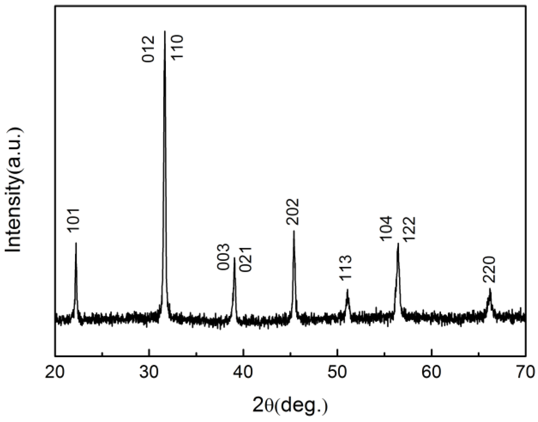
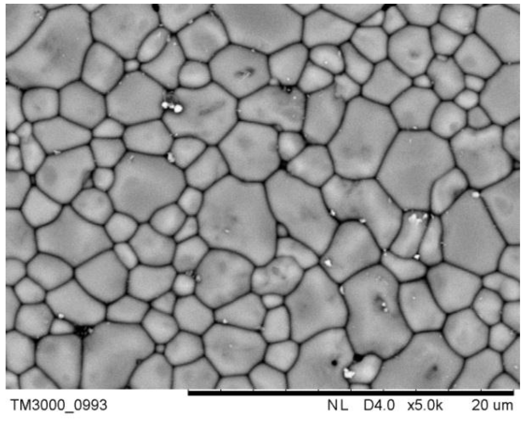
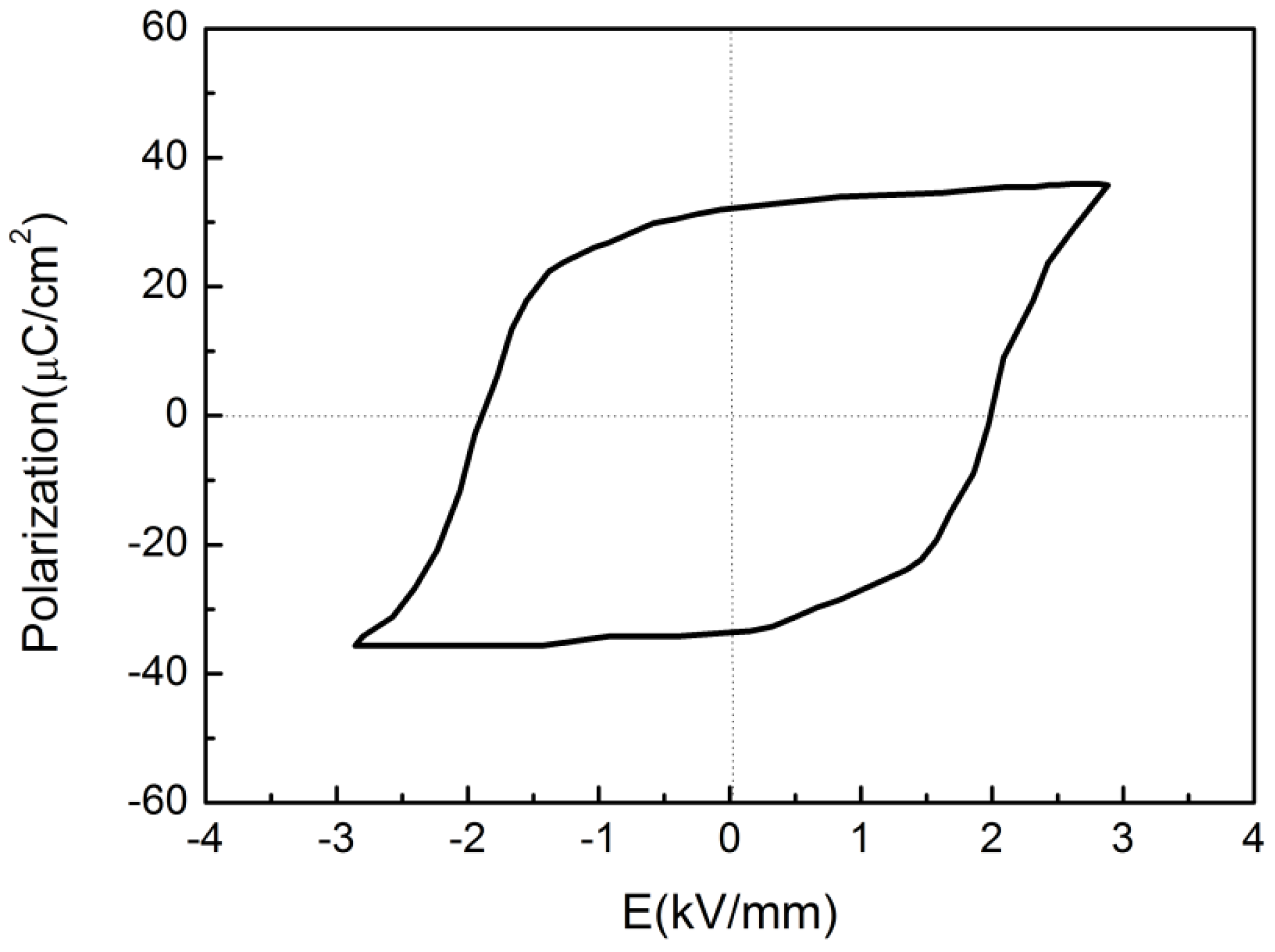
2.1. Ceramic Characterization

Mn-doped BiFeO3-0.3BaTiO3 lead-free piezoelectric ceramic were fabricated by a traditional solid state reaction using metal oxides and carbonate powders. The crystalline structure of the ceramic was identified by an X-ray diffraction (XRD) diffractometer (SmartLab, Rigaku Co., Tokyo, Japan). The microstructure was characterized using scanning electron microscopy (SEM, TM3000, HITACHI, Japan). The bulk ceramic density was measured by the Archimedes method. The room temperature polarization-electric field (P-E) hysteresis loops were measured using a modified Sawyer Tower circuit at 100 Hz. The sample was poled under 6 kV/mm at 100­­ °C for 15 min in a silicon oil bath. The piezoelectric properties of the samples were calculated following the IEEE standards on piezoelectricity [23]. The dielectric properties of the BFO-BTO+Mn ceramic and its 1-3 composite were measured using an impedance analyzer (Agilent 4294A, Santa Clara, CA, USA).

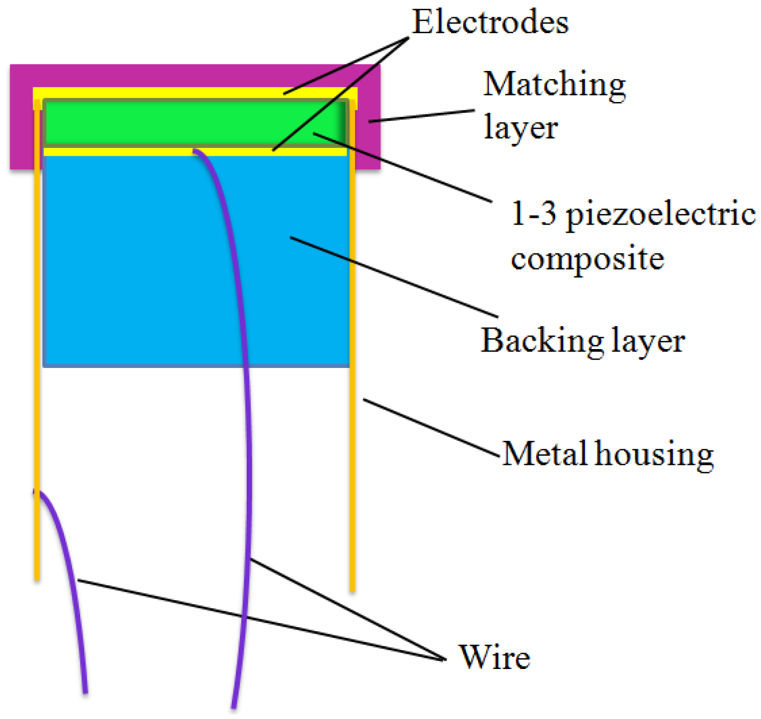
2.2. 1-3 Composite Fabrication

For improving the transducer performance, BFO-BTO+Mn ceramic/epoxy 1-3 composite selected as the active element of the transducer. The composite was fabricated using the traditional dice-and-fill method. A dicing saw with a 50 μm-thick blade was used to dice the sample. The kerf is about 75 μm due to the blade vibration, and the ceramic volume fraction is 60%. The low-viscosity epoxy (Epo-Tek 301, Epoxy Technology, Billerica, MA, USA) was used to fill the kerf. Before the epoxy solidification, the composite sample was vacuumed to remove the bubbles. Then the 1-3 composite was obtained by lapping the excess ceramic and epoxy away. Silver paint (SPI, West Chester, PA, USA) as the electrode was covered on the top and bottom faces of the 1-3 composite disk.

3. Results and Discussion

Figure 1 shows the XRD pattern of the BFO-BTO+Mn ceramic. The sample possesses a typical ABO3 perovskite rhombohedral structure and no secondary phase is observed. This suggests that Mn has diffused into the BFO-BTO lattices to form a homogeneous solid solution.
Figure 1. XRD pattern of the BFO-BTO+Mn ceramic.
Actuators 04 00127 g001
Figure 2 shows the SEM micrograph of the BFO-BTO+Mn ceramic. It can be found that the grain size is about 4 μm and the ceramic is dense and without pores. The density of the ceramic is high with a value of about 7366 kg/m3.
Figure 2. SEM micrograph of the BFO-BTO+Mn ceramic.
Actuators 04 00127 g002
Figure 3 shows the P-E hysteresis loop of the BFO-BTO+Mn ceramic at room temperature. The remnant polarization Pr value is found to be 32 μC/cm2, which is similar to the previous report [16]. The coercive field Ec is about 2 kV/mm. The result suggests that the BFO-BTO+Mn ceramic has good ferroelectric property.
Figure 3. P-E loop of the BFO-BTO+Mn ceramic.
Actuators 04 00127 g003
Figure 4 shows diagram structure of the 1-3 composite transducer. There are four components including a backing layer, 1-3 piezoelectric composite, matching layers, and metal housing. The 1-3 piezoelectric composite with a diameter of 20.8 mm and a thickness 0.75 mm was mounted in a metal housing. The matching layer was placed in front of the 1-3 piezoelectric composite. The backing layer was molded on the rear side of the composite to reduce the ring-down time of the transducer. The geometry of the transducer is a piston structure. Table 1 shows the properties of the BFO-BTO+Mn ceramic, 1-3 composite and PZT ceramic. It can be seen that the electromechanical coupling coefficient kt of the 1-3 composite (46.4%) is higher than that of the ceramic (37.5%) and similar to that of PZT ceramic (46%) [24]. Additionally, the acoustic impedance (Za ~ 17.76 MRayls) of the 1-3 composite is lower compared to that of the BFO-BTO+Mn ceramic (29.84 MRayls) and the PZT ceramic (32.5 MRayls) [24]. The 1-3 composite, with a higher kt and lower Za, is more suitable for transducer applications.
Table 1. Properties of the BFO-BTO+Mn ceramic, 1-3 composite and PZT ceramic.
Materialkt (%)d33 (pC/N)ρ (kg/m3)c (m/s)εTZa (MRayls)
BFO-BTO+Mn Ceramic37.5827366405159629.84
1-3 composite (60%)46.4454800370029017.76
PZT ceramic
[24]
4642077004100185032.5
Single matching layer was designed based on a one-dimensional Krimholtz-Leedom-Matthae (KLM) model software PiezoCAD (Version 3.03 for Windows, Sonic concepts, Wood-inville, WA, USA). The matching layer was fabricated using low-viscosity epoxy (Epo-Tek 301, Epoxy Technology, Billerica, MA, USA) with aluminum oxide powder. The acoustic impedances of the matching layers are 3.98 MRayls. The thickness of the matching layer was designed to be λ/4 (~0.27 mm), where λ is the wavelength of the acoustic wave transmitting in a matching layer at the resonance frequency. The backing layer is epoxy (Epo-Tek 301, Epoxy Technology, Billerica, MA, USA) loaded with larger-size aluminum oxide powder and polymer micro-bubbles. The acoustic impedance of the backing layer is light, about 5.05 MRayls. The thickness of the backing layer was about 10 mm. The properties of the matching and backing materials are shown in Table 2.
Figure 4. Schematic diagram of the 1-3 composite transducer.
Actuators 04 00127 g004
Table 2. Properties of the matching and backing materials.
MaterialsUseρ (kg/m3)c (m/s)Za (MRayls)Thickness (mm)
Aluminum oxide powder/Epo-tek 301Matching layer145327403.980.27
Aluminum oxide powder and micro-bubbles/Epo-tek 301Backing layer172529305.0510
The square of effective electromechanical coupling coefficient keff2, which describes the conversion of energy between electrical and mechanical, was calculated as following [23,25]:
k eff = 1 f s 2 f p 2
where fs is the frequency of the maximum conductance, and fp is the frequency of maximum resistance. For this transducer, the values of the fs and fp are about 2.62 MHz and 2.93 MHz, respectively. Therefore, the value of keff for this transducer is 48.5%.
The performance of the transducer was evaluated using a conventional pulse-echo response measurement method. By connecting to an ultrasonic pulser-receiver (Panametrics 5900PR, Olympus, Japan), the transducer was excited by a 1 μJ electrical pulse with 1 kHz repetition and 50 ohms damping. The echo response was captured by the receiving circuit of the pulser-receiver and displayed on an oscilloscope (Infinium 54810A, HP/Agilent, Santa Clara, CA, USA). The frequency domain pulse-echo response was acquired on the oscilloscope by Fast Fourier Transforms (FFT) math feature.
Based on the PiezoCAD software, the modeled pulse-echo waveform and frequency spectrum of the 1-3 composite transducer is shown in Figure 5a. Compared to the modeled results, the experimental results (Figure 5b) show similar characteristics. It is found that the measured center frequency of the transducer (2.54 MHz) agrees well with the modeled result (2.53 MHz). The experimental bandwidth of the transducers is 53%, which matche quite well with the modeled result (54%). This transducer’s performance is comparable with that of a PZT transducer (1.88 MHz, 56.4%) and BNKLBT lead-free transducer (1.84 MHz, 63.6%) with a similar frequency and structure [6].
Figure 5. (a) Modeled and (b) measured pulse-echo waveform and frequency spectra of the 1-3 composite transducer.
Actuators 04 00127 g005

4. Conclusions

The BFO-BTO+Mn/epoxy 1-3 composite ultrasound transducers have been successfully fabricated. The performance of the transducers have been simulated and measured. The measured bandwidth was found to be 53%. The transducers were found to exhibit low insertion loss of ~33.5 dB. The results suggest that the BFO-BTO+Mn lead-free composites have the potential to be used for ultrasonic transducers.

Acknowledgments

This research was supported by the National key Basic Research Program of China (973 Program) under Grant No. 2013CB632900. Financial support from The Hong Kong Polytechnic University Strategic Importance Plan (No: 1-ZVCG&1-ZV9B).

Author Contributions

Yan Chen wrote the manuscript and performed the experiments, Kai Mei and Chi-Man Wong performed the experiments, Dunmin Lin, Helen L.W. Chan and Jiyan Dai conceived the project and edited the manuscript.

Conflicts of Interest

The authors declare no conflict of interest.

References

  1. Yamamura, T. Ferroelectric Properties of the PbZrO3-PbTiO3 System. Jpn. Appl. Phys. 1996, 35, 5104–5108. [Google Scholar]
  2. Lin, D.M.; Xiao, D.Q.; Zhu, J.G.; Yu, P. Piezoelectric and Ferroelectric Properties of [Bi0.5(Na1-x-yKxLiy)0.5]TiO3 Lead-Free Piezoelectric Ceramics. Appl. Phys. Lett. 2006, 88, 062901:1–062901:3. [Google Scholar] [CrossRef]
  3. Takenaka, T.; Nagata, H. Current Status and Prospects of Lead-Free Piezoelectric Ceramics. J. Eur. Ceram. Soc. 2005, 25, 2693–2700. [Google Scholar] [CrossRef]
  4. Tani, T.; Kimura, T. Reactive Templated Grain Growth Processing for Lead Free Piezoelectric Ceramics. Adv. Appl. Ceram. 2006, 105, 55–63. [Google Scholar] [CrossRef]
  5. Saito, Y.; Takao, H.; Tani, T.; Nonoyama, T.; Takatori, K.; Homma, T.; Nagaya, T.; Nakamura, M. Lead-Free Piezoceramics. Nature 2004, 432, 84–87. [Google Scholar] [CrossRef] [PubMed]
  6. Edwards, G.C.; Choy, G.C.; Chan, H.L.W.; Scott, D.A.; Batten, A. Lead-Free Transducer for Non-Destructive Evaluation. Appl. Phys. A 2007, 88, 209–215. [Google Scholar] [CrossRef]
  7. Chan, H.L.W.; Choy, S.H.; Chong, C.P.; Li, H.L.; Liu, P.C.K. Bismuth Sodium Titanate Based Lead-Free Ultrasonic Transducer for Microelectronics Wirebonding Applications. Ceram. Int. 2008, 34, 773–777. [Google Scholar] [CrossRef]
  8. Choy, S.H.; Wang, X.X.; Chong, C.P.; Chan, H.L.W.; Liu, P.C.K.; Choy, C.L. 0.90(Bi1/2Na1/2)TiO3–0.05(Bi1/2K1/2)TiO3–0.05BaTiO3 Transducer for Ultrasonic Wire bonding Applications. Appl. Phys. A 2006, 84, 313–316. [Google Scholar] [CrossRef]
  9. Yan, X.; Lam, K.H.; Li, X.; Chen, R.; Ren, W.; Ren, X.; Zhou, Q.; Shung, K.K. Lead-Free Intravascular Ultrasound Transducer Using BZT–50BCT Ceramics. IEEE Trans. Ultrason. Ferroelectr. Freq. Control 2013, 60, 1272–1276. [Google Scholar] [PubMed]
  10. Barrel, J.; MacKenzie, K.J.D.; Stytsenko, E.; Viviani, M. Development of Pyroelectric Ceramics for High-Temperature Applications. Mater. Sci. Eng. B 2009, 161, 125–129. [Google Scholar] [CrossRef]
  11. Lam, K.H.; Wang, X.X.; Chan, H.L.W. Lead-Free Piezoceramic Cymbal Actuator. Sens. Actuators A Phys. 2006, 125, 393–397. [Google Scholar] [CrossRef]
  12. Lam, K.H.; Lin, D.M.; Kwok, K.W.; Chan, H.L.W. Lead-Free Piezoelectric-Metal-Cavity (PMC) Actuators. IEEE Trans. Ultrason. Ferroelectr. Freq. Control 2008, 55, 1682–1685. [Google Scholar] [CrossRef] [PubMed]
  13. Li, Y.; Jiang, N.; Lam, K.H.; Guo, Y.Q.; Zheng, Q.J.; Li, Q.; Zhou, W.; Wan, Y.; Lin, D. Structure, Ferroelectric, Piezoelectric, and Ferromagnetic Properties of BiFeO3-BaTiO3-Bi0.5Na0.5TiO3 Lead-Free Multiferroic Ceramics. J. Am. Ceram. Soc. 2014, 97, 3602–3608. [Google Scholar] [CrossRef]
  14. Zheng, Q.J.; Luo, L.L.; Lam, K.H.; Jiang, N.; Guo, Y.Q.; Lin, D. Enhanced Ferroelectricity, Piezoelectricity, and Ferromagnetism in Nd-modified BiFeO3-BaTiO3 Lead-Free Ceramics. J. Appl. Phys. 2014, 116. [Google Scholar] [CrossRef]
  15. Wan, Y.; Li, Y.; Li, Q.; Zhou, W.; Zheng, Q.J.; Wu, X.C.; Xu, C.G.; Zhu, B.P.; Lin, D. Microstructure, Ferroelectric, Piezoelectric, and Ferromagnetic Properties of Sc-Modified BiFeO3-BaTiO3 Multiferroic Ceramics with MnO2 Addition. J. Am. Ceram. Soc. 2014, 97, 1809–1818. [Google Scholar]
  16. Leontsevw, S.O.; Eitel, R.E. Dielectric and Piezoelectric Properties in Mn-Modified (1-x)BiFeO3-xBaTiO3 Ceramics. J. Am. Ceram. Soc. 2009, 92, 2957–2961. [Google Scholar] [CrossRef]
  17. Wang, T.H.; Ding, Y.; Tu, C.S.; Yao, Y.D.; Wu, K.T.; Lin, T.C.; Yu, H.H.; Ku, C.S.; Lee, H.Y. Structure, Magnetic, and Dielectric Properties of (1-x)BiFeO3-xBaTiO3 Ceramics. J. Appl. Phys. 2011, 109, 1–4. [Google Scholar]
  18. Safari, A.; Janas, V.F.; Bandyopadhyay, A. Development of Fine-Scale Piezoelectric Composites for Transducers. AlChE J. 2004, 43, 2849–2856. [Google Scholar] [CrossRef]
  19. Smith, W.A. The Role of Piezocomposites in Ultrasonic Transducers. IEEE Proc. Ultrason. Symp. 1989, 755–766. [Google Scholar]
  20. Gururaja, T.R. Piezoelectrics for Medical Ultrasonic Imaging. Am. Ceram. Soc. Bull. 1994, 73, 50–55. [Google Scholar]
  21. Kim, K.B.; Hsu, D.K.; Ahn, B.; Kim, Y.G.; Barnard, D.J. Fabrication and Comparison of PMN–PT Single Crystal, PZT and PZT-Based 1–3 Composite Ultrasonic Transducers for NDE Applications. Ultrasonics 2010, 50, 790–797. [Google Scholar] [CrossRef] [PubMed]
  22. Zhou, D.; Lam, K.H.; Chen, Y.; Zhang, Q.H.; Chiu, Y.C.; Luo, H.S.; Dai, J.Y.; Chan, H.L.W. Lead-Free Piezoelectric Single Crystal Based 1–3 Composites for Ultrasonic Transducer Applications. Sens. Actuators A Phys. 2012, 182, 95–100. [Google Scholar] [CrossRef]
  23. IEEE Standard on Piezoelectricity. ANSI/IEEE Standard: New York, NY, USA, 1987.
  24. Lam, K.H.; Lin, D.M.; Ni, Y.Q.; Chan, H.L.W. Lead-free Piezoelectric KNN-based Pin Transducer for Structural Monitoring Applications. Struct. Health Monit. 2009, 8, 283–289. [Google Scholar] [CrossRef]
  25. Tressler, J.F. Piezoelectric Transducer Designs for Sonar Applications. In Piezoelectric and Acoustic Materials for Transducer Applications; Safari, A., Akdoğan, E.K., Eds.; Springer Science+Business Media: New York, NY, USA, 2008; p. 219. [Google Scholar]

