Coupling between the Output Force and Stiffness in Different Variable Stiffness Actuators

Singapore Institute of Manufacturing Technology, SIMTech, Singapore, 638075, Singapore
Actuators 2014, 3(3), 270-284; https://doi.org/10.3390/act3030270
Submission received: 12 March 2014
/
Revised: 16 April 2014
/
Accepted: 1 July 2014
/
Published: 11 August 2014
Abstract
:The fundamental objective in developing variable stiffness actuators is to enable the actuator to deliberately tune its stiffness. This is done through controlling the energy flow extracted from internal power units, i.e., the motors of a variable stiffness actuator (VSA). However, the stiffness may also be unintentionally affected by the external environment, over which, there is no control. This paper analysis the correlation between the external loads, applied to different variable stiffness actuators, and their resultant output stiffness. Different types of variable stiffness actuators have been studied considering springs with different types of nonlinearity. The results provide some insights into how to design the actuator mechanism and nonlinearity of the springs in order to increase the decoupling between the load and stiffness in these actuators. This would significantly widen the application range of a variable stiffness actuator.
1. Introduction
Decades ago and when robotics platforms were being introduced to the industry in their manipulator types, the high rigidity of the robot’s structure was a point of pride for their developers. However, later on, the robot philosophy gradually changed into something more human oriented. Today’s robots are not supposed to be solid, isolated and rigid anymore, but rather adaptive, cooperative and compliant entities in our daily life. The new attitudes demand for novel technologies substantially different from those developed for industrial domains, both at the hardware and the software levels. While industrial robots are not able to physically cooperate/interact with humans, humans are fully cooperative with each other. Inspiration from the mechanisms embedded in the human body is a guide map here that can provide solutions for the robot’s hardware. The main challenge, however, is to make the robot’s body soft and compliant, even though robots are basically made of rigid elements. The series elastic actuator (SEA) developed by Pratt [1] was indeed a first attempt toward compliant actuators. In the SEA, a spring, located between the motor’s output and the output link, provides the compliance. However, more can come out from the single spring in the SEA. The spring acts as a low pass filter, which can absorb the shocks and suppress the peak forces during an impact. The dynamic performance of the actuator can also be enhanced by properly exploiting the passive dynamics, thanks to the spring. However, the level of compliance in SEA remains unchanged in all circumstances, which indeed prevents further exploring of the possible benefits of introducing the compliance. To tackle this issue, variable stiffness actuators (VSAs) have been introduced by the researchers. The main difference between a VSA and the SEA is that a VSA can change the stiffness of the output link.
This capability of stiffness regulation (if it is achieved through passive compliant elements) can enhance the robot’s functionality in several perspectives. One of them is safety to humans and the swiftness of motion while the robot is physically interacting or even possibly colliding with the humans and their environment. Efficiency can also be improved through, e.g., natural gait generation [2], adaptation in legged locomotion applications [3] and prosthetics for lower limbs [4]. The adaptability and force accuracy of the interaction can also be increased through adjusting the stiffness. This is vital in applications that require continuous contact and accurate force exchange, such as in “hands-on” assistive devices, rehabilitation [5], exoskeletons [6] and haptics [7]. Furthermore, the ability to tune the stiffness improves the robustness to external perturbations and unpredictable model errors. This could be due to changes of the environment, of the robot kinematics and dynamics or of the dynamics of a human interacting with it. This is often required in tasks, like hammering, holding cups, drumming [8], and typical tasks with tools, such as screwdriving, cutting, polishing [9], drawing [10] or stabilizing a humanoid [11]. Therefore, varying elasticity in actuation is widely acknowledged if it is properly exploited. Therefore, not only the position, but also the level of stiffness should be controlled in a VSA, and thus, it needs two power sources, i.e., motors. In addition, VSA needs a mechanism by which it can adjust the output stiffness; this is called the stiffness adjustment mechanism (SAM). The conceptual scheme of a VSA is plotted in Figure 1.
Figure 1.
The concept of a stiffness adjustment mechanism and transmitted energy within the system.
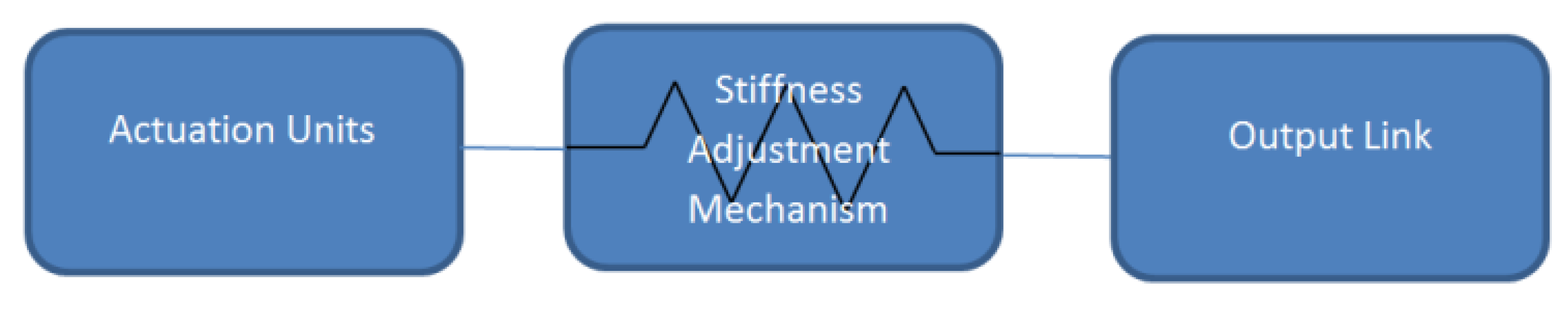
As in each VSA, stiffness and position are two independent parameters that are controlled; the actuation units’ box contains two power sources, i.e., motors. The stiffness adjustment mechanism (SAM) box includes compliant elements, e.g., springs.
The SAM of a VSA defines how the stiffness can be adjusted through the imposed forces. These forces may come from either of SMA’s neighbor boxes, i.e., the actuation unit box or the output link box. However, the fundamental objective in developing a VSA is to enable the actuator to deliberately tune its stiffness through controlling the energy flow extracted from internal power units, i.e., motors. The important fact is that there is no control over the external forces, as a VSA may deal with a known environment. Therefore, generally, if the stiffness is affected by the external force imported through the output link, then the actuation units have to consume energy to compensate for the unintended changes of the stiffness.
Therefore how the stiffness is coupled to the output force is an important criterion that determines the application range of a VSA. In an optimal case, the stiffness is completely decupled from the output force. This means that stiffness is only a function of the control inputs, and when it is fixed to a value, no additional energy is required, as it remains unchanged, regardless of the output load. Therefore, the coupling between stiffness and the external force is an important determinant for any SAM. This level is, in fact, determined by two factors: (1) how the stiffness is adjusted; and (2) the energy saving function (nonlinearity) of the springs.
From this perspective, the main goal of this paper is to develop a comprehensive and systematic framework that analyzes and evaluates the performance of different SAMs with different embedded springs based on the coupling between the external force and the stiffness. Five classes of SAMs are analyzed based on four different types of spring.
The structure of the paper is as follow: in Section 2, the classification of different SAMs is presented. Section 3 analyzes the performances of different SAMs with different types of spring with respect to the coupling between external force and the stiffness. The results are presented in Section 4. Finally, Section 5 presents the conclusion and future works.
2. SAM Classifications
There is a large variety of SAMs employed in different VSAs. In order to systematically analyze and compare their performance, a classification among them is required. In this paper, the classification is based on the arrangement of the actuation units, compliant elements and the output link. Likewise, the conceptual designs of such mechanisms are classified into two main mechanism approaches, namely, antagonists and series.
2.1. Antagonistic Mechanisms
Antagonistic mechanisms are similar to the arrangement of biceps and triceps in the human arm. As the biceps contracts and the triceps relax, the arm is flexed. In an opposite way, as the triceps contracts and the biceps relax, the arm extends. One of the reasons why an antagonistic setup is required is the fact that muscles can only pull and not push. However, more can be achieved with this setup: when both biceps and triceps contract, the elbow becomes stiff; when they both relax, the elbow becomes very compliant, and the arm hangs freely. In reality, the muscles in the human arm are controlled in a continuous manner, and thus, the system can cover a range of positions and compliant behavior.
Similarly, in antagonistic mechanisms, two motors are antagonistically actuating a link through nonlinear springs placed between the motors and the link. Based on different arrangements of the motors and springs, these types of VSAs can be categorized into three classes: simple unidirectional, cross-coupling and bidirectional configurations.
2.1.1. Simple Antagonistic Mechanism (C1)
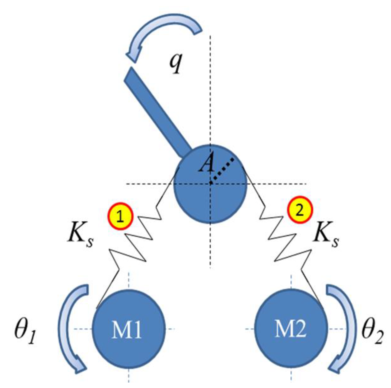
In the simplest type of antagonistic mechanisms, as is shown in Figure 2, each actuation unit is connected to the output link through a nonlinear unidirectional spring. Unidirectional springs can apply force in only one direction (either push or pull the output link). Biologically inspired joint stiffness control [12], actuator with mechanically adjustable series compliance (AMASC) [13] and plated pneumatic artificial muscles (PPAM) [14] use this mechanism to change the stiffness.
Figure 2.
Simple antagonistic class of a stiffness adjustment mechanism.

2.1.2. Cross-coupled Antagonistic Mechanism (C2)
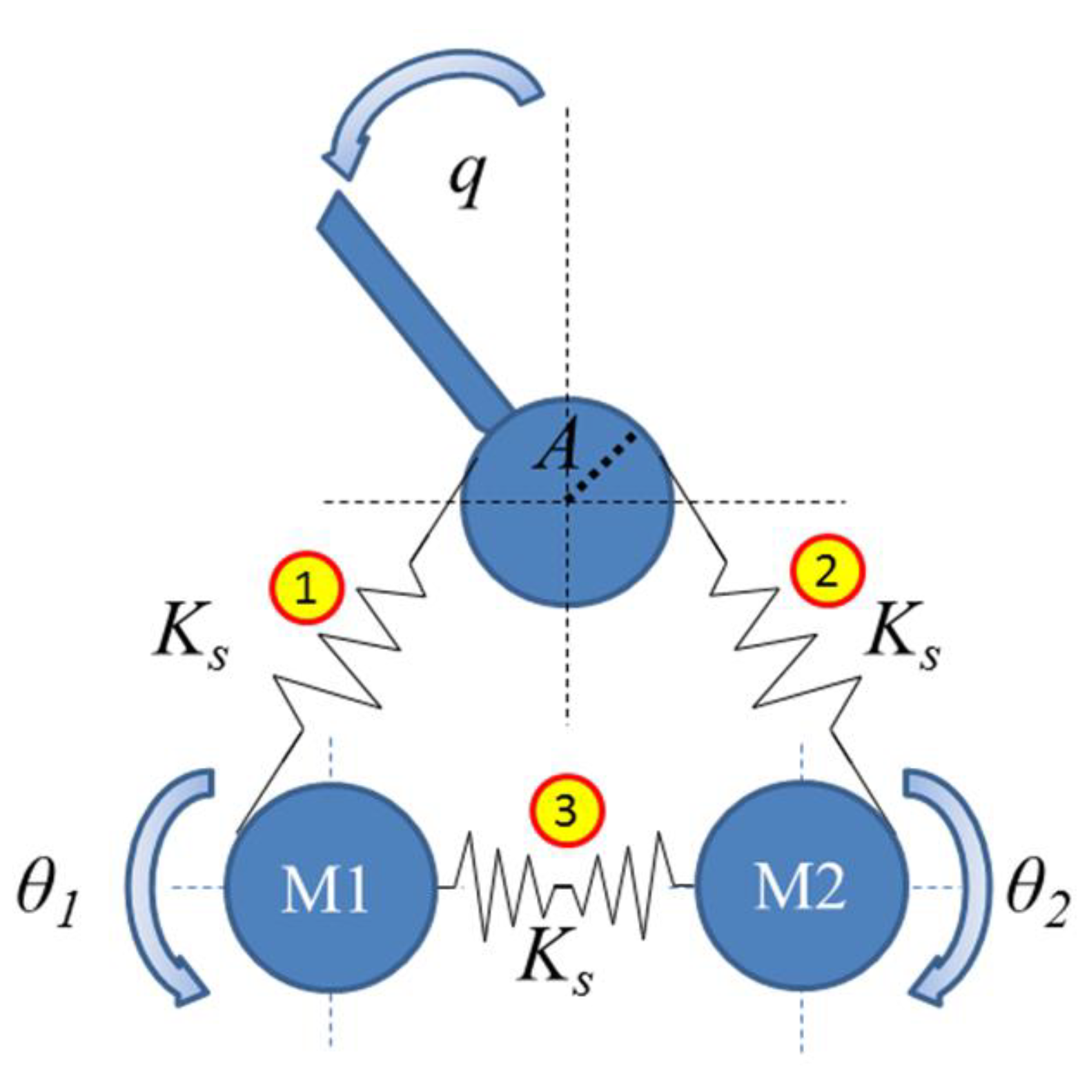
In this class, one additional nonlinear spring is placed between two actuation units; see Figure 3. These additional springs have a two-fold role: they provide pre-loading and also permit the full steering of the link by each actuator. Thanks to that, the maximum generated torque per actuation unit can be set to half of the maximum torque of the similar unidirectional mechanism to obtain an equivalent maximum torque at the link-joint. The variable stiffness actuator (VSA) [15] is an example of this mechanism.
Figure 3.
Cross-coupled class of stiffness adjustment mechanism.

2.1.3. Bidirectional Antagonistic Mechanism (C3)
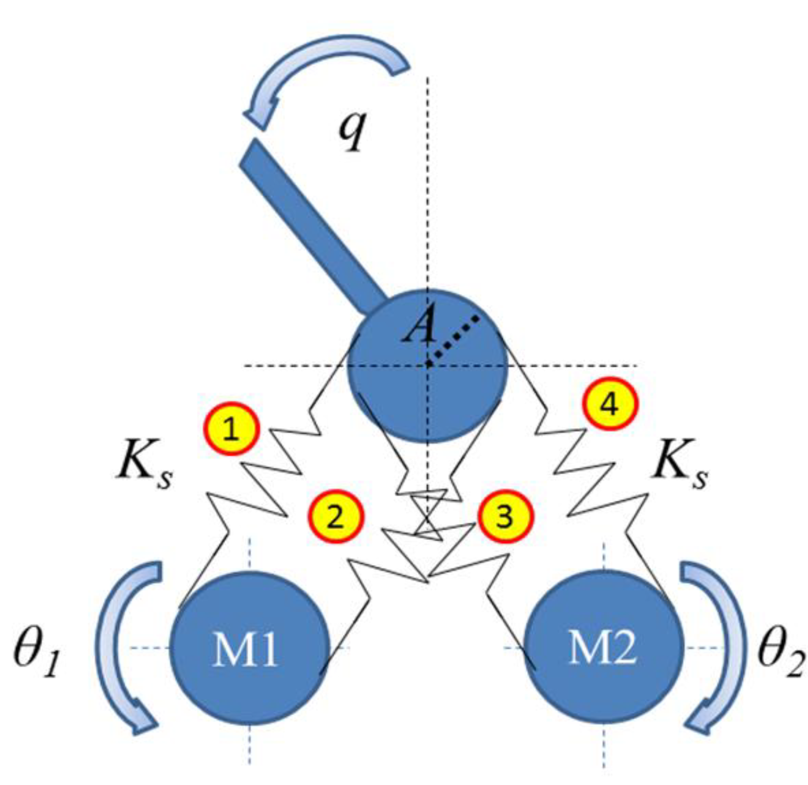
In this class, each actuation unit is connected to the output link through a pair of nonlinear springs; see Figure 4. In this way, each actuation unit is able to push and pull the output link due to the bidirectional arrangement of corresponding nonlinear springs. This again allows transmitting the maximum generated torque of each actuation units to the output link. Variable stiffness actuator-II (VSA-II) [16], VSA-CUBE [17], bidirectional antagonism with variable stiffness (BAVS) [18] and quasi-antagonistic joint (QA-joint) [19] mechanism are examples of this.
Figure 4.
Bidirectional class of stiffness adjustment mechanism.
2.2. Series Mechanisms
In the other design approach, one motor with a spring in series is dedicated to the link positioning, and another motor changes the stiffness, independently. Since, in this approach, two motors are in series, it is called the series mechanism approach. In most of the series VSAs in this group, the spring’s pretension is tuned to alter the stiffness (the spring is nonlinear). In addition to that, other series mechanisms have also been implemented, where stiffness is regulated through changing the lever ratio.
2.2.1. Changing pretension of the nonlinear spring (C4)
In this class of series mechanism, the first motor is connected to the base of the second one; see Figure 5. The second motor is then connected to the output link through a nonlinear spring. To regulate the stiffness, the second motor deflects the springs. Since the spring is nonlinear, stiffness can be altered in this way. The first motor, however, controls the position of the output link. Mechanically adjustable and controllable compliance equilibrium position actuator (MACCEPA) [20], (MACCEPA 2.0) [21], variable stiffness joint (VS-joint) [22], floating spring joint (FSJ) [23] and safe joint mechanism (SJM I [24] and SJM II [25]) are examples of this class of series mechanism. It should be mentioned here that, usually in this class, linear springs are used. However, there always is a mechanism in combination with the linear spring, which can produce a non-linear force-deflection profile. Therefore, the behavior of the linear spring in combination with that mechanism emulates a nonlinear spring.
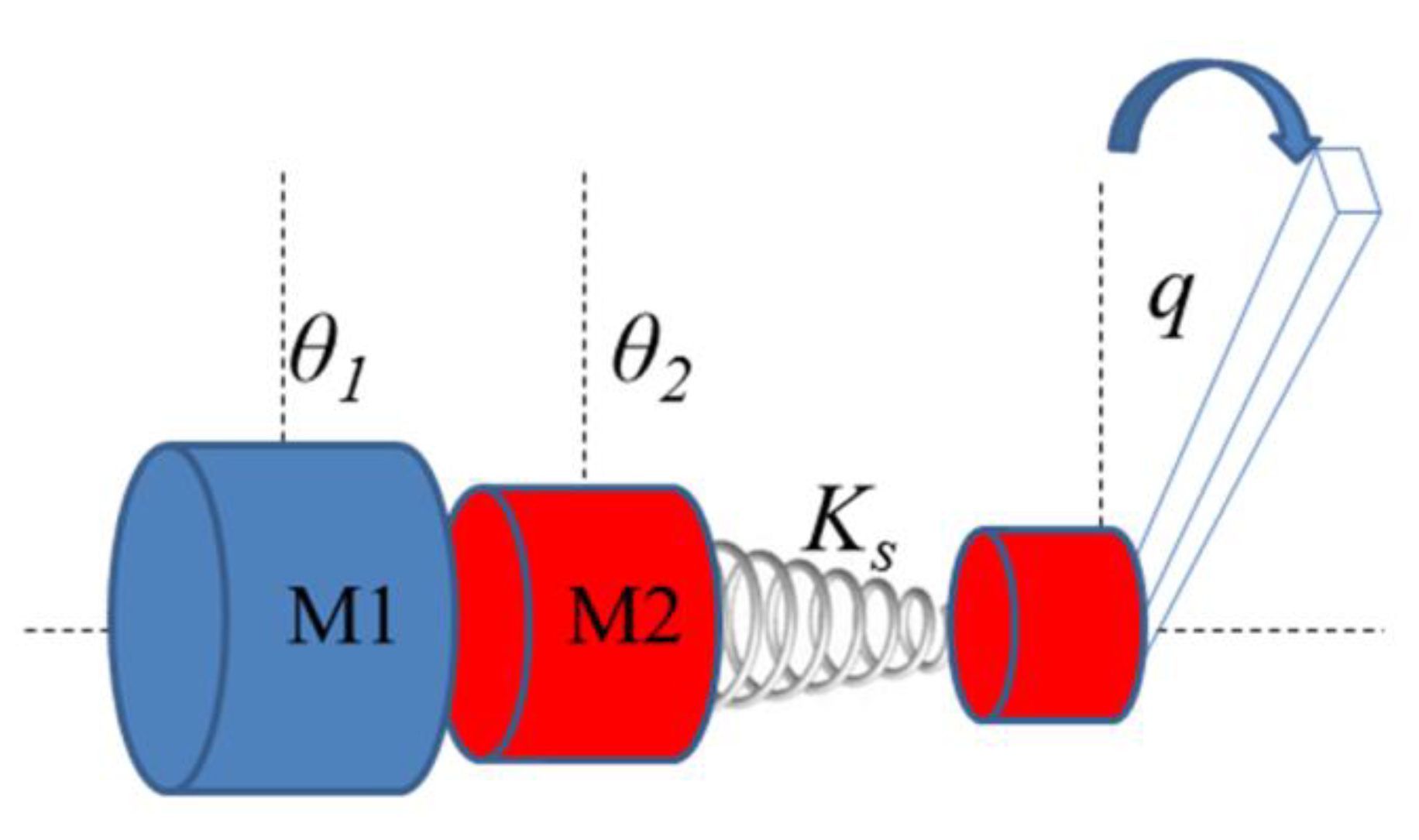
2.2.2. Changing the ratio of a compliant lever (C5)
A compliant lever (Figure 6) has three essential elements: the point where force is applied to the lever, springs and the pivot around which the lever can rotate. The stiffness of the compliant lever can be tuned by changing its ratio, i.e., the relative distance between these three elements, without directly deflecting the springs. Some newly developed VSAs in this class are: the actuator with adjustable stiffness (AwAS-I) [26], (AwAS-II) [27], compact variable stiffness actuator (ComPact-VSA) [28], energy-efficient variable stiffness actuator [29] and variable stiffness actuator, University of Twente [30].
Figure 5.
Series class of stiffness adjustment mechanism based on changing the spring’s deflection.

Figure 6.
Series class of stiffness adjustment mechanism based on changing the spring’s position (lever ratio).
Figure 6.
Series class of stiffness adjustment mechanism based on changing the spring’s position (lever ratio).

3. Performance Analysis
In this section, the stiffness of each SAM is formulated based on the design parameters provided in Table 1. Since the goal of this paper is to analyze and compare the VSA performances in the most generic way possible, some parameters have to be equally set for all different SAMs.
There are some comparison analyses between VSAs in the literature. However, these studies look at individual realization of VSAs rather than the principle of the stiffness regulation behind it. However, in this study, the focus is on the stiffness adjustment mechanism regardless of how this concept has been realized and what types of actuators and transmissions have been employed. This is the main difference between the methods of existing studies and the method used in this work. Therefore, the results of this study are valid for every possible realization of different types of VSAs.
The primary function of a SAM is a channel in which energy can flow between and be distributed among different components of a VSA. From this perspective, the characteristic of a SAM can be defined through its energy-related parameters. The output energy of a SAM is affected by the minimum output stiffness KMin, the maximum output stiffness KMax and the maximum output deflection qMax. This parameters are, in fact, the most essential ones to define the energy characteristics of a SAM. Therefore, in this analysis, KMin, KMax and qMax are set to be 100 (Nm/rad), 1000 (Nm/rad) and 0.2 (rad), respectively. Furthermore, in some cases, the mentioned parameters in Table 1 are not adequate to define the unique performance of a VSA, as other additional parameters are also required. In this case, the performance of the SAM is optimized with respect to those additional parameters.

| Parameter | Description |
|---|---|
| A | Radius of the link’s pulley |
| θ1,2 | Motor position |
| K | Output link stiffness |
| p | Spring’s pretension |
| x | Spring’s deflection |
| Ks | Spring’s constant |
| q | deflection of the output link |
| f(x) | Spring’s force |
To quantify the result of this analysis, a measure α is presented here, which takes into account the stiffness deviation from a pre-set value for a given external load. The imposed external load fext also needs to be set equally for all different classes of SAM. Here, it is assumed that an external load of 20 (Nm) that can deflect the output link to its maximum deflection qMax = 0.2 (rad) at its minimum stiffness KMin = 100 (Nm/rad). Therefore:
and:
![Actuators 03 00270 i001]() where K is the stiffness at the output when it is exposed to a 20 (Nm) load.
where K is the stiffness at the output when it is exposed to a 20 (Nm) load.
fext = KMinqMax

Before going into the details of the calculations, it is important to mention here that these calculations are based on some assumptions:
- (1)
- Only the principle of the mechanisms are considered, regardless of the properties of the actuation unites, e.g., motors and how the principle is realized. Therefore, some actuation-related parameters, such as output power and torque, are not considered in this study.
- (2)
- The work presented here draws upon our previous work on the modeling and stiffness characterization of different SAMs [31].
- (3)
Four types of springs, namely linear, quadratic, exponential and cubic, are considered. The force due to the deflection in each type of spring can be given by:
![Actuators 03 00270 i002]() where Ks denotes the spring’s constant in each type. The stiffness of the spring g(x), which is the derivative of the force f(x) with respect to the spring’s deflection x, is:
where Ks denotes the spring’s constant in each type. The stiffness of the spring g(x), which is the derivative of the force f(x) with respect to the spring’s deflection x, is:
![Actuators 03 00270 i003]()


By knowing the stiffness function K(p), it is possible to calculate the maximum potential energy of the output link for each class and spring. Here, the stiffness function is analyzed for all different classes. It should be mention here that even though the pulley’s radius A appears in the stiffness function in the following formulas, it does not jeopardize the generality of this work, as the energy stored at the output link is independent from A (for more information, please refer to [31]).
3.1. Simple Unidirectional
In the antagonistic design approaches, to change the stiffness, both motors rotate evenly along the directions shown in Figure 2; therefore, θ1 = θ2 = θ. Furthermore, each spring has an initial pretension p when both motors are at rest position θmin = 0. In this case, the link stiffness is denoted as Kp. The springs are considered to be extension nonlinear springs; therefore, the deflection of each spring, x1 and x2, can be expressed as:
x1 = p + θ − Aq
x2 = p + θ + Aq
x2 = p + θ + Aq
Since Springs 1 and 2 are extension springs, when the output link stiffness is at a minimum level Kmin and the link deflection is maximum (q = qmax), the deflection of Spring 1 becomes zero (x1min = 0). Therefore, based on Equation (5), the pretension p is:
p = Aqmax
The torque at the link is given by:
and therefore, the link stiffness at the equilibrium point (q=0) is given by:
![Actuators 03 00270 i004]()
T = A[f(x1) − f(x2]

As is clear, stiffness is a function of pretension p and motor position θ. The pretension can be found based on Equation (6), while to find out the θ, the minimum stiffness Kmin should be considered. The minimum stiffness occurs when both motors are at the zero position (θ1 and θ2 = 0); therefore:
Kmin = Kp
Thus, using Equations (8) and (9), the minimum stiffness of the link is given by:
KMin = 2g(p)A2
Using Equations (6), (8) and (10), the motor position can be expressed based on the link stiffness as:
![Actuators 03 00270 i005]()

3.2. Cross-coupling
In this design, the deflection of each spring is calculated based on Equation (5). In addition, the deflection of Spring 3 (extension) x3 is formulated as:
where p3 is the pretension when both motors are at rest positions. To simplify the analysis, it is assumed that the constant of Spring 3 is the same as the other two. With the motors at the rest position, the net force applied to each motor is zero, and since all of the springs have the same constant, thus their deflection also has to be the same (p3 = p). The stiffness of the link when both motors are at the zero position can be tuned by applying different pretension to Spring 3. Furthermore, in this case, when the link stiffness is minimum (K = KMin) and the link deflection is maximum (q = qMax), the deflection of Spring 1 becomes zero (x1min = 0). Therefore, based on Equation (5), the deflection of the third spring x3 is:
x3 = p3 − 2θ
p = AqMax − θMin
Equations (7) and (8) are valid also in this case; therefore:
Kp = 2g(p)A2
KMin = 2g(AqMax)A2
From Equations (14) and (15), the magnitude of the pretension based on a given value for Kp can be written as:
![Actuators 03 00270 i006]()

Then, based on Equations (8), (13) and (16), the motor positions can be formulated as:
![Actuators 03 00270 i007]()

3.3. Bidirectional
In this case, the deflections of the springs are given by:
where Springs 1 and 2 are connected to Motor 1 and Springs 3 and 4 are attached to Motor 2 in Figure 4. To guarantee bidirectionality, Springs 1 and 4 are extension springs, while Springs 2 and 3 are compression springs. In this case, when the link stiffness is minimum (K = KMin) and the link deflection is maximum (q = qMax), the deflection of Springs 1 and 2 becomes zero (x1min = x2min = 0). Therefore, based on Equation (18), the pretension p is:
x1 = p + θ − Aq
x2 = p + θ − Aq
x3 = p + θ + Aq
x4 = p + θ + Aq
x2 = p + θ − Aq
x3 = p + θ + Aq
x4 = p + θ + Aq
p = Aqmax − θmin
The torque generated by the springs at the joint is:
T = A[f(x1) + f(x2) − f(x3) − f(x4)]
Then, the stiffness at the equilibrium position can be formulated as:
Here, again, like the class of simple antagonistic, by considering Kmin, pretension p and motor position θ can be formulated as functions of link stiffness and deflection [31].
K = 4[q(p + θ)]A2
3.4. Changing pretension of the nonlinear spring
For this type of series class, a simple nonlinear rotary spring placed in series between Motor 1 and the output link is considered. The stiffness is set through changing the angular pretension p of this spring by using Motor 2; thus, p = θ2. At a deflection of the link equal to q, the torque acting on the output link is:
T = T(θ2 + q)
The stiffness of the out link at the equilibrium position is then given as:
where T(θ) and g(θ) are rotary versions of f(x) and g(x) in Equations (2) and (3), respectively.
K = q(θ2)
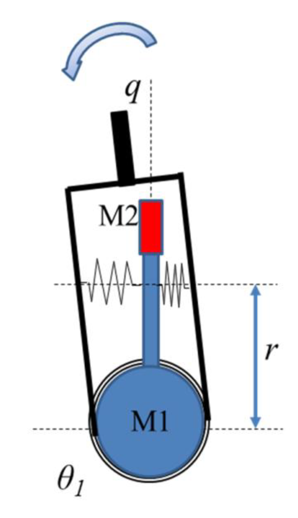
3.5. Changing position of linear spring (lever ratio)
Without loss of generality, here, the focus is on changing the spring’s position. In this type of series class, the distance between the center of rotation of the output link and the point where springs are connected to the shaft of Motor 1 is considered as the lever arm r; Figure 6. The lever arm length is modulated by Motor 2, which is a linear motor; therefore, r = θ2. Springs are inserted with a pretension p. The linear deflection of each spring while the link is deflected as q can be approximated as:
∆x = r sin q
Therefore, the generated torque is:
T = [Ks(p + ∆x) − Ks(p − ∆x)] r cos q = 2Ksr2 sin q cos q
The stiffness of the link at equilibrium position can be calculated as:
or:
![Actuators 03 00270 i008]()
K(r) = 2Ksr2

After formulating the stiffness function, now, the coupling between external force and the stiffness for different types of springs can be found based on Equation (1). It should be mentioned here that all antagonistic classes C1 to C3 and the series class based on changing the spring’s pretension C4 require nonlinear springs in order to change the stiffness. However, the class C5 employs a linear spring for stiffness adjustment.
4. Results and Discussion
The coupling between external force and the stiffness can then be calculated using Equation (2), for each class of SAM and type of spring. The results are shown in Table 2. As the table shows, the intra-class differences are significant compared to the inter-class differences. This means that the spring type plays an important role in coupling/decoupling the external force from the stiffness. In this regard, quadratic springs can totally decouple the stiffness from the load in antagonistic classes. This makes them promising VSA candidates for applications requiring force/impedance control. However, if the same VSA is utilized by exponential springs, the stiffness would strongly couple with the external force. In this case, it would be difficult to consider the actuator as a VSA, since the unintentionally changes in the stiffness due to the external force occur in a far larger scale than can be controlled through the actuation unit. In the class C3, this stiffness deviation is so large that it actually hits the limit of KMax = 1000 (Nm/rad), as the output link is exposed to the external load of 20 (Nm). Cubic springs, however, show noticeable coupling between the load and stiffness in antagonistic classes. In the class C4, where stiffness is tuned by changing the spring’s pretension, quadratic and cubic springs present almost the same coupling, but again, using exponential springs can lead to a high coupling. Finally, the class C5 with a linear spring presents a weak coupling; however, the stiffness is not completely decoupled from the external force.
5. Conclusions
In this paper, coupling between an external force and the stiffness in variable stiffness actuators (VSAs) is analyzed with respect to the type of stiffness adjustment mechanism (SAM) and the nonlinearity of the embedded springs. First, different VSAs were classified based on their SAMs. Then, the level of coupling was calculated through a measure for different classes of SAMs. In the analysis, four different types of spring, linear, quadratic, exponential and cubic, were considered. It was shown that among all different SAM classes and spring types, antagonistic classes with quadratic springs show an absolute decoupling behavior of stiffness from the external load. The high level of decoupling in these classes makes them suitable choices in applications demanding force/impedance
control. The highest level of coupling, however, belongs to antagonistic and series classes, where exponential springs are used. This means that a high amount of energy would be required from the actuation units to compensate for the very large deviations from the pre-set stiffness values as the output link is subjected to any external forces.
Table 2.
Coupling between external force and the stiffness in different stiffness adjustment mechanism (SAM) classes using different types of springs.
| SAM Class | Spring Type | Coupling Measure α |
|---|---|---|
| C1 | quadratic | 0 |
| Exponential | 6.3 | |
| cubic | 0.93 | |
| C2 | quadratic | 0 |
| Exponential | 6.3 | |
| cubic | 0.93 | |
| C3 | quadratic | 0 |
| Exponential | 9 | |
| cubic | 2.32 | |
| C4 | quadratic | 0.76 |
| Exponential | 6.6 | |
| cubic | 0.89 | |
| C5 | linear | 0.21 |
Decoupling between the stiffness and external force is, in fact, a determinant for a VSA. As for future work, other determinants for SAMs, which are more related to the energy efficiency in performing different types of dynamic tasks, will be analyzed.
For instance, one of the critical determinants of SAM is the distribution of its inertia. The performance of the actuator is highly affected, whether SAM adds its inertia to the output link compared to the case where it loads the inertia to the actuation units’ side. Another important factor is how energy can flow within SAM and how it affects the required energy to change into force to maintain the stiffness. Finally, the essential determinant is how compact of a SAM can be realized. In an ideal case, the performance of the SAM should be independent of its size; therefore, it can be implemented in any actuator. That would highly enhance the range of suitable applications for the actuator.
Acknowledgment
This work is supported by the Science and Engineering Research Council, Agency for Science, Technology and Research (A*STAR) under SERC Grant No.: 12251 00007
Conflicts of interest
The author declare no conflict of interest
References
- Pratt, G.A. Series Elastic Actuators. In Proceedings of the IEEE/RSJ International Conference on Human Robot Interaction and Cooperative Robotss, Pittsburgh, PA, USA, 5–9 August 1995.
- Vanderborght, B.; Verrelst, B.; Van Ham, R. Development of a Compliance Controller to Reduce Energy Consumption for Bipedal Robots. Auton. Robot. 2008, 15, 419–434. [Google Scholar] [CrossRef]
- Stramigioli, S.; Van Oort, G.; Dertien, E. A concept for a new energy efficient variable stiffness actuator. In Proceedings of the 2008 IEEE/ASME International Conference on Advanced Intelligent Mechatronics, Xi’an, China, 2–5 July 2008; pp. 671–675.
- Cherelle, P.; Matthys, A.; Grosu, V.; Brackx, B.; Van Damme, M.; Vanderborght, B. Design of the amp-foot 2.0: An active trans-tibial prosthesis that mimics able-bodied ankle behaviour. In Proceedings of the 2nd Joint International Conference on Multibody System Dynamics, Stuttgart, Germany, 29 May–1 June 2010.
- Bureau, M.; Keller, T.; Perry, J.; Velik, R.; Veneman, J. Passive Multirate Wave Communications for Haptic Interaction in Slow VirtualEnvironments. In Proceedings of the 2011 IEEE International Conference on Rehabilitation Robotics (ICORR), Zurich, Switzerland, 29 June–1 July 2011; pp. 1–4.
- Beyl, P.; Cherelle, P.; Kanepen, K.; Lefebder, D. A proof-of-concept exoskeleton for robot assisted rehabilitation of gait. In Proceedings of IFMBE 4th European Conference of the International Federation for Medical and Biological Engineering; Springer: Berlin, Heidelberg, Germany, 2009; pp. 1825–1829. [Google Scholar]
- Alaimo, S.; Pollini, L.; Bresciani, J.-P.; Bulthoff, H. Evaluation of Direct and Indirect Haptic Aiding in an Obstacle Avoidance Task for Tele-operated Systems. In Proceedings of the IFAC World Congress, Milano, Italy, 28 August–2 September 2011.
- Catalano, M.; Griolo, G.; Garabini, M.; Bonomo, F.; Mancinit, M.; Tsagarakis, N.; Bicchi, A. Vsa-cubebot: A modular variable stiffness platform for multiple degrees of freedom robots. In Proceedings of the 2011 IEEE International Conference on Robotics and Automation (ICRA), Shanghai, China, 9–13 May 2011; pp. 5090–5095.
- Yang, C.; Ganesh, G.; Haddadin, S.; Parusel, S.; Abu-Shaeffer, A.; Burdet, E. Human-like adaptation of force and impedance in stable and unstable interactions. IEEE Trans. Robot. 2011, 27, 918–930. [Google Scholar] [CrossRef]
- Garabibi, M.; Passagila, A.; Belo, F.; Salaris, P.; Bicchi, A. Optimality principles in stiffness control: The vsa kick. In Proceedings of the 2011 IEEE International Conference on Robotics and Automation (ICRA), Shanghai, China, 9–13 May 2011; pp. 3341–3346.
- Li, Z.; Tsagarakis, N.; Caldwell, D. A passivity based admittance control for stabilizing the compliant humanoid COMAN. In Proceedings of the 2012 IEEE-RAS International Conference on Humanoid Robots, Osaka, Japan, 29 November–1 December 2012; pp. 44–49.
- Migliore, S.; Brown, E.; DeWeerth, S. Biologically inspired joint stiffness control. In Proceedings of the 2005 IEEE International Conference on Robotics and Automation (ICRA), Barcelona, Spain, 18–22 April 2005; pp. 4508–4513.
- Hurst, J.; Chestnutt, J.E.; Rizzi, A. The actuator with mechanically adjustable series compliance. IEEE Trans. Robot. 2010, 26, 597–606. [Google Scholar] [CrossRef]
- Darden, F. Conception and Realization of Pleated Pneumatic Artificial Muscles and their Use as Compliant Actuation Elements. PhD Thesis, Vrije Universiteit Brussel, Brussels, Belgium, 1999. [Google Scholar]
- Bicchi, A.; Tonietti, G.; Schiavi, R. Fast and Soft Tactile [robot arm design] actuator for Machines Interacting with Humans. In Proceedings of the IEEE Technical Exhibition Based Conference on Robotics andAutomation (ICRA), Barcelona, Spain, 2004; pp. 17–18.
- Schiavi, R.; Grioli, G.; Sen, S.; Bicchi, A. Vsa-ii: A novel prototype of variable stiffness actuator for safe and performing robots interacting with humans. In Proceedings of the 2008 IEEE International Conference on Robotics and Automation (ICRA), Pasadena, CA, USA, 19–23 May 2008; pp. 2171–2176.
- Catalano, M.G.; Grioli, G.; Garabini, M.; Bonomo, F.; Mancini, M.; Tsagarakis, N.; Bicchi, A. VSA-CubeBot: A modular variable stiffness platform for multiple degrees of freedom robots. In Proceedings of the IEEE International Conference on Robotics and Automation (ICRA), Shanghai, China, 9–13 May 2011; pp. 4324–4326.
- Petit, F.; Chalon, M.; Friedl, W.; Grebenstein, M.; Abu-Schaeffer, A.; Hirzinger, G. Bidirectional antagonistic variable stiffness actuation: Analysis, design amp; implementation. In Proceedings of the IEEE International Conference on Robotics and Automation (ICRA), Anchorage, AK, USA, 3–7 May 2010; pp. 4189–4198.
- Eiberger, O.; Haddadin, S.; Abu-Schaeffer, A.; Hirzinger, G. On joint design with intrinsic variable compliance: derivation of the DLR QA-Joint. In Proceedings of the IEEE International Conference on Robotics and Automation (ICRA), Anchorage, AK, USA, 3–7 May 2010; pp. 1050–1649.
- Van Ham, R.; Vanderborght, B.; Van Damme, M.; Verrelst, B.; Lefeber, D. Mechanically adjustable and controllable compliance, equilibrium position actuator (MECCEPA). In Proceedings of the IEEE International Conference on Robotics and Automation (ICRA), Orlando, FL, USA, 15–19 May 2006; pp. 2195–2200.
- Vanderborght, B.; Tsagarakis, N.G.; Van Ham, R.; Thorson, I.; Caldwell, D.G. MACCEPA 2.0: Compliant Actuator used for Energy Efficient Hopping Robot Chobin1D. Auton. Robot. 2011, 31, 55–65. [Google Scholar] [CrossRef]
- Wolf, S.; Hirzinger, G. A new variable stiffness designs: Matching requirements of the next robot generation. In Proceedings of the IEEE International Conference on Robotics and Automation (ICRA), Pasadena, CA, USA, 19–23 May 2008; pp. 1741–1746.
- Wolf, S.; Eiberger, O.; Haddadin, S.; Abu-Schaeffer, A.; Hirzinger, G. The DLR FSJ: Energy based design of a variable stiffness joint. In Proceedings of the IEEE International Conference on Robotics and Automation (ICRA), Shanghai, China, 9–13 May 2011; pp. 5082–5089.
- Park, J.J.; Song, J.B.; Kim, H.S. Safe joint mechanism based on passive compliance for collision safety. Lect. Note. Contr. Inform. Sci. 2008, 370, 49–61. [Google Scholar] [CrossRef]
- Park, J.J.; Song, B. Safe joint mechanism using inclined link with springs for collision safety and positioning accuracy of a robot arm. In Proceedings of the IEEE International Conference on Robotics and Automation (ICRA), Anchorage, AK, USA, 3–9 May 2005; pp. 813–818.
- Jafari, A.; Tsagarakis, N.G.; Caldwell, D.G. A Novel Intrinsically Energy Efficient Actuator with Adjustable Stiffness (AwAS). IEEE Trans. Mechatron. 2011, 18, 355–365. [Google Scholar]
- Jafari, A.; Tsagarakis, N.G.; Sardellitti, I.; Caldwell, D.G. A New Actuator with Adjustable Stiffness Based on a Variable Ratio Lever Mechanism (AwAS-II). IEEE Trans. Mechatron. 2012, 19, 55–63. [Google Scholar]
- Tsagarakis, N.; Sardellitti, I.; Caldwell, D. A new Variable Stiffness Actuator (CompACT-VSA); Design and Modeling. In Proceedings of the IEEE International Conference on Intelligent Robotics Systems(IROS), San Francisco, CA, USA, 25–30 September 2011; pp. 378–383.
- Visser, L.C.; Carloni, R.; Stramigioli, S. Energy-Efficient Variable Stiffness Actuators. IEEE Trans. Robot. 2011, 27, 865–875. [Google Scholar] [CrossRef]
- Carloni, R.; Visser, L.C.; Stramigioli, S. Variable Stiffness Actuators: A Port-Based Power-Flow Analysis. IEEE Trans. Robot. 2012, 28, 1–11. [Google Scholar] [CrossRef]
- Jafari, A.; Tsagarakis, N.G.; Sardellitti, I.; Caldwell, D.G. How design can affect the energy required to regulate the stiffness in variable stiffness actuators. In Proceedings of the IEEE International Conference on Robotics and Automation (ICRA), Saint Paul, MN, USA, 14–18 May 2012; pp. 2792–2797.
© 2014 by the authors; licensee MDPI, Basel, Switzerland. This article is an open access article distributed under the terms and conditions of the Creative Commons Attribution license (http://creativecommons.org/licenses/by/3.0/).
Share and Cite
MDPI and ACS Style
Jafari, A. Coupling between the Output Force and Stiffness in Different Variable Stiffness Actuators. Actuators 2014, 3, 270-284. https://doi.org/10.3390/act3030270
AMA Style
Jafari A. Coupling between the Output Force and Stiffness in Different Variable Stiffness Actuators. Actuators. 2014; 3(3):270-284. https://doi.org/10.3390/act3030270
Chicago/Turabian StyleJafari, Amir. 2014. "Coupling between the Output Force and Stiffness in Different Variable Stiffness Actuators" Actuators 3, no. 3: 270-284. https://doi.org/10.3390/act3030270