Comparative Evaluation of Structural Systems for Tapered Tall Buildings

School of Architecture, Yale University, 180 York Street, New Haven, CT 06511, USA
Buildings 2018, 8(8), 108; https://doi.org/10.3390/buildings8080108
Submission received: 15 July 2018
/
Revised: 30 July 2018
/
Accepted: 8 August 2018
/
Published: 13 August 2018
(This article belongs to the Special Issue Sustainable Vertical Urbanism)
Abstract
:Structural efficiency of tapered tall buildings has been well recognized, and many tall buildings of tapered forms have been built throughout the world. Tall buildings are built with an enormous amount of building materials. As one of the most efficient structural forms for tall buildings, the contribution of tapered forms to saving structural materials coming from our limited natural resources could be significant. Structural design of tall buildings is generally governed by lateral stiffness rather than strength. This paper systematically studies the structural efficiency of tapered tall buildings in terms of lateral stiffness. Tall buildings of various heights and angles of taper are designed with different structural systems prevalently used for today’s tall buildings, such as diagrids, braced tubes, and core-outrigger systems. The heights of the studied buildings range from 60 to 100 stories, and the corresponding height-to-width aspect ratios in their non-tapered prismatic forms range from 6.5 to 10.8. The angles of taper studied are 1, 2, and 3 degrees. Gross floor area of each building of the same story height is maintained to be the same regardless of the different angles of taper. Based on design studies, comparative evaluation of the various structural systems for tapered tall buildings is presented.
1. Introduction
Compared with prismatic forms, tapered forms provide many advantageous aspects for structural systems of tall buildings. For today’s very tall buildings built with higher strength structural materials, it is common that lateral-stiffness requirements against wind loads rather than strength govern their structural design [1]. The magnitudes of lateral shear forces and overturning moments due to wind loads become larger toward the base of the building. Consequently, greater lateral stiffness is required at lower levels. Tapered forms provide greater lateral stiffness toward the base because they naturally produce greater structural depths against lateral loads toward the base.
Tapered forms also help reduce wind loads applied to tall buildings. When a building is tapered, the exterior surface area where the wind load is applied is reduced at higher levels, and increased at lower levels. Since wind pressure is slowly increased toward the top and rapidly decreased toward the bottom, the lateral shear forces and overturning moments are decreased as the angle of taper is increased.
For tall buildings, vortex-shedding induced lock-in phenomena often create the most critical structural design conditions [2]. Tapered forms help tall buildings prevent shedding organized alternating vortices, which cause the lock-in conditions, because of the continuously changing plan dimensions over the building height. Therefore, tapered tall buildings are less susceptible to severe across-wind direction vibrations than prismatic tall buildings.
Including structural materials, tall buildings are built with an enormous amount of building materials coming from our limited natural resources. Different from many other building materials, as the building height is increased, the required amount of structural materials to resist lateral loads is increased exponentially instead of linearly due to the “premium for height” [3]. Therefore, it is essential to develop efficient structural systems for tall buildings to save our limited resources and construct more sustainable built environments. At the same time, it is also very important to produce building forms that can contribute to structural efficiency for the same purposes. Tapered forms are inherently one of the most efficient structural forms for tall buildings.
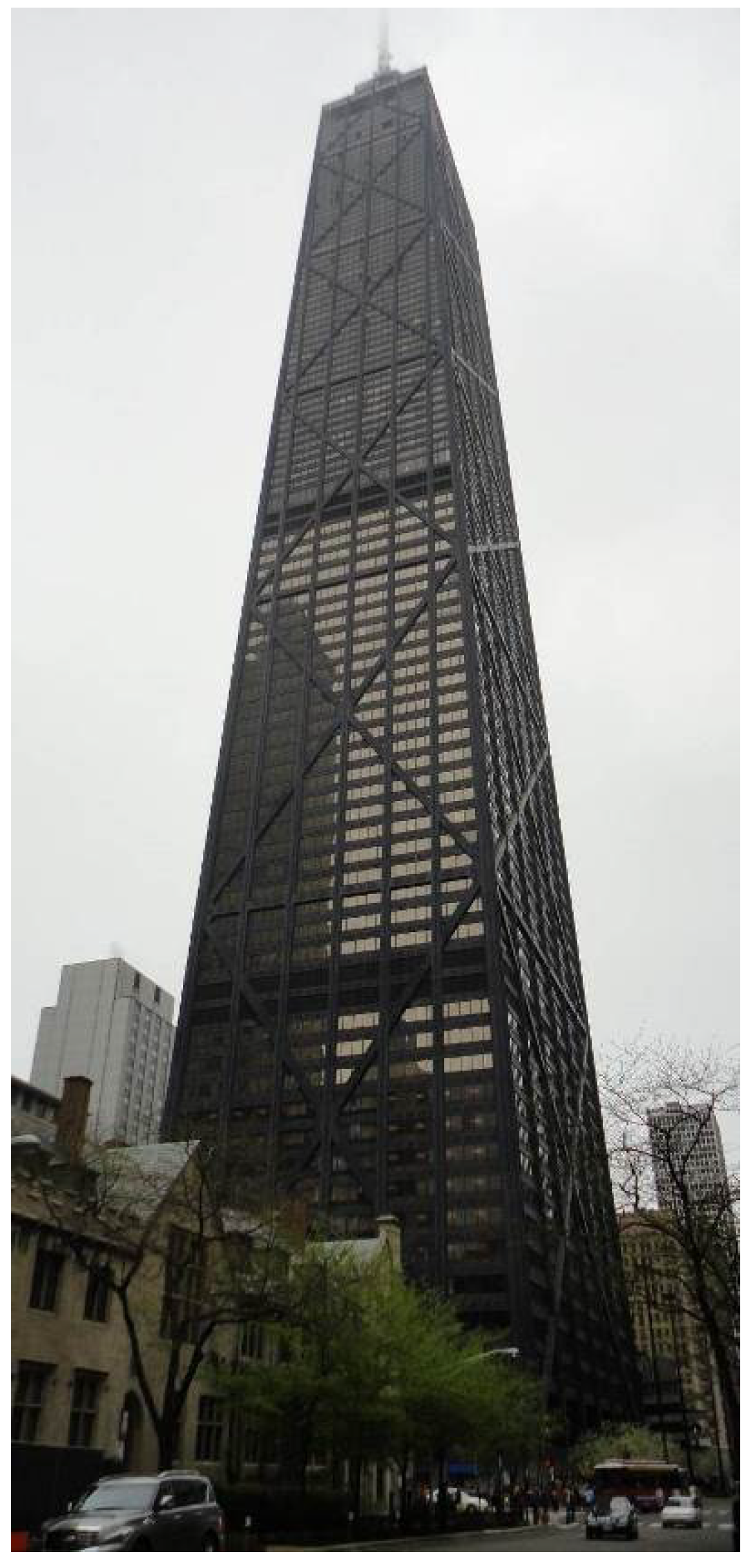
Further, tapered forms are often more desirable architecturally for ever-increasing mixed-use tall buildings. For residential functions in tall buildings, for example, it is important to make living spaces not too far away from natural outdoor environments, including natural light to maximize the occupants’ comfort. For commercial functions, however, this is less important, and deeper rentable spaces are often desired. Therefore, tapered tall buildings, with commercial functions on the lower levels and residential functions on the higher levels, perform very well architecturally. A well-known example of this type of spatial organization in a tapered tall structure can be found in the 100-story tall John Hancock Center (now called 875 North Michigan Avenue) of 1969 in Chicago, designed by Skidmore, Owing, and Merrill (Figure 1).
Among many different aspects of tapered forms, this paper systematically examines comparative efficiency of various structural systems employed for tapered tall buildings, based on lateral stiffness. Tall building structural systems prevalently used today include diagrids, braced tubes, and core-outrigger structures. Tapered tall buildings of 60, 80, and 100 stories are designed with these structural systems and their structural performances are studied comparatively. The corresponding height-to-width aspect ratios of the 60-, 80-, and 100-story tall buildings in their non-tapered prismatic forms are 6.5, 8.7, and 10.8, respectively. The angles of taper studied are 1, 2, and 3 degrees.
2. Tapered Braced Tubes
The braced tube is a very efficient structural system for tall buildings as it carries lateral loads by axial actions of the perimeter tube members. The system was developed in the late 1960s, and applied to major tall buildings, such as the previously introduced John Hancock Center in Chicago, Renaissance Tower in Dallas, and 780 Third Avenue in New York [4]. The braced tube system once led structural expressionism by boldly expressing its primary structural members on the building façades. Though the braced tube members are often hidden behind the façades in today’s tall buildings, the system in its conventional form, more efficiently modified form, or combined form with another system is still widely used due to its inherent structural efficiency.
In order to study the structural performance of tapered forms employed in braced tubes, 60-story buildings of various angles of taper are designed with braced tubes. A non-tapered prismatic braced tube structure is designed first. The building’s typical plan dimensions are 36 m × 36 m with an 18 m × 18 m core at the center, and typical story heights are 3.9 m. The perimeter braced tube system is designed to carry the entire lateral loads, and the core is designed to carry only gravity loads, in order to clearly estimate the impact of taper on the performance of the perimeter braced tube system. The building is assumed to be in Chicago and the ASCE/SEI 7, Minimum Design Loads for Buildings and Other Structures, is used to establish the wind load. Based on the code, the basic wind speed is 90 mph (about 40 m/s). One percent damping is assumed for the calculation of the gust effect factor. This loading condition is used not only for the braced tube but also for the diagrids and core-outrigger structures presented later in this paper.
The vertical perimeter column sizes of the 60-story braced tube structure in terms of their cross-sectional area range from about 2800 cm2 in the lowest module to 80 cm2 in the highest module. The diagonal bracing sizes range from about 980 cm2 to 100 cm2. These braced tube member sizes for the prismatic tower were determined using the stiffness-based design methodology developed by Moon [5] to meet the maximum lateral displacement requirement of a five-hundredth of the building height. A braced tube building is modeled as a cantilever beam, and subdivided longitudinally into modules according to the repetitive pattern. Each module is defined by a single level of diagonals that extend over multiple stories. Figure 2 illustrates a 10-story braced tube module in which V is lateral shear force and M is moment. Lateral stiffness of the braced tube modules can be expressed as shown in Equations (1) and (2).
KT is shear stiffness; KB is bending stiffness; Ad is cross-sectional area of each diagonal; Ac is cross-sectional area of each column; E is modulus of elasticity of steel; θ is angle of diagonal member; Nc,f is number of columns on each flange frame; δ is contribution of web columns for bending stiffness; B is building width in the direction of applied force; h is module height.
The lateral shear stiffness of the braced tube system is primarily governed by the cross-sectional area and angle of the diagonal bracings. However, the impact of the diagonal angle changes caused by tapering the tower by 1, 2, and 3 degrees is minimal. The bending stiffness is governed by the perimeter column size and building width. As the building is tapered, the building width is increased toward the base, where the maximum overturning moment is applied, and consequently the bending stiffness is increased.
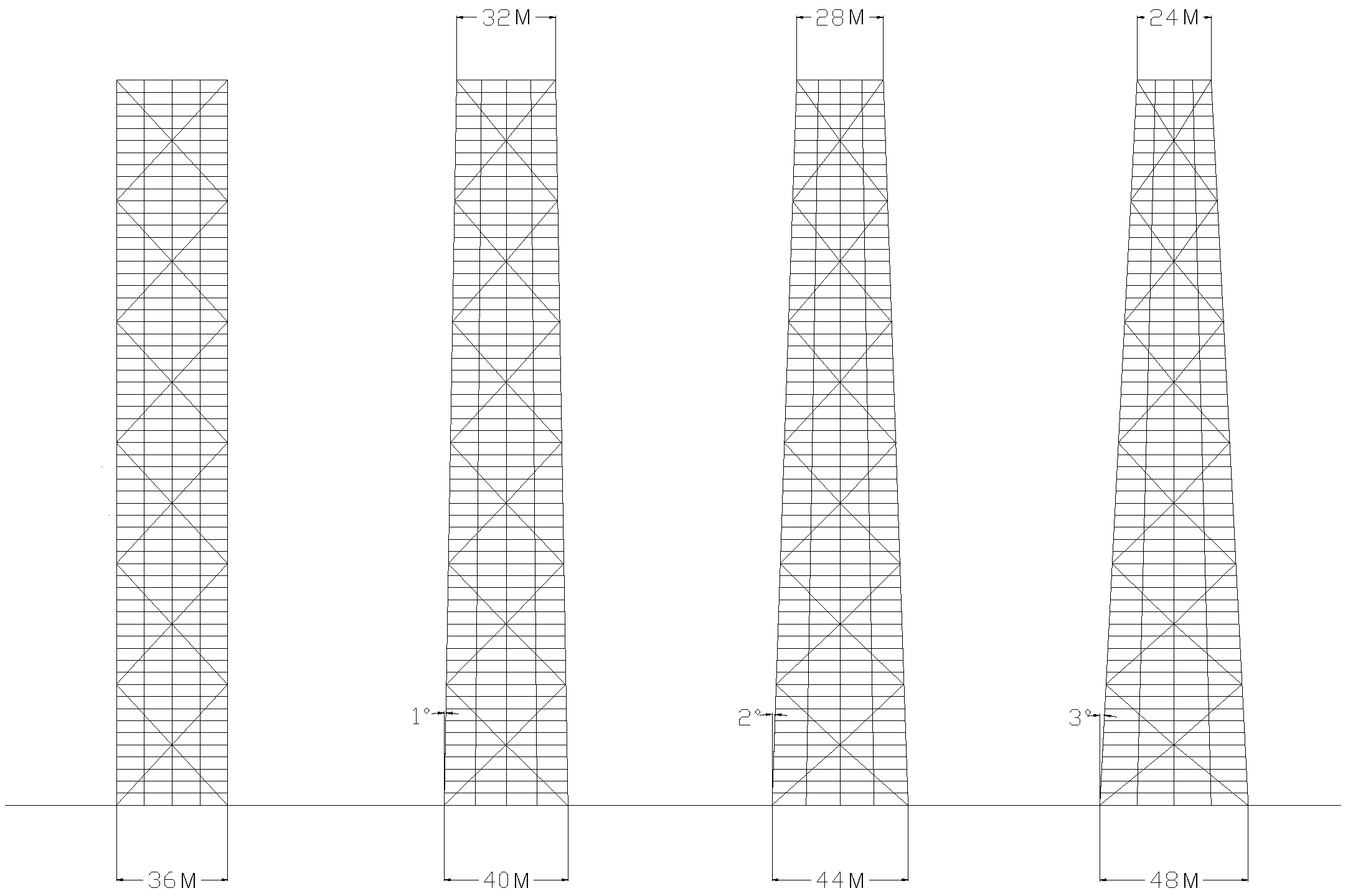
Figure 3 shows the 60-story braced tube structures tapered with three different angles of 1, 2, and 3 degrees. Since the building width at mid-height is maintained to be the same as the original prismatic tower, each tapered building’s gross floor area is the same regardless of the different angles of taper. Member sizes determined for the prismatic braced tube are also used for the tapered ones for preliminary-design purposes to investigate the impact of tapering the structure comparatively.
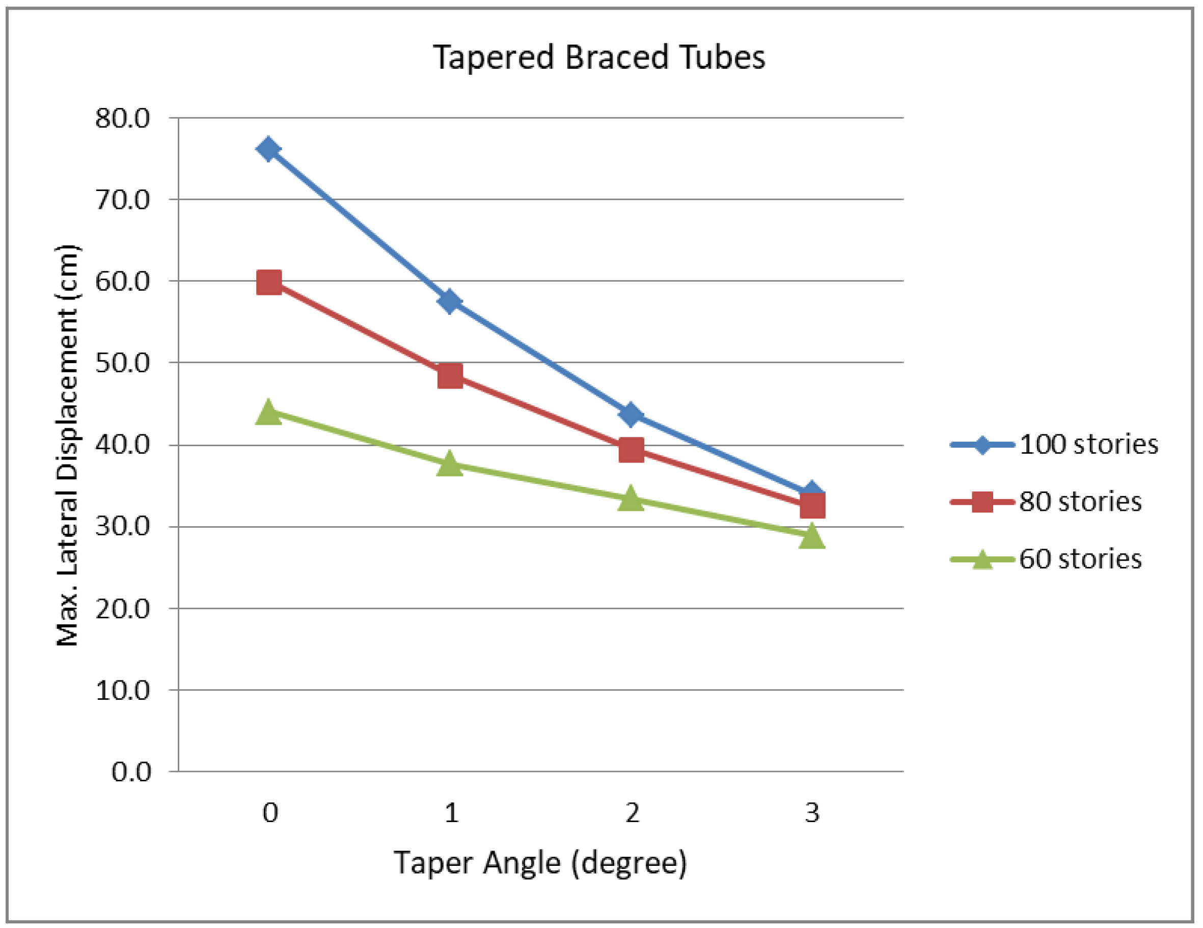
The maximum lateral displacements of the 60-story tapered braced tubes shown in Figure 3, as well as similarly configured and designed 80- and 100-story tapered braced tubes, are summarized in Figure 4 based on SAP2000 analysis results. As has been predicted, lateral stiffness of the braced tube is increased as the angle of taper is increased. Consequently, lateral displacements of tapered braced tubes are reduced as the angle of taper is increased. Further, the rate of displacement reduction due to taper is accelerated as the building becomes taller. The maximum lateral displacement of the 100-story tapered braced tube with its tapered angle of 3 degrees is only about a half of that of the corresponding non-tapered prismatic braced tube of the same height.
3. Tapered Diagrids
Since its application to the 30 St. Mary Axe (also known as the Swiss Re Building) of 2004 in London and Hearst Tower of 2006 in New York (Figure 5), both by Norman Foster, the diagrid system has widely been used for contemporary tall buildings throughout the world, including the 103-story tall Guangzhou International Finance Center, the tallest diagrid building at present. Diagrid structures carry lateral loads very efficiently by axial actions of the perimeter diagonal grid members. When the system is employed for tapered tall buildings, its lateral stiffness can be further increased. A most notable tapered diagrid structure can be found in the unbuilt 112-story Lotte Super Tower project for Seoul by Skidmore, Owing, and Merrill.
As another tube-type structure with perimeter diagonals, the structural performance of diagrids is similar to that of the braced tubes. However, unlike previously studied braced tube structures, which are composed of vertical columns and diagonal bracing members, diagrid structures are composed of only diagonal gird members. As the angle of diagrids on the flange planes (planes perpendicular to winds) of the building becomes steeper, greater bending stiffness is obtained against overturning moments. However, as the diagrid angle becomes steeper on the web planes (planes parallel to winds), shear stiffness of the system is reduced. Since winds can blow in any direction, the angle of diagrid members should carefully be determined to carry both overturning moments and lateral shear forces effectively. Considering that the best angle for bending as well as gravity is 90 degrees, and that for lateral shear is about 35 degrees, measured from the horizontal [5], it can be predicted that the optimal angle of diagrid members is between these two angles. As a building becomes taller and slenderer, its structure tends to behave more like a vertical cantilever bending beam, and, consequently, the optimal angle becomes steeper. As a building becomes shorter, its structure tends to behave more like a shear beam and the optimal angle becomes shallower. Thus, the optimal angle of diagrid members should be determined based on the height and height-to-width aspect ratio of the building.
Diagrids being a tube-type structure like braced tubes, it can be predicted that their lateral stiffness is increased as the tapered angle is increased. It can also be predicted that the impact of taper on bending stiffness becomes larger as the building becomes taller. However, these issues cannot be considered separately from the angle of diagrid members, which is a more fundamental stiffness-determining factor. As a prismatic diagrid tall building with diagonals placed at a uniform angle is tapered, the angle of diagrid members is changed along the height of the building. When the same diagrid module height is used throughout the building, as the building is tapered, the angle of diagrid members becomes steeper toward the top and shallower toward the base. This angle configuration contributes to reducing the lateral stiffness of the diagrid system because it reverses structural logic. In tall buildings, the lower and upper portions tend to be governed by overturning moments and lateral shear forces, respectively. Therefore, in varying angle situations, the angles should be appropriately steeper toward the base and shallower toward the top. Thus, adjustments are required and these issues can be better investigated with design studies.
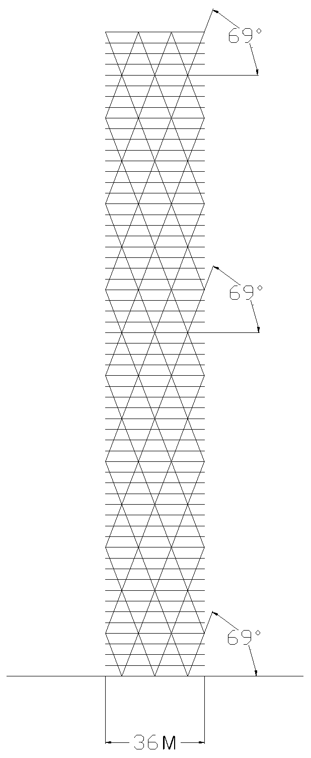
Sixty-story buildings of various angles of taper are designed with diagrids. A non-tapered prismatic diagrid structure is designed first. The prismatic building’s typical plan dimensions are 36 m × 36 m with an 18 m × 18 m core at the center, and typical story heights are 3.9 m, which results in a height-to-width aspect ratio of about 6.5. The perimeter diagrid system is designed to carry the entire lateral loads, and the core is designed to carry only gravity loads in order to clearly estimate the impact of taper on the performance of the perimeter diagrids. Three diamond-shaped submodules of the diagrids are placed within the building width of 36 m. Preliminary studies suggest that a configuration with a diagrid module height of eight stories, which results in a diagrid angle of 69 degrees, as shown in Figure 6, is the near-optimal condition.
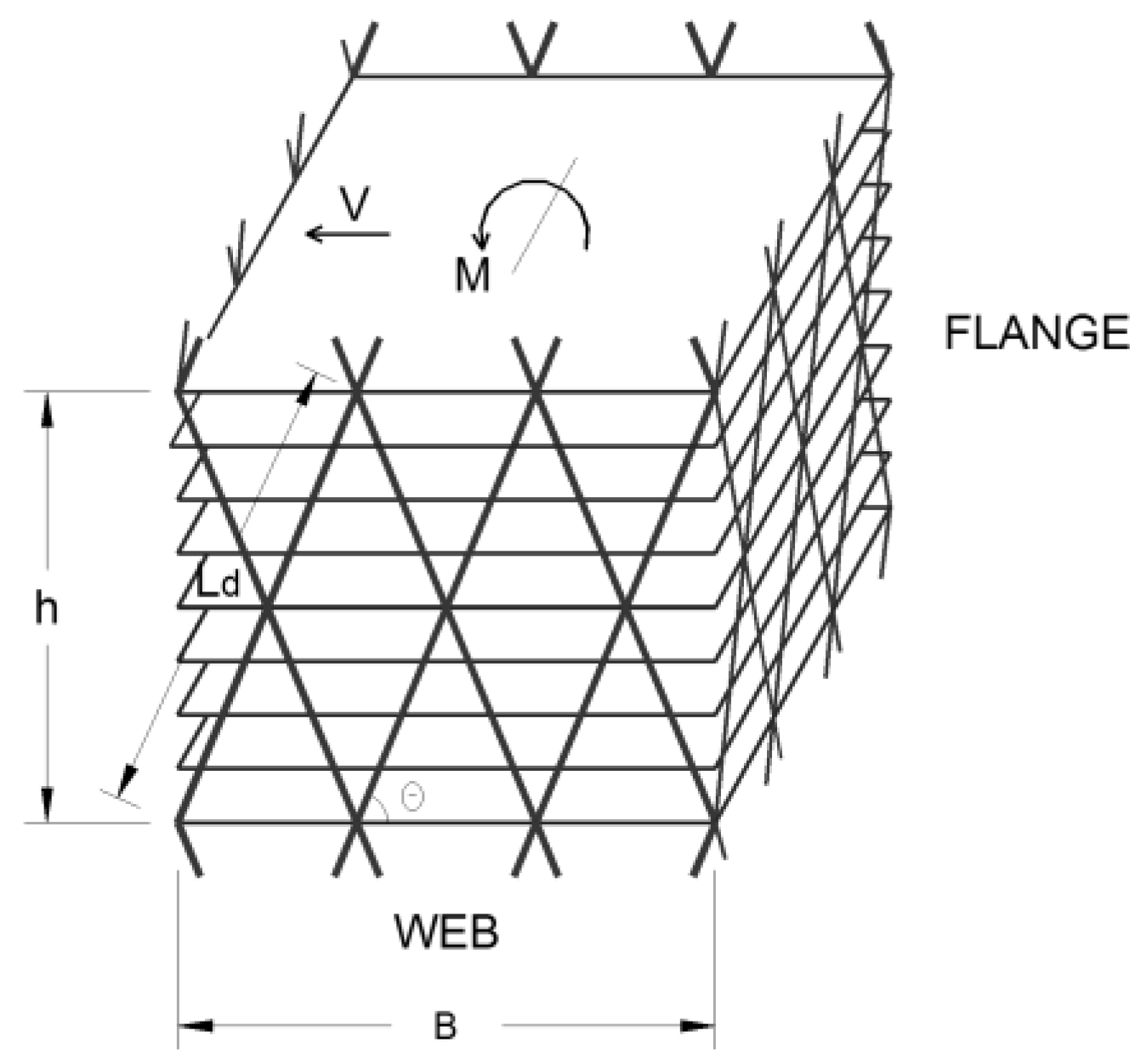
The perimeter diagonal sizes of the 60-story diagrid structure in terms of their cross-sectional area range from about 2000 cm2 in the lowest module to 80 cm2 in the highest module. These diagrid member sizes for the prismatic tower were determined with the stiffness-based design methodology developed by Moon [6] to satisfy the maximum lateral displacement requirement of a five-hundredth of the building height. A diagrid structure is modeled as a cantilever beam, and subdivided longitudinally into modules according to the repetitive diagonal pattern. Each module is defined by a single level of diagonals that extend over multiple stories. Figure 7 illustrates an eight-story diagrid module in which V is lateral shear force and M is moment. Lateral stiffness of the diagrid modules can be expressed as shown in Equations (3) and (4).
KT is shear stiffness; KB is bending stiffness; Ad,w is cross-sectional area of each diagonal on web planes; Ad,f is cross-sectional area of each diagonal on flange planes; E is modulus of elasticity of steel; θ is angle of diagonal member; B is building width; Ld is length of diagonal; Nd,w is number of diagonals on each web plane; Nd,f is number of diagonals on each flange plane.
The lateral shear stiffness of the diagrids is primarily governed by the cross-sectional area and angle of the diagonals. The bending stiffness is governed by the cross-sectional area and angle of the diagonals as well as building width. As the building is tapered, the building width is increased toward the base where the maximum overturning moment is applied. Consequently, the bending stiffness in relation to the building width is increased in tapered diagrids. The more complicated impact of diagrid angle changes due to tapering on lateral shear and bending stiffness is further discussed in more detail in what follows with design-study models.
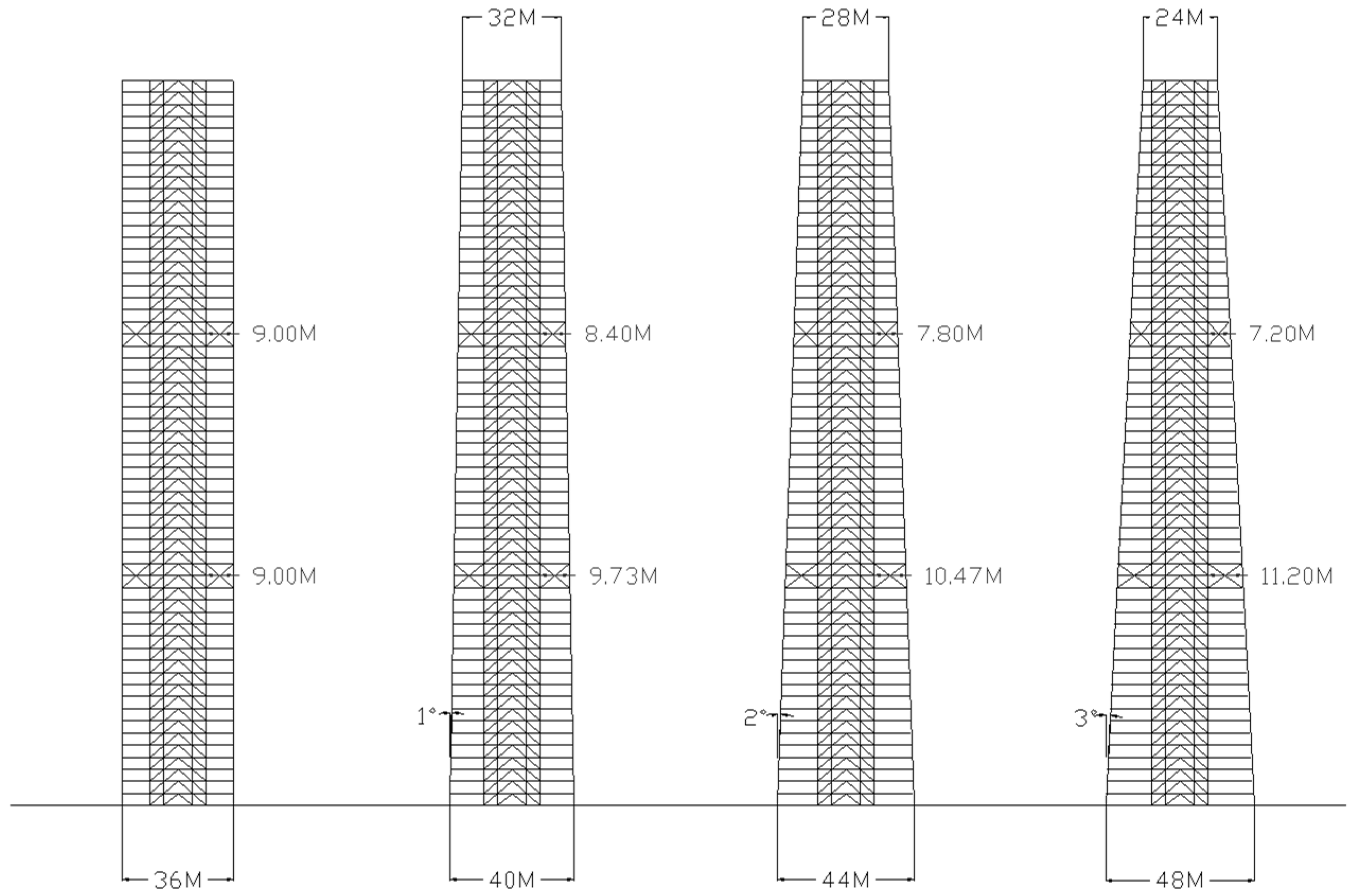
Figure 8a shows the 60-story diagrid structures tapered with three different angles of 1, 2, and 3 degrees. Since the building width at mid-height is maintained to be the same, each building’s gross floor area is the same regardless of the different angles of taper. Member sizes determined for the prismatic diagrids are also used for the tapered diagrids for preliminary design purposes to investigate the impact of tapering the structure comparatively.
As has been discussed, a very important design issue associated with tapering the diagrid towers is that, if the module height and the number of the diamond-shaped submodules within the building width are maintained to be the same regardless of the different angles of taper, the diagrid angles become steeper at higher levels, and shallower at lower levels in the tapered diagrid structures, as can be seen in Figure 8a (Alt. 1). As briefly discussed earlier, studies suggest that varying-angle diagrid structures with diagrid members placed at angles shallower toward the base are less efficient than optimal uniform-angle diagrid structures for tall buildings. Further, varying-angle diagrid structures with diagrid members placed at angles appropriately steeper toward the base could be more efficient for very tall buildings because taller structures behave more like bending beams and diagrid members placed at steeper angles at lower levels provide higher bending rigidity [7,8]. Thus, the tapered diagrid structures shown in Figure 8a are adjusted into two different angle configurations by changing the module heights. Figure 8b (Alt. 2) shows a group of adjusted diagrid structures with diagrid members placed at angles close to the optimal uniform angle throughout the building height. Figure 8c (Alt. 3) shows another group of adjusted diagrid structures with diagrid members placed at angles steeper toward the base of the buildings.
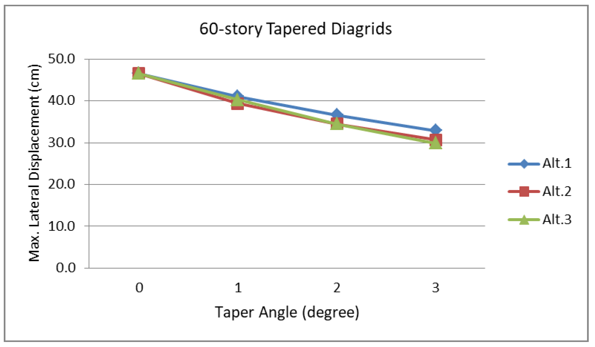
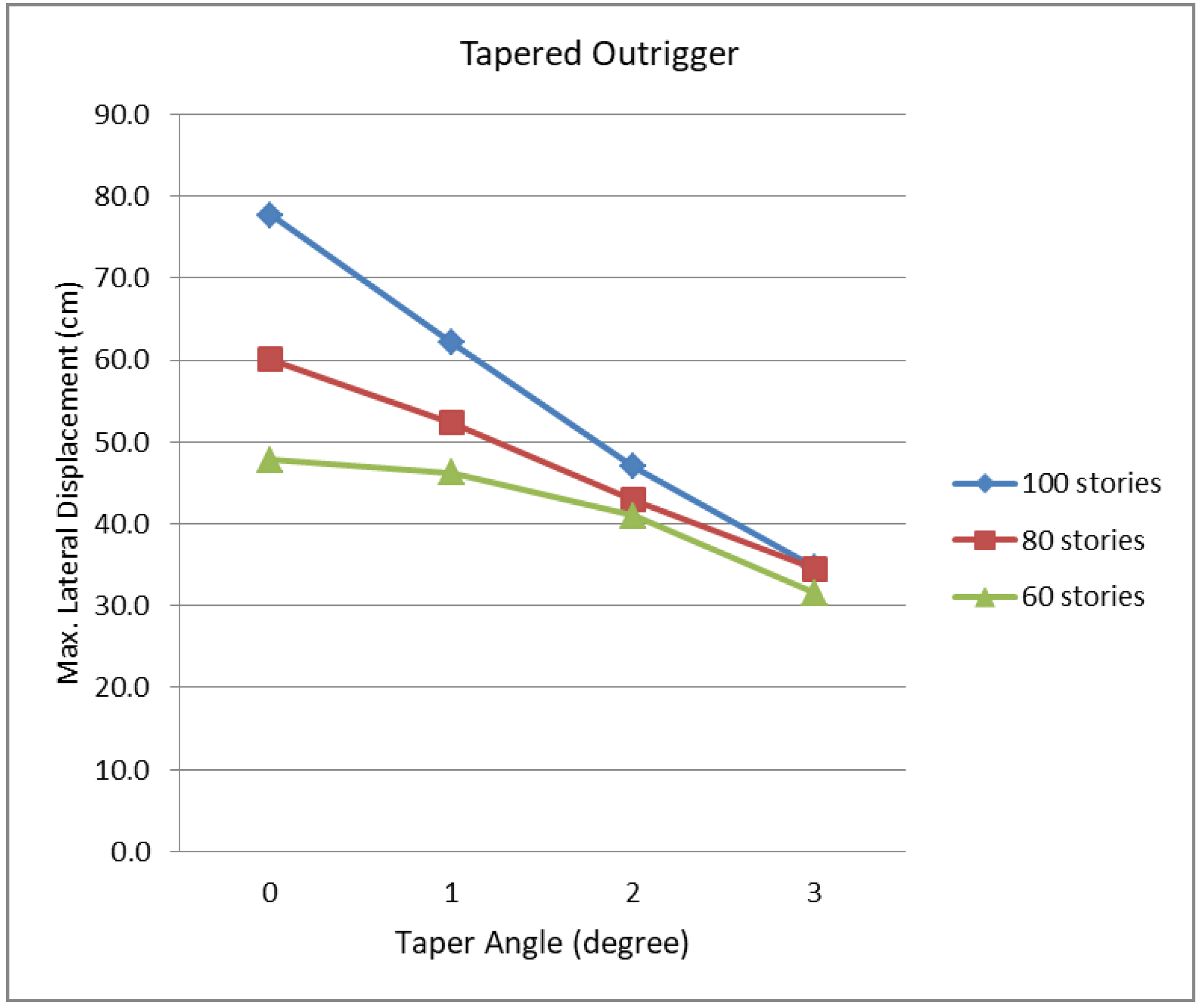
Figure 9 summarizes the maximum lateral displacements of the 60-story tapered diagrid structures shown in Figure 8a–c. As the angle of taper is increased, the lateral stiffness of the diagrid structures is increased. Consequently, the maximum lateral displacements of the tapered diagrid structures are decreased substantially. Once the angles of the diagrid members are adjusted to be close to the optimal uniform angle (Alt. 2) or to be steeper toward the base (Alt. 3), the lateral stiffness of the tapered diagrid structures is further increased. The maximum lateral displacements of Alt. 2 and Alt. 3-type diagrid structures of the same angle of taper are very similar for the 60-story structures.
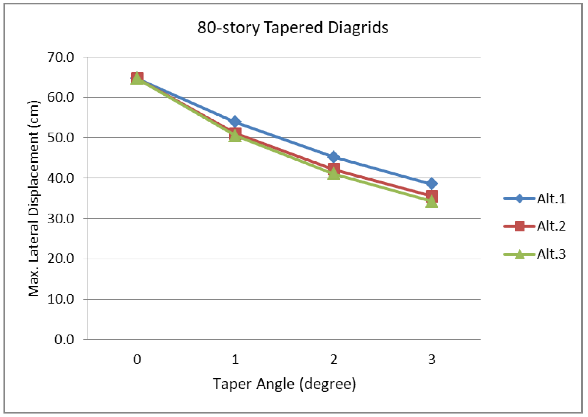
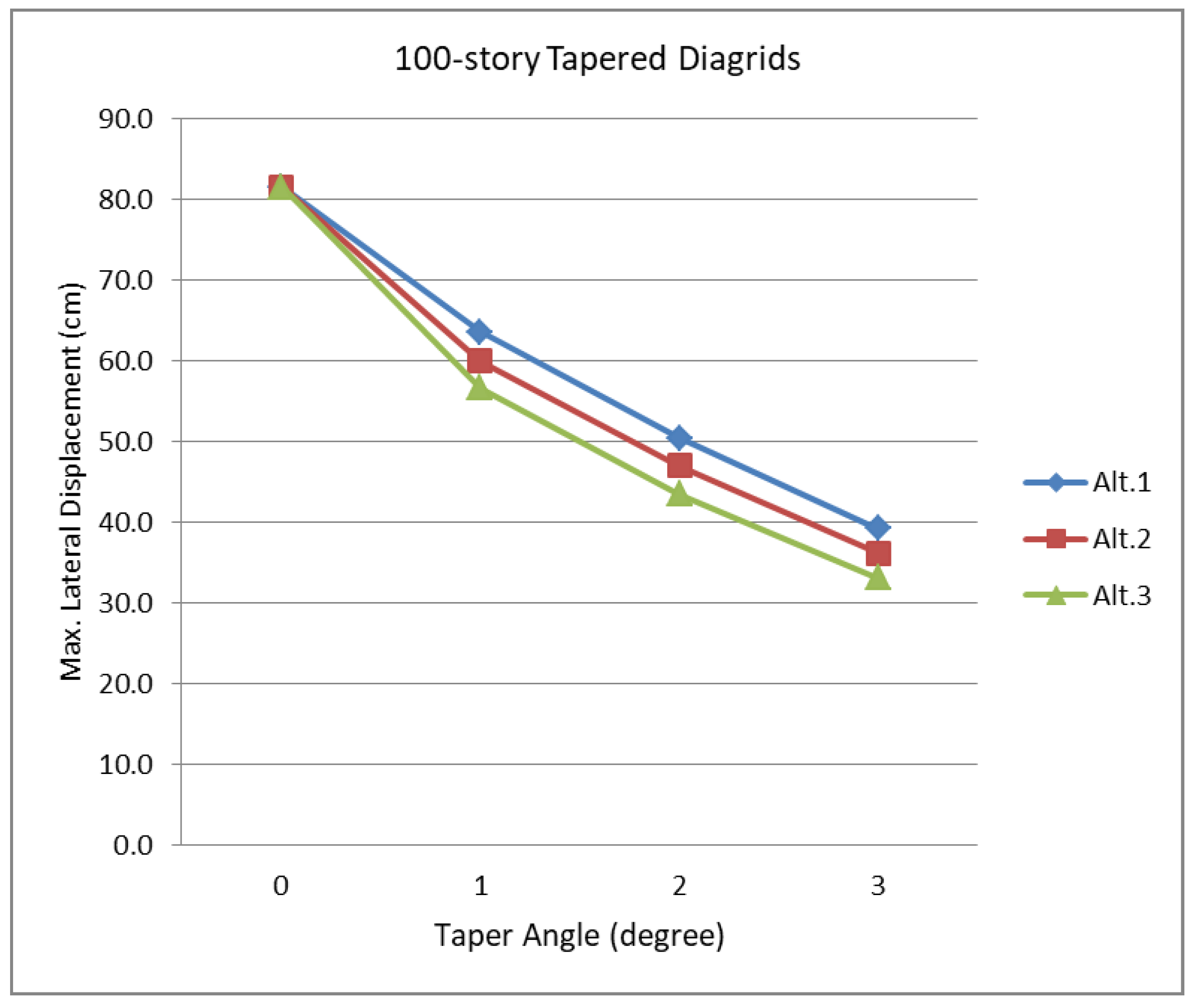
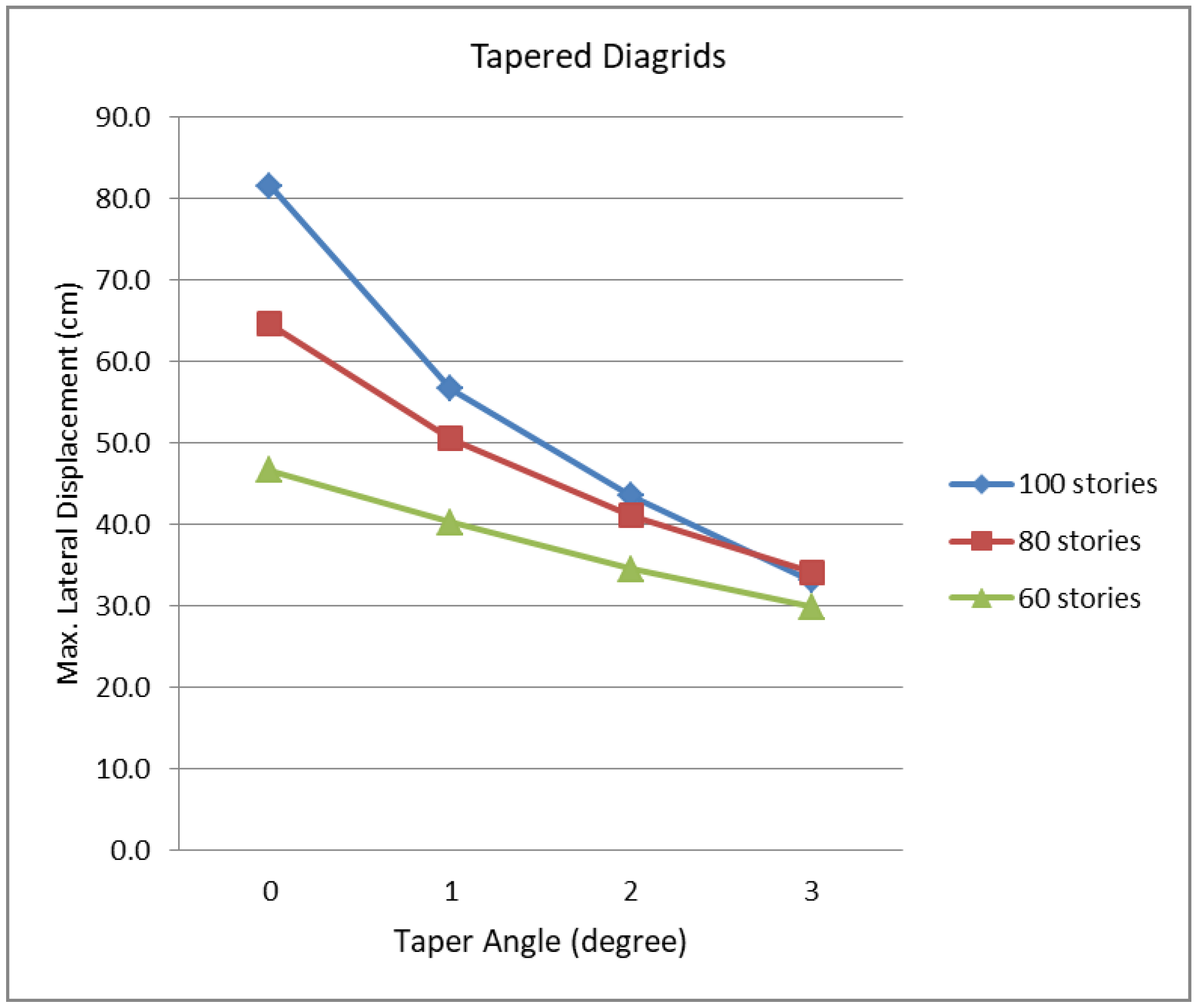
Similar studies are repeated for the 80- and 100-story diagrid structures, and the results are summarized in Figure 10 and Figure 11, respectively. In terms of reducing lateral displacements, the impact of taper becomes greater as the structure becomes taller. The stiffness increase based on the diagrid angle adjustments also becomes greater as the structure becomes taller. For the 80-story buildings, Alt. 3-type diagrid structures, with diagrid members placed at angles steeper toward the base, produce noticeably less lateral displacements than Alt. 2 type, with diagrid members placed at angles close to the optimal uniform angle. For the 100-story buildings, Alt. 3-type diagrid structures result in even more substantially increased lateral stiffness and reduced lateral displacements compared to Alt. 2 type.
Figure 12 summarizes the maximum lateral displacements of the 60-, 80- and 100-story tapered diagrids of the Alt. 3 type. It clearly shows that the impact of taper becomes greater as the diagrid structure becomes taller. Further, it is also clear that the increased lateral stiffness due to the diagrid angle adjustments is accelerated as the building becomes taller. The maximum lateral displacement of the 100-story tapered diagrid structure with its tapered angle of 3 degrees combined with the logical diagrid angle adjustment is only about 40% of that of the corresponding non-tapered prismatic diagrids of the same height.
4. Tapered Core-Outrigger Structures
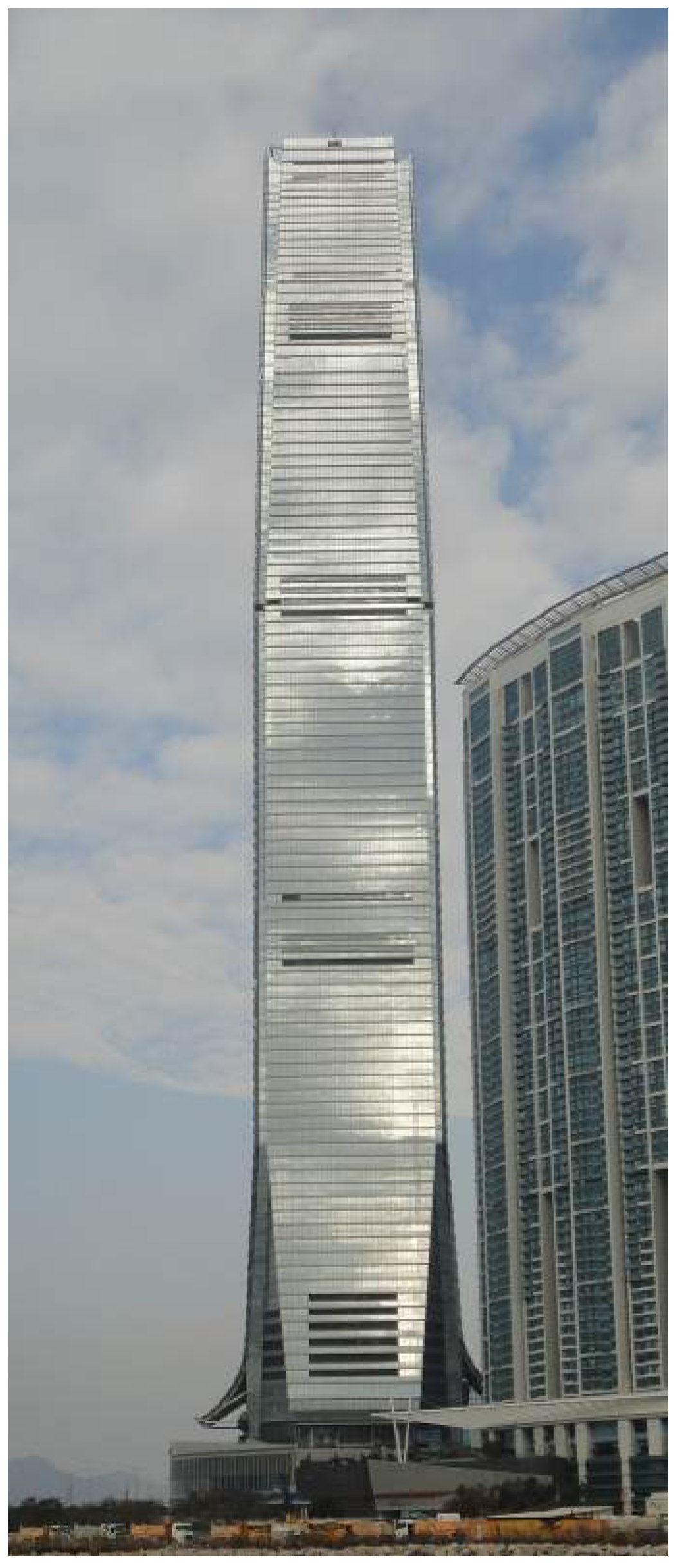
Core-outrigger structures are another very efficient and prevalently used structural system for today’s tall buildings. While an early example of the core-outrigger structures can be found in the Place Victoria Building (now called Stock Exchange Tower) of 1964 in Montreal, a major application of this type of structural system is on contemporary tall buildings, such as the Jin Mao Tower in Shanghai, Taipei 101 in Taipei, International Commerce Center in Hong Kong (Figure 13), and Shanghai Tower in Shanghai, the tallest core-outrigger structure at present, to name but a few [9].
In the braced tube and diagrid systems, lateral shear forces and overturning moments are primarily carried by perimeter tube members, which are often expressed on the building façades (Figure 1 and Figure 5). In the core-outrigger system, lateral shear forces are carried primarily by the interior core structure, and overturning moments are carried by the core structure as well as perimeter megacolumns connected to the core through outrigger trusses (or outrigger walls). Consequently, façades of tall buildings with core-outrigger structures can be designed with more flexibility.
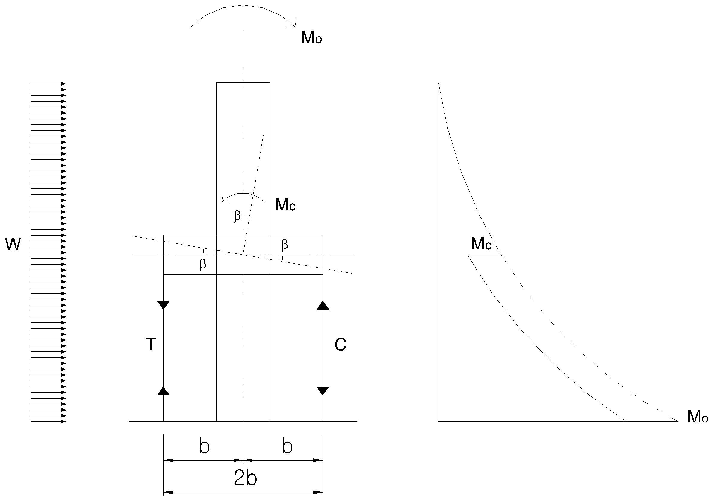
The core-outrigger system’s lateral load-carrying mechanism is conceptually explained in Figure 14. The overturning moment (Mo) caused by wind loads (W) is reduced due to the counteracting moment (Mc) provided by the megacolumns. The counteracting moment Mc can be expressed in terms of the building width and cross-sectional area of the megacolumns.
A is the cross-sectional area of the megacolumns; b is the distance between the center of the core and perimeter megacolumns on the outrigger plane; E is the modulus of elasticity of steel; and χ is the curvature of the structure as a vertical cantilever bending beam.
In steel structures, since the modulus of elasticity of steel is constant regardless of its strength, the outrigger structure’s bending stiffness is a function of the square of the distance between the center of the core and perimeter megacolumns as well as cross-sectional area of the megacolumns. In a tapered tall building structured with the outrigger system having sloped perimeter megacolumns following the overall tapered building form, the distance between the core and megacolumns is continuously increased toward the base and consequently the system’s bending stiffness is increased.
Sixty-story buildings of various angles of taper are now designed with core-outrigger systems. A non-tapered prismatic core-outrigger building is designed first. The prismatic building’s typical plan dimensions are 36 m × 36 m, with typical story heights of 3.9 m. An 18 m × 18 m core structure at the center is now designed with braced frames to carry not only gravity but also lateral loads. It is noted that the cores for the previously studied braced tube and diagrid structures were designed to carry only gravity loads. The core in the outrigger system is connected to the perimeter megacolumns through outrigger trusses located at one-third and two-thirds of the height of the building. Other design conditions, including the wind load and the maximum allowable lateral displacement, are the same as before. The lateral bending stiffness between the building core and megacolumns is carefully distributed for optimal performance. Based on preliminary studies on the optimal stiffness distribution, the core is designed to provide about 40 percent of the lateral bending stiffness and the megacolumns are designed to provide the rest. With this stiffness distribution, the sizes of the megacolumns of the 60-story outrigger structure in terms of their cross-sectional area are about 4100 cm2 between the ground and lower outrigger trusses and 1900 cm2 between the lower and upper outrigger trusses.
The core-outrigger structure is then tapered with three different angles of 1, 2, and 3 degrees, as shown in Figure 15. Since the building width at mid-height is maintained to be the same as the original prismatic tower, each building’s gross floor area is the same regardless of the different angles of taper. By tapering the tower, the distances between the opposite-side perimeter megacolumns, which act as counteracting overturning moment arms, become greater toward the base, where greater overturning moments are developed, and narrower toward the top. This configuration helps increase the lateral stiffness of the system. While the overall building form is tapered, the central braced core that houses elevators, stairs, ducts, etc. is not tapered in this study. Therefore, the length of the outrigger trusses that connect the central braced core and perimeter megacolumns is changed accordingly. The length of the outrigger trusses becomes longer toward the base of the building as the angle of taper is increased. In core-outrigger structures with multiple outriggers, the lowest outrigger induces the maximum resisting moment and the outriggers above carry successively less [10,11]. The increased length of the lower outrigger trusses reduces the stiffness of the trusses and consequently adversely contributes to increasing the lateral stiffness of the tapered core-outrigger system. However, the increased stiffness based on tapering the structure still governs the overall performance of the system.
The maximum lateral displacements of the 60-story tapered outrigger structures shown in Figure 15, as well as similarly configured and designed 80- and 100-story tapered outrigger structures, are summarized in Figure 16. Lateral displacements of core-outrigger structures are reduced as the angle of taper is increased. The detailed characteristics of the displacement reduction based on taper in core-outrigger structures are a bit different from those in diagrids and braced tubes due to the different structural configuration of the system, while the overall performance characteristics are still very similar. The lateral stiffness of the tapered core-outrigger structures can be further increased by increasing the stiffness of the outrigger trusses, especially those on lower levels.
5. Conclusions
This paper studied structural performances of braced tubes, diagrids, and core-outrigger structures employed for tapered tall buildings. Structural design of tall buildings is generally governed by lateral stiffness, and tapered forms help increase lateral stiffness and reduce lateral loads. The lateral performance characteristics of tapered perimeter-tube-type structures, such as diagrids and braced tubes, are very similar, while those of tapered core-outrigger structures are a bit different because of the different structural configuration. Nonetheless, all the systems designed with tapered forms produce superior structural performances than those with non-tapered prismatic forms.
Studies performed in this paper were limited to the static responses of tapered tall building structures. In tall buildings, vortex shedding induced across-wind responses, which could involve resonances, often create the most critical structural design conditions. Vortex-shedding frequency is directly related to wind velocity, Strouhal number, and plan dimensions of the building. Thus, tapered forms with continuously changing plan dimensions also help tall buildings prevent shedding organized alternating vortices over the building height. Therefore, tapered forms provide superior static as well as dynamic wind responses for tall building structures.
Tall buildings are built with an enormous amount of building materials coming from our limited natural resources. Different from many other building materials, the required amount of structural materials to resist lateral loads increases exponentially due to the “premium for height” as a building becomes taller. The contribution of tapered forms as one of the most efficient structural forms for tall buildings to saving our limited resources and consequently constructing more sustainable built environments can be significant.
Tall buildings were originally developed as office towers in the late 19th century. Today, however, tall buildings are designed for various other functions, including residential functions. Tapered forms can be very effective not only structurally but also architecturally for mixed-use tall buildings containing both commercial and residential functions, in terms of adjusting floor depths to satisfy different design requirements.
Today’s diversity in architectural design has produced many different building forms. Tapered forms have widely been used for tall buildings due to their many inherent advantageous characteristics, including those discussed in this paper. Exploring and investigating further potentials of tapered forms as well as various other non-prismatic building forms, such as twisted, tiled, and irregular free forms can lead to constructing better-performing and more sustainable higher-quality built environments.
Funding
This research received no external funding.
Conflicts of Interest
The author declares no conflicts of interest.
References
- Connor, J.J. Introduction to Structural Motion Control; Prentice Hall: New York, NY, USA, 2003. [Google Scholar]
- Simiu, E.; Scanlan, R.H. Wind Effects on Structures: Fundamentals and Applications to Design, 3rd ed.; Wiley: New York, NY, USA, 1996. [Google Scholar]
- Ali, M.M.; Moon, K. Structural Developments in Tall Buildings: Currents Trends and Future Prospects. Archit. Sci. Rev. 2007, 50, 205–223. [Google Scholar] [CrossRef]
- Kowalczyk, R.; Sinn, R.; Kilmister, M.B. Structural Systems for Tall Buildings. Council on Tall Buildings and Urban Habitat Monograph; McGraw-Hill: New York, NY, USA, 1995. [Google Scholar]
- Moon, K. Stiffness-Based Design Methodology for Steel Braced Tube Structures: A Sustainable Approach. Eng. Struct. 2010, 32, 3163–3170. [Google Scholar] [CrossRef]
- Moon, K.; Connor, J.J.; Fernandez, J.E. Diagrid Structural Systems for Tall Buildings: Characteristics and Methodology for Preliminary Design. Struct. Des. Tall Spec. Build. 2007, 16, 205–230. [Google Scholar] [CrossRef]
- Moon, K. Optimal Grid Geometry of Diagrid Structures for Tall Buildings. Archit. Sci. Rev. 2008, 51, 239–251. [Google Scholar] [CrossRef]
- Baker, W.F.; Besjak, C.M.; McElhatten, B.J.; Biswas, P. 555 m Tall Lotte Super Tower, Seoul, South Korea. In Proceedings of the Structures Congress, Austin, TX, USA, 30 April–2 May 2009. [Google Scholar]
- Choi, H.; Ho, G.; Joseph, L.; Mathias, N. Outrigger Design for High-Rise Buildings: An Output of the CTBUH Outrigger Working Group, 2nd ed.; Council on Tall Buildings and Urban Habitat: Chicago, IL, USA, 2017. [Google Scholar]
- Smith, B.; Coull, A. Tall Building Structures: Analysis and Design; Wiley: New York, NY, USA, 1991. [Google Scholar]
- Taranath, B. Steel, Concrete, & Composite Design of Tall Buildings; McGraw-Hill: New York, NY, USA, 1998. [Google Scholar]
Figure 1.
John Hancock Center in Chicago (Photograph by Kyoung Sun Moon).

Figure 2.
10-story braced tube module.
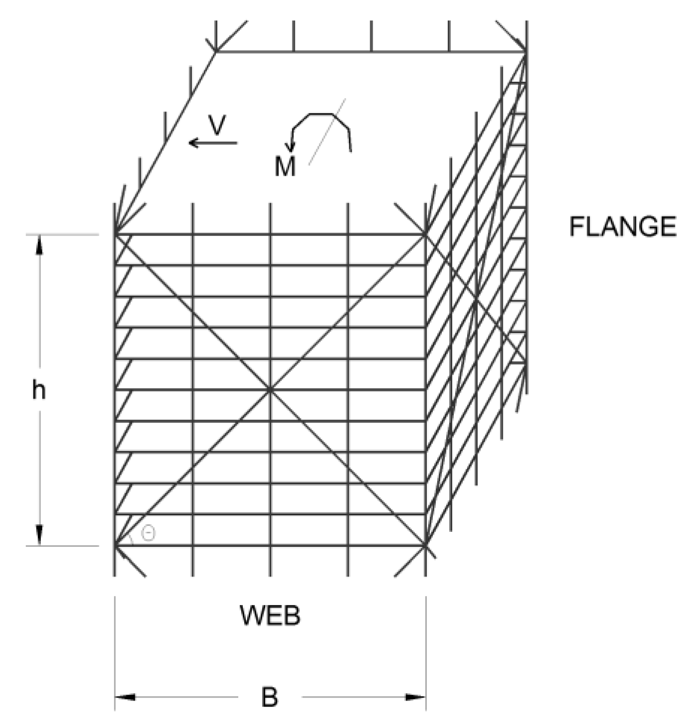
Figure 3.
60-story tapered braced tubes.

Figure 4.
Maximum lateral displacements of the 60-, 80-, and 100-story tapered braced tubes.

Figure 5.
Hearst Tower in New York (photograph by Kyoung Sun Moon).
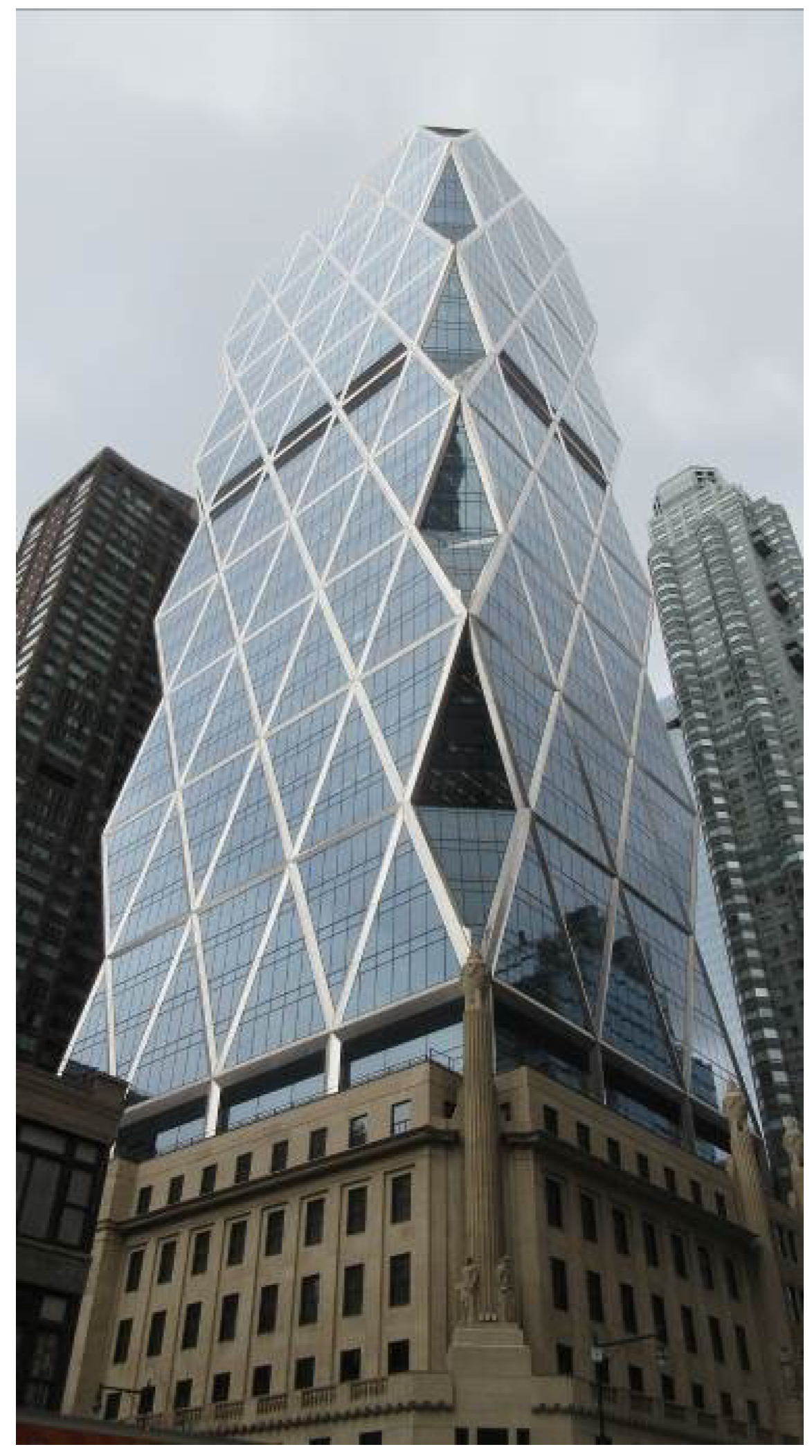
Figure 6.
60-story diagrid structure.

Figure 7.
Eight-story diagrid module.

Figure 8.
60-story tapered diagrids design.
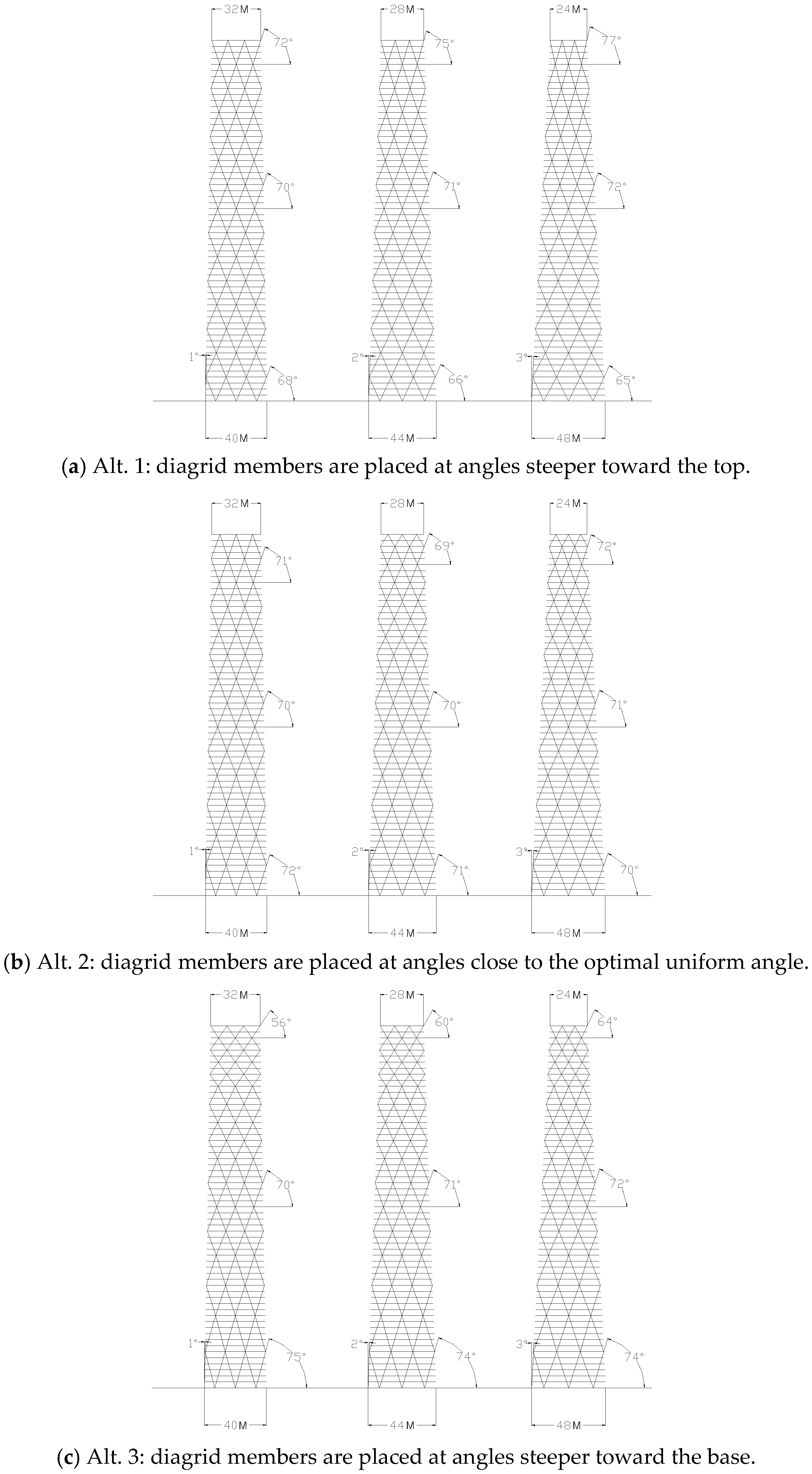
Figure 9.
Maximum lateral displacements of the 60-story tapered diagrids shown in Figure 8a–c.
Figure 9.
Maximum lateral displacements of the 60-story tapered diagrids shown in Figure 8a–c.

Figure 10.
Maximum lateral displacements of the 80-story tapered diagrids.

Figure 11.
Maximum lateral displacements of the 100-story tapered diagrids.

Figure 12.
Maximum lateral displacements of the 60-, 80-, and 100-story tapered diagrids.

Figure 13.
International Commerce Center in Hong Kong (photograph by Kyoung Sun Moon).

Figure 14.
Structural concept of core-outrigger system.

Figure 15.
60-story tapered core-outrigger structures.

Figure 16.
Maximum lateral displacements of the 60-, 80-, and 100-story tapered core-outrigger structures.
Figure 16.
Maximum lateral displacements of the 60-, 80-, and 100-story tapered core-outrigger structures.

© 2018 by the author. Licensee MDPI, Basel, Switzerland. This article is an open access article distributed under the terms and conditions of the Creative Commons Attribution (CC BY) license (http://creativecommons.org/licenses/by/4.0/).
Share and Cite
MDPI and ACS Style
Moon, K.S. Comparative Evaluation of Structural Systems for Tapered Tall Buildings. Buildings 2018, 8, 108. https://doi.org/10.3390/buildings8080108
AMA Style
Moon KS. Comparative Evaluation of Structural Systems for Tapered Tall Buildings. Buildings. 2018; 8(8):108. https://doi.org/10.3390/buildings8080108
Chicago/Turabian StyleMoon, Kyoung Sun. 2018. "Comparative Evaluation of Structural Systems for Tapered Tall Buildings" Buildings 8, no. 8: 108. https://doi.org/10.3390/buildings8080108
Note that from the first issue of 2016, this journal uses article numbers instead of page numbers. See further details here.