A Semantics-Rich Information Technology Architecture for Smart Buildings

Abstract
:
1. Introduction
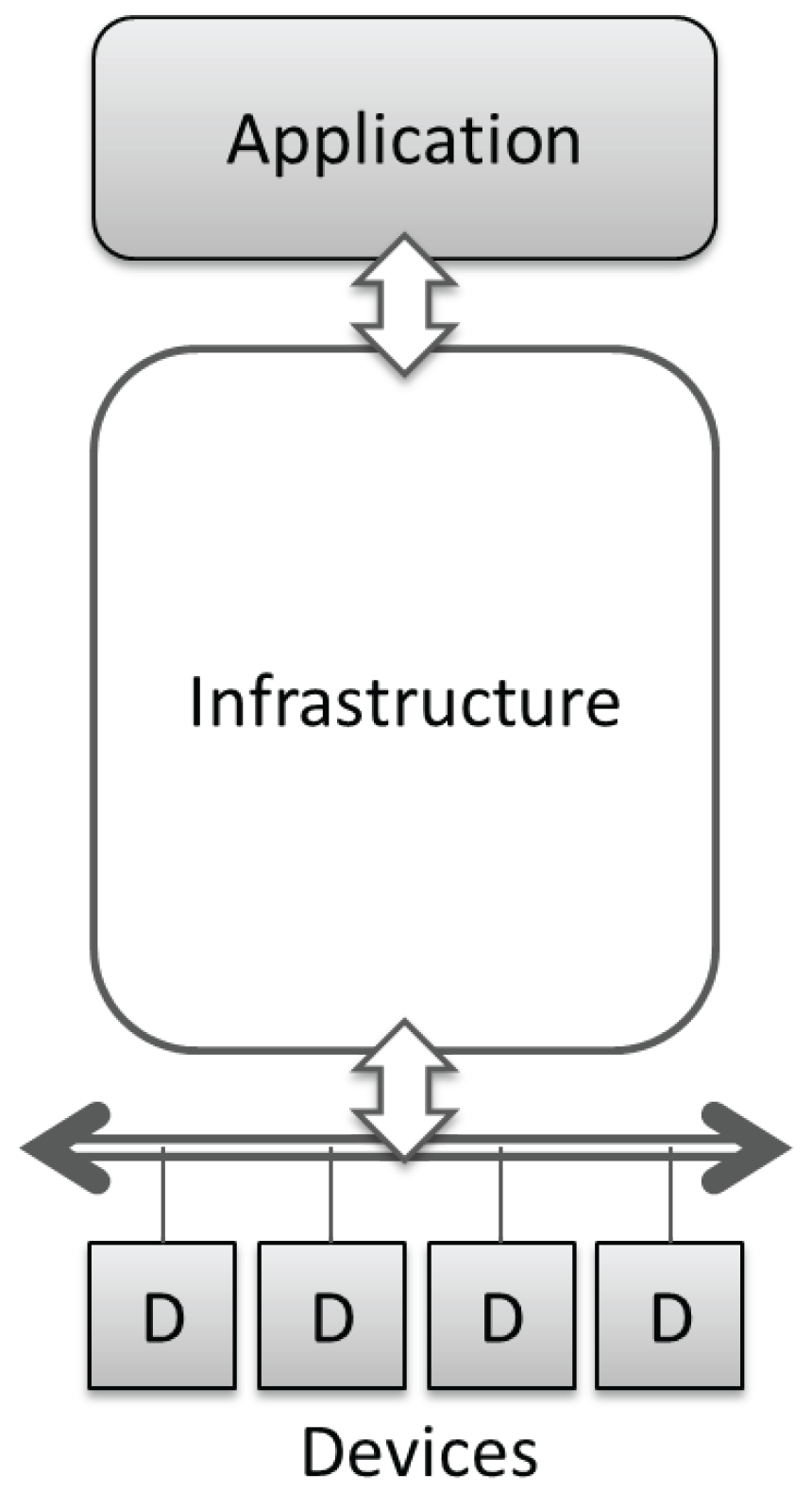
2. Horizontal Architectures
2.1. Common Approaches
- Creation of dashboards representing either the real-time situation or some overall performance indicator computed from current and past data observations. Such dashboards may be public or reserved to building managers. These are adopted mostly as a monitoring tool.
- Detection and handling of alarms (anomalous combinations of values, trespassing of thresholds, etc.) by constantly monitoring the systems and relaying the time- and security- or safety-critical information to the responsible person(s).
- Ability of remotely controlling some aspects of the system (such as operating actuators, activating or de-activating some automatic behaviors, adjusting some operational set-points, etc.) by means of a suitable user interface.
- Collection, storage and query of historical data, used as the consolidated basis of a comprehensive data set allowing more complex elaborations and analysis.
- Deep off-line analysis of the stored data, in order to extract trends, compare the performance in different periods and, more generally, define and compute sets of KPIs (key performance indicators) of interest to the system stakeholders. In some limited cases, computation may also involve real-time data (e.g., for threshold checking against historical averages), but it mostly consists of business intelligence methods applied to historical data sequences.
- On-line real-time computation of derived quantities [3]: in some cases, storing data and later elaborating it might waste resources (e.g., bandwidth from the building site to the cloud data center) and introduce unacceptable latency (e.g., for alarm management). In such cases, the on-site system will be required to compute some result, in real time, operating on fresh data: such computations might be simple (e.g., time averages, filtering outlier measurements, summing up the contributions of different sensors) or more complex (involving computation of derivatives, integrals, the application of dynamic models or the emulation of virtual sensors).
- Finally, we should realize that a BMS could fruitfully exchange data with other information systems at the enterprise level, for example with ERP (Enterprise resource planning) systems for managing energy costs and billing [7] or with logistics software to get the expected occupation of building spaces. Such integration is usually a strong driver, which might justify the return on the investment of a BMS in the first place.
- The main driver behind the design of the communication infrastructure is, quite naturally, the technology chosen for field devices; see the relevant description below.
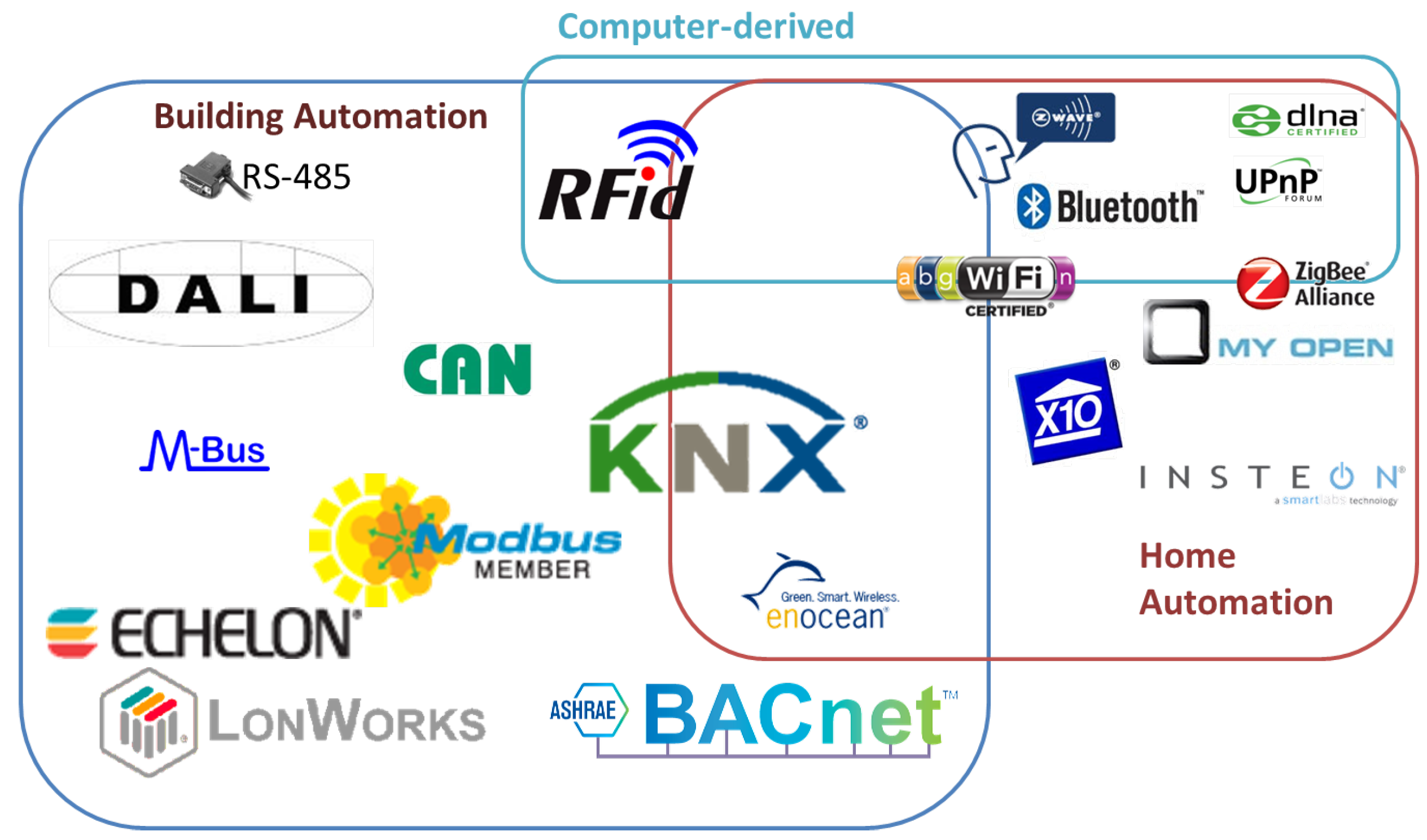
- The infrastructure is mainly identified by the communication protocols that are adopted; in fact, in many cases, protocols, devices and infrastructure are so intertwined that their choice must be joint. Such protocols may be derived from field-bus standards, from Internet standards or from wireless network solutions; in the worst cases, there may be legacy or proprietary protocols to be integrated in the infrastructures.
- Different design choices are also influenced by the scale of the installation: in fact, while the focus of the paper is on buildings, the same technologies and architectures may scale from very local solutions (e.g., houses), to wider and/or geographic-scale settings (buildings, sets of buildings, up to neighborhoods or smart city or transport systems).
- Related to the scale issue, also the number of devices may impact the choice of the infrastructure, both due to the maximum number of supported devices by each technology and due to the involved bandwidth necessary to transfer all needed data to and from all installed devices.
- The needed bandwidth is also influenced by the required sampling frequency: such frequency usually stems from application-level requirements (e.g., energy management systems usually work on a 15-min time scale, while automation and control should react in sub-second time) and is limited by the transmission capability of the chosen infrastructure (e.g., the transfer rate of long serial lines or the power saving needs of wireless sensors).
- An additional responsibility of the infrastructure layer is the enforcement of system security, by granting suitable authorizations to properly authenticated users and applications, only. When dealing with field-buses, which are a classically closed and independent system, this issue was marginal, but when the systems are being integrated and being exposed to the Internet, such concerns become very demanding: the press constantly reports new home automation devices that can be hacked very easily.
- Depending on the type of devices and on the application requirements, the type of data being transferred may vary significantly: from simple Boolean variables or flags (e.g., in control systems), to real-valued physical measurements (e.g., temperature, humidity), to multimedia content (e.g., ambient sounds, environment images).
- The previous issue must be coupled with the problem of data encoding, which should guarantee that data is interpreted consistently by all involved devices and applications.
- Concerning the communication patterns, some simpler infrastructure technologies support a master-slave polling method, only, where the application must constantly and periodically query all sensors and devices. Conversely, more advanced infrastructures support the concept of time-driven or event-driven transmission, where devices may be pushing information to the application autonomously, as soon as new or updated information is available.

- environment sensors, for sensing and measuring some physical property of a portion of the environment (temperature, humidity, , pollutants, illumination, wind, etc.);
- user sensors, for sensing and measuring some actions and conditions related to the usage of the building by users (presence, movement, access control, etc.);
- energy measurement devices (electrical energy, electrical power, more advanced electrical network properties, consumptions of gas, water, oil and other materials, etc.);
- actuators (relays, electro-valves, motors, lights, dimmers, etc.).
2.2. Common Approaches Pitfalls
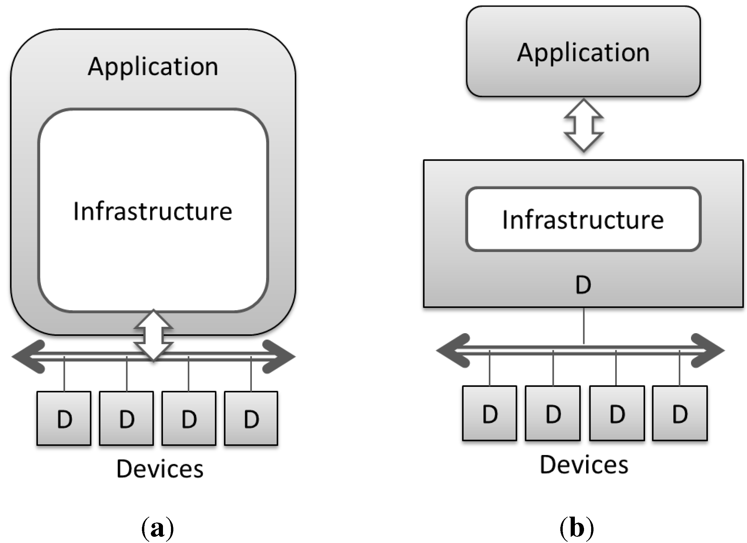
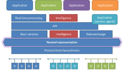
- “All you can eat” application (shown in Figure 3a). In this case, the infrastructure level has been “eaten” by the application layer. In other words, the additional complexity described above has been dealt with directly by the final applications. This approach, usually taken by system integrators or software-oriented companies, effectively solves the problems with a relatively moderate cost, since it relies on new software modules, libraries or functionalities. However, in the medium-to-long term, it makes applications impossible to port to different buildings: unless a new building is using exactly the same technology, the application will need to be re-customized by adapting its lower-level functions. Furthermore, if more applications need to be deployed in the same environment (e.g., the security system and the energy management system are both interested in knowing which rooms are occupied), then they need either to be part of the same application (creating single-vendor monopolistic situations) or the new application must replicate the infrastructure-level functionality of the first one (thus increasing overall costs and risking incompatibilities).
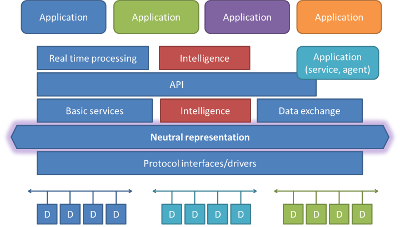
- The “tooooo smart” gateway (shown in Figure 3b). This approach relies on an additional (or more powerful) component, still at the device level (D), which incorporates the required complexity and is the preferred solution for hardware component manufacturers. These devices are usually called “smart gateways,” “web servers,” “controllers” or similar: they take the role of intermediating with the underlying devices and offer high-level function to the applications. For example, these smart gateways may allow data collection, automatic sending of data via FTP (File Transfer Protocol) or e-mail, may embed a small web interface, may autonomously apply some simple logic (such as the one used by PLC—Programmable Logic Controller—devices) for sending commands, etc. Applications are simpler, since they can rely on the higher level functions offered by the gateway. Again, there are several disadvantages with this approach: first, it is limited to the set of devices that the gateway is able to handle, as new devices or other protocols are not supported at this level. Second, the offered functionality is not extensible (unless we hope for the device manufacturer to provide a new version with the needed extensions), as it is bound to the gateway implementation, and this can require some workarounds at the application level. Finally, the applications will be bound to the application programming interface (API) offered by the gateway: while the field-level communications among devices are standardized, these APIs are highly specific to each device and each manufacturer, and the development of the application will heavily rely on the specific API, thus creating a long-term commitment to reuse the application only in conjunction with the same gateway.
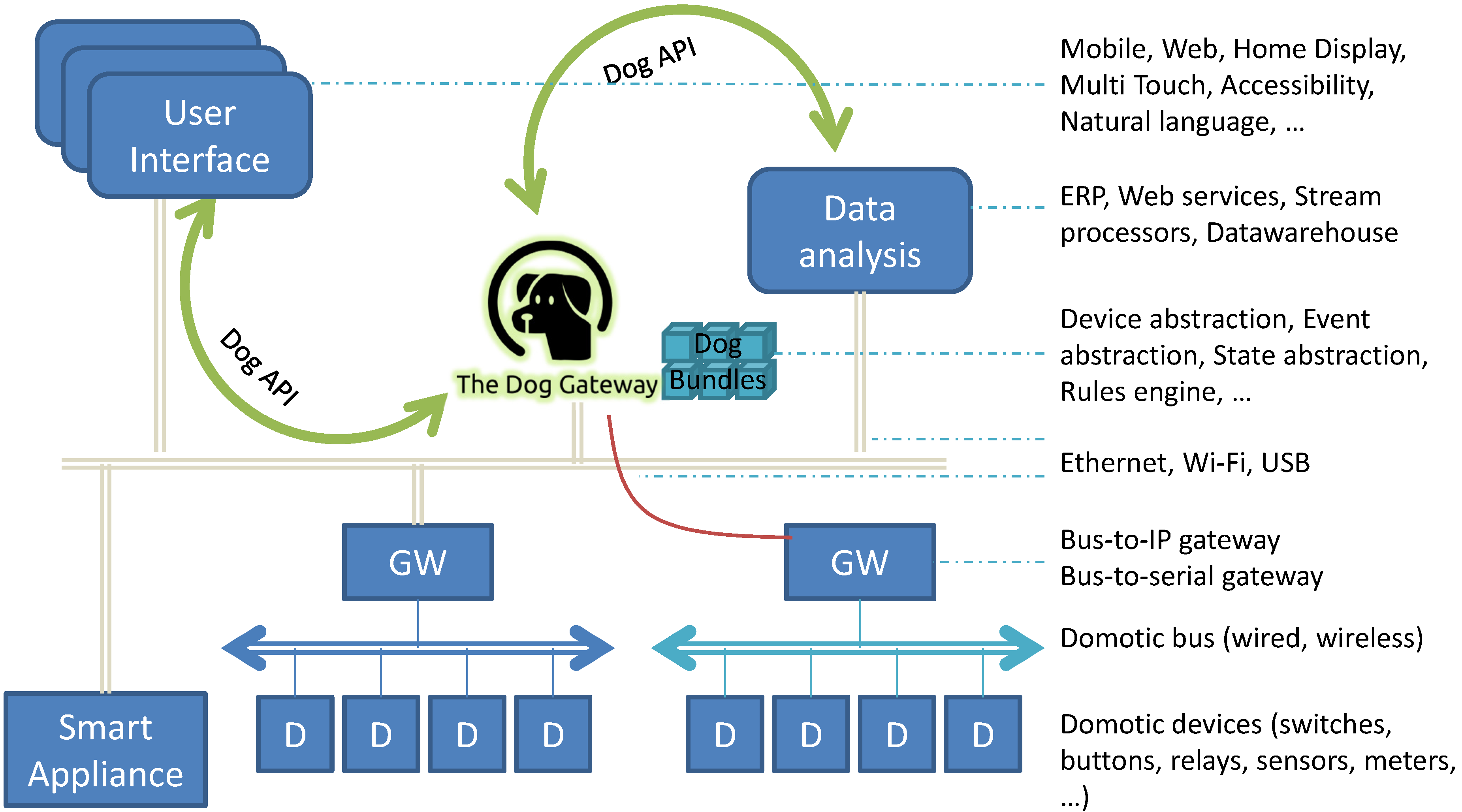
2.3. Semantics-Rich Architectures

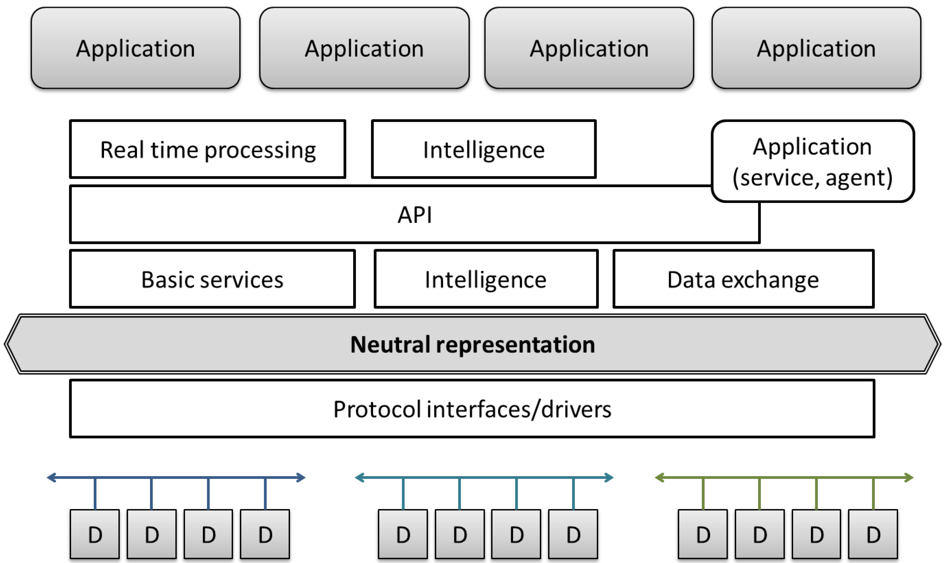
- Protocol interfaces/drivers. This is the only layer lying below the ontology representation. This level is the only one with actual knowledge of the hardware protocols and components available in the building and is able to translate between high level commands (such as kitchenLamp.On()) into low-level protocol-dependent messages (such as , an actual command for switching on Lamp Number 12 in the Open WebNet protocol). This layer may be composed of many drivers, one for each supported technology, thus offering the possibility of managing systems composed of various protocols (as suggested by the different groups of devices in the picture) in a seamless way.
- Basic services. On top of the neutral representation, some basic management services are needed, such as the ability to query the list of represented devices, their capabilities, their current (or last-seen) state and the discovery and configuration of new devices. Such services basically compose an object-oriented high-level wrapper around the semantically modeled devices, and hide most of the complexity of the ontology modeling.
- API. The services (basic and advanced) offered by the middleware should be easily accessible by applications, through a well-defined and possible stable application programming interface. Such an API defines all of the application-visible functionalities offered by the middleware, which in turn represent and extend the functionalities offered by the devices in the building. The same set of functions may be offered in different programming languages, by implementing proper API bindings (e.g., a Java binding, a C# binding, an HTTP (Hypertext Transfer Protocol) binding, a WebSockets binding, etc.), so that applications may be developed in different programming languages and may also be distributed in different computational nodes, but still have the same control capabilities.
- Real-time processing. In case some real-time processing is needed, this optional layer may provide stream processing capabilities (such as the ones described in [3]) to compute on-the-fly quantities, such as averages, counts, sums, thresholds and integrals, and, therefore, enable locally-generated messages (such as alerts) or reduce the amount of traffic sent to external applications (by transmitting aggregate data, only).
- Data exchange. This layer may optionally be adopted for storing, importing, exporting or querying data coming from the building sensors and actuators. Depending on the requirements, this could imply storing locally a history of recently read values and/or sending to a remote server such data for further application-level processing.
- Intelligence. The availability of semantically-rich information about the building, its devices, their functionality and their current state may enable the implementation of “intelligent” behaviors (either by directly working on the ontology, which supports reasoning operations in OWL) or by using the defined APIs.
3. Related Works
3.1. Middleware
3.1.1. Programming Frameworks
3.2. Semantic-Based Applications
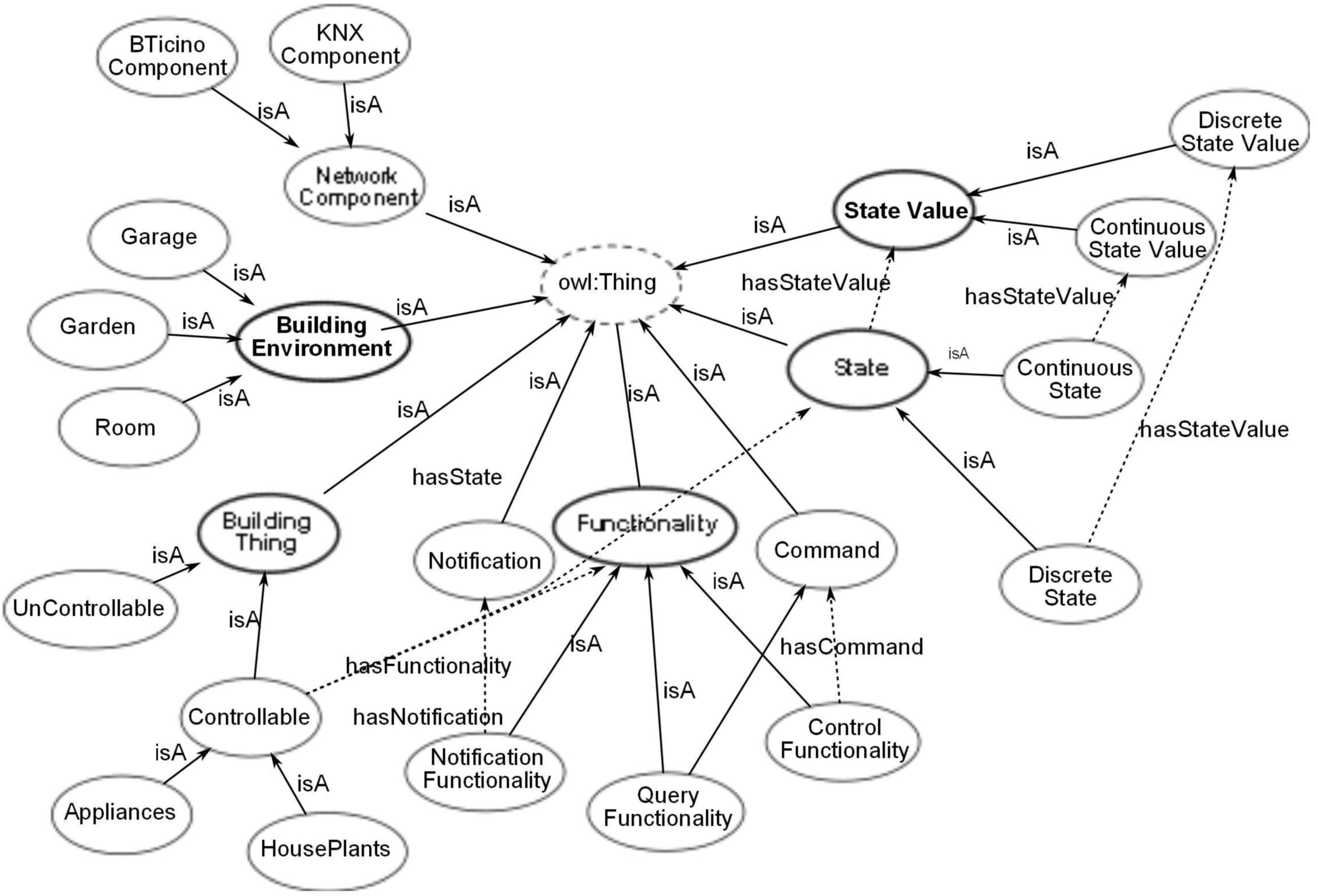
4. The DogOnt ontology
- The domotic environment structure (rooms, walls, doors, etc.), by means of concepts descending from BuildingEnvironment; they might be automatically generated starting from BIM (Building Information Modeling) data, if available, which is mainly useful for locating devices inside the building, by specifying the room or wall in which they are installed.
- The type of domotic devices and of smart appliances (concepts descending from the Controllable subclass of the BuildingThing main concept); this branch is the main one and is better described in the following.
- The working configurations that devices can assume, modeled by tates and StateValues; used to describe devices of the Controllable type; see the following paragraphs for more details).
- The device capabilities Functionalities) in terms of accepted events and generated messages, i.e., Commands and Notifications; again, they are used to describe the behavior of Controllables.
- The technology-specific information needed for interfacing real-world devices NetworkComponent); the only branch where the encoded information depends on the details of the installed devices and should never be accessed by the upper layers of the architecture.
- The kind of furniture placed in the home (concepts descending from the UnControllable subclass of the BuildingThing main concept); this is a purely optional branch and might be useful for some kinds of spatial reasoning, which are outside the scope of the middleware.
- ControlFunctionalities, modeling the ability of a device to be controlled by means of some message or command;
- QueryFunctionalities, modeling the ability of a device to be queried about its current state; and
- NotificationFunctionalities, modeling the ability of a device to issue notifications about state changes, in an event-driven interaction model.
5. The Dog Gateway

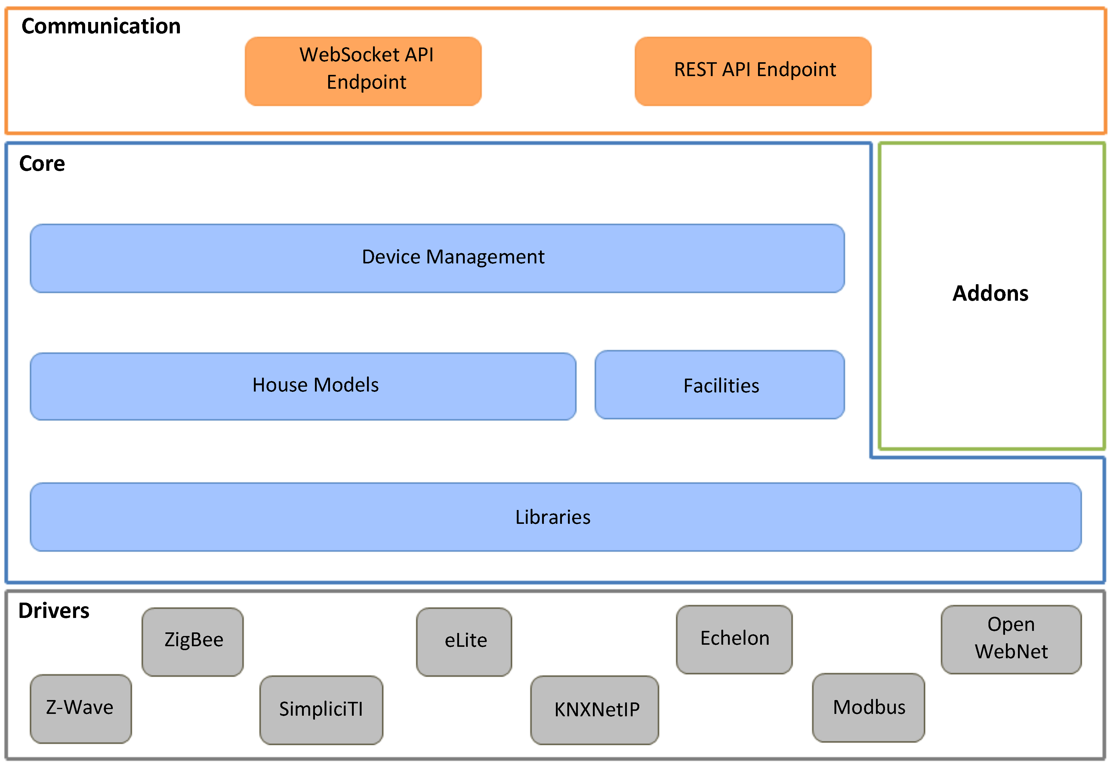
5.1. Architecture

5.1.1. Drivers’ Layer
5.1.2. Core Layer
- It contains all of the possible devices, functionalities, states and state values as defined in DogOnt; all of these classes and interfaces are programmatically generated from DogOnt, thus ensuring a formal and full compliance with the ontology representations.
- It encompasses all of the possible device implementations, defined as abstract classes and programmatically generated from the previous part.
- It provides core-level notifications, i.e., not defined in DogOnt, as well as common data structures needed by the other Dog bundles.
- It provides utility classes to other bundles, to avoid code duplications and repetitions.
5.1.3. Addons Layer
5.1.4. Communication Layer
5.2. Implementation
6. Case Study
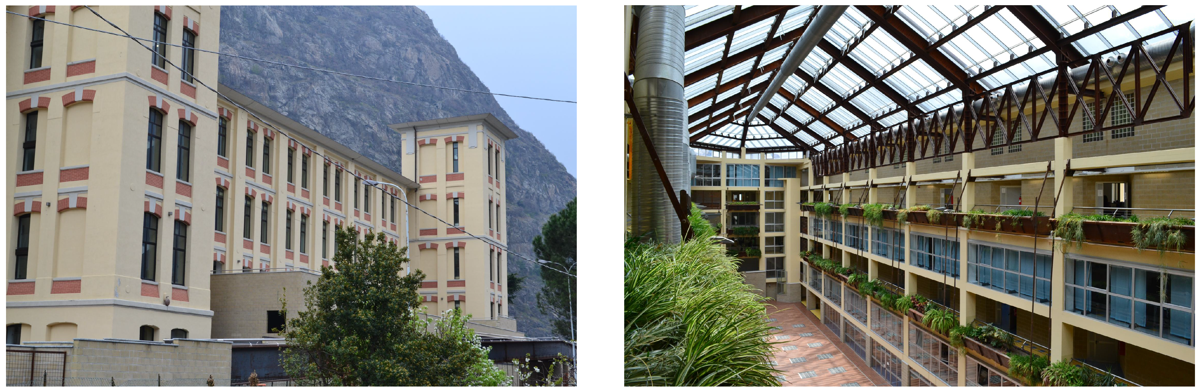
- One building in the town of Verrès (in the Aosta region), Italy, which hosts a secondary technical school and a university college degree program. The building, shown in Figure 8, was renovated around 10 years ago, starting from an old abandoned cotton factory; it features a large central gallery (closed with glass windows on the top) and seven stories of balconies, which host classrooms, laboratories and offices. The building has a state-of-the-art climate control system, featuring air control units for both classrooms and for the central gallery; the electrical system is well built, but featured no automation nor control.
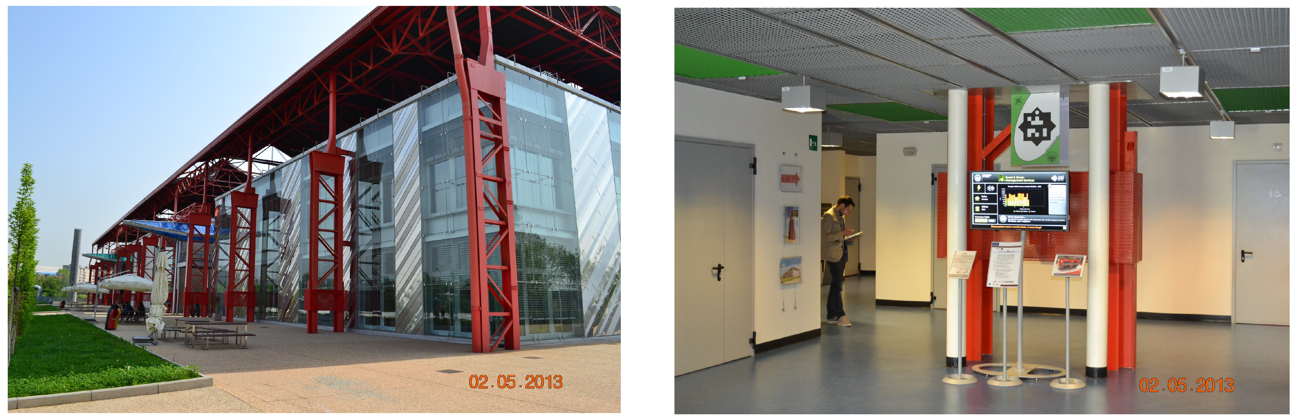
- One building in the city of Torino, Italy, in the area called Mirafiori, which hosts a part of the campus of the Politecnico di Torino university. The building, shown in Figure 9, was totally renovated in 2011 staring from a group of production buildings formerly owned by FIAT Auto. The building contains classrooms, laboratories and some offices and features a climate control system and an electrical control and monitoring system, both quite modern, but completely separated (a nice example of side-by-side vertical architectures).

- In Verrès, there was no electrical monitoring system. This is sort of an easy case, since we had then the possibility of choosing the most suitable technology. It was not easy to pull serial lines across the electric plant, but there were free Ethernet lines running nearby: we decided to install new electricity meters and send their data over the local Ethernet LAN. We chose ModBus meters encapsulated in RTU over IP.
- In Verrès, the air and temperature control system was built using a proprietary system, with no documentation available for connecting. However, the system was already measuring a lot of temperatures and humidity values across the whole building (to feed its control algorithm), so we decided to try and re-use such information without adding new environmental sensors. With the collaboration of the company managing the plant, we asked them to install a converter from their protocol into ModBus, so that a subset of the sensor values could be read over ModBus/TCP.
- In Verrès, the huge central gallery did not have sufficient environmental sensors (the variables provided by the control system were too sparse), so we decided to add new sensors. Due to the size and the construction of the gallery, it would have been difficult to install new wired sensors, so we opted for wireless sensors adopting the ZigBee protocol.
- In Mirafiori, the electricity distribution was already metered, thanks to a ModBus system, and it already had TCP gateways: it was therefore easy to get the needed information using the ModBus/TCP protocol, with the collaboration of the system builders.
- In Mirafiori, also, the thermal control was automated, although using a completely different wiring and gateway. Due to difficulties of communication with the system builders, we resorted to extract (in a periodic and automatic way) the necessary information from the management software that was running on a control PC.
- In Mirafiori, we wanted to have some more detailed information about the behavior of the students in a study room (where they can plug in their PCs, control lights and blinds), so we added additional sensors (light, temperature, humidity and electrical consumption on a desk-by-desk basis). Again, we adopted a mixture of ZigBee and ModBus protocols.

6.1. Lessons Learned
- Adding new “Driver” modules to compensate for new protocols encountered by pre-existing BMS systems (and this work would capitalize on future implementations).
- Modeling the set of devices and the building configurations, by creating suitable sets of semantic instances.
- Defining the streaming computation chains to compute significant indicators starting from raw measurements.
7. Conclusions
Acknowledgments
Author Contributions
Conflicts of Interest
References
- Capehart, B.L.; Middelkoop, T. Handbook of Web Based Energy Information and Control Systems, 1st ed.; Fairmont Press: Lilburn, GA, USA, 2011. [Google Scholar]
- Bonino, D.; Corno, F. DogOnt—Ontology Modeling for Intelligent Domotic Environments. In Proceedings of the Semantic Web—ISWC 2008, Karlsruhe, Germany, 26–30 October 2008; Sheth, A., Staab, S., Dean, M., Paolucci, M., Maynard, D., Finin, T., Thirunarayan, K., Eds.; Springer-Verlag: New York, NY, USA, 2008; pp. 790–803. [Google Scholar]
- Bonino, D.; Corno, F.; de Russis, L. Real-Time Big Data Processing for Domain Experts, An Application to Smart Buildings. In Big Data Computing/Rajendra Akerkar; Taylor & Francis Press: London, UK, 2013; Volume 1, pp. 415–447, ref.2. [Google Scholar]
- De Russis, L. Interacting with Smart Environments: Users, Interfaces, and Devices. Ph.D. Thesis, Politecnico di Torino, Torino, Italy, 2014. [Google Scholar]
- Cook, D.J.; Augusto, J.C.; Jakkula, V.R. Ambient intelligence: Technologies, applications, and opportunities. Pervas. Mob. Comput. 2009, 5, 277–298. [Google Scholar] [CrossRef]
- Sadri, F. Ambient intelligence: A survey. ACM Comput. Surv. 2011, 43, 1–66. [Google Scholar] [CrossRef]
- Bonino, D.; de Russis, L.; Corno, F.; Ferrero, G. JEERP: Energy aware enterprise resource planning. IT Prof. 2014, 16, 50–56. [Google Scholar] [CrossRef]
- Boyer, S. SCADA: Supervisory Control and Data Acquisition; International Society of Automation: Durham, NC, USA, 2010. [Google Scholar]
- Neill, C.J.; Laplante, P.A. Antipatterns: Identification, Refactoring, and Management; CRC Press: Boca Raton, FL, USA, 2005. [Google Scholar]
- Koenig, A. Patterns and Antipatterns. In The Patterns Handbook: Techniques, Strategies, and Applications; Cambridge University Press: Cambridge, UK, 1998; pp. 383–390. [Google Scholar]
- Völter, M.; Stahl, T.; Bettin, J.; Haase, A.; Helsen, S. Model-Driven Software Development: Technology, Engineering, Management; John Wiley & Sons: Hoboken, NJ, USA, 2013. [Google Scholar]
- Bonino, D.; Corno, F. DoMAIns: Domain-based modeling for ambient intelligence. Pervas. Mob. Comput. 2012, 8, 614–628. [Google Scholar] [CrossRef]
- Berners-Lee, T.; Hendler, J.; Lassila, O. The semantic web. Sci. Am. 2001, 284, 34–43. [Google Scholar] [CrossRef]
- Mcguinness, D.L.; van Harmelen, F. OWL Web Ontology Language Overview; W3C: Cambridge, MA, USA, 2004. [Google Scholar]
- Bonino, D.; Castellina, E.; Corno, F. The DOG gateway: Enabling ontology-based intelligent domotic environments. IEEE Trans. Consum. Electron. 2008, 54, 1656–1664. [Google Scholar] [CrossRef]
- Bonino, D.; Procaccianti, G. Exploiting semantic technologies in smart environments and grids: Emerging roles and case studies. Sci. Comput. Programm. 2014, 95, 112–134. [Google Scholar] [CrossRef]
- Vernadat, F. Enterprise Modelling and Integration. In Enterprise Inter- and Intra-Organizational Integration; Kosanke, K., Jochem, R., Nell, J., Bas, A., Eds.; Springer: New York, NY, USA, 2003; Volume 108, pp. 25–33. [Google Scholar]
- Niu, N.; Xu, L.D.; Bi, Z. Enterprise information systems architecture-analysis and evaluation. IEEE Trans. Ind. Inform. 2013, 9, 2147–2154. [Google Scholar] [CrossRef]
- Smart Appliances Study SMART 2013/0007. Available online: https://sites.google.com/site/smartappliancesproject/ (accessed on 31 October 2014).
- Den Hartog, F.; Daniele, L.; Roes, J. Study on Semantic Assets for Smart Appliances Interoperability—D-S1: FIRST INTERIM REPORT; Technical Report for TNO Innovation for Life: Brussels, Belgium, 2014. [Google Scholar]
- Nakashima, H.; Aghajan, H.; Augusto, J.C. Handbook of Ambient Intelligence and Smart Environments, 1st ed.; Springer: New York, NY, USA, 2009. [Google Scholar]
- Varela, G.; Paz-Lopez, A.; Becerra, J.A.; Vazquez-Rodriguez, S.; Duro, R.J. UniDA: Uniform device access framework for human interaction environments. Sensors 2011, 11, 9361–9392. [Google Scholar] [CrossRef] [PubMed]
- Ni, H.; Abdulrazak, B.; Zhang, D.; Wu, S. CDTOM: A context-driven task-oriented middleware for pervasive homecare environment. Int. J. UbiComp 2011, 2, 34–53. [Google Scholar] [CrossRef]
- Cook, D.; Crandall, A.; Thomas, B.; Krishnan, N. CASAS: A smart home in a box. Computer 2013, 46, 62–69. [Google Scholar] [CrossRef] [PubMed]
- Cook, D.; Schmitter-Edgecombe, M.; Crandall, A.; Sanders, C.; Thomas, B. Collecting and Disseminating Smart Home Sensor Data in the CASAS Project. In Proceedings of the CHI09 Workshop on Developing Shared Home Behavior Datasets to Advance HCI and Ubiquitous Computing Research, Boston, MA, USA, 4–9 April 2009.
- Henricksen, K.; Indulska, J.; McFadden, T.; Balasubramaniam, S. Middleware for Distributed Context-Aware Systems. In On the Move to Meaningful Internet Systems 2005: CoopIS, DOA, and ODBASE; Springer: New York, NY, USA, 2005; pp. 846–863. [Google Scholar]
- Eisenhauer, M.; Rosengren, P.; Antolin, P. A Development Platform for Integrating Wireless Devices and Sensors into Ambient Intelligence Systems. In Proceedings of the 6th Annual IEEE Communications Society Conference on SECON Workshops’ 09, Rome, Italy, 22–26 June 2009; pp. 1–3.
- Eisenhauer, M.; Rosengren, P.; Antolin, P. Hydra: A Development Platform for Integrating Wireless Devices and Sensors into Ambient Intelligence Systems. In The Internet of Things; Springer: New York, NY, USA, 2010; pp. 367–373. [Google Scholar]
- Madhusudanan, J.; Hariharan, S.; Selvan, M.A.; Venkatesan, V.P. A generic middleware model for smart home. Int. J. Comput. Netw. Inform. Secur. 2014, 6, 19–25. [Google Scholar]
- Atzori, L.; Iera, A.; Morabito, G. The Internet of things: A survey. Comput. Netw. 2010, 54, 2787–2805. [Google Scholar] [CrossRef]
- Bandyopadhyay, S.; Sengupta, M.; Maiti, S.; Dutta, S. A Survey of Middleware for Internet of Things. In Recent Trends in Wireless and Mobile Networks; Özcan, A., Zizka, J., Nagamalai, D., Eds.; Springer: Berlin-Heidelberg, Germany, 2011; Volume 162, pp. 288–296. [Google Scholar]
- Souza, A.M.; Amazonas, J.R. A Novel Smart Home Application Using an Internet of Things Middleware. In Proceedings of the 2013 European Conference on Smart Objects, Systems and Technologies (SmartSysTech), Erlangen, Germany, 11–12 June 2013; pp. 1–7.
- Perumal, T.; Ramli, A.; Leong, C.Y. Interoperability framework for smart home systems. IEEE Trans. Consum. Electron. 2011, 57, 1607–1611. [Google Scholar] [CrossRef]
- Reinisch, C.; Kofler, M.; Kastner, W. ThinkHome: A Smart Home as Digital Ecosystem. In Proceedings of the 2010 4th IEEE International Conference on Digital Ecosystems and Technologies (DEST), Dubai, United Arab Emirates, 13–16 April 2010; pp. 256–261.
- Reinisch, C.; Kofler, M.J.; Iglesias, F.; Kastner, W. ThinkHome energy efficiency in future smart homes. EURASIP J. Embed. Syst. 2011, 2011, 1–18. [Google Scholar] [CrossRef]
- The Saving Energy in Europe’s Public Buildings Using ICT (SMARTSPACES) Project. Available online: http://www.smartspaces.eu/ (accessed on 31 October 2014).
- The OSGi Alliance. OSGi Release 5. Available online: http://www.osgi.org/Specifications (accessed on 31 October 2014).
- Fensel, A.; Tomic, S.; Kumar, V.; Stefanovic, M.; Aleshin, S.V.; Novikov, D.O. SESAME-S: Semantic smart home system for energy efficiency. Inform. Spektrum 2013, 36, 46–57. [Google Scholar] [CrossRef]
- Fensel, A.V.; Kumar, V.; Tomic, S. End user interfaces for energy efficient semantically-snabled smart homes. Energy Effic. 2014, 7, 655–675. [Google Scholar] [CrossRef]
- Kumar, V.; Fensel, A.; Fröhlich, P. Context Based Adaptation of Semantic Rules in Smart Buildings. In Proceedings of the International Conference on Information Integration and Web-Based Applications & Services, Bali, Indonesia, 3–5 December 2012.
- Kumar, V.; Fensel, A.; Lazendic, G.; Lehner, U. Semantic Policy-Based Data Management for Energy Efficient Smart Buildings. In On the Move to Meaningful Internet Systems: OTM 2012 Workshops, Rome, Italy, 10–14 September 2012; Herrero, P., Panetto, H., Meersman, R., Dillon, T., Eds.; Springer: Berlin-Heidelberg, Germany, 2012; Volume 7567, pp. 272–281. [Google Scholar]
- Sang, J.; Ye, C.; Hu, H.; Li, R.; Fu, L.; Yang, D.; Xiang, H.; Fu, C. Semantic web-based policy interaction detection method with rules in smart home for detecting interactions among user policies. IET Commun. 2011, 5, 2451–2460. [Google Scholar] [CrossRef]
- Girtelschmid, S.; Steinbauer, M.; Kumar, V.; Fensel, A.; Kotsis, G. On the application of Big Data in future large scale intelligent Smart City installations. Int. J. Pervas. Comput. Commun. 2014, 10, 168–182. [Google Scholar] [CrossRef]
- Gruber, T. Toward principles for the design of ontologies used for knowledge sharing. Int. J. Hum. Comput. Stud. 1995, 43, 907–928. [Google Scholar] [CrossRef]
- DogOnt Ontology Documentation. Available online: http://elite.polito.it/ontologies/dogont/dogont.html (accessed on 31 October 2014).
- DogOnt Ontology OWL download. Available online: http://elite.polito.it/ontologies/dogont.owl (accessed on 31 October 2014).
- Furfari, F.; Sommaruga, L.; Soria, C.; Fresco, R. DomoML: The Definition of a Standard Markup for Interoperability of Human Home Interactions. In Proceedings of the 2nd European Union Symposium on Ambient Intelligence, Eindhoven, The Netherlands, 8–10 November 2004; pp. 41–44.
- The Dog Gateway Project. Available online: http://dog-gateway.github.io (accessed on 31 October 2014).
- Bonino, D.; Corno, F. SpChains: A declarative framework for data stream processing in pervasive applications. Procedia Comput. Sci. 2012, 10, 316–323. [Google Scholar] [CrossRef]
© 2014 by the authors; licensee MDPI, Basel, Switzerland. This article is an open access article distributed under the terms and conditions of the Creative Commons Attribution license (http://creativecommons.org/licenses/by/4.0/).
Share and Cite
Bonino, D.; Corno, F.; De Russis, L. A Semantics-Rich Information Technology Architecture for Smart Buildings. Buildings 2014, 4, 880-910. https://doi.org/10.3390/buildings4040880
Bonino D, Corno F, De Russis L. A Semantics-Rich Information Technology Architecture for Smart Buildings. Buildings. 2014; 4(4):880-910. https://doi.org/10.3390/buildings4040880
Chicago/Turabian StyleBonino, Dario, Fulvio Corno, and Luigi De Russis. 2014. "A Semantics-Rich Information Technology Architecture for Smart Buildings" Buildings 4, no. 4: 880-910. https://doi.org/10.3390/buildings4040880